Digital I/O, Ignition, and CAN Bus Connectivity

This chapter contains the following sections:

Overview of the Digital I/O, Ignition, and CAN Bus Connectivity

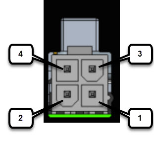
The connector has four GPIO connections, one Return connection, and one Ignition connection. The Digital I/O supports both Dry and Wet contacts up to 60 V.

  • Dry contact is isolated from a voltage source (or no volt), with an embedded relay function (NPN transistor), usually used to indicate an event, for example, open/close, alarm.

  • Wet contact is a contact with external power (+3.3V to +60V, and a maximum 150mA of current allowed at high voltage) applied, and is usually used to energize something, for example, solenoid, light.

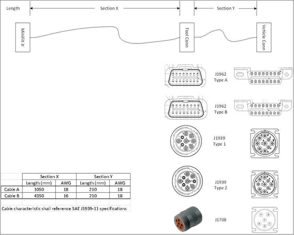
  • Connectivity for the CAN Bus is through two wires on the power connector that connects to the OBD-II connector of the vehicle.

Digital I/O Features

The common features of Digital I/O are:

  • Withstands up to 60V applied at the terminal.
  • Protected from reverse voltage and causes no damage to the equipment.
  • Digital input and output can coexist on different channels.
  • LED Indicator: Provisionable; On: Active, Off: Non-active.
  • 4kV surge protected (IEC 61000-4-5).

The Digital I/O Connector

The following figure shows the connector.

Figure 1. Digital I/O Connector

Note


The default state of the Digital I/O is input, the open-collector is open (off).

The power connector pinouts are as follows:

  • Top Row: Pins 6, 5, 4
  • Bottom Row: Pins 3, 2, 1

The pinouts for the Digital I/O are described in the following table.

Table 1. Digital I/O Pinouts

Pin #

Name

Direction

Description

1

DIGI_IO_1

I/O

Digital IO Port 3

2

GND

Ground

3

DIGI_IO_3

I/O

Digital IO Port 2

4

DIGI_IO_2

I/O

Digital IO Port 4

5

Ignition

In

Ignition input (6V - 36V)

6

DIGI_IO_4

I/O

Digital IO Port 1

Vehicle Connections

When connecting to automotive power, it is expected that the ignition output will be +12 VDC, or +24 VDC (following the battery voltage). Connect the ignition input of the router to the ignition output of the automobile. The DC In + and DC In - leads can be directly connected to the battery. However, we recommend that you connect them after a fuse.


Important


For vehicle installations, it is required to connect the ignition input, and use the Ignition Power Management feature of the router. This eliminates unnecessary power cycling of the router whenever the vehicle is turned off and then turned back on.

Digital I/O Specifications

Digital I/O specifications are described in the following tables.

Table 2. Digital Input Specifications

Specification

Minimum

Maximum

Unit

Input Voltage High

2.2

60

Volts

Input Voltage Low

1.2

Volts

Input Current

0.68mA

mA


Note


Current is flowing out of the terminal although it is an input, that is, sourcing. The current is flowing in the terminal for the output, that is, sinking.
Table 3. Digital Output Specifications

Specification

Minimum

Maximum

Unit

Notes

Output Voltage High

2.5

Volts

No external voltage applied.

Output Voltage Low

0.4

Volts

No external voltage applied.

Internal Pull-Up Resistance

1K – 1%

1K – 1%

Ohms

Internal Pull-Up Voltage

3

Volts

External Pull-Up Voltage

3.3

60

Volts

External resistance required to limit current to 200mA.

Sink Current

200

mA

Controller Area Network Bus Features

The IR1800 features support for the Controller Area Network (CAN) Bus interface through two wires that connect to the OBD-II connector of the vehicle.

The following are some of the characteristics of the CAN Bus:

  • CAN Bus enables the ECU (electronic control unit) in a vehicle to communicate with all other ECUs

  • Consists of two wires: CAN Bus High and Low, supporting data rate up to 1 Mbs

  • High-speed CAN Bus 2.0B: ISO 11898-1 data link layer, ISO 11898-2 and ISO-11898-5 physical layer up to 1 Mbs data rate (software dependent)

  • Maximum cable length between 500 m (125 kbit/s) and 40 m (1 Mbit/s)

  • 120-ohms CAN Bus termination

  • There is no hardware mechanism to detect if an ODB II connector is attached

Can Bus Power Connector

The CAN_P and CAN_N signals are connected to two pins of the 4-pin mini-fit power connector. A cable can be connected from the mini-fit connector to the OBD-II connector of the vehicle to get both unswitched power and CAN interface input.

The pinouts are shown in the following figure.

Figure 2. Power Connector
Table 4. Power Connector Descriptions

Pin Number

Name

Description

1

DC -

DC Power Return (GND-)

2

CAN_P

CAN Bus Differential Signal

3

DC +

DC Power Input (12V, 24V)

4

CAN_N

CAN Bus Differential Signal

On-Board Diagnostic (OBD-II)

The following are some of the characteristics of On-Board Diagnostic (OBD-II):

  • OBD or OBDI standardizes the connector so that it is identical in all the vehicles

  • The communication protocol remains somewhat specific depending on the make of the vehicle

  • The OBDII port is always powered up, even when the vehicle is turned off

  • When connecting an IR1800 CAN Bus, the vehicles owner must review the characteristics of the ODB2 power and fuse protection

The following are the different types of OBD-II cables depending on the model of vehicle you are installing the router in.

Table 5. OBD-II Cable Descriptions

OBD2-J1962YA-MF4

OBD-II (J1962) Type A to Router cable with type 1 Y

OBD2-J1962YB-MF4

OBD-II (J1962) Type B to Router cable with type 2 Y

OBD2-J1939Y2-MF4

OBD-II (J1939) Type 2 heavy duty diagnostic harness for Volvo

OBD2-J1939Y1-MF4

OBD-II (J1939) Type 1 to Router cable with type 1 Y

OBD2-J1708Y-MF4

OBD-II (J1708) to Router cable with type 1 y-split

OBD2-J1962VMB-MF4

J1962-VM-Type B Volvo & Mack

The list of cables is illustrated in the following figure. The box labeled Vehicle Conn is the connector that is connected to a car or truck. The box labeled Tool Conn is for attaching diagnostic tool. The box labeled MiniFit-Jr is the connector that connects to the IR1800.