Pluggable Interface Modules

This chapter contains the following sections

Introduction to Installing Pluggable Interface Modules

This section describes the equipment and the procedures for successfully installing the Cisco Pluggable Interface Modules (PIM).


Important


The Pluggable Module is not hot swappable. The router must be reloaded after a new module is installed.

The highlights of the LTE PIM are:

  • All cellular interfaces are supported through a PIM

  • We recommend that you use Industrial Temp micro SIMs, 3FF size, that are rated from -40C to +105C

  • To ensure a reliable contact to the SIM socket, gold-plated SIM cards must be used.

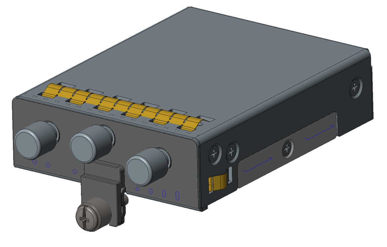
The following images show examples of a pluggable module. In this case, the LTE pluggable module.

Figure 1. LTE Pluggable Module (Front)

Item

Description

1

Cellular-Main SMA

2

GPS SMA

3

Cellular-Div SMA

4

Enable LED

5

SIM 0 LED

6

SIM 1 LED

7

GPS LED

8

RSSI LEDs

Installing a PIM

The modular cellular modem pluggable module's Remove and Replace options follow.

The IR1800 may have a blank plate covering the pluggable module slot. If it exists, remove it prior to installing the cellular modem module. The following steps show the LTE pluggable module, however, they apply to other modules as well.

Procedure


Step 1

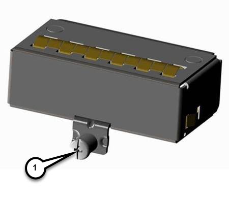
Remove the blank plate by unscrewing the latch lock screw(1 ) that holds the plate secure. Refer to the following graphic.

Figure 2. Latch Lock Screw

1

Latch lock screw

Step 2

Slide the blank plate out of the device.

Step 3

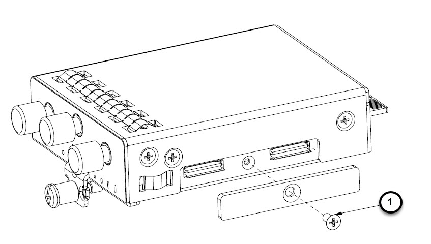
Prepare the cellular modem module by inserting the micro sims that are applicable for your modems into the device. Remove the screw (1 ) holding the access plate which covers the SIM slots. The access plate is located on the side of the module, as shown in the following figures.

Figure 3. SIM Access Plate

1

Access plate screw

Step 4

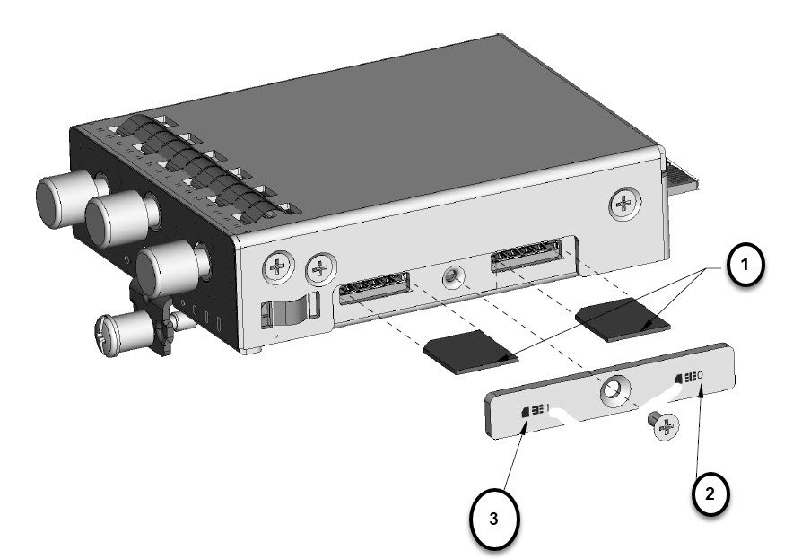
Install your SIMs as shown in the following figure. Make note of the slot number and SIM orientation.

Figure 4. SIM Installation

1

Micro SIMs

2

SIM 0

3

SIM 1

Step 5

Push each SIM until it clicks into place. After the SIMs are installed, reattach the access plate that you previously removedearlier using a screwdriver. Torque to 2.8 to 3.8 inch-lbs (0.9-1.1 Newton meter).

Note

 
Ensure that the cover is properly aligned with the screw hole.

Step 6

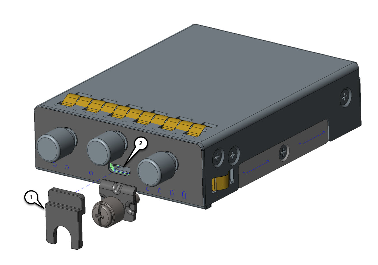
If your pluggable module is the type that has a USB port, make sure that the USB cover is properly installed. Place the USB cover (1 ) with the plug indentation against the USB port (2 ), as shown in the following figure. The half circle of the USB cover fits behind the latch lock screw.

Figure 5. USB Port Cover Installation

1

USB cover

2

USB port

Step 7

Tighten the latch lock screw to a torque of 2.8 to 3.8 inch-lbs (0.3 to 0.4 Newton meter). The following figure shows a finished USB cover installation.

Figure 6. Completed USB Cover Installation

Step 8

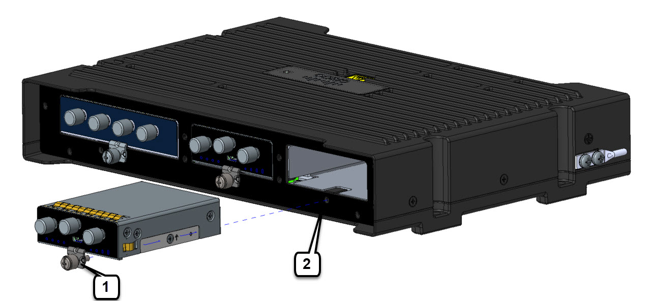
Slide the pluggable module into the device, as shown in the following figure. The latch lock screw (1 ) aligns with the screw hole (2 ) on the face of the device. Push the pluggable module all the way into the device until you feel it seat, and then torque the latch lock screw 8-10 inch-pound (0.9 to 1.1 Newton meter).

Figure 7. Pluggable Module Insertion

1

Latch lock screw

2

Screw hole

Step 9

Attach your antenna cables to the ports on the pluggable module. There are different instructions for each antenna type. So be sure to consult the corresponding antenna documentation for proper orientation and torque to install them.

Note

 
If no antenna cables are being installed on a port, make sure the caps are installed on the unused connector.