M12 Kit Overview
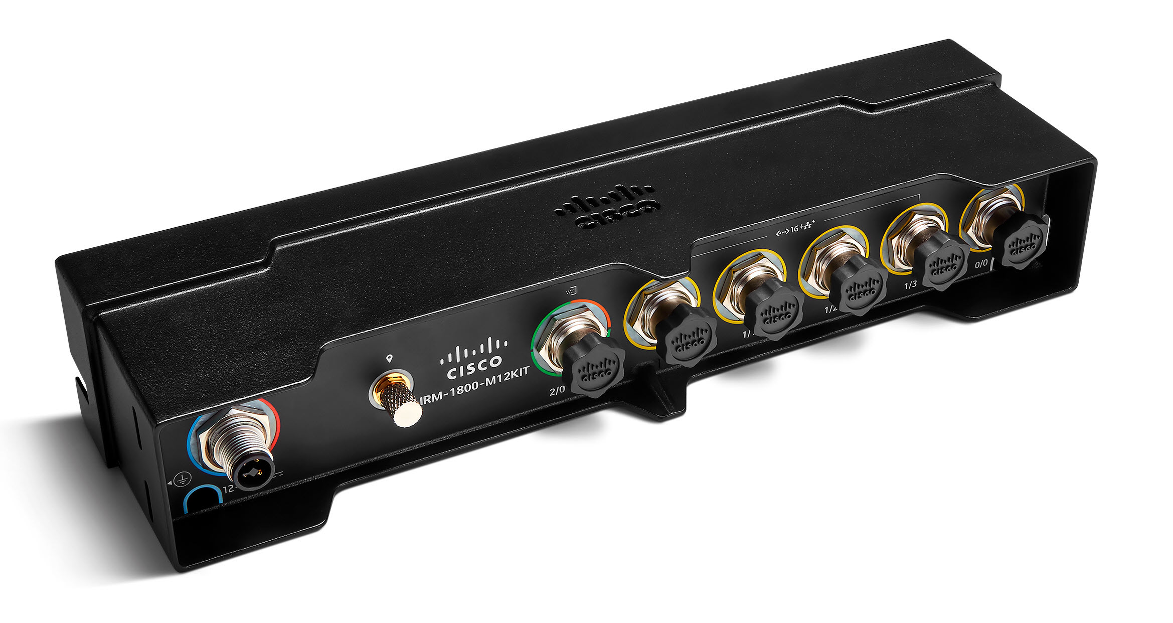
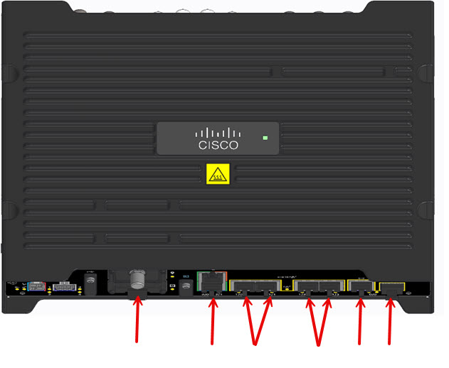
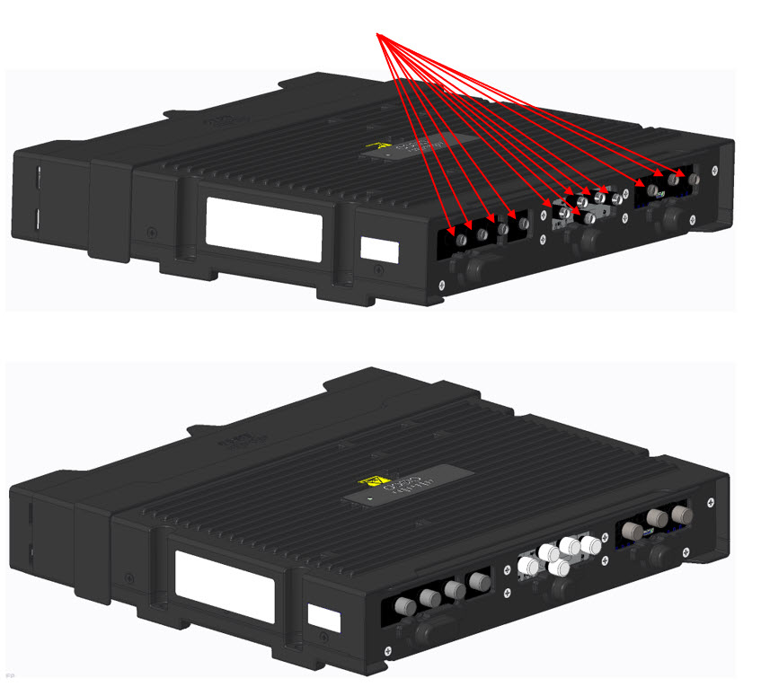
The M12 kit for the Catalyst IR1800 routers is a plug-on module that converts its various interface ports into M12 ports. The part number for the kit is IRM-1800-M12KIT.
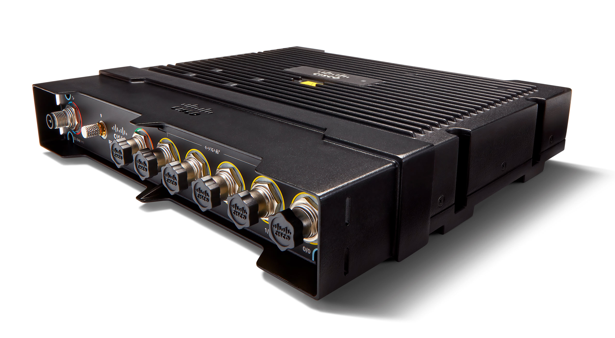
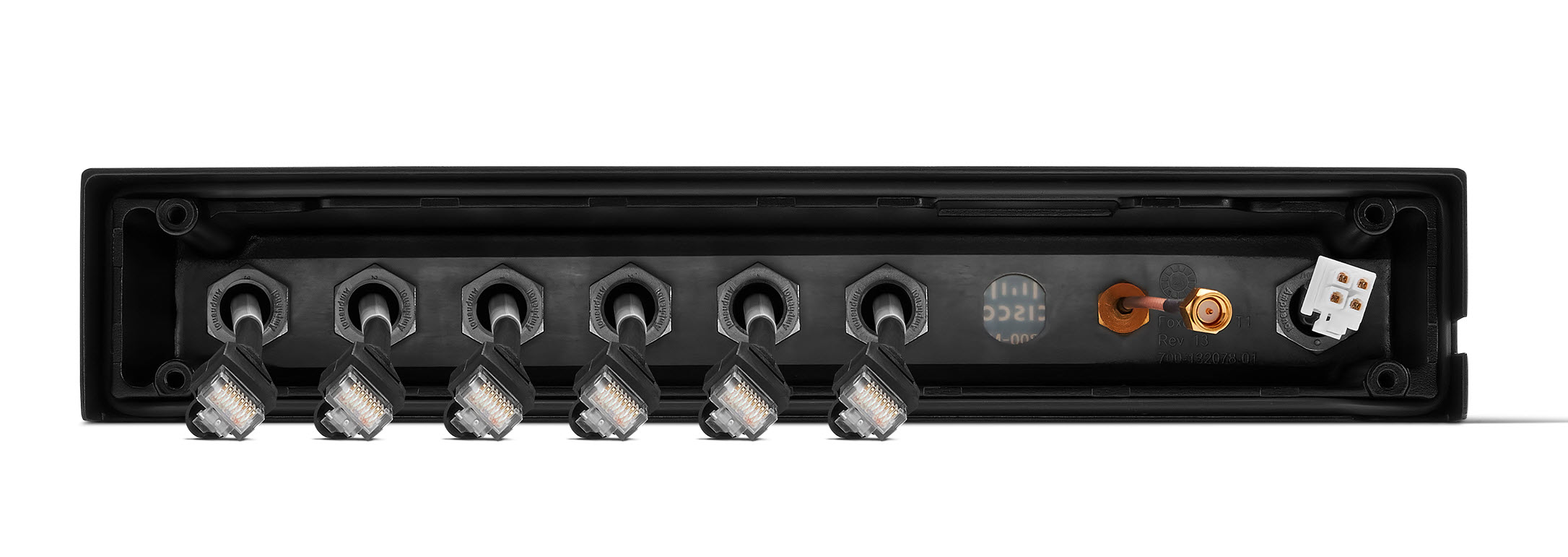
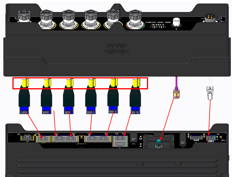
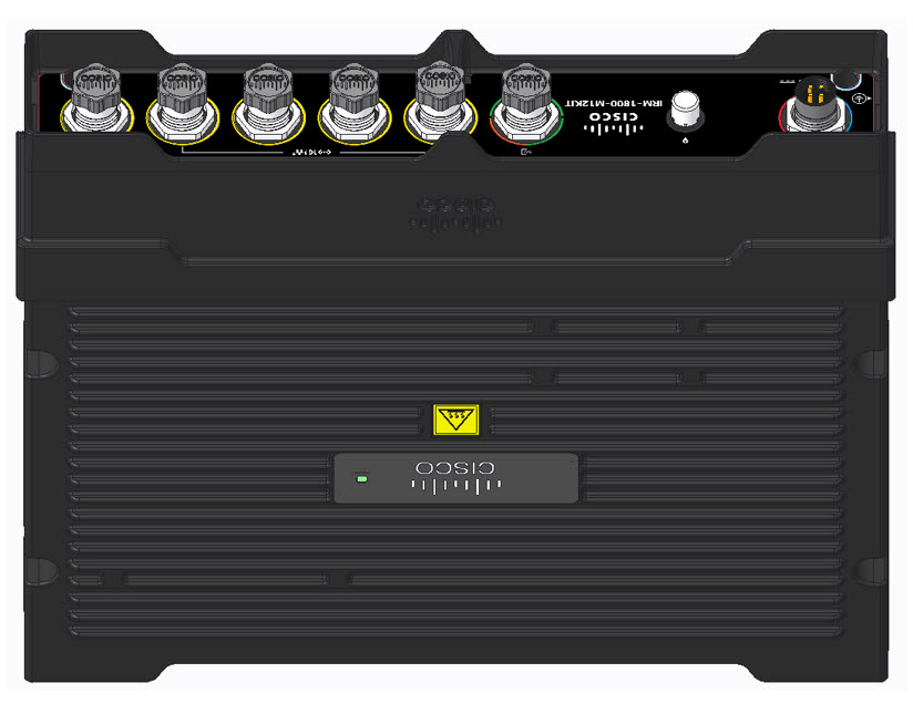
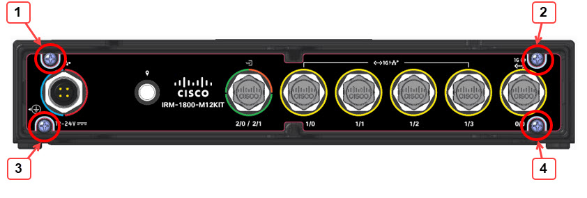
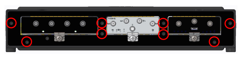
The M12 kit consists of two major pieces. The front panel contains all of the M12 connectors. The back panel covers the access for the pluggable modules.

 Note |
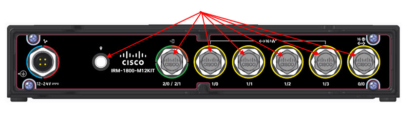
The M12 front panel comes with dust covers on all ports except the power connector. If a port is unused, make sure to leave the cover in place. |

Background on M12 Connectors
Introduced in 1985, the M12 connector has a long track record as one of the most reliable connectors for industrial applications. Once used primarily by automobile manufacturers, the M12 has become the industry standard in factory automation, autonomous robotics, communication, measurement and control, and many other applications.
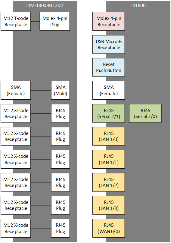
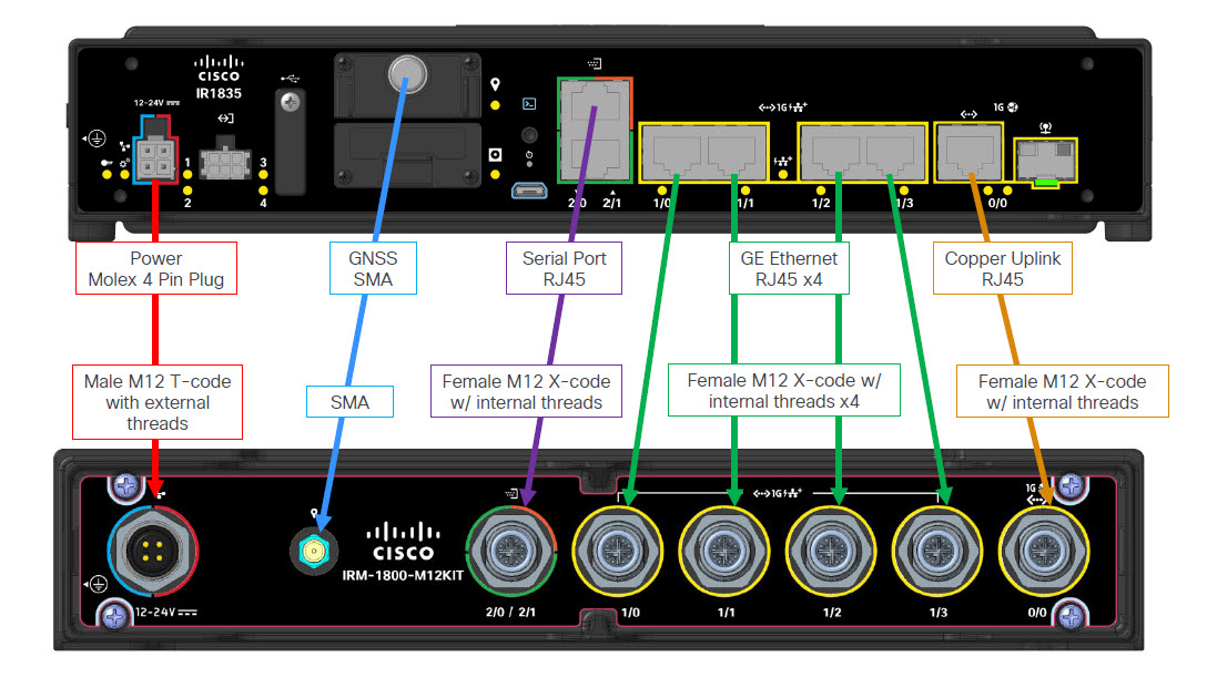
M12 connectors are found at multiple levels in automation, several styles of coding exist to prevent incorrect mating on products. The connectors used for the M12 kit on the IR1800 are:
-
One M12 male with external threads T-coded to Mini-Fit Jr plug for power and CAN interface
-
One SMA female to SMA male for the GNSS/Dead-Reckoning module
-
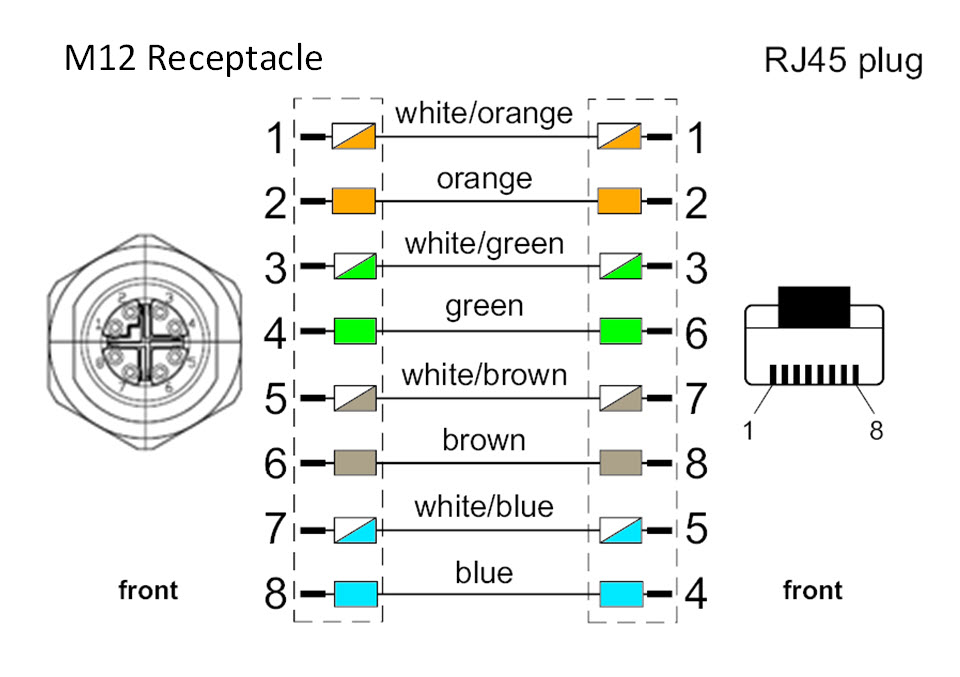
One M12 female with internal threads X-coded to RJ45 plug for serial ports
-
Five M12 female with internal threads X-coded to RJ45 plug for the GE WAN and LAN ports
Connector Details
The following figures show the M12 connector details:


|
1 |
DC- (GND-) |
|
2 |
CAN_P (CAN+) |
|
3 |
CAN_N (CAN-) |
|
4 |
DC+ (12V, 24V) |
SMA Connector
The SMA cable for the GNSS/Dead-Reckoning Interface is an SMA Female to SMA Male connector.


 Feedback