Cisco Wi-Fi Interface Module (WIM)

This chapter contains the following sections:

Overview

This section provides an overview of the Cisco Wi-Fi Interface Module (WIM). The PID is WP-WIFI6-x where x signifies the regulatory domain.

Highlights of the WIM are:

  • Pluggable 802.11ax module for Cisco Catalyst IR1800 series

  • WiFi-6 (802.11ax), 2x2 MIMO with 2 spatial streams

  • Extended Temperature Range

  • Field Replaceable Unit (FRU), however does not support OIR (Online Insertion and Removal)

  • Versatile RF coverage with external RP-SMA antenna connectors

  • Flexible Antenna Port feature support

  • Based on the Cisco AP 9105AXI

The following graphic shows the front panel of the WIM.

Table 1. WIM Front Panel

Item

Description

1

Disabled when the flexible antenna ports are set to dual-band mode (Default).

2.4 GHz when the flexible antenna ports are set to single-band mode.

2

Disabled when the flexible antenna ports are set to dual-band mode (Default).

2.4 GHz when the flexible antenna ports are set to single-band mode.

3

2.4/5 GHz when the flexible antenna ports are set to dual-band mode (Default).

5 GHz only when the flexible antenna ports are set to single-band mode.

4

2.4/5 GHz when the flexible antenna ports are set to dual-band mode (Default).

5 GHz only when the flexible antenna ports are set to single-band mode.

5

Enable LED

6

Wi-Fi LED

The following table describes the Enable LED:

LED Status

Description

Off

No Power

Yellow

Power is on, module is not yet functional

Green

Module is fully functional

The following table describes the Wi-Fi LED:


Note


LED status information is not applicable to concurrent radio mode. Concurrent radio Root AP + wireless client displays the default LED behavior — Alternate blinking red/green.

LED Status

Status Type

Description

Solid Green

Association Status

Normal operating condition, but no wireless client associated.

Solid Blue

Association Status

  • WP-WIFI6 (CAPWAP mode):

    Infra AP registered with WLC, Client connected to the AP

  • WP-WIFI6 (UIW WGB):

    1 — WGB registered with Infra AP

    2 — Both Radio Root AP(second radio) + wireless client connected: NA

Solid Green

Boot Loader Status

Executing Boot Loader

Flashing Green

Boot Loader Status

Boot Loader Error, signing verification error.

Flashing Blue

Operating Status

Software upgrade in progress.

Alternate between Green and Red

Operating Status

Discovery/Join process is in progress.

Cycle through Red-Off-Green-Off-Blue-Off

Access Point operating system error

General warning; insufficient inline power.

Installation

The Cisco Wi-Fi Interface Module remove and replace options are shown in the following steps.

The Router may have a blank plate covering the Wi-Fi Interface Module slot. This will need to be removed prior to installing the Wi-Fi Interface Module. The following example shows the Wi-Fi Interface Module.

Procedure


Step 1

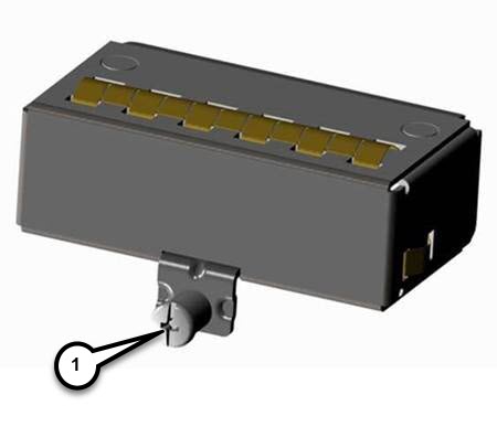
Remove the blank plate by unscrewing the latch lock screw(1 ) that holds the plate secure. Refer to the following graphic.

Figure 1. Latch Lock Screw

Step 2

Slide the blank plate out of the device.

Step 3

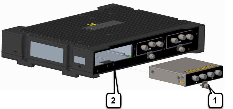
Slide the Wi-Fi Module into the device as shown in the following graphic. The latch lock screw (1 ) aligns with the screw hole (2 ) on the face of the device. Push the Wi-Fi Module all the way into the device until you feel it seat, and then torque the latch lock screw 8-10 inch-pound (0.9 to 1.1 newton meter).

Figure 2. Wi-Fi Module Insert

Step 4

Attach your antennas to the ports on the Wi-Fi module. There are different instructions for each antenna type, be sure to consult the antenna documentation for proper orientation and torque to install them.

Step 5

If no antennas are being installed on a port, make sure the caps are installed on the connector.


Transmit Power and Receive Sensitivity

The following series of tables provide details for the transmit power and receive sensitivity.

Table 2. 802.11/11b

5 GHz Radio

2.4 GHz Radio

Spatial Streams

Number of Active Antennas

Total TX power (dBm)

RX sensitivity (dBm)

Total TX power (dBm)

RX sensitivity (dBm)

1 Mbps

1

2

23

-97

11 Mbps

1

2

23

-88

Table 3. 802.11a/g

5 GHz Radio

2.4 GHz Radio

Spatial Streams

Number of Active Antennas

Total TX power (dBm)

RX sensitivity (dBm)

Total TX power (dBm)

RX sensitivity (dBm)

6 Mbps

1

2

20

-93

21

-92

24 Mbps

1

2

20

-86

21

-86

54 Mbps

1

2

19

-77

21

-78

Table 4. 802.11n HT20

5 GHz Radio

2.4 GHz Radio

Spatial Streams

Number of Active Antennas

Total TX power (dBm)

RX sensitivity (dBm)

Total TX power (dBm)

RX sensitivity (dBm)

MCS0

1

2

20

-93

21

-92

MCS15

2

2

19

-71

21

-73

Table 5. 802.11n HT40

5 GHz Radio

2.4 GHz Radio

Spatial Streams

Number of Active Antennas

Total TX power (dBm)

RX sensitivity (dBm)

Total TX power (dBm)

RX sensitivity (dBm)

MCS0

1

2

20

-90

MCS15

2

2

19

-68

Table 6. 802.11ac VHT20

5 GHz Radio

2.4 GHz Radio

Spatial Streams

Number of Active Antennas

Total TX power (dBm)

RX sensitivity (dBm)

Total TX power (dBm)

RX sensitivity (dBm)

MCS0

1

2

20

-93

MCS8

1

2

18

-70

MCS0

2

2

20

-90

MCS8

2

2

18

-67

MCS9

2

2

Table 7. 802.11ac VHT40

5 GHz Radio

2.4 GHz Radio

Spatial Streams

Number of Active Antennas

Total TX power (dBm)

RX sensitivity (dBm)

Total TX power (dBm)

RX sensitivity (dBm)

MCS0

1

2

20

-90

MCS9

1

2

17

-66

MCS0

2

2

20

-87

MCS9

2

2

17

63

Table 8. 802.11ac VHT80

5 GHz Radio

2.4 GHz Radio

Spatial Streams

Number of Active Antennas

Total TX power (dBm)

RX sensitivity (dBm)

Total TX power (dBm)

RX sensitivity (dBm)

MCS0

1

2

20

-87

MCS9

1

2

16

-63

MCS0

2

2

20

-84

MCS9

2

2

16

60

Table 9. 802.11ax HE20

5 GHz Radio

2.4 GHz Radio

Spatial Streams

Number of Active Antennas

Total TX power (dBm)

RX sensitivity (dBm)

Total TX power (dBm)

RX sensitivity (dBm)

MCS0

1

2

20

-94

20

-92

MCS11

1

2

16

-63

15

-66

MCS0

2

2

20

-92

20

-91

MCS11

2

2

16

60

15

62

Table 10. 802.11ax HE40

5 GHz Radio

2.4 GHz Radio

Spatial Streams

Number of Active Antennas

Total TX power (dBm)

RX sensitivity (dBm)

Total TX power (dBm)

RX sensitivity (dBm)

MCS0

1

2

20

-91

MCS11

1

2

16

-60

MCS0

2

2

20

-88

MCS11

2

2

16

-57

Table 11. 802.11ax HE80

5 GHz Radio

2.4 GHz Radio

Spatial Streams

Number of Active Antennas

Total TX power (dBm)

RX sensitivity (dBm)

Total TX power (dBm)

RX sensitivity (dBm)

MCS0

1

2

20

-88

MCS11

1

2

16

-57

MCS0

2

2

20

-85

MCS11

2

2

16

-54

Thermal Mitigation

The following table provides a description of thermal mitigation levels and throughput performance.

This applies to the IR1835 with dual P-LTEAP18-GL pluggable modules and the WP-WIFI6 pluggable module.

Table 12. Thermal Mitigation Table - IR1835

Hardware

Maximum Ambient Temperature (C/F)

Airflow (LFM)

Throughput Performance

IR1835 plus WP-WIFI6 Dual P-5GS6-GL

60°/140°

0

Throttled, 1x1 SISO

65°/149°

40

Throttled, 1x1 SISO

70°/158°

200

Throttled, 1x1 SISO

The WP-WIFI6 pluggable will experience normal operation up to 55°C /131°F. Under normal conditions both 2.4 and 5 GHz radios of the WP-WIFI6 pluggable operate in 2x2 MIMO mode, with antenna ports A and B active. Upon exceeding the ambient temperature and airflow levels indicated in the thermal mitigation table, both 2.4 and 5 GHz radios may throttle to 1x1 SISO. In 1x1 SISO mode only antenna port A is active, and each radio is restricted to single spatial stream data rates.