Product Overview

This chapter contains the following sections:

Overview of Features

This chapter provides an overview of the features available in the Cisco Catalyst IR1800 Rugged Series Router (referred to as the IR1800 in the rest of this document).

The IR1800 is a next-generation modular industrial router based on Cisco IOS-XE, with advanced features such modular Wi-Fi, modular cellular WAN, Controller Area Network (CAN bus), solid-state drive (SSD), digital I/O, and GPS dead reckoning.

The IR1800 features a base platform with modularity that includes:

  • Pluggable Interface Module (PIM) slot(s)
  • Wi-fi Interface Module (WIM) slot
  • SSD Module slot
  • GPS Module slot

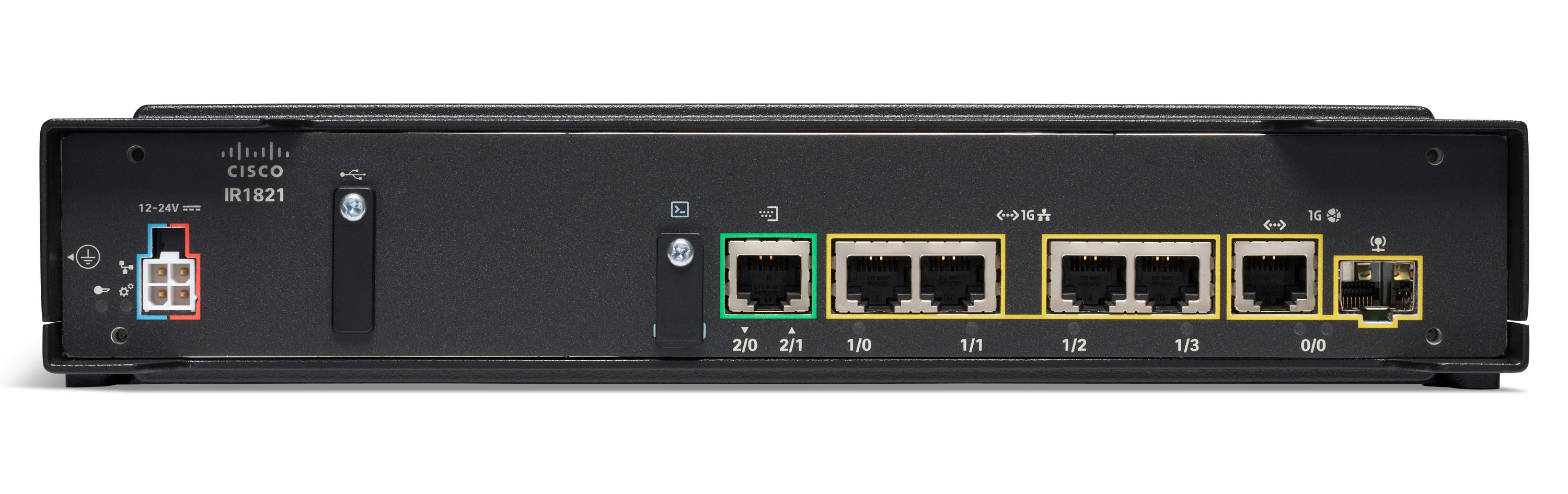
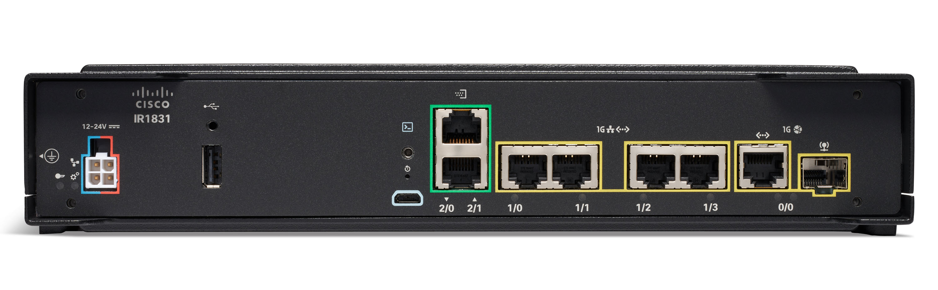
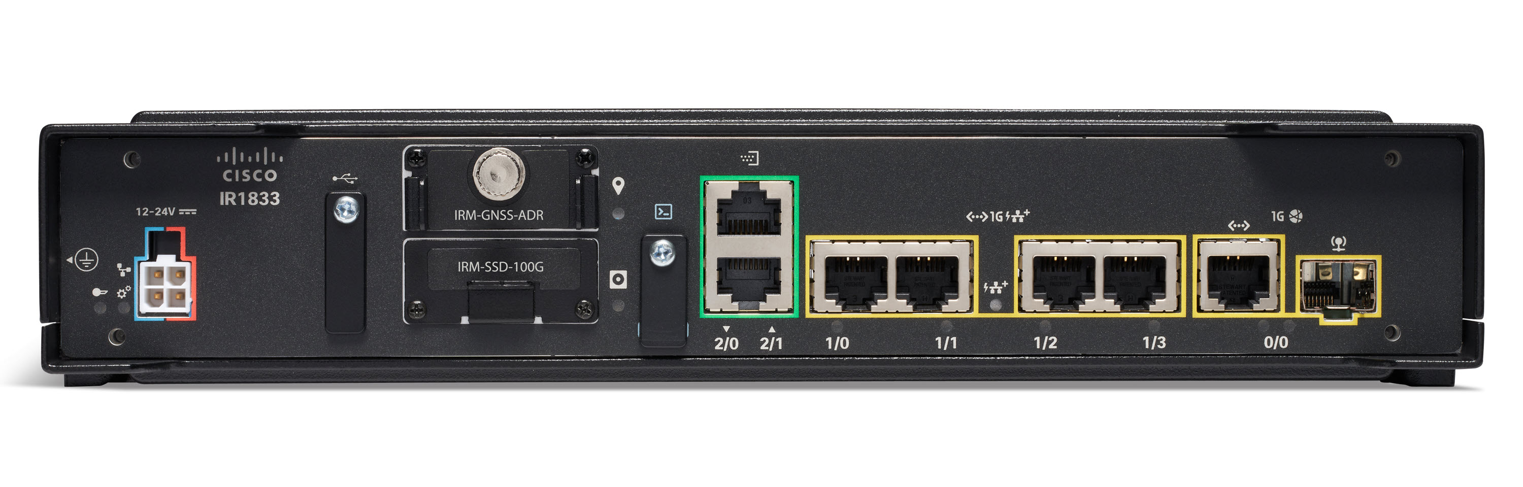
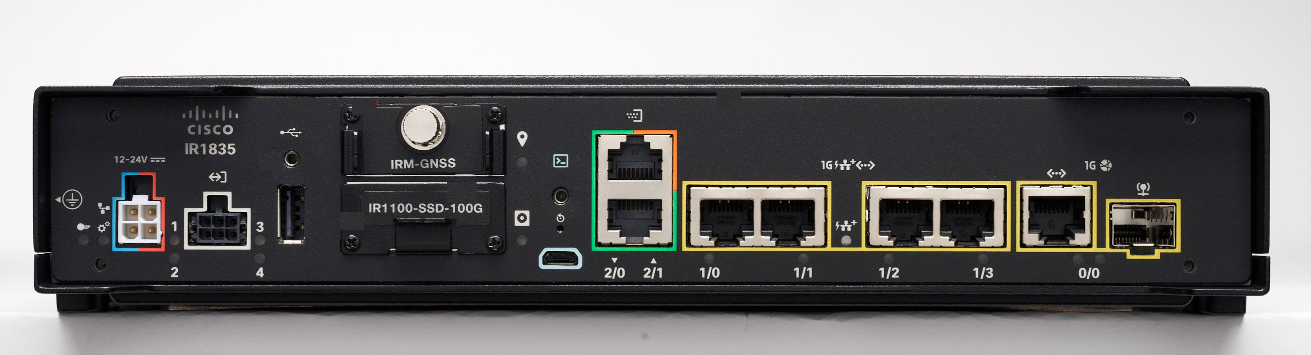
The IR1800 consists of four SKUs:

  • IR1821
  • IR1831
  • IR1833
  • IR1835

The following table shows the differences among the features of these SKUs.

Table 1. Differences in IR1800 SKU Features

Feature

IR1821

IR1831

IR1833

IR1835

Processor Frequency

600 MHz

600 MHz

600 MHz

1200 MHz

DDR Memory

4GB

4GB

4GB

8GB

Flash Storage

4GB

4GB

4GB

8GB

PIM Slot

1

2

2

2

Wi-Fi Pluggable Module Slot

1

1

1

1

PoE

No

No

Yes

Yes

SSD Module Slot

No

No

Yes

Yes

GPS FRU Module Slot

No

No

Yes

Yes

Digital I/O

No

No

No

Yes

Asynchronous Serial Interface

(1) RS232 DTE

(1) RS232 DTE

(1) RS232 DCE

(1) RS232 DTE

(1) RS232 DCE

(1) RS232 DTE

(1) RS232 DCE/RS485

Cisco IR1800 Series Platform Features

This section describes the different components of the router.

Cisco IR1821 Router

Figure 1. Cisco IR1821 Router

Cisco IR1831 Router

Figure 2. Cisco IR1831 Router

Cisco IR1833 Router

Figure 3. Cisco IR1833 Router

Cisco IR1835 Router

Figure 4. Cisco IR1835 Router

Front Panel Overview

This section describes the components of the IR1800 router. The IR1835 is used as an example since this SKU is the full featured router.

Table 2. Front Panel of the IR1835 Router

Item

Description

1

Power Connector/CAN Bus High/Low wiring

2

Digital I/O connector with Ignition Wiring

3

Type A USB 2.0

4

GPS FRU Module

5

SSD FRU Module

6

Reset Button

7

USB Console (Micro-B)

8

Asynchronous Serial Ports

9

Gigabit Ethernet LAN ports 0/1/0-0/1/1

10

Gigabit Ethernet LAN ports 0/1/2-0/1/3

11

Gigabit Ethernet 0/0/0 WAN Combo Ports (RJ-45 or SFP)

Rear Panel Overview

This section describes the components of the IR1800 router. The IR1835 is used as an example since this SKU is the full featured router.

Item

Description

1

Wi-Fi Interface Module (WIM) 0/3/0

2

Pluggable Interface Module 0/4/0 (PIM)

3

Pluggable Interface Module 0/5/0 (PIM)

Pluggable Modules

The following subsections provide details on the different modules that can be plugged into the IR1800 Series Routers.

Cellular Pluggable Interface Module (PIM)

The Cellular Pluggable Interface Module (PIM) is a pluggable unit used to connect to a wireless (LTE) interface. For more information about the PIM, see Pluggable Interface Modules.

SSD Module

The IR1800 supports one Solid State Drive (SSD) module. For more information see SSD Module.

GPS Module

The IR1800 supports one GPS module. This module is used in addition to the ones integrated in the pluggable LTE module for more accurate dead reckoning performance.

For more information about the module see GPS Field Replaceable Unit Module .

SFP Modules


Warning


Class 1 laser product. Statement 1008


The IR1800 Ethernet SFP module provides connections to other devices. These field-replaceable transceiver modules provide uplink interfaces. Local connectors provide the fiber-optic connection. RJ-45 connectors allow copper connections. You can use any combination of the supported SFP modules listed in the following table.

Table 3. Supported Gigabit Ethernet SFPs

Gigabit Ethernet SFP

Distance

Fiber

Commercial

0C to +70C

Extended

-5C to +85C

Industrial

-40C to +85C

Digital Optical Monitoring

GLC-SX-MM-RGD

220-550 m

MMF

YES

GLC-LX-SM-RGD

550m/10 km

MMF/SMF

YES

GLC-ZX-SM-RGD

70 km

SMF

YES

YES

SFP-GE-S

220-550 m

MMF

YES

YES

SFP-GE-L

550 m/10 km

MMF/SMF

YES

YES

SFP-GE-Z

70 km

SMF

YES

YES

Table 4. Supported Fast Ethernet SFPs

Fast Ethernet SFP

Distance

Fiber

Commercial

0C ~ +70C

Extended

-5C ~ +85C

Industrial

-40C ~ +85C

Digital Optical Monitoring

GLC-FE-100FX-RGD

2 km

MMF

YES

GLC-FE-100LX-RGD

10 km

SMF

YES

Table 5. Supported SFPs added in IOS XE 17.7.1

SFP

Distance

Fiber

Commercial

0C ~ +70C

Extended

-5C ~ +85C

Industrial

-40C ~ +85C

Digital Optical Monitoring

GLC-T-RGD

100 M

Copper

YES

CWDM-SFP-1470

100 km

Duplex

YES

YES

CWDM-SFP-1610

100 km

Duplex

YES

YES

CWDM-SFP-1530

100 km

Duplex

YES

YES

DWDM-SFP-3033

80 km

Duplex

YES

YES

DWDM-SFP-3112

80 km

Duplex

YES

YES

GLC-BX-D-I

10 km

Single Strand

YES

YES

GLC-BX-U-I

10 km

Single Strand

YES

YES

GLC-TE

100 m

Copper

YES

NO

For the most up-to-date list of supported SFP models for Cisco Industrial Devices, see the Cisco Optics-to-Device Compatibility Matrix.

Gigabit Ethernet Combo Port

The IR1800 supports a single combo fiber and copper port (SFP/RJ45). The SFP supports standard 1000Base-X or 100Base-FX Ethernet over single-mode or multi-mode optics. Industrial SFPs must be used for the system to meet the operating temperature from -40C to +60C. If commercial or extended temperature grade of SFP is used, the system's operating temperature must be derated.

Gigabit Ethernet Copper Ports

The IR1800 has four RJ-45 copper ports. These copper ports support standard 3-speed, 10/100/1000Base-T Ethernet features, including automatic medium-dependent interface crossover (auto-MDIX), forced or auto negotiation of speed and duplex, fast link drop, and cable diagnostics.

Power over Ethernet

A 30.8W capacity PoE PSE power supply is built into the IR1800. The power supply can power any of the LAN switch ports that are compliant with PoE and PoE+ 802.3af and 802.3at Powered Device (PD) specification, subject to 30.8 W maximum power shared among all ports.

Front Panel LEDs

The following figure shows the locations of the LEDs.

Table 6. LED Descriptions

LED Number

Description

LED Status

1

Ignition Status

Off: Ignition power management is disabled when SYS LED is on.

Steady Green combined with SYS LED Off: Ignition signal is off (power management is enabled).

Steady Green combined with SYS LED On: Ignition signal is on.

Flashing Green with Ignition Off: Timer counts down when SYS LED is on.

Steady Yellow: Ignition power management feature is not loaded.

2

System Status

Note

 
There is also a System Status LED located on the top cover of the device. The Front panel LED and the Top Cover LED perform the same function. (see the Top Cover LED below)

Steady Green: Operational.

Flashing Green: Cisco IOS-XE booting.

Steady Yellow: System in ROMMON mode.

Off: No power.

3 and 4

Digital I/O

Off: Inactive.

Steady Yellow: Active.

5

GPS Module

Steady Green: GPS/DR configured; location fix achieved.

Flashing Green: GPS DR active; trying to achieve location fix.

Off: GPS DR not configured.

6

SSD Module

Steady Green: SSD is being accessed.

Off: No power or is not enabled.

7

Four Gigabit Ethernet LAN ports labeled 1/0, 1/1, 1/2, 1/3

Note

 
See the IR1800 Software Configuration Guide for Cisco IOS-XE naming conventions.

Steady Green: Port is up with link.

Flashing Green: Link with activity.

Off: Port is off or down.

8

PoE Power Status

Steady Green: POE or POE+ power supplied on one LAN Port.

Off: No POE or POE+ power in any LAN port.

9

RJ45 Gigabit Ethernet WAN

Note

 
Either the SFP or the RJ45 LED will be On, depending on what type of interface is used in the combo port.

Steady Green: Port is up with link.

Flashing Green: Link with activity.

Off: No link, or port is off.

10

SFP Gigabit Ethernet WAN

Note

 
Either the SFP or the RJ45 LED will be On, depending on what type of interface is used in the combo port.

Steady Green: Port is up with link.

Flashing Green: Link with activity.

Off: No link, or port is off.

Figure 5. Top Cover LED

Reset Button

The Reset button resets the router configuration to the default factory configuration. To perform the reset, use a standard size #1 paper clip with wire gauge 0.033 inch or smaller, and simultaneously press the Reset button while applying power to the router.


Note


The reset button does not cause a reset while the device is running.

Supported Cisco Antennas and Antenna Accessories

The IR1800 must have a pluggable module with antenna ports installed in order to connect to antennas. The base unit does not have any wireless capabilities on its own.

The Chapter Antenna Selection and Installation lists the supported antennas and accessories for the IR1800 with a wireless pluggable module. For detailed information about Cisco antennas for industrial routers, see the Cisco Industrial Routers and Industrial Wireless Access Points Antenna Guide.


Note


We strongly recommend against having antennas attached directly to the router. It is better to use cables attached directly to the router.

Modem Support

Software download for the pluggable modules supported in the IR1800 is available at:

https://software.cisco.com/download/navigator.html?mdfid=286288566&flowid=76082

The following tables show the technology details for the modems.

Table 7. Modem Technology Supported

SKU ID

Description

Supported Technology

P-LTE-VZ

U.S. (Verizon) Single Micro SIM

LTE CAT4: B4, B13

P-LTE-US

North America (AT&T) Dual Micro SIM

LTE CAT4: B2, B4, B5, B12

HSPA+,UMTS: B2, B4, B5

P-LTE-GB

Europe Dual Micro SIM

LTE CAT4: B3, B5, B8, B20, B28

HSPA+: B1, B5, B8

EDGE: 900/1800

P-LTE-IN

India and China

LTE CAT4: B1, B3, B5, B8, B40, B41*

* B41—supported frequency range: (2535–2655 MHz)

3G UMTS DC-HSPA+

P-LTE-MNA

North America

LTE CAT4: B2, B4, B5, B12, B13, B14, B17, B66

3G UMTS DC-HSPA+, HSPA+, HSPA, WCDMA

P-LTEA-LA

APAC

LTE Bands: B1, B3, B5, B7, B8, B18, B19, B21, B28, B38, B39, B40, B41

Non-LTE Bands: B87 - WCDMA (Europe, Japan, and China) 2100 band

B91 - WCDMA US 850 band

B92 - WCDMA Japan 800 band

B114 - WCDMA Europe and Japan 900 band

B115 - WCDMA Japan 1700 band

B125 - WCDMA Japan 850 band

P-LTEA-EA

USA, Canada, Europe, Latin America

LTE bands: Bands 1-5, 7, 12, 13, 20, 25, 26, 29, 30

Non-LTE bands: B87 - WCDMA (Europe, Japan, and China) 2100 band

B88 - WCDMA US PCS 1900 band

B89 - WCDMA (Europe and China) DCS 1800 band

B90 - WCDMA US 1700 band

B91 - WCDMA US 850 band

B114 - WCDMA Europe and Japan 900 band

P-LTEAP18-GL

United States, Europe, Canada, Japan, Australia, New Zealand and Private LTE or U.S. CBRS

LTE bands: 1-5, 7, 8, 12-14, 17, 18-20, 25, 26, 28-30, 32, 38-43, 46, 48, 66, and 71.

FDD LTE 600 MHz (band 71), 700 MHz (bands 12, 13, 14, 17, 28, and 29), 800 MHz (band 20), 850 MHz (bands 5, 18, 19, and 26), 900 MHz (band 8), 1500 MHz (band 32), 1700 MHz (bands 4 and 66), 1800 MHz (band 3), 1900 MHz (bands 2 and 25), 2100 MHz (band 1), 2300 MHz (band 30), 2600 MHz (band 7).

TDD LTE 1900 MHz (band 39), 2300 MHz (band 40), 2500 MHz (band 41), 2600 MHz (band 38), 3500 MHz (bands 42 and 48), 3700 MHz (band 43), 5200 MHz (band 46).

P-5GS6-GL

The 5G Sub-6 GHz Pluggable Interface Module offers 5G capability to the IoT Industrial Router family. The product ID for the pluggable module is P-5GS6-GL. The P-5GS6-GL uses the FN980 Telit modem.

Complete details can be found in the 5G Sub-6 GHz Pluggable Interface Module chapter.

P-LTEA7-NA

North America

LTE CAT 7: B2, B4, B5, B7, B12, B13, B14, B25, B26, B41, B42, B43, B48, B66, B71

3G UMTS, WCDMA: B2, B4, B5

P-LTEA7-EAL

Canada, Europe, Latin America, US

LTE CAT 7: B1, B3, B7, B8, B20, B28, B32, B38, B40, B41, B42, B43

3G UMTS, WCDMA: B1, B5, B8

P-LTEA7-JP

Japan

LTE CAT 7: B1, B3, B5, B8, B18, B19, B39, B41, B42, B43

3G UMTS, WCDMA: B1, B5, B6, B19

Table 8. Thermal Mitigation Table for P-LTEA7-XX modules - IR1835
MaximumAmbient Temperature (C/F) AirFlow (LFM)

ThroughputPerformance

IR1835plus WP-WIFI6

Single P-LTEA7-XX

50℃/122℉

0

Normal

55℃/131℉

0

Throttled

70℃/158℉

40

Throttled

75℃/167℉

200

Throttled

GPS Technology Support

The IR1800 obtains GPS service through either the installed PIM modules, or from the dedicated IRM-GNSS-ADR module. Please inquire with your sales representative for a roadmap of support for additional constellations.

Power Supply

IR1800 comes with an external DC power connector. The 4-pin power entry connector (receptacle) is mounted to the unit. The 4-pin power-entry mating connector (plug) is attached to the receptacle. It is removed during installation and used to connect to the DC power source, and then reattached to provide power to the unit.

For more information, see Connecting the Router.

Serial Ports

IR1800 supports up to two RJ-45 RS232 ports (depending on the model) that conform to EIA-561 standard. The pinout is shown in the table below.

One RS232 RJ45 serial port (S0) is intended as a DTE port supporting legacy RS232 equipment. The second serial port (S1) is intended as a DCE port, capable of both RS232 and RS485. RS485 can support full or half duplex.

The RJ45 pinouts are shown in the following figure and table:

Figure 6. Pinouts
Table 9. Serial Port Characteristics
RS232 RS485 Full Duplex RS485 Half Duplex

Pin #

Signal Description

Abbr.

S0 (DTE)

S1 (DCE)

Signal

DIR

Signal

DIR

1

DCE ready.

Used as DSR in Cisco IOS.

DSR/RI

Input

Output

TX-

Output

TX/RX+

<->

2

Received Line Signal Detector

DCD

Input

Output

TX+

Output

TX/RX-

<->

3

DTE Ready

DTR

Output

Input

RX-

Input

4

Signal Ground

COM

COM

COM

5

Received Data

RxD

Input

Output

6

Transmitted Data

TxD

Output

Input

RX+

Input

7

Clear To Send

CTS

Input

Output

8

Request To Send

RTS

Output

Input

USB Ports

A single USB port with a Type-A connector is present on the front panel. The port is USB 2.0 only, and can be used for USB sticks. We recommend that you do not use this in a hazardous location without mechanical constraint. All front panel USB ports are equipped with a screw hole for mechanical constraint. The USB port can provide a maximum current of 500mA at 5V.

A single USB port (micro-B) is provided for console access on the front panel. If your laptop or PC displays a message that you do not have the proper drivers to communicate with the IR1800, you can obtain them from your computer manufacturer.


Caution


If you are connecting to the USB port, note the following points:
  • A connection to the USB port can only be made in a nonhazardous environment.

  • The USB port cover must be reinstalled before the router can be deployed in a hazardous environment.