Installing the IP54 Kit

This chapter contains the following sections:

Overview of the IP54 Kit

The IR1800 has a kit, which when installed, provides dust and water protection and discourages tampering.

The PID is IR1800-IP54-KIT.

Before you begin, make sure that you have completed all of the standard installation steps described in the earlier chapters of this guide.


Caution


The IP54 kit installed with the router is not intended to meet the Hazardous Locations IP54 requirement according to IEC 60079-7:2018, clause 23.

Caution


All the cabling that extends from the router and gets terminated elsewhere, that is, Power, Ethernet, Antenna, and so on, must have a minimum ingress protection rating of IP54 according to EN60529 when used in conjunction with the IP54 kit. It is the responsibility of the customer to ensure that all cabling and terminations outside of the router meet the required ingress protection requirement. In addition, the router is not designed for and should not be placed outdoors. The intent of the IP54 kit is to provide supplementary protection to the router against dust and occasional splashing water. Cisco cannot guarantee prolonged reliable operation of the router if these guidelines are violated.

Caution


Before beginning the installation of the IP54 kit, consider carefully whether the installation site is strong enough to support the combined weight of the IP54 enclosure and the router that it encloses.

The IP54 kit contains:

  • Front Cover Components

  • Back Cover

  • Screws to build the kit and attach it to IR1800

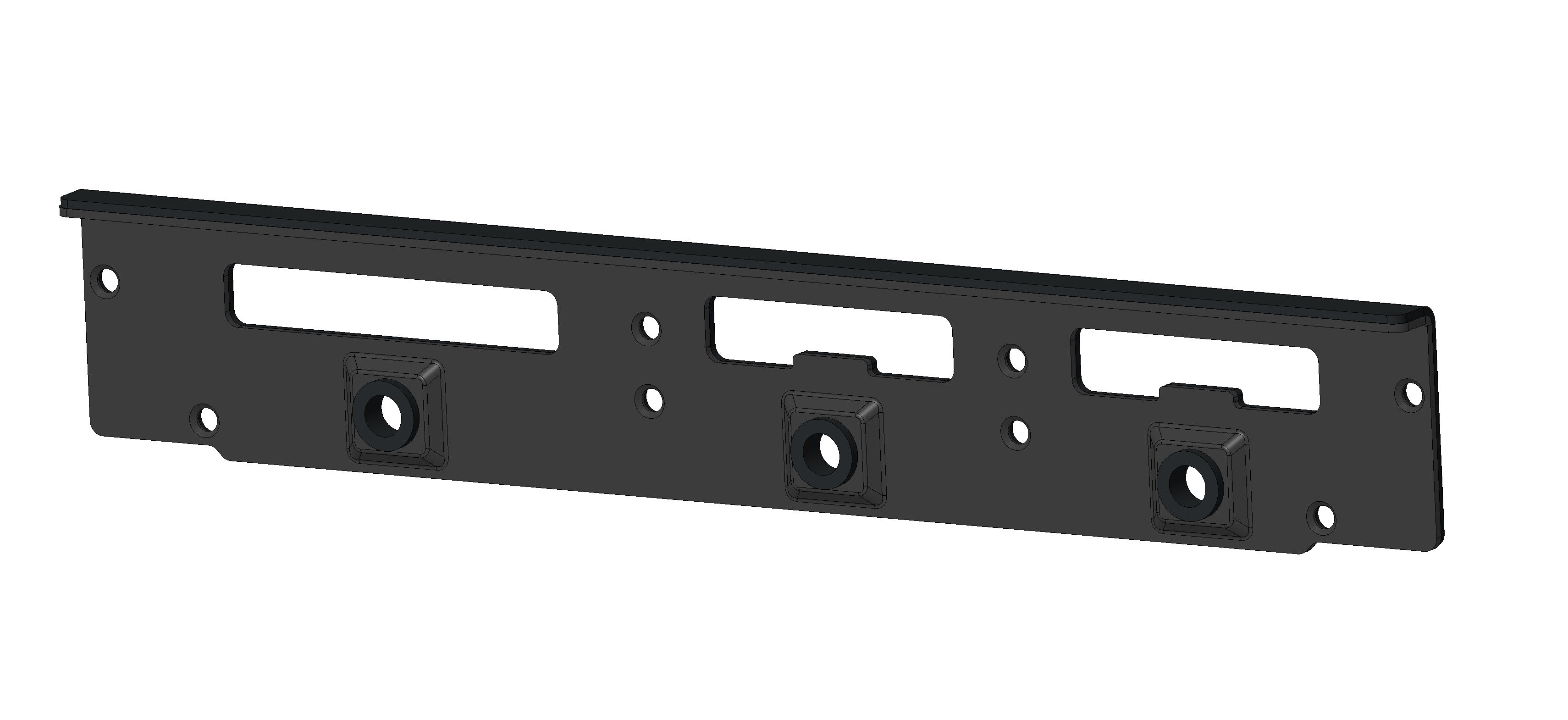
The front cover is shipped disassembled because it must be assembled onto the IR1800. The front cover comprises four parts.
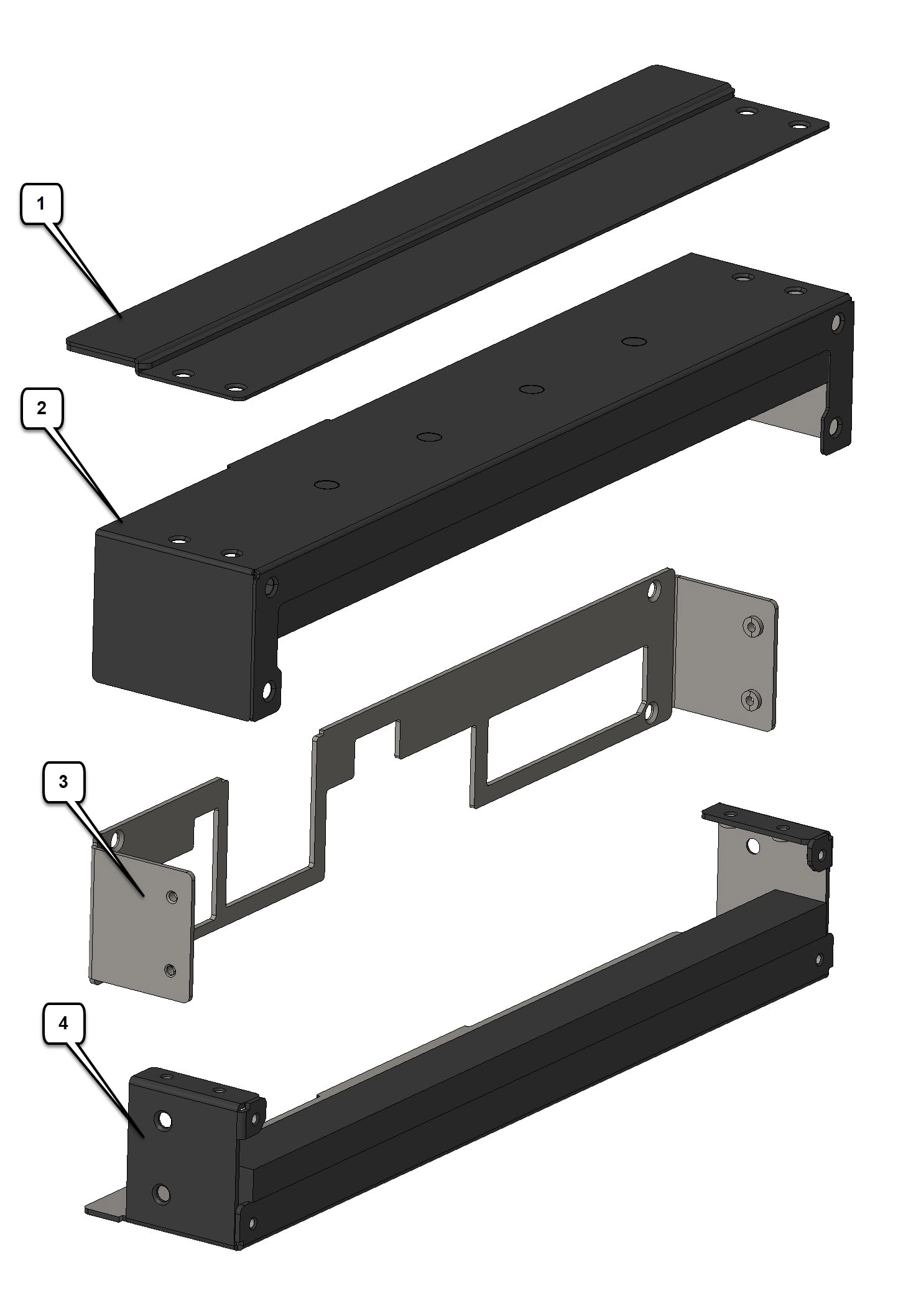
Figure 1. Front Cover Parts

1

Top Cover Plate

2

Top Cover

3

Mounting Plate

4

Bottom Cover

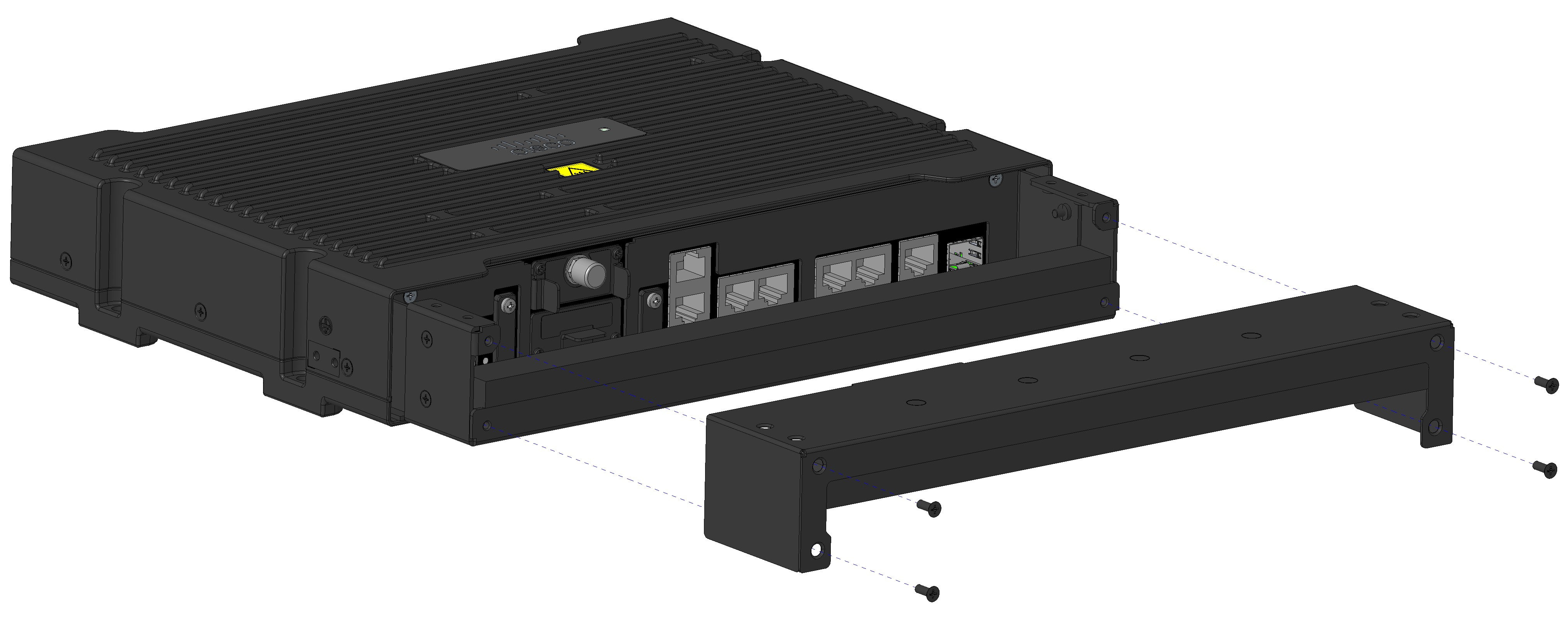
Figure 2. Back Cover Parts

The IP54 back cover ships as one piece with eight screws.

Installing the IP54 Kit

This section provides an overview of the IP54 kit installation.


Note


Ensure that you are using proper static discharge techniques such as a wrist strap and static mat.

Caution


Ensure the device is powered down before performing any removal or installation of a module.

Installing the Front Cover

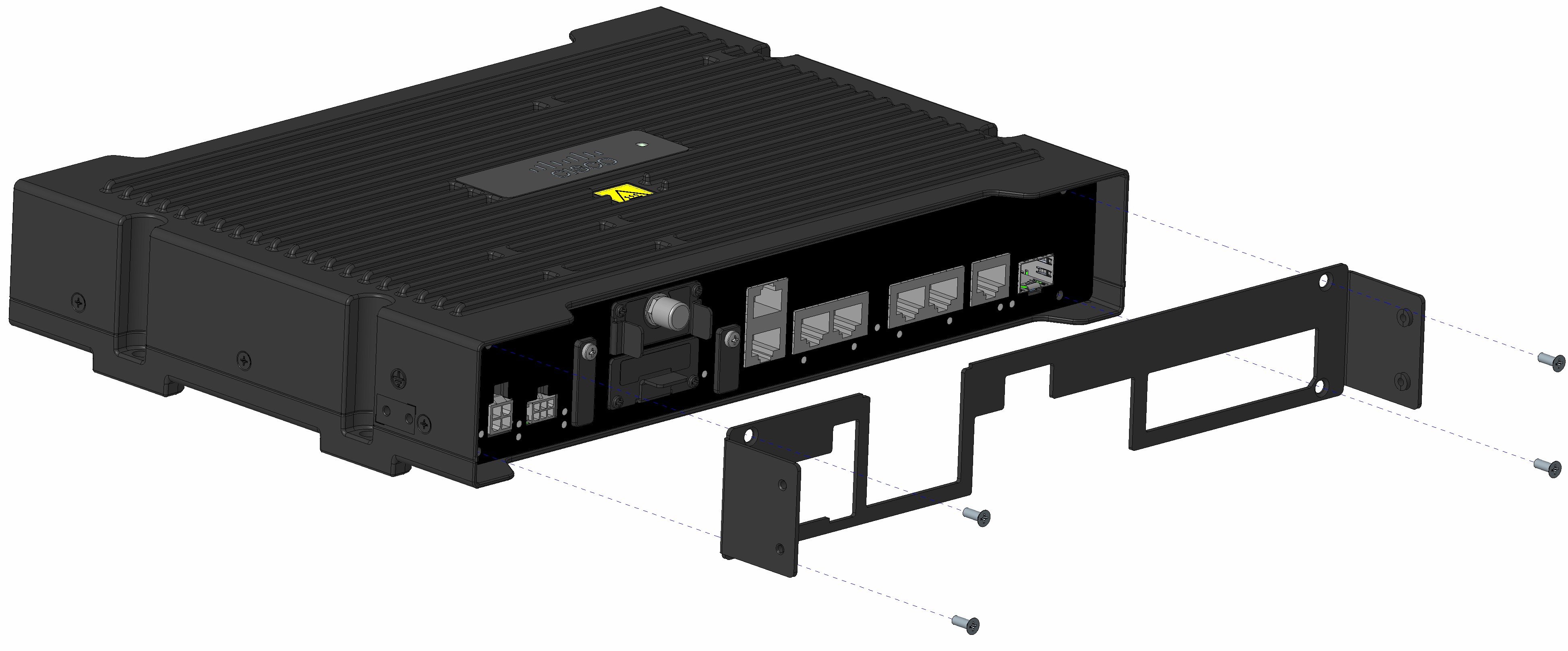
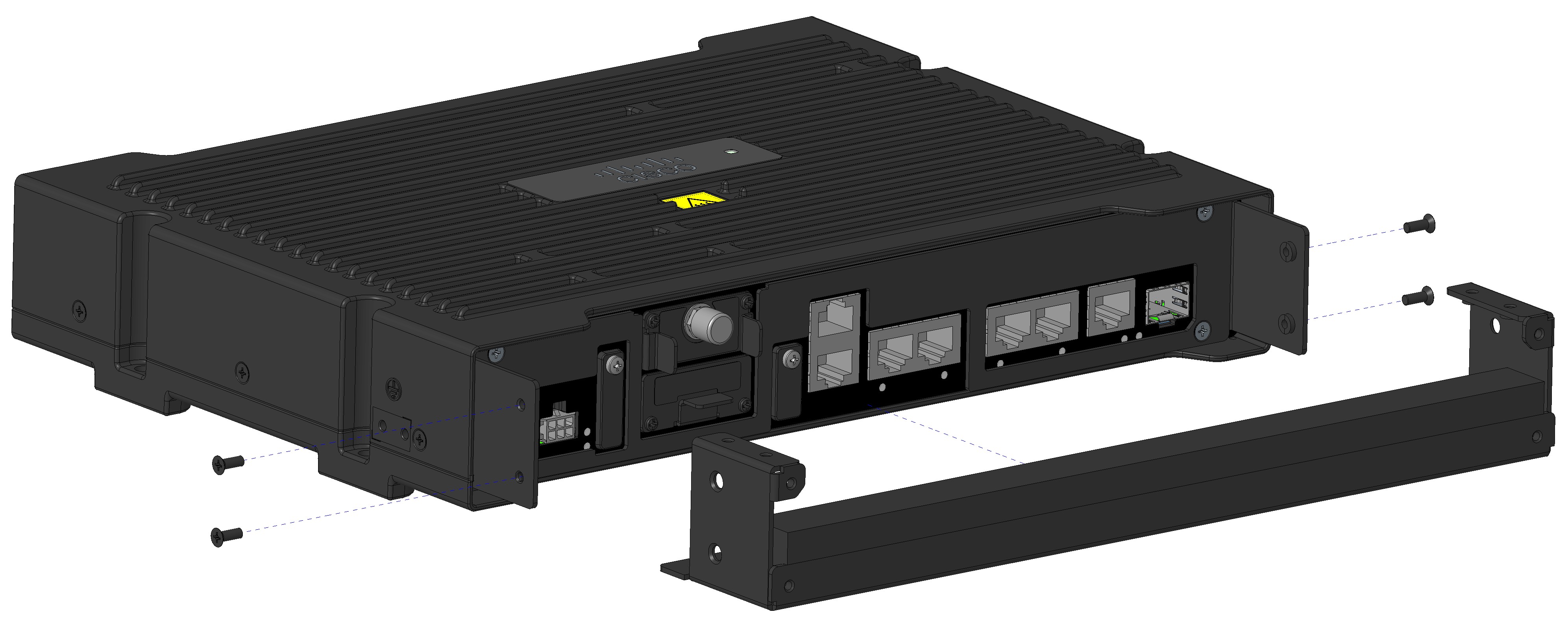
The front cover of the IP54 kit is installed around the IR1800 using the four parts previously listed and the screws provided.

Before you begin

Make sure all cables are removed and that the desired FRUs or blanks are installed before assembling the front IP54 cover.

Procedure


Step 1

Attach the mounting plate to the front of the chassis using four of the provided screws.

Step 2

Tighten the screws to a torque of 5 to 6 in-lbs.

Step 3

Attach the bottom cover to the mounting plate using four of the provided screws.

Step 4

Plug in the power and all other cables after the bottom cover is attached. Drape all the cables over the foam seat.

Step 5

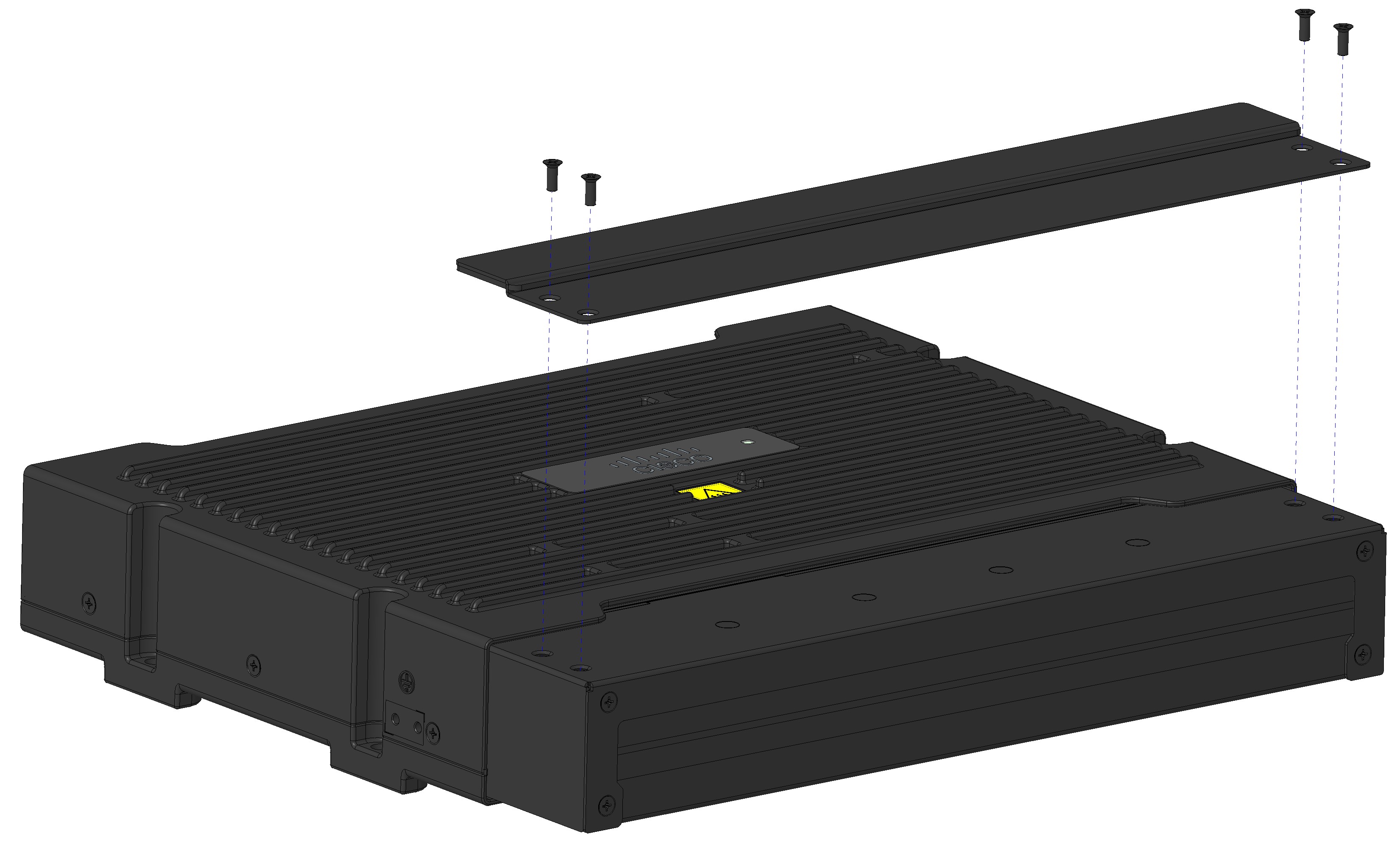
Attach the top cover to the bottom cover using four of the provided screws.

Note

 
All the cables should be wedged between the top and bottom foam pieces.

Step 6

Attach the top cover plate to the top cover using four more of the provided screws.

Step 7

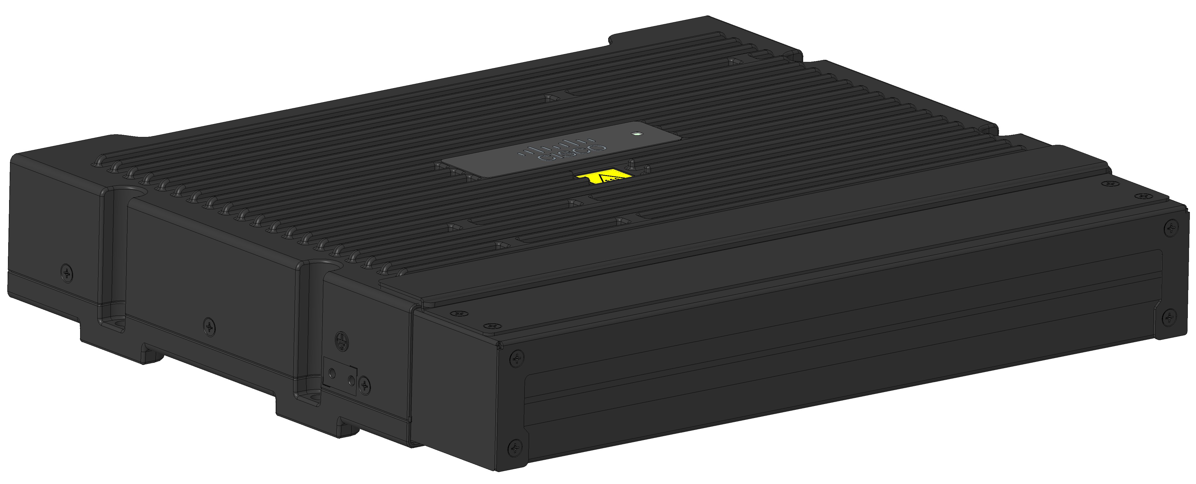
The following figure shows the final assembly.


Installing the Back Cover

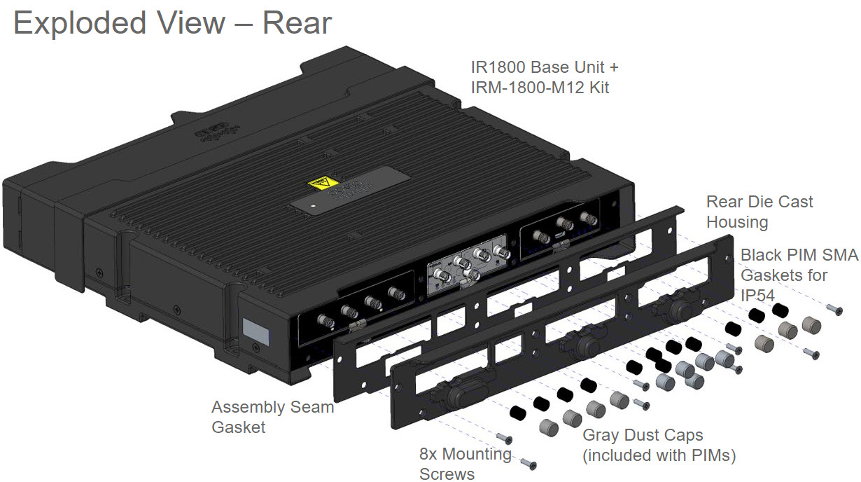
The back cover is installed as a single piece using eight screws provided.

Procedure


Step 1

Make sure that all the slots have pluggable modules or blanks, and that all the antennae are removed before attaching the back cover.

Note

 
If your pluggable module has a USB port cover attached, remove the cover. If the USB port cover is installed along with the IP54 back cover, it will interfere with the installation.

Step 2

Attach the back cover to the back of the chassis over the pluggable modules using eight of the provided screws.

Step 3

Tighten the screws to a torque of 5 to 6 in-lbs.

Step 4

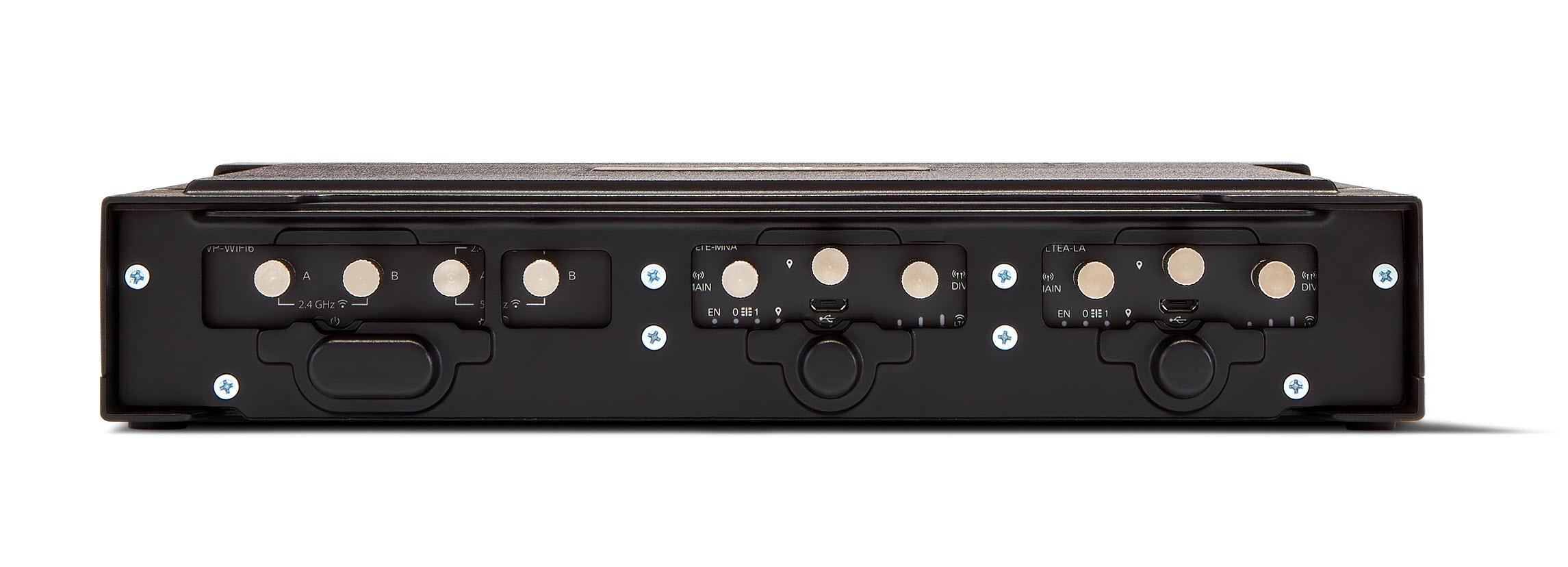
After the cover is in place, the antenna cables can be attached to the pluggable modules, as needed. The following figure shows the final assembly.