Segment Routing Configuration Guide for Cisco NCS 5500 Series Routers, IOS XR Release 24.1.x, 24.2.x, 24.3.x, 24.4.x
Bias-Free Language
The documentation set for this product strives to use bias-free language. For the purposes of this documentation set, bias-free is defined as language that does not imply discrimination based on age, disability, gender, racial identity, ethnic identity, sexual orientation, socioeconomic status, and intersectionality. Exceptions may be present in the documentation due to language that is hardcoded in the user interfaces of the product software, language used based on RFP documentation, or language that is used by a referenced third-party product. Learn more about how Cisco is using Inclusive Language.
This feature is now supported on Cisco NCS 5700 series fixed-port routers and the Cisco NCS 5500 series routers that have
the Cisco NC57 line cards installed and operating in the native mode.
To enable the native mode, use the hw-module profile npu native-mode-enable command in the configuration mode. Ensure that you reload the router after configuring the native mode.
Tree Segment Identifier (Tree-SID) is an SDN controller-based approach to build label switched multicast (LSM) Trees for efficient
delivery of multicast traffic in an SR domain and without the need for multicast protocol running in the network. With Tree
SID, trees are centrally computed and controlled by a path computation element (SR-PCE).
A Replication segment (as specified in IETF draft "SR Replication segment for Multi-point Service Delivery") is a type of segment which allows a node (Replication node) to replicate packets to a set of other nodes (Downstream nodes)
in a Segment Routing Domain.
A Replication segment includes the following:
Replication SID: The Segment Identifier of a Replication segment. This is an SR-MPLS label (Tree SID label).
Downstream nodes: Set of nodes in Segment Routing domain to which a packet is replicated by the Replication segment.
A Point-to-Multipoint (P2MP) tree is formed by stitching Replication segments on the Root node, intermediate Replication nodes,
and Leaf nodes. This is referred to as an SR P2MP Policy (as specified in IETF draft "Segment Routing Point-to-Multipoint Policy").
An SR P2MP policy works on existing MPLS data-plane and supports TE capabilities and single/multi routing domains. At each
node of the tree, the forwarding state is represented by the same Replication segment (using a global Tree-SID specified from
the SRLB range of labels).
An SR P2MP policy request contains the following:
Policy name
SID for the P2MP Tree (Tree-SID)
Address of the root node
Addresses of the leaf nodes
Optimization objectives (TE, IGP, delay metric)
Constraints (affinity)
The SR-PCE is responsible for the following:
Learning the network topology - to be added
Learning the Root and Leaves of a Tree - describe dynamic and static Tree SIDs (16-17) - Tree SID Policy Types and Behaviors
Computing the Tree
Allocating MPLS label for the Tree
Signaling Tree forwarding state to the routers
Re-optimizing Tree
Tree SID Policy Types and Behaviors
Static P2MP Policies—can be configured in the following ways:
Tree SID parameters provided via Cisco Crosswork Optimization Engine (COE) UI
COE passes the policy configuration to the SR-PCE via REST API (no Tree-SID CLI at PCE). This method allows for SR-PCE High
Availability (HA).
Tree SID parameters configured via Tree-SID CLI at the SR-PCE
Caution
With this method, SR-PCE HA is not supported. For this reason, this configuration method is not recommended.
Dynamic P2MP Policies—can be configured in the following ways:
A BGP mVPN is configured in the network (PE nodes) – service configuration via CLI or Cisco NSO
As a result, BGP control plane is used for PE auto-discovery and customer multicast signaling.
Tree SID parameters are provided by mVPN PEs via PCEP to the PCE. This method allows for SR-PCE High Availability (HA).
Tree SID Workflow Overview
This sections shows a basic workflow using a static Tree SID policy:
User creates a static Tree-SID policy, either via Crosswork Optimization Engine (preferred), or via CLI at the SR-PCE (not
recommended).
SR-PCE computes the P2MP Tree.
SR-PCE instantiates the Tree-SID state at each node in the tree.
The Root node encapsulates the multicast traffic, replicates it, and forwards it to the Transit nodes.
The Transit nodes replicate the multicast traffic and forward it to the Leaf nodes.
The Leaf nodes decapsulate the multicast traffic and forward it to the multicast receivers.
Usage Guidelines and Limitations
SR-PCE High Availability (HA) is supported for dynamic P2MP policies and for static P2MP policies configured via Cisco Crosswork
Optimization Engine (COE) UI.
SR-PCE HA is not supported for static Tree-SID policy configured via Tree-SID CLI at the SR-PCE. Tree-SID can only be controlled
by a single PCE. Configure only one PCE on each PCC in the Tree-SID path.
Bud Node Support
In a multicast distribution tree, a Bud node is a node that acts as a leaf (egress) node as well as a mid-point (transit)
node toward the downstream sub-tree.
In the below multicast distribution tree topology with Root node {A} and Leaf nodes set {B, C, D}, node D is a Bud node. Similarly,
if node E is later added to the Leaf set, it would also become a Bud node.
The tree computation algorithm on SR-PCE has been enhanced to detect a Bud node based on knowledge of the Leaf set, and to
handle Leaf/Transit node transitions to Bud node. The role of the Bud node is also explicitly signaled in PCEP.
Configure Static Segment Routing Tree-SID via CLI at SR-PCE
Caution
With this configuration method, SR-PCE HA is not supported. For this reason, this configuration method is not recommended.
To configure static Segment Routing Tree-SID for Point-to-Multipoint (P2MP) SR policies, complete the following configurations:
Configure Path Computation Element Protocol (PCEP) Path Computation Client (PCC) on all nodes involved in the Tree-SID path
(root, mid-point, leaf)
Configure Affinity Maps on the SR-PCE
Configure P2MP SR Policy on SR-PCE
Configure Multicast on the Root and Leaf Nodes
Configure PCEP PCC on All Nodes in Tree-SID Path
Configure all nodes involved in the Tree-SID path (root, mid-point, leaf) as PCEP PCC. For detailed PCEP PCC configuration
information, see Configure the Head-End Router as PCEP PCC.
Configure Affinity Maps on the SR-PCE
Use the affinity bit-mapCOLORbit-position command in PCE SR-TE sub-mode to define affinity maps. The bit-position range is from 0 to 255.
Use the policypolicy command to configure the P2MP policy name and enter P2MP Policy sub-mode. Configure the source address, endpoint-set color,
Tree-SID label, affinity constraints, and metric type.
Router(config-pce-sr-te-p2mp)# policy FOO
Router(config-pce-p2mp-policy)# source ipv4 10.1.1.6
Router(config-pce-p2mp-policy)# color 10 endpoint-set BAR
Router(config-pce-p2mp-policy)# treesid mpls 15200
Router(config-pce-p2mp-policy)# candidate-paths
Router(config-pce-p2mp-policy-path)# constraints
Router(config-pce-p2mp-path-const)# affinity
Router(config-pce-p2mp-path-affinity)# exclude BLUE
Router(config-pce-p2mp-path-affinity)# exit
Router(config-pce-p2mp-path-const)# exit
Router(config-pce-p2mp-policy-path)# preference 100
Router(config-pce-p2mp-policy-path-preference)# dynamic
Router(config-pce-p2mp-path-info)# metric type te
Router(config-pce-p2mp-path-info)# root
Router(config)#
Configure Multicast on the Root and Leaf Nodes
On the root node of the SR P2MP segment, use the router pim command to enter Protocol Independent Multicast (PIM) configuration mode to statically steer multicast flows into an SR P2MP
policy.
Note
Enter this configuration only on an SR P2MP segment. Multicast traffic cannot be steered into a P2P policy.
On the root and leaf nodes of the SR P2MP tree, use the mdt static segment-routing command to configure the multicast distribution tree (MDT) core as Tree-SID from the multicast VRF configuration submode.
On the leaf nodes of an SR P2MP segment, use the static sr-policy p2mp-policy command to configure the static SR P2MP Policy from the multicast VRF configuration submode to statically decapsulate multicast
flows.
With this feature, you can use SR and MVPN for optimally transporting IP VPN multicast traffic over the SP network, using
SR-PCE as a controller.
With SR’s minimal source router configuration requirement, its ability to implement policies with specific optimization objectives
and constraints, protect against network failures using TI-LFA FRR mechanism, and use SR-PCE to dynamically generate optimal
multicast trees (including when topology changes occur in the multicast tree), the SR-enabled SP network can transport IP
multicast traffic efficiently.
Prerequisites for Multicast VPN: Tree-SID MVPN With TI-LFA
The underlay OSPF/IS-IS network is configured, and OSPF/IS-IS adjacency is formed between routers, across the network.
BGP is configured for the network, and BGP adjacency is formed between routers. BGP MVPN configuration information is provided
in this feature document.
To understand the benefits, know-how, and configuration of SR and SR-TE policies, see About Segment Routing and Configure
SR-TE Policies.
Information About Multicast VPN: Tree-SID MVPN With TI-LFA
Typically, a customer’s IP VPN is spread across VPN sites. IP VPN customer traffic is sent from one site to another over a
VPN Service Provider (SP) network.
When IP multicast traffic within a (BGP/MPLS) IP VPN is transported over an SP network (say, from VPN1-Site-A to VPN1-Site-B, as shown in the image), the SP network requires protocols and procedures to optimally transport multicast traffic from a
multicast sender in Site-A to multicast receivers in Site-B.
This use case explains how to enable SR multicast for an SP network, and efficiently transport IP VPN multicast traffic (sent
from VPN1-Site-A and) received at PE router A, through to PE routers D and E, towards receivers in sites VPN1-Site-B and VPN1-Site-C.
Figure 1. IP VPN Multicast Traffic Flow Over An SP Network
To enable the Multicast VPN: Tree-SID MVPN With TI-LFA feature, the following protocols and software applications are used.
OSPF/IS-IS - The underlay network is created with OSPF/IS-IS routing protocol, and reachability is established across the network. See
Configure Segment Routing for IS-IS Protocolor Configure Segment Routing for OSPF Protocol chapter for details.
BGP Multicast VPN (MVPN) – The PE routers (A, D, and E) are IP VPN end-points for IP multicast traffic arriving at the SP network (at PE router A)
and exiting the SP network (at PE routers D and E). So, BGP MVPN is enabled on the PE routers. NSO is used to configure BGP
MVPN on the PE routers.
BGP Auto-Discovery (AD) - To enable distributed VPN end-point discovery and C-multicast flow mapping and signalling, BGP AD function is configured
on the PE routers. A BGP Auto-Discovery route contains multicast router (loopback IP address) and tree identity (segment ID)
information. It carries the information in the Provider Multicast Service Interface (PMSI) Tunnel Attribute (PTA).
C-multicast states are signaled using BGP.
SR - To transport IP multicast traffic between the VPN end-points (PE routers A, D, and E), Provider (or P-) tunnels are used.
In a P-tunnel, the PE devices are the tunnel end-points. P-tunnels can be generated using different technologies (RSVP-TE,
P2MP LSPs, PIM trees, mLDP P2MP LSPs, and mLDP MP2MP LSPs). In this use case, Segment Routing (SR) is used for its benefits
that were noted earlier.
With SR and SR-PCE, a Tree-SID Point-to-Multipoint (P2MP) segment is used to create P-Tunnels for MVPN. You can specify SR
policy optimization objectives (such as metrics) and constraints (such as affinity) in an SR policy and send it to the SR-PCE controller, so that it can dynamically create SR multicast trees for traffic flow.
SR-PCE - This is a controller which, based on the provided SR policy information, computes optimal paths for a multicast tree, and
deploys the tree forwarding state on the multicast routers. When a topology change occurs, SR-PCE automatically computes a
new, optimal multicast tree, and deploys the new tree forwarding state on the multicast routers.
TI-LFA - In SR-TE, Topology-Independent Loop-Free Alternate (TI-LFA) fast reroute (FRR) function is used to reduce link and node
failure reaction time. When the primary next-hop (router link) fails, a pre-computed alternate next hop is used to send traffic.
TI-LFA FRR is used when transporting IP VPN multicast traffic.
Overview of Multicast VPN: Tree-SID MVPN With TI-LFA
The following sections provide an overview of Tree-SID MVPN and TI-LFA. The topology remains the same, with PE routers A,
D, and E acting as VPN end-points for carrying IP VPN multicast traffic.
Tree-SID MVPN Overview
For SR, A is designated as the SR head-end router, and D and E are designated as the SR end-points.
For multicast traffic, A is the root of the SR multicast tree, and D and E are leaf routers of the tree. B and C are the other
multicast routers. The objective is to send the IP multicast traffic arriving at A to D and E, as needed
Figure 2. Multicast Tree
A discovers leaf routers’ information through BGP MVPN.
Path Computation Element Protocol (PCEP) is used for the SR multicast policy communication between A and the SR-PCE server,
and communication between PE routers and the SR-PCE server.
When the head-end router SR policy is created on A, and PCEP configurations are enabled on the SR-PCE server and all multicast
routers, SR-PCE receives the SR policy and leaf router identity information from A.
Based on the policy information it receives, including TE objectives and constraints, SR-PCE builds multicast distribution
trees in the underlay for efficient VPN traffic delivery.
SR-PCE assigns an SID for the SR multicast tree policy, and deploys the multicast tree forwarding state on the multicast routers.
When IP multicast traffic is sent from VPN1-SiteA to PE router A, it steers it into the SR policy, and sends it towards D
and E, which forward it to multicast traffic receivers in the sites VPN1-SiteB and VPN1-SiteC.
When a leaf/multicast router is added or removed, PE router A updates the SR multicast policy and sends it to SR-PCE. SR-PCE
computes new multicast routes, and deploys the multicast tree forwarding state information on the multicast routers.
TI-LFA FRR Overview
High-level TI-LFA FRR function is depicted in these steps:
Tree-SID FRR state information.
The link from A to B is protected.
SID 16002 is the node SID of B.
A programs a backup path to B, through C.
IP multicast traffic arrives at A which steers the flow onto the tree.
A encapsulates and replicates to B, but the link to B is down.
A sends the traffic on the backup path, to C.
C sends the traffic to B where normal traffic processing resumes.
SR Multicast Tree Types
This is an overview of the types of SR multicast trees you can configure, depending on your requirement. You can create a
full mesh, on-demand, or optimal multicast tree for IP VPN multicast flow in the SP network.
Figure 3. Full Mesh Multicast Tree
A assigns Tree-ID 10 and invokes a Create an SR multicast tree request by sending the multicast router and tree ID information
(A, 10) towards SR-PCE.
A announces BGP AD Inclusive PMSI (I-PMSI) route with the PTA (A, 10). Inclusive PMSI - Traffic that is multicast by a PE
router on an I-PMSI is received by all other PEs in the MVPN. I-PMSIs are generated by Inclusive P-tunnels .
A discovers VPN endpoints D and E from their BGP AD Type I-PMSI route messages.
A invokes an Add SR multicast leaf router request (for D and E) to SR-PCE.
SR-PCE computes and generates the multicast tree forwarding state information on all the routers that are part of the tree.
Figure 4. On-Demand SR Multicast Tree
A assigns Tree-ID 20 and invokes a Create an SR multicast tree request by sending the multicast router and tree ID information
(A, 20) towards SR-PCE.
A announces BGP AD Selective PMSI (or S-PMSI) route with PTA (A, 20). A sets the leaf-info-required to discover endpoint interest
set.
Selective PMSI - Traffic multicast by a PE on an S-PMSI is received by some PEs in the MVPN. S-PMSIs are generated by Selective P-tunnels.
E has a receiver behind it, and announces a BGP-AD leaf route towards A. A discovers service endpoint E for the on-demand
tree.
A invokes an Add SR multicast leaf router request (for E) to SR-PCE.
SR-PCE computes and generates the multicast tree information for all the routers that are part of the tree.
Figure 5. Optimal Multicast Tree
A decides to optimize a flow and assigns Tree-ID 30 and invokes a Create an SR multicast tree request by sending the multicast
router and tree ID information (A, 30) towards SR-PCE.
A announces BGP AD I-PMSI route with PTA (A,30). A sets the leaf-info-required to discover endpoint interest set.
D has a receiver behind it, and announces a BGP-AD leaf route towards A. A discovers service endpoint D for optimized flow.
A invokes an Add SR multicast leaf router request (for D) to SR-PCE.
SR-PCE computes and generates the multicast tree information for all the routers that are part of the tree.
Configurations
Head End Router Configuration (Router A) - The following configuration is specific to the head end router.
Configure TE Constraints and Optimization Parameters
An affinity bit-map is created so that it can be applied to a link or interface.
Router(config-sr-te)# affinity-map name 10 bit-position 24
Router(config-sr-te)# commit
An affinity (or relationship) is created between the SR policy path and the link color so that SR-TE computes a path that
includes or excludes links, as specified. The head-end router automatically follows the actions defined in the ODN template
(for color 10) upon the arrival of VPN routes with a BGP color extended community that matches color 10.
Router(config)# segment-routing traffic-engineering
Router(config-sr-te)# on-demand color 10 dynamic
Router(config-sr-te-color-dyn)# affinity include-all name red
Router(config-sr-te-color-dyn)# affinity include-any name blue
Router(config-sr-te-color-dyn)# affinity exclude-any name green
Router(config-sr-te-color-dyn)# metric type te
Router(config-sr-te-color-dyn)# commit
The SR policy configuration on the head-end router A will be sent to the SR-PCE server, after a connection is established
between A and SR-PCE.
Multicast Router Configuration
Configure PCEP Client on Multicast Routers
Associate each multicast router as a client of the SR-PCE server. The pce address ipv4 command specifies the SR-PCE server’s IP address.
Alternatively, you can configure FRR for each individual tree using the following configuration. The lfa keyword under a specific multicast policy (tree1 in this example) enables LFA FRR function for the specified SR multicast P2MP tree.
For dynamic trees, L-flag in LSP Attributes PCEP object controls FRR on a tree.
You can create FRR node sets using the frr-node-set from ipv4address and frr-node-set to ipv4address commands to specify the from and to paths on a multicast router that requires FRR protection. In this configuration, the PCE server is configured to manage the
FRR function for traffic from 192.168.0.3 sent towards 192.168.0.4 and 192.168.0.5.
Router(config)# pce
Router(config-pce)# address ipv4 192.168.0.5
Router(config-pce)# segment-routing traffic-eng
Router(config-pce-sr-te)# p2mp
Router(config-pce-sr-te-p2mp)# frr-node-set from ipv4 192.168.0.3
Router(config-pce-sr-te-p2mp)# frr-node-set to ipv4 192.168.0.4
Router(config-pce-sr-te-p2mp)# frr-node-set to ipv4 192.168.0.5
Router(config-pce-sr-te-p2mp)# commit
Disable ECMP load splitting
To disable ECMP load splitting of different trees on the SR-PCE server, configure the multipath-disable command.
The following MVPN configurations are required for VPN end-points, the 3 PE routers.
Configure Default MDT SR P2MP MVPN Profile
In this configuration, an MDT profile of the type default is created, and the SR multicast policy with color 10 will be used to send IP multicast traffic, as per the constraints and
optimizations of the policy, through the multicast tree.
You can also specify the FRR LFA function with the mdt default segment-routing mpls fast-reroute lfa command.
In this configuration, an MDT profile of the type partitioned is created, and the SR multicast policy with color 10 will be used to send IP multicast traffic, as per the constraints and
optimizations of the policy, through the multicast tree.
You can also specify the FRR LFA function with the mdt partitioned segment-routing mpls fast-reroute lfa command.
The following Data MVPN configuration is required at the Ingress PE (router A) where the multicast flows need to be steered
onto the data MDT for SR multicast traffic flow.
Note - Data MDT can be configured for Default and Partitioned profiles.
Configure Data MDT for SR P2MP MVPN
In this configuration, an MDT profile of the type data is created, and the SR multicast policy with color 10 will be used to send IP multicast traffic, as per the constraints and
optimizations of the policy, through the multicast tree.
You can enable the FRR LFA function with the mdt data segment-routing mpls fast-reroute lfa command. This enables LFA FRR for SR multicast trees created for all data MDT profiles.
As an alternative to the color keyword, you can specify a route policy in the route-policy command, and define the route policy separately (as mentioned in the next configuration).
The threshold command specifies the threshold above which a multicast flow is switched onto the data MDT. The immediate-switch keyword enables an immediate switch of a multicast flow to the data MDT, without waiting for threshold limit to be crossed.
The customer-route-acl keyword specifies an ACL to enable specific multicast flows to be put on to the data MDT.
color and fast-reroute lfa keywords are mutually exclusive with the route-policy configuration. The objective is to apply constraints (through color) or FRR (through LFA protection) to either all data MDTs, or apply them selectively per data MDT, using the set on-demand-color and set fast-reroute lfa options in the route policy (configured in the mdt data configuration).
Router(config)# multicast-routing vrf cust1
Router(config-mcast-cust1)# address-family ipv4
Router(config-mcast-cust1-ipv4)# mdt data segment-routing mpls 2 color 10
Router(config-mcast-cust1-ipv4)# commit
Route Policy Example
The route policy designates multicast flow-to-SR multicast policy mapping, with different colors.
With this configuration, IP multicast flows for the 232.0.0.1 multicast group are steered into the SR multicast policy created
with the on-demand color 10, while flows for 232.0.0.2 are steered into the policy created with color 20.
The data MDT SR multicast tree created for the 232.0.0.2 multicast group is enabled with FRR LFA protection.
Route policies can also be used to match other parameters, such as source address.
Router(config)# route-policy TSID-DATA
Router(config-rpl)# if destination in (232.0.0.1) then
Router(config-rpl-if)# set on-demand-color 10
Router(config-rpl-if)# pass
Router(config-rpl-if)# elseif destination in (232.0.0.2) then
Router(config-rpl-elseif)# set on-demand-color 20
Router(config-rpl-elseif)# set fast-reroute lfa
Router(config-rpl-elseif)# pass
Router(config-rpl-elseif)# endif
Router(config-rpl)# end-policy
Router(config)# commit
Configure MVPN BGP Auto-Discovery for SR P2MP
The following configuration is required on all PE routers, and is mandatory for default MDT, partitioned MDT, and data MDT.
Configure the BGP Auto-Discovery function for transporting IP multicast traffic.
View MVPN Context Information - You can view MVPN VRF context information with these commands.
View Default MDT Configuration
This command displays SR multicast tree information, including the MDT details (of default type, etc), and customer VRF information (route target, route distinguisher, etc).
This command displays SR multicast tree information, including the MDT details (of partitioned type, etc), and customer VRF information (route target, route distinguisher, etc).
This command displays SR multicast tree information on the PE router that receives the multicast traffic on the SP network.
The information includes PE router details, MDT details, Tree-SID details, and the specified customer VRF information.
Router# show mvpn vrf vpn1 pe

MVPN Provider Edge Router information

VRF : vpn1

PE Address : 192.168.0.3 (0x9570240)
  RD: 0:0:0 (null), RIB_HLI 0, RPF-ID 13, Remote RPF-ID 0, State: 0, S-PMSI: 2
  PPMP_LABEL: 0, MS_PMSI_HLI: 0x00000, Bidir_PMSI_HLI: 0x00000, MLDP-added: [RD 0, ID 0, Bidir ID 0, Remote Bidir ID 0], Counts(SHR/SRC/DM/DEF-MD): 0, 0, 0, 0, Bidir: GRE RP Count 0, MPLS RP Count 0RSVP-TE added: [Leg 0, Ctrl Leg 0, Part tail 0 Def Tail 0, IR added: [Def Leg 0, Ctrl Leg 0, Part Leg 0, Part tail 0, Part IR Tail Label 0
  Tree-SID Added: [Def/Part Leaf 1, Def Egress 0, Part Egress 0, Ctrl Leaf 0]
  bgp_i_pmsi: 1,0/0 , bgp_ms_pmsi/Leaf-ad: 1/1, bgp_bidir_pmsi: 0, remote_bgp_bidir_pmsi: 0, PMSIs: I 0x9570378, 0x0, MS 0x94e29d0, Bidir Local: 0x0, Remote: 0x0, BSR/Leaf-ad 0x0/0, Autorp-disc/Leaf-ad 0x0/0, Autorp-ann/Leaf-ad 0x0/0
 IIDs: I/6: 0x1/0x0, B/R: 0x0/0x0, MS: 0x1, B/A/A: 0x0/0x0/0x0

  Bidir RPF-ID: 14, Remote Bidir RPF-ID: 0
  I-PMSI:   Unknown/None (0x9570378)
  I-PMSI rem:  (0x0)
  MS-PMSI:   Tree-SID [524290, 192.168.0.3] (0x94e29d0)
  Bidir-PMSI:  (0x0)
  Remote Bidir-PMSI:  (0x0)
  BSR-PMSI:  (0x0)
  A-Disc-PMSI:  (0x0)
  A-Ann-PMSI:  (0x0)
  RIB Dependency List: 0x0
  Bidir RIB Dependency List: 0x0
    Sources: 0, RPs: 0, Bidir RPs: 0
View Partitioned MDT Egress PE Configuration
This command displays SR multicast tree information on the MVPN egress PE router that sends multicast traffic from the SP
network towards multicast receivers in the destination sites. The information includes PE router, Tree-SID, MDT, and the specified
customer VRF details.
Router# show mvpn vrf vpn1 pe

MVPN Provider Edge Router information

PE Address : 192.168.0.4 (0x9fa38f8)
  RD: 1:10 (valid), RIB_HLI 0, RPF-ID 15, Remote RPF-ID 0, State: 1, S-PMSI: 2
  PPMP_LABEL: 0, MS_PMSI_HLI: 0x00000, Bidir_PMSI_HLI: 0x00000, MLDP-added: [RD 0, ID 0, Bidir ID 0, Remote Bidir ID 0], Counts(SHR/SRC/DM/DEF-MD): 1, 1, 0, 0, Bidir: GRE RP Count 0, MPLS RP Count 0RSVP-TE added: [Leg 0, Ctrl Leg 0, Part tail 0 Def Tail 0, IR added: [Def Leg 0, Ctrl Leg 0, Part Leg 0, Part tail 0, Part IR Tail Label 0
  Tree-SID Added: [Def/Part Leaf 0, Def Egress 0, Part Egress 1, Ctrl Leaf 0]
  bgp_i_pmsi: 1,0/0 , bgp_ms_pmsi/Leaf-ad: 1/0, bgp_bidir_pmsi: 0, remote_bgp_bidir_pmsi: 0, PMSIs: I 0x9f77388, 0x0, MS 0x9fa2f98, Bidir Local: 0x0, Remote: 0x0, BSR/Leaf-ad 0x0/0, Autorp-disc/Leaf-ad 0x0/0, Autorp-ann/Leaf-ad 0x0/0
 IIDs: I/6: 0x1/0x0, B/R: 0x0/0x0, MS: 0x1, B/A/A: 0x0/0x0/0x0

  Bidir RPF-ID: 16, Remote Bidir RPF-ID: 0
  I-PMSI:   Unknown/None (0x9f77388)
  I-PMSI rem:  (0x0)
  MS-PMSI:   Tree-SID [524292, 192.168.0.4] (0x9fa2f98)
  Bidir-PMSI:  (0x0)
  Remote Bidir-PMSI:  (0x0)
  BSR-PMSI:  (0x0)
  A-Disc-PMSI:  (0x0)
  A-Ann-PMSI:  (0x0)
  RIB Dependency List: 0x9f81370
  Bidir RIB Dependency List: 0x0
    Sources: 1, RPs: 1, Bidir RPs: 0
View Data MDT Information
The commands in this section displays SR multicast tree information for data MDTs. The information includes cache, router-local, and remote MDT information.
View Data MDT Cache Information
Router# show pim vrf vpn1 mdt cache
Core Source      Cust (Source, Group)                Core Data        Expires
192.168.0.3      (26.3.233.1, 232.0.0.1)             [tree-id 524292]  never

192.168.0.4      (27.3.233.6, 232.0.0.1)             [tree-id 524290]  never

   Leaf AD:  192.168.0.3
View Local MDTs Information
Router# show pim vrf vpn1 mdt sr-p2mp local

Tree                           MDT             Cache DIP Local VRF Routes  On-demand
Identifier                     Source          Count     Entry Using Cache Color
[tree-id 524290 (0x80002)]     192.168.0.4     1     N   Y     1           10
   Tree-SID Leaf:  192.168.0.3
View Remote MDTs Information
Router # show pim vrf vpn1 mdt sr-p2mp remote

Tree                           MDT             Cache DIP Local VRF Routes  On-demand
Identifier                     Source          Count     Entry Using Cache Color
[tree-id 524290 (0x80002)]     192.168.0.4     1     N   N     1           0
View MRIB MPLS Forwarding Information
This command displays labels used for transporting IP multicast traffic, on a specified router.
Router# show mrib mpls forwarding

LSP information (XTC) :
  LSM-ID: 0x00000, Role: Head, Head LSM-ID: 0x80002
    Incoming Label       : (18000)
    Transported Protocol : <unknown>
    Explicit Null        : None
    IP lookup            : disabled

    Outsegment Info #1 [H/Push, Recursive]:
      OutLabel: 18000, NH: 192.168.0.3, Sel IF: GigabitEthernet0/2/0/0

LSP information (XTC) :
  LSM-ID: 0x00000, Role: Tail, Peek
  RPF-ID: 0x00011, Assoc-TIDs: 0xe0000011/0x0, MDT: TRmdtvpn1
    Incoming Label       : 18001
    Transported Protocol : <unknown>
    Explicit Null        : None
    IP lookup            : enabled

    Outsegment Info #1 [T/Pop]:
      No info.
SR-PCE Show Commands
View Tree Information On PCE Server
This command displays SR multicast tree information on the SR-PCE server.
Note
A cleanup process that activates every 30 minutes will delete any inconsistent entries between the PCEs, which might result
from network or config changes. Inconsistent entries are expected during that time frame.
For dynamic SR multicast trees created for MVPN, the show command has filters to view root multicast router and Tree-ID information. When the root router is specified, all multicast
trees from that root are displayed. When root and Tree-ID are specified, only the specified tree information is displayed.
The following output shows that LFA FRR is enabled on the hop from rtrR to rtrM. Unlike typical multicast replication where
the address displayed is the remote address on the link to a downstream router, the IP address 192.168.0.3 (displayed with
an exclamation mark) is the router-ID of the downstream router rtrM. The output also displays the LFA FRR state for the multicast
tree.
For SR multicast policies originated locally on the router (root router of a dynamic MVPN multicast policy) additional policy
information is displayed. The information includes color, end points, and whether LFA FRR is requested by the local application.
When the SR-PCE server enables LFA FRR on a specific hop, the outgoing information shows the address of the next router with
an exclamation mark and None is displayed for the outgoing interface.
For dynamic SR multicast trees created for MVPN, the show command has filters for displaying root multicast router and Tree-ID information. When the root router is specified, all
multicast trees for that root are displayed. When root and Tree-ID are specified, only the specified tree information is displayed.
Introduced in this release on: NCS 5500 fixed port routers; NCS 5700 fixed port routers; NCS 5500 modular routers (NCS 5500 line cards; NCS 5700 line cards
[Mode: Compatibility; Native])
This feature allows Dynamic Tree Segment Identifier (Tree-SID) deployment where IPv6 Multicast payload is used for optimally
transporting IP VPN multicast traffic over the provider network, using SR-PCE as a controller. This implementation supports
IPv6 only for the Dynamic Tree-SID. Currently, the Static Tree-SID supports IPV4 payloads only, not the IPv6 payloads.
Overview of Multicast VPN: Tree-SID Multicast VPN
Typically, a customer’s IP VPN is spread across VPN sites. IP VPN customer traffic is sent from one site to another over a
VPN Service Provider (SP) network.
When IP Multicast traffic within a (BGP/MPLS) IP VPN is transported over a provider network (say, from VPN1-Site-A to VPN1-Site-B, as shown in the image), the provider network requires protocols and procedures to optimally transport multicast traffic
from a multicast sender in Site-A to multicast receivers in Site-B.
This use case explains how to enable SR multicast for a provider network, and efficiently transport IP VPN multicast traffic
(sent from VPN1-Site-A and) received at PE router A, through to PE routers D and E, toward receivers in sites VPN1-Site-B and VPN1-Site-C.
Figure 6. IP VPN Multicast Traffic Flow Over A Provider Network
To enable the Multicast VPN: Tree-SID multicast VPN feature, the following protocols and software applications are used:
OSPF/IS-IS - The underlay network is created with OSPF/IS-IS routing protocol, and reachability is established across the network. See
Configure Segment Routing for IS-IS Protocol or Configure Segment Routing for OSPF Protocol chapter for details, within this Guide.
BGP Multicast VPN (multicast VPN) – The PE routers (A, D, and E) are IP VPN endpoints for IP Multicast traffic arriving at the provider network (at PE router
A) and exiting the provider network (at PE routers D and E). So, BGP multicast VPN is enabled on the PE routers. NSO is used
to configure BGP multicast VPN on the PE routers. See, Configure Segment Routing for BGP chapter for details, within this guide
BGP Auto-Discovery (AD) - To enable distributed VPN endpoint discovery and C-multicast flow mapping and signaling, BGP AD function is configured on
the PE routers. A BGP Auto-Discovery route contains multicast router (loopback IP address) and tree identity (segment ID)
information. It carries the information in the Provider Multicast Service Interface (PMSI) Tunnel Attribute (PTA). See, Configure Segment Routing for BGP chapter for details, within this guide
C-multicast states are signaled using BGP. See, Configure Segment Routing for BGP chapter for details, within this guide
SR - To transport IP Multicast traffic between the VPN endpoints (PE routers A, D, and E), Provider (or P-) tunnels are used.
In a P-tunnel, the PE devices are the tunnel endpoints. P-tunnels can be generated using different technologies (RSVP-TE,
point-to-multipoint LSPs, PIM trees, mLDP point-to-multipoint LSPs, and mLDP MP2MP LSPs). In this use case, Segment Routing
(SR) is used for its benefits that were noted earlier.
With SR and SR-PCE, a Tree-SID point-to-multipoint (P2MP) segment is used to create P-Tunnels for multicast VPN. You can specify
SR policy optimization objectives (such as metrics) and constraints (such as affinity) in an SR policy and send it to the SR-PCE controller, so that it can dynamically create SR multicast trees for traffic flow.
SR-PCE - This is a controller which, based on the provided SR policy information, computes optimal paths for a multicast tree, and
deploys the tree forwarding state on the multicast routers. When a topology change occurs, SR-PCE automatically computes a
new, optimal multicast tree, and deploys the new tree forwarding state on the multicast routers.
Tree-SID multicast VPN
The topology remains the same, with PE routers A, D, and E acting as VPN endpoints for carrying IP VPN multicast traffic.
For SR, A is designated as the SR headend router, and D and E are designated as the SR endpoints.
For multicast traffic, A is the root of the SR multicast tree, and D and E are leaf routers of the tree. B and C are the other
multicast routers. The objective is to send the IP Multicast traffic arriving at A to D and E, as needed.
Figure 7. Multicast Tree
A discovers leaf routers’ information through BGP multicast VPN.
Path Computation Element Protocol (PCEP) is used for the SR multicast policy communication between A and the SR-PCE server,
and communication between PE routers and the SR-PCE server.
When the headend router SR policy is created on A, and PCEP configurations are enabled on the SR-PCE server and all multicast
routers, SR-PCE receives the SR policy and leaf router identity information from A.
Based on the policy information it receives, including traffic engineering objectives and constraints, SR-PCE builds multicast
distribution trees in the underlay for efficient VPN traffic delivery.
SR-PCE assigns an SID for the SR multicast tree policy, and deploys the multicast tree forwarding state on the multicast routers.
When IP Multicast traffic is sent from VPN1-SiteA to PE router A, it steers it into the SR policy, and sends it toward D and
E, which forward it to multicast traffic receivers in the sites VPN1-SiteB and VPN1-SiteC.
When a leaf or multicast router is added or removed, PE router A updates the SR multicast policy and sends it to SR-PCE. SR-PCE
computes new multicast routes, and deploys the multicast tree forwarding state information on the multicast routers.
SR Multicast Tree Types
This is an overview of the types of SR multicast trees that you can configure, depending on your requirement. You can create
the following tree types for IP VPN multicast flow in the provider network:
Full Mesh Multicast Tree
Figure 8. Full Mesh Multicast Tree
A assigns Tree-ID 10 and invokes a Create an SR multicast tree request by sending the multicast router and tree ID information
(A, 10) toward SR-PCE.
A announces BGP AD Inclusive PMSI (I-PMSI) route with the PTA (A, 10). Inclusive PMSI - Traffic that is multicast by a PE
router on an I-PMSI is received by all other PEs in the multicast VPN. I-PMSIs are generated by Inclusive P-tunnels.
A discovers VPN endpoints D and E from their BGP AD Type I-PMSI route messages.
A invokes an Add SR multicast leaf router request (for D and E) to SR-PCE.
SR-PCE computes and generates the multicast tree forwarding state information on all the routers that are part of the tree.
On-Demand SR Multicast Tree
Figure 9. On-Demand SR Multicast Tree
A assigns Tree-ID 20 and invokes a Create an SR multicast tree request by sending the multicast router and tree ID information
(A, 20) toward SR-PCE.
A announces BGP AD Selective PMSI (or S-PMSI) route with PTA (A, 20). A sets the leaf-info-required to discover endpoint interest
set.
Selective PMSI - Traffic multicast by a PE on an S-PMSI is received by some PEs in the multicast VPN. S-PMSIs are generated by Selective
P-tunnels.
E has a receiver behind it, and announces a BGP-AD leaf route toward A. A discovers service endpoint E for the on-demand tree.
A invokes an Add SR multicast leaf router request (for E) to SR-PCE.
SR-PCE computes and generates the multicast tree information for all the routers that are part of the tree.
Optimal Multicast Tree
Figure 10. Optimal Multicast Tree
A decides to optimize a flow and assigns Tree-ID 30 and invokes a Create an SR multicast tree request by sending the multicast
router and tree ID information (A, 30) toward SR-PCE.
A announces BGP AD I-PMSI route with PTA (A, 30). A sets the leaf-info-required to discover endpoint interest set.
D has a receiver behind it, and announces a BGP-AD leaf route toward A. A discovers service endpoint D for optimized flow.
A invokes an Add SR multicast leaf router request (for D) to SR-PCE.
SR-PCE computes and generates the multicast tree information for all the routers that are part of the tree.
Prerequisites for Tree-SID mVPN IPv6
Listed are the prerequisites for Tree-SID Multicast VPN IPv6:
The underlay OSPF or IS-IS network is configured, and OSPF/IS-IS adjacency forms between routers, across the network.
BGP is configured for the network, and BGP adjacency is formed between routers. BGP multicast VPN configuration information
is provided in this feature document.
Restrictions to Tree-SID mVPN IPv6
Listed are the restrictions related to this feature:
The following are not supported for MVPN SR P2MP:
SRv6 SR P2MP policies
Hitless RP failover
IPV6 Multicast payload
PCE redundancy
PIM Bidir is not supported
The following are not supported for SR P2MP:
PCE server restart not supported for REST initiated SR P2MP policies
Co-existence of static MVPN SR P2MP profiles in a VRF of a PE.
Co-existence with other MVPN profiles (MLDP, P2MP RSVP-TE, Ingress Replication) that need BGP MVPN Auto-Discovery in a VRF
of a PE.
PIM C-Multicast signaling (only BGP C-multicast is supported)
Configure Tree-SID mVPN IPv6
Configuration Examples
Following are examples to configure Tree-SID multicase VPN IPv6
Headend Router Configuration (Router A) - The following configuration is specific to the headend router.
Configure traffic engineering Constraints and Optimization Parameters
An affinity bit-map is created so that it can be applied to a link or interface.
Router(config-sr-te)# affinity-map name 10 bit-position 24
Router(config-sr-te)# commit
An affinity (or relationship) is created between the SR policy path and the link color so that SR-TE computes a path that
includes or excludes links, as specified. The headend router automatically follows the actions that are defined in the ODN
template (for color 10) upon the arrival of VPN routes with a BGP color extended community that matches color 10.
Router(config)# segment-routing traffic-engineering
Router(config-sr-te)# on-demand color 10 dynamic
Router(config-sr-te-color-dyn)# affinity include-all name red
Router(config-sr-te-color-dyn)# affinity include-any name blue
Router(config-sr-te-color-dyn)# affinity exclude-any name green
Router(config-sr-te-color-dyn)# metric type te
Router(config-sr-te-color-dyn)# commit
The SR policy configuration on the headend router A will be sent to the SR-PCE server, after a connection is established between
A and SR-PCE.
Multicast Router Configuration
Configure PCEP Client on Multicast Routers - Associate each multicast router as a client of the SR-PCE server. The pce address ipv6 command specifies the SR-PCE server’s IP address.
Alternatively, you can configure FRR for each individual tree using the following configuration. The lfa keyword under a specific multicast policy (tree1 in this example) enables LFA FRR function for the specified SR multicast point-to-multipoint tree.
For dynamic trees, L-flag in label-switched path Attributes, a PCEP object controls FRR on a tree.
The frr-node-set from ipv6address and frr-node-set to ipv6address commands specify the from and to paths on a multicast router that requires FRR protection. In this configuration, the PCE server is configured to manage the
FRR function for traffic from 192.168.0.3 sent toward 192.168.0.4 and 192.168.0.5.
Multicast Routing Configuration On PE Routers - The following multicast VPN configurations are required for VPN endpoints, the 3 PE routers.
Configure Default MDT SR point-to-multipoint multicast VPN Profile - In this configuration, an MDT profile of the type default is created, and the SR multicast policy with color 10 will be used to send Cisco IOS IP Multicast traffic, as per the constraints
and optimizations of the policy, through the multicast tree.
You can also specify the FRR LFA function with the mdt default segment-routing mpls fast-reroute lfa command.
Configure Partitioned MDT SR point-to-multipoint multicast VPN Profile - In this configuration, an MDT profile of the type partitioned is created, and the SR multicast policy with color 10 will be used to send Cisco IOS IP Multicast traffic, as per the constraints
and optimizations of the policy, through the multicast tree.
You can also specify the FRR LFA function with the mdt partitioned segment-routing mpls fast-reroute lfa command.
The following Data multicast VPN configuration is required at the Ingress PE (router A) where the multicast flows need to
be steered onto the data MDT for SR multicast traffic flow.
Note - Data MDT can be configured for Default and Partitioned profiles.
Configure Data MDT for SR point-to-multipoint multicast VPN - In this configuration, an MDT profile of the type data is created, and the SR multicast policy with color 10 will be used to send Cisco IOS IP Multicast traffic, as per the constraints
and optimizations of the policy, through the multicast tree.
You can enable the FRR LFA function with the mdt data segment-routing mpls fast-reroute lfa command. This enables LFA FRR for SR multicast trees that are created for all data MDT profiles.
As an alternative to the color keyword, you can specify a route policy in the route-policy command, and define the route policy separately (as mentioned in the next configuration).
The threshold command specifies the threshold above which a multicast flow is switched onto the data MDT. The immediate-switch keyword enables an immediate switch of a multicast flow to the data MDT, without waiting for threshold limit to be crossed.
The customer-route-acl keyword specifies an access control list to enable specific multicast flows to be put on to the data MDT.
color and fast-reroute lfa keywords are mutually exclusive with the route-policy configuration. The objective is to apply constraints (through color) or FRR (through LFA protection) to either all data MDTs, or apply them selectively per data MDT, using the set on-demand-color and set fast-reroute lfa options in the route policy (configured in the mdt data configuration).
Router(config)# multicast-routing vrf cust1
Router(config-mcast-cust1)# address-family ipv6
Router(config-mcast-cust1-ipv6)# mdt data segment-routing mpls 2 color 10
Router(config-mcast-cust1-ipv6)# commit
Route Policy Example
The route policy designates multicast flow-to-SR multicast policy mapping, with different colors.
With this configuration, Cisco IOS IP Multicast flows for the 232.0.0.1 multicast group are steered into the SR multicast
policy that is created with the on-demand color 10, while flows for 232.0.0.2 are steered into the policy created with color
20.
The data MDT SR multicast tree that is created for the 232.0.0.2 multicast group is enabled with FRR LFA protection.
Route policies can also be used to match other parameters, such as source address.
Router(config)# route-policy TSID-DATA
Router(config-rpl)# if destination in (232.0.0.1) then
Router(config-rpl-if)# set on-demand-color 10
Router(config-rpl-if)# pass
Router(config-rpl-if)# elseif destination in (232.0.0.2) then
Router(config-rpl-elseif)# set on-demand-color 20
Router(config-rpl-elseif)# set fast-reroute lfa
Router(config-rpl-elseif)# pass
Router(config-rpl-elseif)# endif
Router(config-rpl)# end-policy
Router(config)# commit
Configure multicast VPN BGP Auto-Discovery for SR point-to-multipoint
The following configuration is required on all PE routers, and is mandatory for default MDT, partitioned MDT, and data MDT.
Configure the BGP Auto-Discovery function for transporting Cisco IOS IP Multicast traffic.
This section guides you through the verification options:
View multicast VPN Context Information - You can view multicast VPN virtual routing and forwarding context information with these commands.
View Default MDT Configuration - This command displays SR multicast tree information, including the MDT details (of default type, and so on), and customer virtual routing and forwarding information (route target, route distinguisher, and so on).
View Partitioned MDT Configuration - This command displays SR multicast tree information, including the MDT details (of partitioned type, and so on), and customer virtual routing and forwarding information (route target, route distinguisher, and so on).
View Partitioned MDT Ingress PE Configuration - This command displays SR multicast tree information on the PE router that receives the multicast traffic on the provider
network. The information includes PE router details, MDT details, Tree-SID details, and the specified customer virtual routing
and forwarding information.
Router# show mvpn vrf vpn1 pe

MVPN Provider Edge Router information

VRF : vpn1

PE Address : 192.168.0.3 (0x9570240)
  RD: 0:0:0 (null), RIB_HLI 0, RPF-ID 13, Remote RPF-ID 0, State: 0, S-PMSI: 2
  PPMP_LABEL: 0, MS_PMSI_HLI: 0x00000, Bidir_PMSI_HLI: 0x00000, MLDP-added: [RD 0, ID 0, Bidir ID 0, Remote Bidir ID 0], Counts(SHR/SRC/DM/DEF-MD): 0, 0, 0, 0, Bidir: GRE RP Count 0, MPLS RP Count 0RSVP-TE added: [Leg 0, Ctrl Leg 0, Part tail 0 Def Tail 0, IR added: [Def Leg 0, Ctrl Leg 0, Part Leg 0, Part tail 0, Part IR Tail Label 0
  Tree-SID Added: [Def/Part Leaf 1, Def Egress 0, Part Egress 0, Ctrl Leaf 0]
  bgp_i_pmsi: 1,0/0 , bgp_ms_pmsi/Leaf-ad: 1/1, bgp_bidir_pmsi: 0, remote_bgp_bidir_pmsi: 0, PMSIs: I 0x9570378, 0x0, MS 0x94e29d0, Bidir Local: 0x0, Remote: 0x0, BSR/Leaf-ad 0x0/0, Autorp-disc/Leaf-ad 0x0/0, Autorp-ann/Leaf-ad 0x0/0
 IIDs: I/6: 0x1/0x0, B/R: 0x0/0x0, MS: 0x1, B/A/A: 0x0/0x0/0x0

  Bidir RPF-ID: 14, Remote Bidir RPF-ID: 0
  I-PMSI:   Unknown/None (0x9570378)
  I-PMSI rem:  (0x0)
  MS-PMSI:   Tree-SID [524290, 192.168.0.3] (0x94e29d0)
  Bidir-PMSI:  (0x0)
  Remote Bidir-PMSI:  (0x0)
  BSR-PMSI:  (0x0)
  A-Disc-PMSI:  (0x0)
  A-Ann-PMSI:  (0x0)
  RIB Dependency List: 0x0
  Bidir RIB Dependency List: 0x0
    Sources: 0, RPs: 0, Bidir RPs: 0
View Partitioned MDT Egress PE Configuration - This command displays SR multicast tree information on the multicast VPN egress PE router that sends multicast traffic
from the provider network toward multicast receivers in the destination sites. The information includes PE router, Tree-SID,
MDT, and the specified customer virtual routing and forwarding details.
Router# show mvpn vrf vpn1 pe

MVPN Provider Edge Router information

PE Address : 192.168.0.4 (0x9fa38f8)
  RD: 1:10 (valid), RIB_HLI 0, RPF-ID 15, Remote RPF-ID 0, State: 1, S-PMSI: 2
  PPMP_LABEL: 0, MS_PMSI_HLI: 0x00000, Bidir_PMSI_HLI: 0x00000, MLDP-added: [RD 0, ID 0, Bidir ID 0, Remote Bidir ID 0], Counts(SHR/SRC/DM/DEF-MD): 1, 1, 0, 0, Bidir: GRE RP Count 0, MPLS RP Count 0RSVP-TE added: [Leg 0, Ctrl Leg 0, Part tail 0 Def Tail 0, IR added: [Def Leg 0, Ctrl Leg 0, Part Leg 0, Part tail 0, Part IR Tail Label 0
  Tree-SID Added: [Def/Part Leaf 0, Def Egress 0, Part Egress 1, Ctrl Leaf 0]
  bgp_i_pmsi: 1,0/0 , bgp_ms_pmsi/Leaf-ad: 1/0, bgp_bidir_pmsi: 0, remote_bgp_bidir_pmsi: 0, PMSIs: I 0x9f77388, 0x0, MS 0x9fa2f98, Bidir Local: 0x0, Remote: 0x0, BSR/Leaf-ad 0x0/0, Autorp-disc/Leaf-ad 0x0/0, Autorp-ann/Leaf-ad 0x0/0
 IIDs: I/6: 0x1/0x0, B/R: 0x0/0x0, MS: 0x1, B/A/A: 0x0/0x0/0x0

  Bidir RPF-ID: 16, Remote Bidir RPF-ID: 0
  I-PMSI:   Unknown/None (0x9f77388)
  I-PMSI rem:  (0x0)
  MS-PMSI:   Tree-SID [524292, 192.168.0.4] (0x9fa2f98)
  Bidir-PMSI:  (0x0)
  Remote Bidir-PMSI:  (0x0)
  BSR-PMSI:  (0x0)
  A-Disc-PMSI:  (0x0)
  A-Ann-PMSI:  (0x0)
  RIB Dependency List: 0x9f81370
  Bidir RIB Dependency List: 0x0
    Sources: 1, RPs: 1, Bidir RPs: 0
View Data MDT Information - The commands in this section display SR multicast tree information for data MDTs. The information includes cache, router-local, and remote MDT information.
View Data MDT Cache Information
Router# show pim vrf vpn1 mdt cache
Core Source      Cust (Source, Group)                Core Data        Expires
192.168.0.3      (10.3.233.1, 203.0.0.1)             [tree-id 524292]  never

192.168.0.4      (10.3.233.6, 203.0.0.1)             [tree-id 524290]  never

   Leaf AD:  192.168.0.3
View Local MDTs Information
Router# show pim vrf vpn1 mdt sr-p2mp local

Tree                           MDT             Cache DIP Local VRF Routes  On-demand
Identifier                     Source          Count     Entry Using Cache Color
[tree-id 524290 (0x80002)]     192.168.0.4     1     N   Y     1           10
   Tree-SID Leaf:  192.168.0.3
View Remote MDTs Information
Router # show pim vrf vpn1 mdt sr-p2mp remote

Tree                           MDT             Cache DIP Local VRF Routes  On-demand
Identifier                     Source          Count     Entry Using Cache Color
[tree-id 524290 (0x80002)]     192.168.0.4     1     N   N     1           0
View MRIB MPLS Forwarding Information - This command displays labels that are used for transporting Cisco IOS IP Multicast traffic, on a specified router.
Router# show mrib mpls forwarding

LSP information (XTC) :
  LSM-ID: 0x00000, Role: Head, Head LSM-ID: 0x80002
    Incoming Label       : (18000)
    Transported Protocol : <unknown>
    Explicit Null        : None
    IP lookup            : disabled

    Outsegment Info #1 [H/Push, Recursive]:
      OutLabel: 18000, NH: 192.168.0.3, Sel IF: GigabitEthernet0/2/0/0

LSP information (XTC) :
  LSM-ID: 0x00000, Role: Tail, Peek
  RPF-ID: 0x00011, Assoc-TIDs: 0xe0000011/0x0, MDT: TRmdtvpn1
    Incoming Label       : 18001
    Transported Protocol : <unknown>
    Explicit Null        : None
    IP lookup            : enabled

    Outsegment Info #1 [T/Pop]:
      No info.
SR-PCE Show Commands
View Tree Information On PCE Server - This command displays SR multicast tree information on the SR-PCE server.
Note
A cleanup process that activates every 30 minutes will delete any inconsistent entries between the PCEs, which might result
from network or config changes. Inconsistent entries are expected during that time frame.
For dynamic SR multicast trees created for multicast VPN, the show command has filters to view root multicast router and Tree-ID information. When the root router is specified, all multicast
trees from that root are displayed. When root and Tree-ID are specified, only the specified tree information is displayed.
For SR multicast policies originated locally on the router (root router of a dynamic multicast VPN multicast policy) additional
policy information is displayed.
For dynamic SR multicast trees created for multicast VPN, the show command has filters for displaying root multicast router and Tree-ID information. When the root router is specified, all
multicast trees for that root are displayed. When root and Tree-ID are specified, only the specified tree information is displayed.
Introduced in this release on: NCS 5500 fixed port routers; NCS 5700 fixed port routers; NCS 5500 modular routers (NCS 5500 line cards; NCS 5700 line cards
[Mode: Compatibility; Native])
Starting from this release, Multicast Nonstop Forwarding supports Tree-SID (Tree Segment Identifier). This ensures that traffic
forwarding continues without interruptions whenever the active RSP fails over to the standby RSP.
This feature prevents hardware or software failures on the control plane from disrupting the forwarding of existing packet
flows through the router for Tree-SID. Thus, ensuring improved network availability, network stability, preventing routing
flaps, and no loss of user sessions while the routing protocol information is being restored.
This section captures only the Cisco Nonstop Forwarding feature in relation with Tree-SID. For more information on the Cisco
Nonstop Forwarding feature, see Multicast Nonstop Forwarding.
Multicast now supports hitless Route Processor Fail Over (RPFO). During RPFO, the software deletes IP routes from the Static
Tree-SID profile in the headend router. The Dynamic Tree-SID does not have this issue, because in this case, the BGP advertises
the states that supports Nonstop Routing (NSR). To overcome this problem for static Tree-SID, there are checkpoints to check
the feature in Protocol Independent Multicast (PIM). On switchover, the checkpoint reads to check if the feature is there
or not and push Protocol Independent Multicast (PIM) to Cisco Nonstop Forwarding state.
Verification Steps
The show mrib nsf private command is enhanced to display the XTC info as well.
Router#show mrib nsf private
Mon Jul 31 13:27:05.056 UTC
IP MRIB Non-Stop Forwarding Status:
Multicast routing state: Normal
   NSF Lifetime:       00:03:00
   Respawn Count: 6
   Last NSF On triggered: Tue Jul 25 13:20:49 2023, 6d00h
   Last NSF Off triggered: Tue Jul 25 13:22:49 2023, 6d00h
   Last NSF ICD Notification sent: Tue Jul 25 13:22:49 2023, 6d00h
   Last Remote NSF On triggered: Tue Jul 25 13:10:18 2023, 6d00h
   Last Remote NSF Off triggered: Tue Jul 25 13:10:27 2023, 6d00h
   Last Label TE NSF On triggered: Tue Jul 25 13:10:18 2023, 6d00h
   Last Label TE NSF Off triggered: Tue Jul 25 13:10:27 2023, 6d00h
   Last Label mLDP NSF On triggered: Tue Jul 25 13:10:18 2023, 6d00h
   Last Label mLDP NSF Off triggered: Tue Jul 25 13:10:27 2023, 6d00h
   Last Label PIM NSF On triggered: Tue Jul 25 13:20:49 2023, 6d00h
   Last Label PIM NSF Off triggered: Tue Jul 25 13:22:49 2023, 6d00h
   Last Label PIM6 NSF On triggered: Tue Jul 25 13:31:22 2023, 5d23h
   Last Label PIM6 NSF Off triggered: Tue Jul 25 13:33:22 2023, 5d23h
   Last Label XTC NSF On triggered: Tue Jul 25 13:41:51 2023, 5d23h
   Last Label XTC NSF Off triggered: Tue Jul 25 13:41:52 2023, 5d23h

IP NSF :- Active: N, Assume N
MRIB connect timer: Inactive
NSF statistics:
   Enabled Cnt - 4, Disabled Cnt - 4
   Last Enabled: 6d00h, Last Disabled: 6d00h
Multicast COFO routing state: Normal
Current LMRIB clients: LDP RSVP_TE PIM PIM6 XTC
LMRIB NSF clients: LDP RSVP_TE PIM PIM6 XTC
Converged LMRIB clients: LDP RSVP_TE PIM PIM6 XTC
Multicast: SR-PCE High Availability (HA) Support for Dynamic Tree-SID (mVPN)
Table 5. Feature History Table
Feature Name
Release
Description
High Availability Support for Dynamic Tree-SID (Multicast VPN)
Release 7.8.1
We have introduced more resilience for building multicast VPN (mVPN) dynamic tree-SIDs by providing High Availability (HA)
for the Segment Routing Path Computation Element (SR-PCE). This HA is made possible by adding another SR-PCE to the network.
As a result, there’s a noncompute or standby PCE for the mVPN dynamic policies. The root Path Computation Element Client (PCC)
elects the active SR-PCE. If an active PCE failure occurs, the root PCC delegates the compute role for the mVPN dynamic Tree-SID
to the standby SR-PCE.
Segment Routing Point-to-Multipoint policy (SR-P2MP) in Tree-SID is the solution for carrying multicast traffic in the Segment
Routing Domain but it works in the presence of just one SR-PCE in the network. However, the SR-PCE HA feature supports the
mVPN dynamic Tree-SID with more than one SR-PCE to manage the network.
For example, when PCE1 is unavailable due to a system failure or reboot, PCE2 uses the PCReport packet information sent by
PCC and assumes the role of PCE1 ensuring the following:
Avoid failure of the cluster with no or minimal data loss.
PCE2 is a hot-standby PCE that detects the failure as they occur ensuring high availability of the cluster always.
Recovery of the network occurs with minimal or with no data loss.
Network Handling
Understanding how each PCE operates in different states helps in configuring the SR-PCE HA and ensuring steady operability
without any data loss. Following sections describe each state:
Steady State
In steady state, the following events occur:
Root request SR-P2MP tree creation:
Delegates to PCE1
Sends the PCReport to PCE1 with D-bit set to 1
Sends the PCReport to PCE2 with D-bit set to 0
PCE1 forwards the PCReport to PCE2.
PCE1 acts as the compute PCE:
Sends PCInitiate to the Mid and Leaf nodes
Sends PCUpdate to Root
Syncs Tree State for all the nodes with state-sync PCE2
All PCCs respond with PCReport:
With D-bit set to 1 to delegated “Creator” PCE (PCE1)
With D-bit set to 0 to the other PCE2
PCE1 forwards all the reports with D-bit set from PCCs to PCE2.
PCE Failure
When PCE fails, the following events occur:
PCE1 fails.
Root re-delegate to PCE2 immediately and sends the PCReport with D-bit Set to 1
With the PCC-centric approach, Mid and Leaf nodes PCCs also re-delegate to PCE2 immediately and sends the PCReport with D-bit set to 1
PCE2 becomes the Compute PCE, recomputes Tree-SID and sends the update to PCCs.
PCE Restore
Image
When PCE restores, the following events occur:
PCE1 is restored.
Root redelegates to PCE1 after the delegation timer expires:
Sends the PCReport to PCE1 with D-bit set to 1
Sends the PCReport to PCE2 with D-bit set to 0
With the PCC-Centric approach, Mid and Leaf nodes PCCs also re-delegate to PCE1 after the Delegation timer expires.
Sends the PCReport to PCE2 with D-bit set to 0
PCE1 becomes the compute PCE and recomputes the Tree-SID.
Sends PCUpdate to PCCs participating in Tree-SID creation
Redundant or Backup PCE Down or Up Event
When the redundant or the backup PCE is down or up, the following events occur:
When the backup PCE fails or is down, it is a "No-Operation" event from the Tree's point of view.
When the backup PCE is back up then all the PCCs resend the PCReports with D-bit set to 0.
PCE1 syncs all the delegated reports and locally computed Tree states with PCE2.
PCC Initiated PCEP Session with the Root is Down
When the PCC initiated PCEP session with the Root is down, the following events occur:
PCEP session from the Root to PCE1 is down but the Mid and Leaf nodes continue to have the session with PCE1.
Root redelegates to PCE2 immediately and sends the PCReport with D-bit set to 1.
PCE2 takes the responsibility of the compute PCE, recomputes Tree, and sends the PCUpdate.
Note
Mid or leaf nodes are still delegated to PCE1, any updates to these nodes are done through PCE1.
PCC Initiated PCEP Session with the Root is Restored
When the PCC initiated PCEP session with the Root is back up, the following events occur:
PCEP session from the Root to PCE1 is restored.
Root redelegates to PCE1 immediately after the delegation timer expires:
Sends the PCReport to PCE1 with D-bit set to 1
Sends the PCReport to PCE2 with D-bit set to 0
PCE1 reclaims the responsibility of the compute PCE, recomputes Tree, and sends the PCUpdate.
PCC Initiated - PCEP session with Mid or Leaf node is Down
When the PCC initiated PCEP session with the Mid or Leaf node is down, the following events occur:
PCEP session from Mid to PCE1 is down but the Root and Leaf node still has session to PCE1
PCE1 is still responsible for Tree compute.
PCE1 holds LSP state for Mid for sometime to allow redelegation and Report from PCE2 (60 seconds Tree-SID Peer Down Timer
on PCE).
With PCC-Centric approach, Mid redelegates immediately to PCE2 and sends a PCReport with D-bit set to 1.
PCE2 forwards PCReport to PCE1.
PCE1 sends PCUpdate to PCE2 for Mid immediately.
PCE2 always forwards the PCUpdate to Mid (PCC) if the PCE2 still has delegation of LSP from the PCC.
Note
A node, which does not have PCEP session is considered for P2PM path compute for new Tree.
In this example, a new Tree from the Root to the same set of Leaf nodes cannot be brought up because PCE1 does not have a
PCEP session to the Mid node.
PCC Initiated - PCEP session with Mid or Leaf node is Restored
When the PCC initiated PCEP session with the Mid or Leaf node is restored, the following events occur:
PCEP session from Mid to PCE1 is restored.
Root and Leaf node still have the session to PCE1.
PCE1 is still responsible for path compute.
With PCC-centric approach, Mid node redelegates to PCE1 after the delegation timer expires.
Sends a PCReport with D-bit set to 1.
PCE1 sends PCUpdate to Mid node.
Mid node sends a PCReport to PCE2 with D-bit set to 0.
PCE2 withdraws "Interest" from PCE1.
Note
Even after the session between PCE1 and Mid node is restored, PCE1 keeps pushing updates to PCE2 until the "interest" from
LSP is withdrawn. The PCE to which the LSP is delegated push the update down to PCC.
It is possible that both OCEs have the D-bit set for the LSP momentarily. In such a case, both PCEs will push down the Updates. The PCC accepts the update from the PCE
to which it has delegated to.
PCC Initiated - Existing Tree Change with Split PCEP Session
When there is a PCC Initiated - Existing Tree Change with Split PCEP Session, the following events occur:
Root and Leaf node have PCEP session with PCE1 and the Mid-1 node has PCEP session restored and hence delegated to PCE2. The
new mid node (Mid2) is introduced with PCEP sessions to both PCEs.
Root updates Tree to add Leaf1
Sends PCReport to PCE1 with D-bitset
PCE1 computes Tree
Option 1: PCE1 will not consider Mid-1 node because it does not have a direct PCEP session to it.
Sends PCInitiate to Mid-2 and Leaf1 node PCCs
Cons: This may not be the best path to Endpoint. The path to a given Endpoint may be different if it gets deleted and re-added.
Option 2 (Preferred): PCE1 will consider reachability through Mid-1 node because it knows Mid-1 node is part of the Tree and delegated to PCE2
(Over State-Sync channel)
Sends PCUpdate to Mid-1 node through PCE2
PCC Initiated - New Tree with Split PCEP Session
When there is a PCC Initiated - New Tree Change with Split PCEP Session, the following events occur:
Root, Mid-2, and Leaf nodes have PCEP session with PCE1 and the Mid-1 node has PCEP session UP with PCE2.
Root creates a new Tree to Leaf1 and Leaf2
Sends PCReport to PCE1 with D-bit set
PCE1 computes Tree
PCE1 will not consider Mid-1 node because it does not have a direct PCEP session to it
Sends PCInitiate to Mid-2 and Leaf node PCCs
Note
Con: Another (Existing) tree to the same Endpoints may be programmed through Mid-1 node.
Limitations and Guidelines
Thi section lists the limitation and guidelines:
The IOS-XR forwarding devices and the SR-PCE must be upgraded to IOSXR 7.8.1 release to enable this feature in the network.
No support for PCE HA support for CLI-configured static TreeSID.
Configuration Steps
Captured below are the configuration steps required to set up the TreeSID PCE HA feature.
Configuration on forwarding device
This section guides you to configure the forwarding device.
PCE configuration on a PCC
The following configuration is required on the PCC routers to configure the PCE’s that will provide the redundancy.
To elect a Compute PCE, you must set the precedence. In the example above there are 2 PCEs configured with 200 and 0. The
PCE with a lower precedence takes up the compute role.
Recommended steps for costing in a new SR-PCE in the network
If the network needs to be upgraded with a new SR-PCE, the operators can add the new SR-PCE as a more preferred PCE in the
above configuration on the root of the SR-P2MP tree. Doing so results in the PCC re-delegating all the SR-P2MP LSPs to the
newly configured SR-PCE. This delegation allows the new SR-PCE to assume the role of computation for the SR-P2MP trees. The
older SR-PCE can be costed out of the network. Following these steps will allow the transition from one SR-PCE to another.
TreeSID with PCE groups
Associating a PCE with a PCE group: A PCE can be associated to a PCE group using the below configuration. It must be noted that a PCE can only be associated
to one PCE group
Associating a PCE group with on-demand color: With a PCE now associated with a PCE group, the PCE group can be associated with an on-demand color (which you later associate
with a P2MP policy) using the following configuration.
Note
Note: While the same PCE group can be used across many on-demand colors, there can only be one PCE group associated with one
on-demand color configuration.
Router(config)# segment-routing traffic-eng
Router(config-sr-te-color)on-demand color 10
Router(config-sr-te-color)pce-group test
Associating a dynamic MVPN policy with color: A dynamic SR P2MP policy is associated with an on-demand color, which provides an abstraction to the constraints or metrics
that the policy must satisfy. The same structure will be used to associate a PCE group to the dynamic SR P2MP policy.
PCE state-sync configuration: The following configuration must be done on all PCEs participating in PCE state-sync. Configuring it on only one PCE will
only enable that PCE to sync state uni-directionally.
Router(config)# pce state-sync ipv4 192.168.0.6
Running Configuration
Run the show command to review the running configuration:
pce
====
 address ipv4 192.168.0.5
 api
  user admin
   password encrypted 094D4A04100B464058
  !
  authentication basic
 !
 state-sync ipv4 192.168.0.6
 segment-routing
  traffic-eng
   p2mp
    timers reoptimization 60
    frr-node-set from
     ipv4 192.168.0.2
    !
    frr-node-set to
     ipv4 192.168.0.1
     ipv4 192.168.0.3
    !
    label-range min 18000 max 19000
    multipath-disable
   !
   affinity bit-map
    red 1
    blue 3
    black 31
    green 2
   !
  !
 !
!
PCC
====
segment-routing
 traffic-eng
  pcc
   pce address ipv4 192.168.0.5
   !
   pce address ipv4 192.168.0.6
   !
   redundancy pcc-centric
   timers initiated state 60
   timers initiated orphan 30
  !
 !
!
Verification
Run the following show commands to verify if the PCE compute role is set:
This is an example of the command run on a Compute SR-PCE:
Router# Show pce lsp ipv4 p2mp
Tree: sr_p2mp_root_192.168.0.4_tree_id_524289, Root: 192.168.0.4 ID: 524289
 PCC: 192.168.0.4
 Label:    19000
 Operational: up  Admin: up  Compute: Yes
 Local LFA FRR: Disabled
 Metric Type: IGP
 Transition count: 1
 Uptime: 00:21:37 (since Fri Mar 11 18:36:06 PST 2022)
 Destinations: 192.168.0.1, 192.168.0.3
 Nodes:
  Node[0]: 192.168.0.2+ (rtrM)
   Delegation: PCC
   PLSP-ID: 1
   Role: Transit
   State Changes: 0x2 (New Hops)
   Endpoints: 192.168.0.3 192.168.0.1
   Hops:
    Incoming: 19000 CC-ID: 1
    Outgoing: 19000 CC-ID: 1 (13.13.13.3) [rtrL2:192.168.0.3]
      Endpoints: 192.168.0.3
    Outgoing: 19000 CC-ID: 1 (10.10.10.1) [rtrL1:192.168.0.1]
      Endpoints: 192.168.0.1
  Node[1]: 192.168.0.4 (rtrR)
   Delegation: PCC
   Locally computed
   PLSP-ID: 1
   Role: Ingress
   Endpoints: 192.168.0.3 192.168.0.1
   Hops:
    Incoming: 19000 CC-ID: 2
    Outgoing: 19000 CC-ID: 2 (16.16.16.2) [rtrM:192.168.0.2]
      Endpoints: 192.168.0.3 192.168.0.1
  Node[2]: 192.168.0.3 (rtrL2)
   Delegation: PCC
   Locally computed
   PLSP-ID: 1
   Role: Egress
   Hops:
    Incoming: 19000 CC-ID: 4
Node[3]: 192.168.0.1+ (rtrL1)
   Delegation: PCC
   Locally computed
   PLSP-ID: 2
   Role: Egress
   State Changes: 0x7 (New Node,New Hops,Role Change)
   Hops:
    Incoming: 19000 CC-ID: 5


Event history (latest first):
  Time                    Event
  Mar 11 18:57:12.522     Received report from all nodes awaiting report, state: Pruning stale legs on non-root nodes
  Mar 11 18:57:12.522     No nodes awaiting report, state: Pruning stale legs on non-root nodes
  Mar 11 18:57:12.522     Received report from all nodes awaiting report, state: Programming the root node
  Mar 11 18:57:12.522     No nodes awaiting report, state: Programming the root node
  Mar 11 18:57:12.522     Received report from all nodes awaiting report, state: Programming non-root nodes
  Mar 11 18:57:12.512     Node 192.168.0.1 delegated by PCC
  Mar 11 18:57:12.473     Path computation returned a different result, signaling new path
  Mar 11 18:57:12.473     Received report from all nodes awaiting report, state: Pruning stale legs on non-root nodes
  Mar 11 18:57:12.472     TreeSID Leaf set changed
  Mar 11 18:51:10.146     Node 192.168.0.1 undelegated by PCC
  Mar 11 18:51:10.080     Received report from all nodes awaiting report, state: Programming the root node
  Mar 11 18:51:10.080     No nodes awaiting report, state: Programming the root node
  Mar 11 18:51:10.080     Received report from all nodes awaiting report, state: Programming non-root nodes
  Mar 11 18:51:10.080     No nodes awaiting report, state: Programming non-root nodes
  Mar 11 18:51:10.080     Path computation returned a different result, signaling new path
  Mar 11 18:51:10.080     Received report from all nodes awaiting report, state: None
  Mar 11 18:51:10.080     TreeSID Leaf set changed
  Mar 11 18:36:06.813     Received report from all nodes awaiting report, state: Pruning stale legs on non-root nodes
  Mar 11 18:36:06.813     No nodes awaiting report, state: Pruning stale legs on non-root nodes
  Mar 11 18:36:06.813     Received report from all nodes awaiting report, state: Programming the root node
  Mar 11 18:36:06.813     No nodes awaiting report, state: Programming the root node
  Mar 11 18:36:06.813     Received report from all nodes awaiting report, state: Programming non-root nodes
  Mar 11 18:36:06.552     Node 192.168.0.3 delegated by PCC
  Mar 11 18:36:06.534     Path computation returned a different result, signaling new path
  Mar 11 18:36:06.534     Received report from all nodes awaiting report, state: Pruning stale legs on non-root nodes
  Mar 11 18:36:06.534     No nodes awaiting report, state: Pruning stale legs on non-root nodes
  Mar 11 18:36:06.534     Operational state changed to up (0 transitions)
  Mar 11 18:36:06.534     Received report from all nodes awaiting report, state: Programming the root node
  Mar 11 18:36:06.323     Node 192.168.0.4 delegated by PCC
  Mar 11 18:36:06.323     TreeSID Leaf set changed
  Mar 11 18:36:06.316     Received report from all nodes awaiting report, state: Programming non-root nodes
  Mar 11 18:36:06.316     Node 192.168.0.1 delegated by PCC
  Mar 11 18:36:06.298     Node 192.168.0.2 delegated by PCC
  Mar 11 18:36:06.249     PCE compute role set
  Mar 11 18:36:06.249     TreeSID metric type changed to 0
  Mar 11 18:36:06.249     TreeSID Leaf set changed
  Mar 11 18:36:06.249     TreeSID created
This is an example of the command run on a Non-Compute SR-PCE:
Router# Show pce lsp ipv4 p2mp
Tree: sr_p2mp_root_192.168.0.4_tree_id_524289, Root: 192.168.0.4 ID: 524289
 PCC: 192.168.0.4
 Label:    19000
 Operational: standby  Admin: up  Compute: No
 Local LFA FRR: Enabled
 Metric Type: IGP
 Transition count: 0
 Destinations: 192.168.0.1, 192.168.0.3
 Nodes:
  Node[0]: 192.168.0.4+ (rtrR)
   Delegation: PCE 192.168.0.5
   PLSP-ID: 1
   Role: None
   State Changes: 0x3 (New Node,New Hops)
   Hops:
    Incoming: 19000 CC-ID: 2
    Outgoing: 19000 CC-ID: 2 (16.16.16.2)
  Node[1]: 192.168.0.2+ (rtrM)
   Delegation: PCE 192.168.0.5
   PLSP-ID: 1
   Role: None
   State Changes: 0x3 (New Node,New Hops)
   Hops:
    Incoming: 19000 CC-ID: 1
    Outgoing: 19000 CC-ID: 1 (13.13.13.3)
    Outgoing: 19000 CC-ID: 1 (10.10.10.1)
  Node[2]: 192.168.0.3+ (rtrL2)
   Delegation: PCE 192.168.0.5
   PLSP-ID: 1
   Role: None
   State Changes: 0x3 (New Node,New Hops)
   Hops:
    Incoming: 19000 CC-ID: 4
  Node[3]: 192.168.0.1+ (rtrL1)
   Delegation: PCE 192.168.0.5
   PLSP-ID: 2
   Role: None
   State Changes: 0x3 (New Node,New Hops)
   Hops:
    Incoming: 19000 CC-ID: 5

 Event history (latest first):
  Time                    Event
  Mar 11 18:57:12.688     Node 192.168.0.1 delegated by PCE 192.168.0.5
  Mar 11 18:57:12.485     TreeSID Leaf set changed
  Mar 11 18:51:10.082     TreeSID Leaf set changed
  Mar 11 18:36:06.713     Node 192.168.0.3 delegated by PCE 192.168.0.5
  Mar 11 18:36:06.499     TreeSID Leaf set changed
  Mar 11 18:36:06.499     Node 192.168.0.1 delegated by PCE 192.168.0.5
  Mar 11 18:36:06.499     Node 192.168.0.2 delegated by PCE 192.168.0.5
  Mar 11 18:36:06.291     Node 192.168.0.4 delegated by PCE 192.168.0.5
  Mar 11 18:36:06.291     TreeSID metric type changed to 0
  Mar 11 18:36:06.291     TreeSID Leaf set changed
  Mar 11 18:36:06.291     TreeSID created
This is an example of the show command to verify the policy information in PCC:
Router# show segment-routing traffic-eng p2mp
Policy: sr_p2mp_root_192.168.0.4_tree_id_524290  LSM-ID: 0x40002
 Root: 192.168.0.4, ID: 524290
 PCE stale timer: Running  Start: Dec 31 16:22:06.847
 PCE Group: NULL
 PCC info:
     Symbolic name: sr_p2mp_root_192.168.0.4_tree_id_524290
     Creator PCE: 192.168.0.5
     Delegator PCE: 192.168.0.5
     PLSP-ID: 2
     Is orphan: no
     State timer:
       Running: no
 Delegated Connection: 192.168.0.5
 Creator Connnection: 192.168.0.5
 Role: Transit
 Tree label: Unlabelled
 Head LSM-ID label: Unlabelled
 Replication:
  Event history (latest first):
   Time                    Event
   Jan 25 15:57:20.848     Updated delegator addr: 192.168.0.5 in pcc_info
  Jan 25 15:39:34.019     Forwarding updated: LBL RW ADD LBL: 18999 TBL-ID: 0xe0000000 flags: 0x0 LSM-ID: 0x40002 || OUTINFO ADD LBL: 18999 -> 18999 IFH: 0x0 addr: 192.168.0.1 || LMRIB FLUSH
   Jan 25 15:39:34.019     TreeSID created
Segment routing Tree-SID interoperability and SR-P2MP enhancements
Table 6. Feature History Table
Feature Name
Release Information
Feature Description
Segment routing Tree-SID interoperability and SR-P2MP enhancements
Release 24.4.1
Introduced in this release on: NCS 5500 fixed port routers; NCS 5700 fixed port routers; NCS 5500 modular routers (NCS 5500 line cards; NCS 5700 line cards
[Mode: Compatibility; Native])
The feature introduces enhancements to the SR Tree-SID functionality and SR-P2MP Policy, enabling full alignment with the
Path Computation Element Protocol (PCEP) standard as per IETF specifications. These improvements enable interoperability between
Path Computation Client (PCC) devices from different vendors connected to the PCE, while still supporting the previous Cisco-proprietary
implementation.
The SR Tree-SID interoperability feature enables seamless integration and operation in heterogeneous network environments
by allowing PCC devices from different manufacturers to interact with the PCE. In other words, you can combine Cisco proprietary
and third-party devices as PCC devices. The feature enables seamless operation in a multivendor environment, expanding deployment
options for service providers.
Network operators can fully leverage SR Tree-SID capabilities while ensuring compatibility with existing Cisco proprietary
implementations. This feature is beneficial for networks that incorporate devices from various vendors and require consistent,
optimized multicast routing.
Compliance with IETF PCEP standard
The feature ensures full compliance with the IETF PCEP standard, enabling broader interoperability across various network
vendors. The feature facilitates more flexible network operations and efficiency.
SR P2MP enhancements
From Cisco IOS XR Release 24.4.1, the SR P2MP policy is enhanced to include a collection of candidate paths computed by the
PCE for P2MP Tree redundancy.
Candidate paths
A candidate path represents a valid route from a root node to multiple leaf nodes. At any given time, only one candidate path
remains active. If this path encounters issues, a router or a network device can switch to a new path without disrupting service.
Each candidate path contains the following information, which is crucial for accurate routing:
Path instances facilitate load balancing, failover, and smooth switching between different paths. While a candidate path can
contain multiple path instances, only one path instance remains active at any given time. A router or a network device establishes
the forwarding states of these path instances using replication segments.
For more information about Tree-SID workflow, Tree SID policy types and behaviors, and additional details, see Segment Routing Tree Segment Identifier section.
Usage guidelines and limitations for SR Tree-SID interoperability
The following limitations apply:
Only one candidate path is supported. This limitation reduces flexibility in switching paths.
Only one instance within a candidate path is supported. Each candidate path can have only one active instance, which affects
traffic balancing across multiple paths.
Make-before-break is not supported. Switching paths may cause service disruptions as the old path becomes inactive before
the new one is activated.
Hitless In-Service Software Upgrade (ISSU) is not supported for PCCs. Software upgrades may require some downtime due to this
limitation.
IPv6 Tree-SID or SRv6 is not supported. This limitation restricts the use of modern IPv6 routing techniques.
SR P2MP Policy over Path Computation Element Protocol Version 6 (PCEPv6) is not supported.
The SR P2MP Policy with Flex-Algo, also known as Tree-SID Flex-Algo, does not comply with IETF standards and remains nonstandard.
The following guidelines apply:
To ensure compatibility between PCE and PCC, you must upgrade all PCEs before upgrading any PCC.
For PCE High Availability, all PCEs must be the same version. It indicates the lack of interoperability between older, non-IETF
compliant PCEs, and the newer IETF-compliant versions.
PCE upgrade recommendations
The following upgrade recommendations are important when you upgrade to the newer IETF-compliant PCE:
If you are using virtual machines (VMs) for your PCEs, create two new VMs (one at each PCE location) with the latest version
of the PCE at each VM location. You must ensure that all network interfaces are shut down, and then switch over to the new
VMs.
Disable or remove the state-sync feature on both the older and newer PCE versions. Later, you can upgrade the older PCEs to the newer version and reconfigure
the state-sync feature.
If you do not use PCE-HA, you can upgrade a single PCE. It is best to upgrade both older and newer PCEs together to ensure
compatibility.
Increase the PCC state timer before the upgrade as switching from old VMs to new VMs might take time.
When new PCE devices activate with their interfaces shut down, they do not learn the network topology right away. Each PCE
starts a timer when it activates, blocking the PCEP session for a set period. If this timer expires before the interfaces
open, the PCEP session establishes without any network data, leading to unnecessary cleanup of network trees. Adjusting the
timer can help avoid this issue.
Verify the SR P2MP enhancements
You can use the show pce ipv4 command to view the status of the PCE in IPv4 networks.
In the following sample output, the SR-P2MP Num Instances field indicates the number of distinct paths that are currently active, and the SR-P2MP capability indicates the device functionality.
In the following sample output, the SR-P2MP Num Instances field indicates the number of distinct paths that are currently active, and the ASSOC-Type-List field indicates the types of associations that the PCE has with peer devices. The PCEP extensions enable associating different
types of LSPs or services through these association types.
Router#show pce ipv4 peer private

PCE's peer database:
--------------------
Peer address: 192.168.0.1
  State: Up
  Capabilities: Stateful, Segment-Routing, Update, Instantiation, SRv6, SR-P2MP
  PCEP has been up for: 06:04:36
  PCEP session ID: local 0, remote 0
  Sending KA every 30 seconds
  Minimum acceptable KA interval: 20 seconds
  Peer timeout after 120 seconds
  Maximum SID Depth: 10
  SR-P2MP Num Instances: 1
  ASSOC-Type-List: [2,3,5,6,9]
  Statistics:
    Keepalive messages: rx 729 tx 729
    Request messages:   rx     0 tx     0
    Reply messages:     rx     0 tx     0
    Error messages:     rx     0 tx     0
    Open messages:      rx     1 tx     1
    Report messages:    rx     3 tx     0
    Update messages:    rx     0 tx     1
    Initiate messages:  rx     0 tx     1
    Tx Queue:           curr   0 max    1
  UID: 5, LSP peer UID: 5
Event history (oldest first):
  No events
  Last PCError:
    Received: None
    Sent: None
You can use the show segment-routing traffic-eng pcc ipv4 command to view the status of the PCC for IPv4 networks.
The following output confirms that both the local and remote PCCs can handle SR-P2MP paths, each with one active instance.
Router#show segment-routing traffic-eng pcc ipv4 peer internal

PCC's peer database:
--------------------

PEER                           : 192.168.0.5
  State                        : up
  Handle                       : 1
  PCE group                    : ''
  Precedence                   : 255
  local stateful               : yes
  remote stateful              : yes
  local stateful U-flag        : yes
  remote stateful U-flag       : yes
  local segment-routing        : yes
  remote segment-routing       : yes
  local srv6                   : yes
  remote srv6                  : yes
  local instantiation cap      : yes
  remote instantiation cap     : yes
  local sr p2mp                : yes
  remote sr p2mp               : yes
  local maximum stack depth    : 10
  remote maximum stack depth   : 0
  local sr p2mp num instances  : 1
  remote sr p2mp num instances : 1
  local keepalive interval     : 30
  remote keepalive interval    : 30
  local deadtime interval      : 120
  remote deadtime interval     : 120
  Local PCEP session ID        : 1
  Remote PCEP session ID       : 0
  Remote PCEP conn addr        : 192.168.0.5
  Local PCEP conn addr         : 192.168.0.4
  KA messages rxed             : 721
  KA messages txed             : 721
  KA messages fail rxed        : 0
  KA messages fail txed        : 0
  PCReq messages rxed          : 0
  PCReq messages txed          : 0
  PCReq messages fail rxed     : 0
  PCReq messages fail txed     : 0
  PCRep messages rxed          : 0
  PCRep messages txed          : 0
  PCRep messages fail rxed     : 0
  PCRep messages fail txed     : 0
  PCRpt messages rxed          : 0
  PCRpt messages txed          : 3
  PCRpt messages fail rxed     : 0
  PCRpt messages fail txed     : 0
  PCUpd messages rxed          : 1
  PCUpd messages txed          : 0
  PCUpd messages fail rxed     : 0
  PCUpd messages fail txed     : 0
  Open messages rxed           : 1
  Open messages txed           : 1
  Open messages fail rxed      : 0
  Open messages fail txed      : 5
  PCErr messages rxed          : 0
  PCErr messages txed          : 0
  PCErr messages fail rxed     : 0
  PCErr messages fail txed     : 0
  PCNtf messages rxed          : 0
  PCNtf messages txed          : 0
  PCNtf messages fail rxed     : 0
  PCNtf messages fail txed     : 0
  EOS messages txed            : 1
  EOS messages fail txed       : 0
  Close messages rxed          : 0
  Close messages txed          : 0
  Close messages fail rxed     : 0
  Close messages fail txed     : 0
  Unexpected messages rxed     : 0
  Corrupted messages rxed      : 0
  Average reply time from peer : 0
  Min reply time from peer     : 0
  Max reply time from peer     : 0
  Requests timed out           : 0
  Local OK                     : yes
  Remote OK                    : yes
  Open retry                   : 0
  Ref count                    : 3
  Rx state                     : ready
  Holddown count               : 0
  Socket info
  -----------
    file descriptor            : 119
    w_notify                   : no
    r_notify                   : yes
    refcnt                     : 1
    selected                   : no
    owner                      : 0
    client addr                : 192.168.0.4:16437
    server addr                : 192.168.0.5:4189
    Request list
  ------------
  Timers
    Holddown timer             : Not running
    Dead timer                 : Running
    Redelegation timer         : Not running


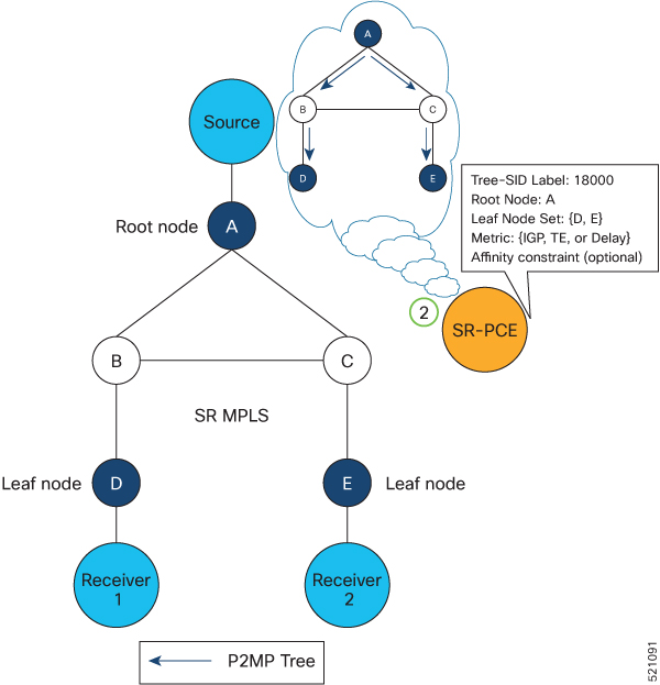
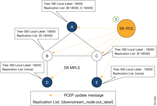
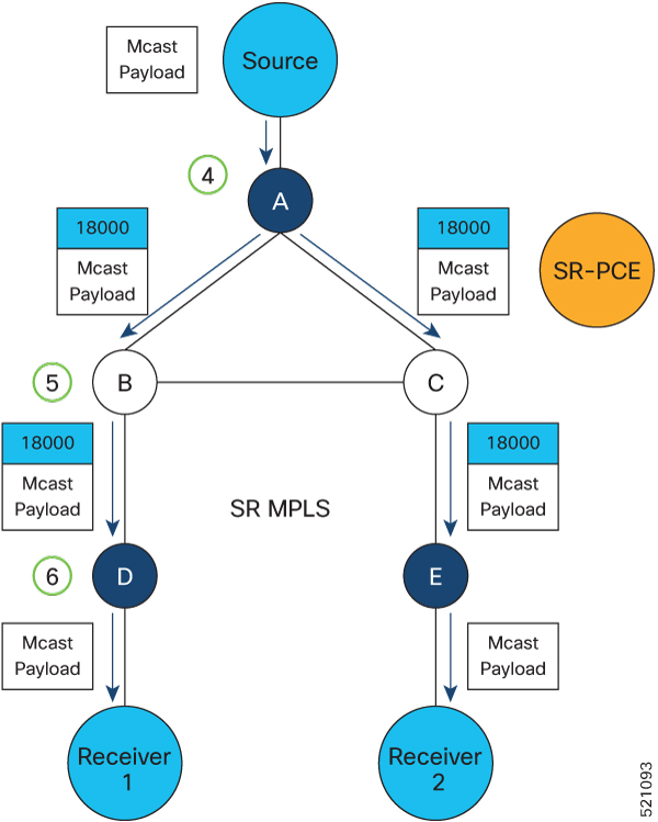
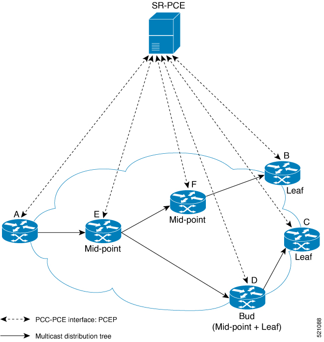
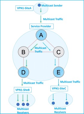
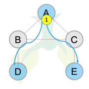
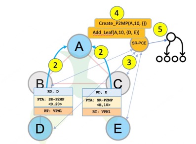
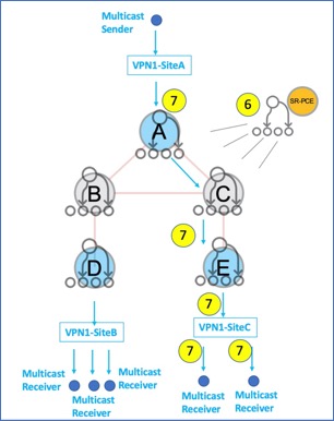
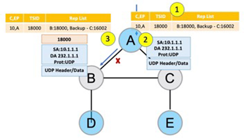
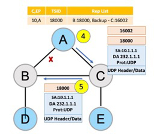
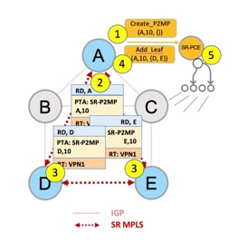
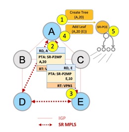
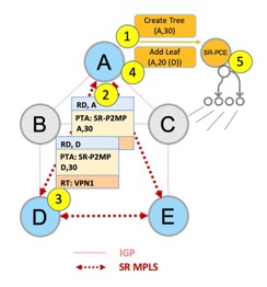
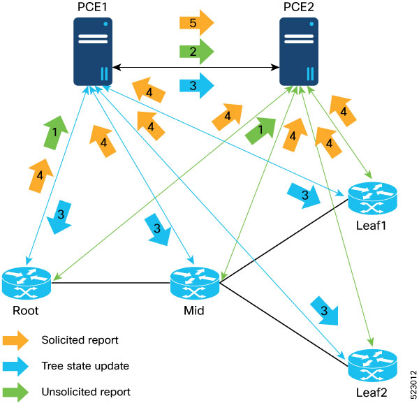
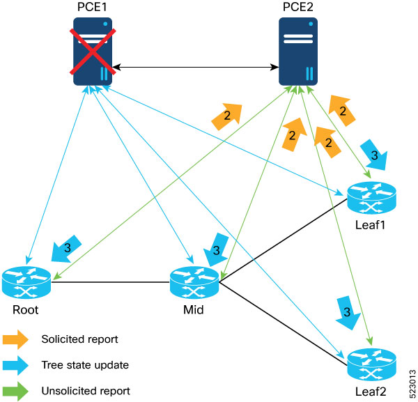
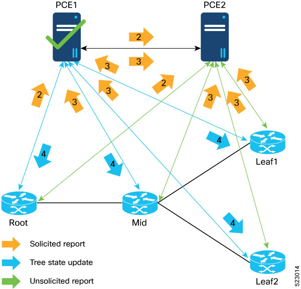
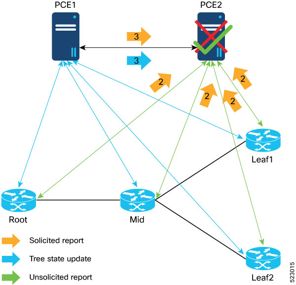

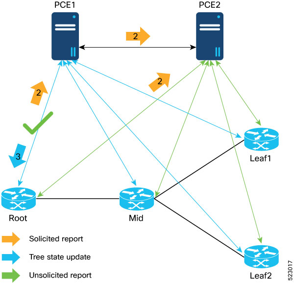
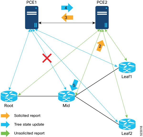
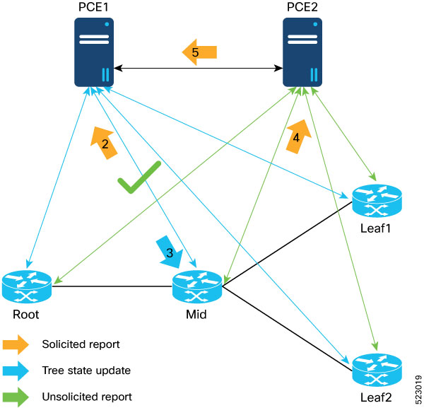
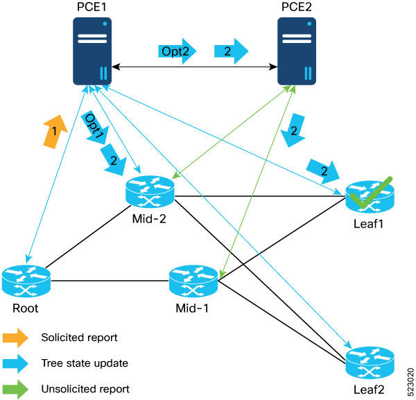
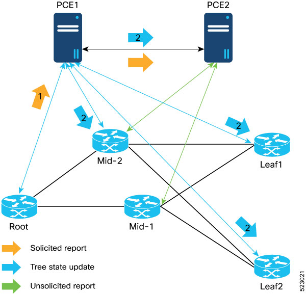
 Feedback