Configure Segment Routing Microloop Avoidance

The Segment Routing Microloop Avoidance feature enables link-state routing protocols, such as IS-IS and OSPF, to prevent or avoid microloops during network convergence after a topology change.

About Segment Routing Microloop Avoidance

IP hop-by-hop routing may induce microloops (uLoops) at any topology transition. Microloops are a day-one IP challenge. Microloops are brief packet loops that occur in the network following a topology change:

  • Link down or up (remote or local)

  • Metric increase or decrease (remote or local)

  • OSPFv2 only — Single-node cost-out: This occurs when a Router LSA (Link State Advertisement) is received with all non-stub links set to the maximum metric (link cost of 65535). It indicates that the node is being taken out of the routing path by setting the links to an unreachable state.

  • OSPFv2 only — Single-node cost-in: This occurs when a Router LSA is received that brings the node back into the routing path by changing at least one non-stub link from the maximum metric mode.

Microloops are caused by the non-simultaneous convergence of different nodes in the network. If a node converges and sends traffic to a neighbor node that has not converged yet, traffic may be looped between these two nodes, resulting in packet loss, jitter, and out-of-order packets.

Segment Routing can be used to resolve the microloop problem. A router with the Segment Routing Microloop Avoidance feature detects if microloops are possible for a destination on the post-convergence path following a topology change associated with a remote link event.

If a node determines that a microloop could occur on the new topology, the IGP computes a microloop-avoidant path by updating the forwarding table and temporarily (based on a RIB update delay timer) installing the SID-list imposition entries associated with the microloop-avoidant path for the destination. Traffic is steered to that destination loop-free.

After the RIB update delay timer expires, IGP updates the forwarding table and removes the microloop-avoidant SID list. Traffic now natively follows the post-convergence path.

SR microloop avoidance is a local behavior and therefore not all nodes need to implement it to get the benefits.

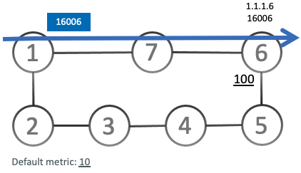
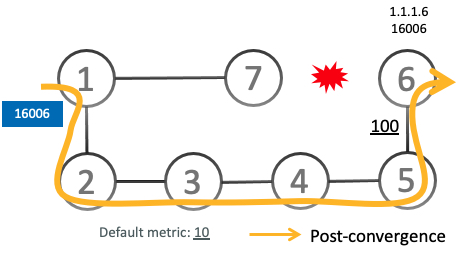
In the topology below, microloops can occur after the failure of the link between Node6 and Node7, or if Node6 costs out.

At steady state, Node1 sends traffic to node 6 (16006) via Node7. Node 7 is configured with TI-LFA to protect traffic to Node6.

TI-LFA on Node7 pre-computes a backup path for traffic to Node6 (prefix SID 16006) that will be activated if the link between Node7 and Node6 goes down. In this network, the backup path would steer traffic toward Node5 (prefix SID 16005) and then via link between Node5 and Node6 (adj-SID 24056). All nodes are notified of the topology change due to the link failure.

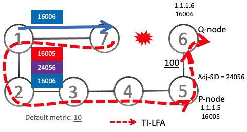
However, if nodes along the path do not converge at the same time, microloops can be introduced. For example, if Node2 converged before Node3, Node3 would send traffic back to Node2 as the shortest IGP path to Node6. The traffic between Node2 and Node3 creates a microloop.

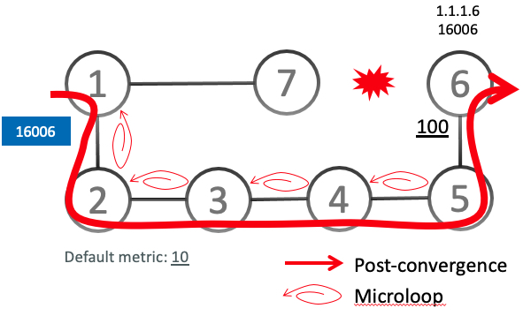
With microloop avoidance configured on Node1, a post-convergence path is computed and possible microloops on the post-convergence path for any destination are detected.

If microloops are possible on the post-convergence path to Node6, a microloop-avoidant path is constructed to steer the traffic to Node6 loop-free over the microloop-avoidant path {16005, 24056, 16006}.

Node1 updates the forwarding table and installs the SID-list imposition entries for those destinations with possible microloops, such as Node6. All nodes converge and update their forwarding tables, using SID lists where needed.

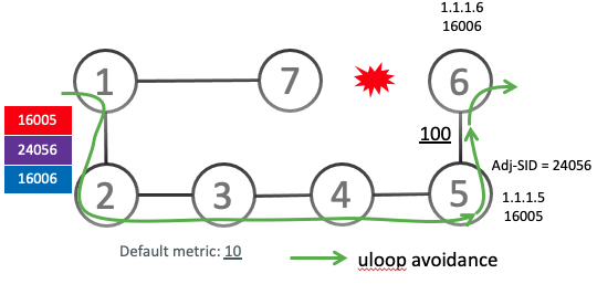
After the RIB update delay timer expires, the microloop-avoidant path is replaced with regular forwarding paths; traffic now natively follows the post-convergence path.

Usage Guidelines and Limitations

IGP directly programs a microloop-avoidant path requiring 3 or fewer labels, including the label of the destination prefix.

The platform does not support programming of microloop-avoidant paths requiring more than 3 labels.

Configure Segment Routing Microloop Avoidance for IS-IS

This task describes how to enable Segment Routing Microloop Avoidance and set the Routing Information Base (RIB) update delay value for IS-IS.

Before you begin

Ensure that the following topology requirements are met:

Procedure

  Command or Action Purpose

Step 1

configure

Example:


RP/0/RP0/CPU0:router# configure

Enters global configuration mode.

Step 2

router isis instance-id

Example:


RP/0/RP0/CPU0:router(config)# router isis 1

Enables IS-IS routing for the specified routing instance, and places the router in router configuration mode.

You can change the level of routing to be performed by a particular routing instance by using the is-type router configuration command.

Step 3

address-family ipv4 [ unicast ]

Example:


RP/0/RP0/CPU0:router(config-isis)# address-family ipv4 unicast 

Specifies the IPv4 address family and enters router address family configuration mode.

Step 4

microloop avoidance segment-routing

Example:


RP/0/RP0/CPU0:router(config-isis-af)# microloop avoidance segment-routing 

Enables Segment Routing Microloop Avoidance.

Step 5

microloop avoidance rib-update-delay delay-time

Example:


RP/0/RP0/CPU0:router(config-isis-af)# microloop avoidance rib-update-delay 3000 

Specifies the amount of time the node uses the microloop avoidance policy before updating its forwarding table. The delay-time is in milliseconds. The range is from 1-60000. The default value is 5000.

Microloop Avoidance for IS-IS with Per-Prefix Filtering

Table 1. Feature History Table

Feature Name

Release Information

Feature Description

Microloop Avoidance for IS-IS with Per-Prefix Filtering

Release 7.11.1

Introduced in this release on: NCS 5500 fixed port routers; NCS 5700 fixed port routers; NCS 5500 modular routers (NCS 5500 line cards; NCS 5700 line cards [Mode: Compatibility; Native])

Currently, when SR Microloop Avoidance for IS-IS is enabled, it applies to all prefixes.

This feature allows you to selectively allow or deny specific IPv4 or IPv6 prefixes or routes that may cause microloops, which allows for efficient use of hardware resources and ensures overall network stability.

This feature introduces these changes:

CLI:

YANG Data Model:

Per-prefix filtering is an enhancement to the existing IOS XR IS-IS SR microloop avoidance feature. Per-prefix filtering allows network administrators to specify a subset of IP prefixes (v4 and v6) to which micro loop avoidance mechanisms can be applied.


Note


Per-prefix filtering is available only for SR microloop avoidance and is not supported for local microloop avoidance.

When SR microloop avoidance is enabled, it applies to all prefixes. However, it might be important to preserve hardware resources for certain prefixes. In such a cases, it is beneficial to use SR microloop avoidance per-prefix filtering to allow only those prefixes without such limitations to be subjected to SR microloop avoidance. Per-prefix filtering provides a level of granularity that allows you to apply microloop avoidance only for the prefixes that require it, and to avoid consumption of resources that might otherwise be exhausted.

SR Microloop avoidance per-prefix filtering is configured under the IPv4 or IPv6 address family (AF). It will only be used for filtering in that specific AF. Filtering is applied to prefixes from all algorithms (Algo 0, Flexible Algorithms 128 to 255).

  • For SR MLPS – If a prefix has multiple Flexible Algorithm paths and the filtering configuration permits SR microloop avoidance for that prefix, then SR microloop avoidance is allowed for "all" Flexible Algorithm paths associated with that prefix. On the other hand, if a prefix has multiple Flexible Algorithm paths and the filtering configuration prohibits SR microloop avoidance for that prefix, then microloop avoidance is disabled for all Flexible Algorithm paths associated with that prefix.

  • For SRv6 – Regardless of the association of the prefix to the algorithm, filtering is applied solely on a per-prefix basis.

SR microloop avoidance per-prefix filtering uses route policies to identify the prefixes subjected to microloop avoidance. When SR microloop avoidance per-prefix filtering is enabled, the prefixes are verified against the route policy as follows:

  • If the route policy permits the prefixes (pass), SR microloop avoidance computes the explicit path for the prefixes.

  • If the route policy prevents the prefixes from being considered for SR microloop avoidance (drop), it is treated as if there is no explicit path defined for that prefix. The network will rely on the standard routing mechanisms to determine the path for those prefixes after convergence.

Usage Guidelines and Limitations

  • SR microloop avoidance per-prefix filtering is supported only for IS-IS.

  • A route policy must be defined before it can be attached to the SR microloop avoidance configuration.

  • Inline modification of a route policy is not supported. Once a route policy is defined and attached to the SR microloop avoidance configuration, it cannot be modified or removed until the route policy is removed from the SR microloop avoidance configuration.

  • The following match types are supported for route policies used for SR microloop avoidance per-prefix filtering:

Example: Configuration

  1. Identify the prefixes to be filtered by defining a prefix set or applying a tags to prefixes.

    • Prefix Set

      prefix-set pset-sample-ipv4
        2.3.3.3/32,
        2.4.4.4/32
        2.5.5.5/32
      end-set
      
      prefix-set pset-sample-ipv6
        2001:0:0:1::/64,
        2001:0:0:2::/64,
        2001:0:0:2::/64,
        2001:0:0:2::/64
      end-set
      
      
    • Tag

      router isis 1
       interface Loopback1
        address-family ipv4 unicast
         tag 7
         prefix-sid index 7
      
      
  2. Create a route policy for the destinations (prefix set) or tagged prefixes.

    • Destination

      route-policy BAR
        if destination in pset-sample-ipv4 then
          pass
        else
          drop
        endif
      end-policy
      
      route-policy BAR2
        if destination in (2.3.3.3/32, 2.4.4.4/32) then
          pass
        else
          drop
        endif
      end-policy
      
      route-policy BAR3
        if destination in pset-sample-ipv6 then
          drop
        else
          pass
        endif
      end-policy
      
      
    • Tag

      route-policy FOO
        if tag eq 7 then
          drop
        endif
        pass
      end-policy
      
      route-policy FOO2
        if tag eq 7 then
          pass
        else
          drop
        endif
      end-policy
      
      
  3. Use the microloop avoidance segment-routing route-policy name command to attach the route policy to the SR Microloop Avoidance configuration.

    router isis 1
     address-family ipv4 unicast
      microloop avoidance segment-routing route-policy FOO2
      !
     ! 
     address-family ipv6 unicast
      microloop avoidance segment-routing route-policy BAR3


Verify

Use the show isis command to verify that SR microloop avoidance is enabled under the AF and the route policy is applied for per-prefix filtering.

Router# show isis

IS-IS Router: 1
  System Id: 0000.0000.0001 
    IS Levels: level-2-only
  Manual area address(es):
    49.0001
  Routing for area address(es):
    49.0001
  Multi-Instance Id: 0
  Job Id: 1013
  PID: 61171
  Respawn count: 1
  Started: Thu Feb 23 02:57:58 2023
  LSP MTU: 1400
  LSP Full: level-1: No, level-2: No
  Non-stop forwarding: Cisco Proprietary NSF Restart enabled
  Most recent startup mode: Cold Restart
  TE connection status: Up
  XTC connection status: Up
  Overload Bit: not configured
  Maximum Metric: not configured
  Topologies supported by IS-IS:
    IPv4 Unicast
      Rib connected
      Level-2
        Metric style (generate/accept): Wide/Wide
        Metric: 10
        Microloop avoidance: Enabled
          Configuration: Type: Segment Routing, RIB update delay: 60000 msec, Policy: FOO2
      No protocols redistributed
      Distance: 115
      Advertise Passive Interface Prefixes Only: No
    IPv6 Unicast
      Rib connected
      Level-2
        Metric: 10
        Microloop avoidance: Enabled
          Configuration: Type: Segment Routing, RIB update delay: 5000 msec, Policy: BAR3
      No protocols redistributed
      Distance: 115
      Advertise Passive Interface Prefixes Only: No
  SR-MPLS:
    SRLB allocated: 15000 - 15999
    SRGB allocated: 16000 - 23999
  SRv6:
    Configured locators:
      USID_ALG0 (Active)
      USID_ALG128 (Active)
  Interfaces supported by IS-IS 1:
    Loopback0 is running actively (active in configuration)
    GigabitEthernet0/2/0/0 is running actively (active in configuration)
    GigabitEthernet0/2/0/3 is running actively (active in configuration)
    GigabitEthernet0/2/0/4 is running actively (active in configuration)
    GigabitEthernet0/2/0/6 is running actively (active in configuration)
    GigabitEthernet0/2/0/7 is running actively (active in configuration)

Configure Segment Routing Microloop Avoidance for OSPF

Table 2. Feature History Table

Feature Name

Release Information

Feature Description

Microloop Avoidance for OSPFv2 Single-Node Cost-in and Single-Node Cost-out Events

Release 7.11.1

Introduced in this release on: NCS 5500 fixed port routers; NCS 5700 fixed port routers; NCS 5500 modular routers (NCS 5500 line cards; NCS 5700 line cards [Mode: Compatibility; Native])

Microloops disrupt network connectivity and cause suboptimal routing decisions. This feature avoids microloops by implementing the Greedy walk algorithm, which is similar to TI-LFA computation.

This feature extends the microloop avoidance support for additional scenarios in OSPFv2, such as cost-in and cost-out events.

This feature introduces these changes:

YANG Data Model:

This task describes how to enable Segment Routing Microloop Avoidance and set the Routing Information Base (RIB) update delay value for OSPF.

Before you begin

Ensure that the following topology requirements are met:

Procedure

  Command or Action Purpose

Step 1

configure

Example:


RP/0/RP0/CPU0:router# configure

Enters global configuration mode.

Step 2

router ospf process-name

Example:


RP/0/RP0/CPU0:router(config)# router ospf 1

Enables OSPF routing for the specified routing process, and places the router in router configuration mode.

Step 3

microloop avoidance segment-routing

Example:


RP/0/RP0/CPU0:router(config-ospf)# microloop avoidance segment-routing 

Enables Segment Routing Microloop Avoidance.

Step 4

microloop avoidance rib-update-delay delay-time

Example:


RP/0/RP0/CPU0:router(config-ospf)# microloop avoidance rib-update-delay 3000 

Specifies the amount of time the node uses the microloop avoidance path before updating its forwarding table. The delay-time is in milliseconds. The range is from 1-60000. The default value is 5000.