Configure Segment Routing over IPv6 (SRv6) with Full-Length SIDs


Note


IOS XR release 7.3.2 supports SRv6 with Full-length SID and Micro-SID formats; however, only one format is supported in the network at a time.

To use SRv6 Full-length SID, enter the hw-module profile segment-routing srv6 mode base command in config mode, then reload the router or line card. See Configuring SRv6 for more information.

To use SRv6 Micro-SID (uSID), see the Configure Segment Routing over IPv6 (SRv6) with Micro-SIDs chapter.


Segment Routing for IPv6 (SRv6) is the implementation of Segment Routing over the IPv6 dataplane.

Segment Routing over IPv6 Overview

Table 1. Feature History Table

Feature Name

Release Information

Feature Description

SRv6 Network Instructions

Release 7.5.1

This feature is now supported on Cisco NCS 5700 series fixed port routers and the Cisco NCS 5500 series routers that have the Cisco NC57 line cards installed and operating in the native mode.

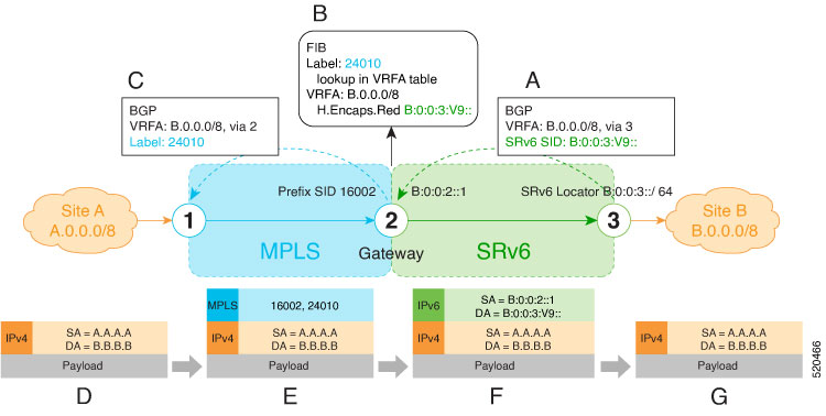
Segment Routing (SR) can be applied on both MPLS and IPv6 data planes. Segment Routing over IPv6 (SRv6) extends Segment Routing support with IPv6 data plane.

In an SR-MPLS enabled network, an MPLS label represents an instruction. The source nodes programs the path to a destination in the packet header as a stack of labels.

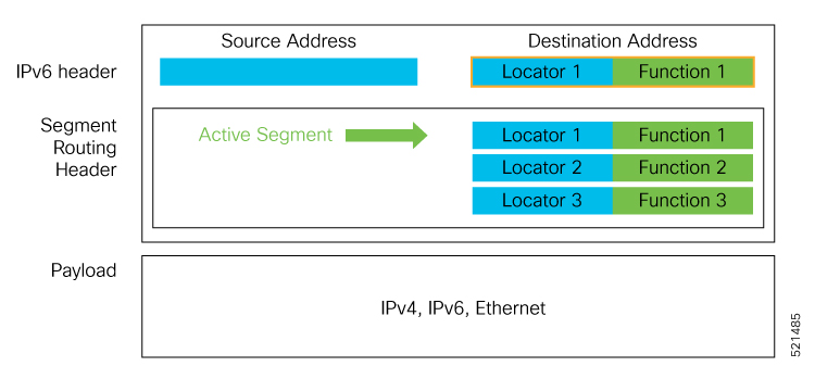
SRv6 introduces the Network Programming framework that enables a network operator or an application to specify a packet processing program by encoding a sequence of instructions in the IPv6 packet header. Each instruction is implemented on one or several nodes in the network and identified by an SRv6 Segment Identifier (SID) in the packet. The SRv6 Network Programming framework is defined in IETF RFC 8986 SRv6 Network Programming.

In SRv6, an IPv6 address represents an instruction. SRv6 uses a new type of IPv6 Routing Extension Header, called the Segment Routing Header (SRH), in order to encode an ordered list of instructions. The active segment is indicated by the destination address of the packet, and the next segment is indicated by a pointer in the SRH.

Figure 1. Network Program in the Packet Header

The SRv6 SRH is documented in IETF RFC IPv6 Segment Routing Header (SRH).

The SRH is defined as follows:


     0                   1                   2                   3
     0 1 2 3 4 5 6 7 8 9 0 1 2 3 4 5 6 7 8 9 0 1 2 3 4 5 6 7 8 9 0 1
    +-+-+-+-+-+-+-+-+-+-+-+-+-+-+-+-+-+-+-+-+-+-+-+-+-+-+-+-+-+-+-+-+
    | Next Header   |  Hdr Ext Len  | Routing Type  | Segments Left |
    +-+-+-+-+-+-+-+-+-+-+-+-+-+-+-+-+-+-+-+-+-+-+-+-+-+-+-+-+-+-+-+-+
    |  Last Entry   |     Flags     |              Tag              |
    +-+-+-+-+-+-+-+-+-+-+-+-+-+-+-+-+-+-+-+-+-+-+-+-+-+-+-+-+-+-+-+-+
    |                                                               |
    |            Segment List[0] (128-bit IPv6 address)             |
    |                                                               |
    |                                                               |
    +-+-+-+-+-+-+-+-+-+-+-+-+-+-+-+-+-+-+-+-+-+-+-+-+-+-+-+-+-+-+-+-+
    |                                                               |
    |                                                               |
                                  ...
    |                                                               |
    |                                                               |
    +-+-+-+-+-+-+-+-+-+-+-+-+-+-+-+-+-+-+-+-+-+-+-+-+-+-+-+-+-+-+-+-+
    |                                                               |
    |            Segment List[n] (128-bit IPv6 address)             |
    |                                                               |
    |                                                               |
    +-+-+-+-+-+-+-+-+-+-+-+-+-+-+-+-+-+-+-+-+-+-+-+-+-+-+-+-+-+-+-+-+
    //                                                             //
    //         Optional Type Length Value objects (variable)       //
    //                                                             //
    +-+-+-+-+-+-+-+-+-+-+-+-+-+-+-+-+-+-+-+-+-+-+-+-+-+-+-+-+-+-+-+-+

The following list explains the fields in SRH:

  • Next header—Identifies the type of header immediately following the SRH.

  • Hdr Ext Len (header extension length)—The length of the SRH in 8-octet units, not including the first 8 octets.

  • Segments left—Specifies the number of route segments remaining. That means, the number of explicitly listed intermediate nodes still to be visited before reaching the final destination.

  • Last Entry—Contains the index (zero based) of the last element of the segment list.

  • Flags— Contains 8 bits of flags.

  • Tag—Tag a packet as part of a class or group of packets like packets sharing the same set of properties.

  • Segment list—128-bit IPv6 addresses representing the nth segment in the segment list. The segment list encoding starts from the last segment of the SR policy (path). That means the first element of the segment list (Segment list [0]) contains the last segment of the SR policy, the second element contains the penultimate segment of the SR policy and so on.

In SRv6, a SID represents a 128-bit value, consisting of the following three parts:

  • Locator: This is the first part of the SID with most significant bits and represents an address of a specific SRv6 node.

  • Function: This is the portion of the SID that is local to the owner node and designates a specific SRv6 function (network instruction) that is executed locally on a particular node, specified by the locator bits.

  • Args: This field is optional and represents optional arguments to the function.

The locator part can be further divided into two parts:

  • SID Block: This field is the SRv6 network designator and is a fixed or known address space for an SRv6 domain. This is the most significant bit (MSB) portion of a locator subnet.

  • Node Id: This field is the node designator in an SRv6 network and is the least significant bit (LSB) portion of a locator subnet.

SRv6 Node Roles

Each node along the SRv6 packet path has a different functionality:

  • Source node—A node that can generate an IPv6 packet with an SRH (an SRv6 packet), or an ingress node that can impose an SRH on an IPv6 packet.

  • Transit node—A node along the path of the SRv6 packet (IPv6 packet and SRH). The transit node does not inspect the SRH. The destination address of the IPv6 packet does not correspond to the transit node.

  • Endpoint node—A node in the SRv6 domain where the SRv6 segment is terminated. The destination address of the IPv6 packet with an SRH corresponds to the end point node. The segment endpoint node executes the function bound to the SID

SRv6 Head-End Behaviors

The SR Headend with Encapsulation behaviors are documented in the IETF RFC 8986 SRv6 Network Programming.

The SR Headend with Insertion head-end behaviors are documented in the following IETF draft:

https://datatracker.ietf.org/doc/draft-filsfils-spring-srv6-net-pgm-insertion/

This section describes a set of SR Policy headend behaviors. The following list summarizes them:

  • H.Encaps—SR Headend Behavior with Encapsulation in an SRv6 Policy

  • H.Encaps.Red—H.Encaps with Reduced Encapsulation

  • H.Insert—SR Headend with insertion of an SRv6 Policy

  • H.Insert.Red—H.Insert with reduced insertion

SRv6 Endpoint Behaviors

The SRv6 endpoint behaviors are documented in the IETF RFC 8986 SRv6 Network Programming.

The following is a subset of defined SRv6 endpoint behaviors that can be associated with a SID.

  • End—Endpoint function. The SRv6 instantiation of a Prefix SID [RFC8402].

  • End.X—Endpoint with Layer-3 cross-connect. The SRv6 instantiation of an Adj SID [RFC8402].

  • End.DX6—Endpoint with decapsulation and IPv6 cross-connect (IPv6-L3VPN - equivalent to per-CE VPN label).

  • End.DX4—Endpoint with decapsulation and IPv4 cross-connect (IPv4-L3VPN - equivalent to per-CE VPN label).

  • End.DT6—Endpoint with decapsulation and IPv6 table lookup (IPv6-L3VPN - equivalent to per-VRF VPN label).

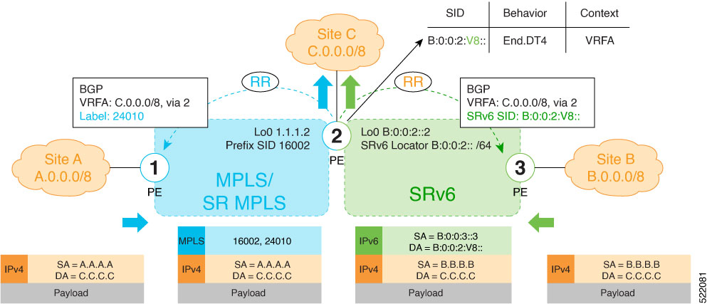
  • End.DT4—Endpoint with decapsulation and IPv4 table lookup (IPv4-L3VPN - equivalent to per-VRF VPN label).

  • End.DT46—Endpoint with decapsulation and specific IP table lookup (IP-L3VPN - equivalent to per-VRF VPN label).

  • End.DX2—Endpoint with decapsulation and L2 cross-connect (L2VPN use-case).

  • End.B6.Encaps—Endpoint bound to an SRv6 policy with encapsulation. SRv6 instantiation of a Binding SID.

  • End.B6.Encaps.RED—End.B6.Encaps with reduced SRH. SRv6 instantiation of a Binding SID.

SRv6 Endpoint Behavior Variants

Table 2. Feature History Table

Feature Name

Release Information

Feature Description

SRv6: Ultimate Segment Decapsulation (USD) on Full-length SIDs

Release 7.5.2

The Ultimate Segment Decapsulation (USD) variant is supported on SRv6 endpoint nodes using full-length SIDs. One of the USD variant applications is the case of TI-LFA in P routers with encapsulation with H.Encaps. The USD variant allows the last Segment Endpoint Node in the repair path list to decapsulate the IPv6 header added at the TI-LFA Point of Local Repair and forward the inner packet.

In earlier releases, the USD variant was supported on SRv6 endpoint nodes using Micro SIDs (uSIDs).

Depending on how the SRH is handled, different behavior variants are defined for the End and End.X behaviors. The End and End.X behaviors can support these variants, either individually or in combinations.

  • Penultimate Segment Pop (PSP) of the SRH variant—An SR Segment Endpoint Nodes receive the IPv6 packet with the Destination Address field of the IPv6 Header equal to its SID address.

    A penultimate SR Segment Endpoint Node is one that, as part of the SID processing, copies the last SID from the SRH into the IPv6 Destination Address and decrements the Segments Left value from one to zero.

    The PSP operation takes place only at a penultimate SR Segment Endpoint Node and does not happen at non-penultimate endpoint nodes. When a SID of PSP-flavor is processed at a non-penultimate SR Segment Endpoint Node, the PSP behavior is not performed since Segments Left would not be zero.

    The SR Segment Endpoint Nodes advertise the SIDs instantiated on them via control plane protocols. A PSP-flavored SID is used by the Source SR Node when it needs to instruct the penultimate SR Segment Endpoint Node listed in the SRH to remove the SRH from the IPv6 header.

  • Ultimate Segment Pop (USP) of the SRH variant—The SRH processing of the End and End.X behaviors are modified as follows:

    If Segments Left is 0, then:

    1. Update the Next Header field in the preceding header to the Next Header value of the SRH

    2. Decrease the IPv6 header Payload Length by 8*(Hdr Ext Len+1)

    3. Remove the SRH from the IPv6 extension header chain

    4. Proceed to process the next header in the packet

    One of the applications of the USP flavor is when a packet with an SRH is destined to an application on hosts with smartNICs implementing SRv6. The USP flavor is used to remove the consumed SRH from the extension header chain before sending the packet to the host.

  • Ultimate Segment Decapsulation (USD) variant—The Upper-layer header processing of the End and End.X behaviors are modified as follows:

    • End behavior: If the Upper-layer Header type is 41 (IPv6), then:

      1. Remove the outer IPv6 Header with all its extension headers

      2. Submit the packet to the egress IPv6 FIB lookup and transmission to the new destination

      3. Else, if the Upper-layer Header type is 4 (IPv4)

      4. Remove the outer IPv6 Header with all its extension headers

      5. Submit the packet to the egress IPv4 FIB lookup and transmission to the new destination

      6. Else, process as per Section 4.1.1 (Upper-Layer Header) of IETF RFC 8986 SRv6 Network Programming

    • End.X behavior: If the Upper-layer Header type is 41 (IPv6) or 4 (IPv4), then:

      1. Remove the outer IPv6 Header with all its extension headers

      2. Forward the exposed IP packet to the L3 adjacency J

      3. Else, process as per Section 4.1.1 (Upper-Layer Header) of IETF RFC 8986 SRv6 Network Programming

    One of the applications of the USD flavor is the case of TI-LFA in P routers with encapsulation with H.Encaps. The USD flavor allows the last Segment Endpoint Node in the repair path list to decapsulate the IPv6 header added at the TI-LFA Point of Local Repair and forward the inner packet.

Usage Guidelines and Limitations

General Guidelines and Limitations

  • Cisco IOS XR Release 7.5.2 and later supports the following SRv6 SID behaviors and variants:

    • END with PSP/USD

    • END.X with PSP/USD

    • END.DT4

    • END.DT6

  • SRv6 Underlay support includes:

    • IGP redistribution/leaking between levels

    • Prefix Summarization on ABR routers

    • IS-IS TI-LFA

    • Microloop Avoidance

    • Flex-algo

Configuring SRv6

To enable SRv6 globally, you should first configure a locator with its prefix. The IS-IS protocol announces the locator prefix in IPv6 network and SRv6 applications (like ISIS, BGP) use it to allocate SIDs.

The following usage guidelines and restrictions apply while configuring SRv6.

  • All routers in the SRv6 domain should have the same SID block (network designator) in their locator.

  • The locator length should be 64-bits long.

    • The SID block portion (MSBs) cannot exceed 40 bits. If this value is less than 40 bits, user should use a pattern of zeros as a filler.

    • The Node Id portion (LSBs) cannot exceed 24 bits.

  • You can configure up to 8 locators to support SRv6 Flexible Algorithm. All locators prefix must share the same SID block (first 40-bits).

Enabling SRv6 on the Platform

Before configuring SRv6 on Cisco NCS 5500 Series Routers, you must first use the following command in config mode:

  • hw-module profile segment-routing srv6 mode base

    You must reload the router after enabling this command.


    Note


    Starting from Release 7.10.1, the SRv6 mode is automatically set to base-and-micro-segment-f3216 mode (dual mode) even if you configure the base mode. The running configuration would still continue to reflect the user configured mode only.

    You can verify the change using the following console log:
    fia_driver[238]: %FABRIC-FIA_DRVR-6-HW_MOD_PROFILE_AUTO_CONVERTED : 
    Auto-converting SRv6 hw-module base profile to base-and-micro-segment-f3216 profile

Enabling SRv6 with Locator

This example shows how to globally enable SRv6 and configure locator.

Router(config)# segment-routing srv6
Router(config-srv6)# locators
Router(config-srv6-locators)# locator myLoc1
Router(config-srv6-locator)# prefix 2001:db8:0:a2::/64
(Optional) Configuring SRv6 Anycast Locator

An SRv6 Anycast locator is a type of locator that identifies a set of nodes (END SIDs). SRv6 Anycast Locators and their associated END SIDs may be provisioned at multiple places in a topology.

The set of nodes (Anycast group) is configured to advertise a shared Anycast locator and END SID. Anycast routing enables the steering of traffic toward multiple advertising nodes. Packets addressed to an Anycast address are forwarded to the topologically nearest nodes.

One use case is to advertise Anycast END SIDs at exit points from an SRv6 network. Any of the nodes that advertise the common END SID could be used to forward traffic out of the SRv6 portion of the network to the topologically nearest node.

Unlike a normal locator, IS-IS does not program or advertise END.X SIDs associated with an anycast locator.


Note


END SIDs allocated from Anycast locators will not be used in constructing TI-LFA backup paths or Microloop Avoidance primary paths. TI-LFA backup and Microloop Avoidance paths for an Anycast locator prefix may terminate on any node advertising that locator, which may be different from the node terminating the original primary path.

Note


SRv6 anycast locators may have non-zero algorithm (Flexible Algorithm) values.

The following example shows how to globally enable SRv6 and configure Anycast locator.


Note


For Cisco NCS 5500 Series Routers, you must first use the hw-module profile segment-routing srv6 command to enable SRv6 functionality. Then, reload the line card after enabling this command.
Router(config)# hw-module profile segment-routing srv6
Router(config)# segment-routing srv6
Router(config-srv6)# locators
Router(config-srv6-locators)# locator myLoc1 anycast
Router(config-srv6-locator)# prefix 2001:db8:0:a2::/64
Optional: Configuring Encapsulation Parameters

This example shows how to configure encapsulation parameters when configuring SRv6. These optional parameters include:

  • segment-routing srv6 encapsulation source-address ipv6-addr—Source Address of outer encapsulating IPv6 header. The default source address for encapsulation is one of the loopback addresses.

  • segment-routing srv6 encapsulation hop-limit {count | propagate}—The hop limit of outer-encapsulating IPv6 header. The range for count is from 1 to 254 for NCS 5500 and from 1 to 255 for NCS 5700; the default value for hop-limit is 254. Use propagate to set the hop-limit value by propagation (from incoming packet/frame).


    Note


    On NCS 5700 hardware, hop-limit propagation is not applied for packets going to ELINE (P2P) services.


Router(config)# segment-routing srv6
Router(config-srv6)# encapsulation source-address 1::1
Router(config-srv6)# hop-limit 60

Optional: Enabling Syslog Logging for Locator Status Changes

This example shows how to enable the logging of locator status.

Router(config)# segment-routing srv6
Router(config-srv6)# logging locator status

Verifying SRv6 Manager

This example shows how to verify the overall SRv6 state from SRv6 Manager point of view. The output displays parameters in use, summary information, and platform specific capabilities.


Router# show segment-routing srv6 manager 
Parameters:
  Parameters:
  SRv6 Enabled: Yes
  SRv6 Operational Mode:
    Base:
      SID Base Block: 2001:db8::/40
  Encapsulation:
    Source Address:
      Configured: 1::1
      Default: 5::5
    Hop-Limit: Default 
    Traffic-class: Default
Summary:
  Number of Locators: 1 (1 operational)
  Number of SIDs: 4 (0 stale)
  Max SIDs: 64000
  OOR:
    Thresholds: Green 3200, Warning 1920
    Status: Resource Available
        History: (0 cleared, 0 warnings, 0 full)
    Block 2001:db8:0:a2::/64:
        Number of SIDs free: 65470
        Max SIDs: 65470
        Thresholds: Green 3274, Warning 1965
        Status: Resource Available
            History: (0 cleared, 0 warnings, 0 full)
Platform Capabilities:
  SRv6: Yes
  TILFA: Yes
  Microloop-Avoidance: Yes
  Endpoint behaviors:
    End (PSP)
    End.X (PSP)
    End.DX6
    End.DX4
    End.DT6
    End.DT4
    End.DX2
    uN (PSP/USD)
    uA (PSP/USD)
    uDT6
    uDT4
    uDX2
    uB6 (Insert.Red)
  Headend behaviors:
    T
    H.Insert.Red
    H.Encaps.Red
  Security rules:
    SEC-1
    SEC-2
    SEC-3
  Counters:
    CNT-1
    CNT-3
  Signaled parameters:
    Max-SL          : 3
    Max-End-Pop-SRH : 3
    Max-H-Insert    : 3 sids
    Max-H-Encap     : 3 sids
    Max-End-D       : 4
  Configurable parameters (under srv6):
    Encapsulation:
      Source Address: Yes
      Hop-Limit     : value=Yes, propagate=No
      Traffic-class : value=Yes, propagate=Yes
  Max SIDs: 64000
  SID Holdtime: 3 mins

Verifying SRv6 Locator

This example shows how to verify the locator configuration and its operational status.


Router# show segment-routing srv6 locator myLoc1 detail 
Name                 ID      Prefix                   Status
-------------------- ------- ------------------------ -------
myLoc1*              5       2001:db8:0:a2::/64       Up
  (*): is-default
  Interface:
    Name: srv6-myLoc1 
    IFH : 0x00000170
    IPv6 address: 2001:db8:0:a2::/64 
  Chkpt Obj ID: 0x2fc8
  Created: Apr 25 06:21:57.077 (00:03:37 ago)

Verifying SRv6 Local SIDs

This example shows how to verify the allocation of SRv6 local SIDs off locator(s).


Router# show segment-routing srv6 locator myLoc1 sid

SID                         Function     Context                           Owner               State  RW
--------------------------  -----------  ------------------------------    ------------------  -----  --
2001:db8:0:a2:1::           End (PSP)    'default':1                       sidmgr              InUse  Y
2001:db8:0:a2:40::          End.DT4      'VRF1'                            bgp-100             InUse  Y
2001:db8:0:a2:41::          End.X (PSP)  [Hu0/1/0/1, Link-Local]           isis-srv6           InUse  Y

The following example shows how to display detail information regarding an allocated SRv6 local SID.


Router# show segment-routing srv6 locator myLoc1 sid 2001:db8:0:a2:40:: detail

SID                         Function     Context                           Owner               State  RW
--------------------------  -----------  ------------------------------    ------------------  -----  --
2001:db8:0:a2:40::          End.DT4      'VRF1'                            bgp-100             InUse  Y
  SID context: { table-id=0xe0000011 ('VRF1':IPv4/Unicast) }
  Locator: myLoc1'
  Allocation type: Dynamic
  Created: Feb  1 14:04:02.901 (3d00h ago)

Similarly, you can display SID information across locators by using the show segment-routing sid command.

show Commands

You can use the following show commands to verify the SRv6 global and locator configuration:

Command

Description

show segment-routing srv6 manager

Displays the summary information from SRv6 manager, including platform capabilities.

show segment-routing srv6 locator locator-name [detail]

Displays the SRv6 locator information on the router.

show segment-routing srv6 locator locator-name sid [[sid-ipv6-address [detail]

Displays the information regarding SRv6 local SID(s) allocated from a given locator.

show segment-routing srv6 sid [sid-ipv6-address | all | stale] [detail]

Displays SID information across locators. By default, only “active” (i.e. non-stale) SIDs are displayed.

show route ipv6 local-srv6

Displays all SRv6 local-SID prefixes in IPv6 RIB.

Configuring SRv6 under IS-IS

Table 3. Feature History Table

Feature Name

Release Information

Feature Description

SRv6 under IS-IS

Release 7.5.1

This feature is now supported on Cisco NCS 5700 series fixed port routers and the Cisco NCS 5500 series routers that have the Cisco NC57 line cards installed and operating in the native mode.

Intermediate System-to-Intermediate System (IS-IS) protocol already supports segment routing with MPLS dataplane (SR-MPLS). This feature enables extensions in IS-IS to support Segment Routing with IPv6 data plane (SRv6). The extensions include advertising the SRv6 capabilities of nodes and node and adjacency segments as SRv6 SIDs.

SRv6 IS-IS performs the following functionalities:

  1. Interacts with SID Manager to learn local locator prefixes and announces the locator prefixes in the IGP domain.

  2. Learns remote locator prefixes from other IS-IS neighbor routers and installs the learned remote locator IPv6 prefix in RIB or FIB.

  3. Allocate or learn prefix SID and adjacency SIDs, create local SID entries, and advertise them in the IGP domain.

Usage Guidelines and Restrictions

The following usage guidelines and restrictions apply for SRv6 IS-IS:

  • An IS-IS address-family can support either SR-MPLS or SRv6, but both at the same time is not supported.

Configuring SRv6 under IS-IS

To configure SRv6 IS-IS, use the following command:

  • router isis instance address-family ipv6 unicast segment-routing srv6 locator locator [level {1 | 2}]—Enable SRv6 under the IS-IS IPv6 address-family and assign SRv6 locator(s) to it. Use the level {1 | 2} keywords to advertise the locator only in the specified IS-IS level.

The following example shows how to configure SRv6 under IS-IS.


Router(config)# router isis core
Router(config-isis)# address-family ipv6 unicast
Router(config-isis-af)# segment-routing srv6
Router(config-isis-srv6)# locator myLoc1 level 1
Router(config-isis-srv6-loc)# exit

For more information about configuring IS-IS, refer to the "Implementing IS-IS" chapter in the Routing Configuration Guide for Cisco NCS 5500.

Configuring SRv6 IS-IS Flexible Algorithm

Table 4. Feature History Table

Feature Name

Release Information

Feature Description

SRv6 IS-IS Flexible Algorithm

Release 7.5.1

This feature is now supported on Cisco NCS 5700 series fixed port routers and the Cisco NCS 5500 series routers that have the Cisco NC57 line cards installed and operating in the native mode.

This feature introduces support for implementing Flexible Algorithm using IS-IS SRv6.

SRv6 Flexible Algorithm allows operators to customize IGP shortest path computation according to their own needs. An operator can assign custom SRv6 locators to realize forwarding beyond link-cost-based SPF. As a result, Flexible Algorithm provides a traffic engineered path automatically computed by the IGP to any destination reachable by the IGP.

Restrictions and Usage Guidelines

The following restrictions and usage guidelines apply:

  • You can configure up to 8 locators to support SRv6 Flexible Algorithm:

    • All locators prefix must share the same SID block (first 40-bits).

    • The Locator Algorithm value range is 128 to 255.

Configuring SRv6 IS-IS Flexible Algorithm

The following example shows how to configure SRv6 IS-IS Flexible Algorithm.


Note


Complete the SRv6 base configuration before performing these steps.

Note


For Cisco NCS5500 Series Routers, you must first use the hw-module profile segment-routing srv6 command to enable SRv6 functionality. Then, reload the line card after enabling this command.
Router(config)# hw-module profile segment-routing srv6

Router(config)# segment-routing srv6
Router(config-srv6)# locators
Router(config-srv6-locators)# locator Loc1-BE // best-effort 
Router(config-srv6-locator)# prefix 2001:db8:0:a2::/64
Router(config-srv6-locator)# exit
Router(config-srv6-locators)# locator Loc1-LL // low latency
Router(config-srv6-locator)# prefix 2001:db8:1:a2::/64
Router(config-srv6-locator)# algorithm 128
Router(config-srv6-locator)# exit
Router(config-srv6)# exit

Configuring SRv6 IS-IS

The following example shows how to configure SRv6 IS-IS.


Router(config)# router isis test-igp
Router(config-isis)# flex-algo 128
Router(config-isis-flex-algo)# exit
Router(config-isis)# address-family ipv6 unicast
Router(config-isis-af)# summary-prefix 2001:db8:0::/48 
Router(config-isis-af)# summary-prefix 2001:db8:1::/48 algorithm 128 explicit
Router(config-isis-af)# segment-routing srv6
Router(config-isis-srv6)# locator Loc1-BE
Router(config-isis-srv6-loc)# exit
Router(config-isis-srv6)# locator Loc1-LL
Router(config-isis-srv6-loc)# exit

Configuring SRv6 IS-IS Prefix Summarization

SRv6 leverages longest-prefix-match IP forwarding. Massive-scale reachability can be achieved by summarizing locators at ABRs and ASBRs. Use the summary-prefix locator [algorithm algo] [explicit] command in IS-IS address-family configuration mode to specify that only locators from the specified algorithm contribute to the summary. The explicit keyword limits the contributing prefixes to only those belonging to the same algorithm.

The following example shows how to configure SRv6 IS-IS Algorithm Summarization for regular algorithm and Flexible Algorithm (128).


Router(config)# router isis test-igp
Router(config-isis)# flex-algo 128
Router(config-isis-flex-algo)# exit
Router(config-isis)# address-family ipv6 unicast
Router(config-isis-af)# summary-prefix 2001:db8:0::/48 
Router(config-isis-af)# summary-prefix 2001:db8:1::/48 algorithm 128 explicit
Router(config-isis-af)# segment-routing srv6
Router(config-isis-srv6)# locator Loc1-BE
Router(config-isis-srv6-loc)# exit
Router(config-isis-srv6)# locator Loc1-LL
Router(config-isis-srv6-loc)# exit

Enable Flexible Algorithm for Low Latency

The following example shows how to enable Flexible Algorithm for low-latency:

  • IS-IS: Configure Flexible Algorithm definition with delay objective

  • Performance-measurement: Configure static delay per interface


Router(config)# router isis test-igp
Router(config-isis)# flex-algo 128
Router(config-isis-flex-algo)# metric-type delay 
Router(config-isis-flex-algo)# exit
Router(config-isis)# interface GigabitEthernet0/0/0/0
Router(config-isis-if)# address-family ipv6 unicast 
Router(config-isis-if-af)# root

Router(config)# performance-measurement 
Router(config-perf-meas)# interface GigabitEthernet0/0/0/0
Router(config-pm-intf)# delay-measurement
Router(config-pm-intf-dm)# advertise-delay 100
Router(config-pm-intf-dm)# commit

Verification

SRv6-LF1# show segment-routing srv6 locator 
Mon Aug 12 20:54:15.414 EDT
Name                  ID       Algo  Prefix                    Status 
--------------------  -------  ----  ------------------------  -------
Loc1-BE               17       0     2001:db8:0:a2::/64        Up     
Loc1-LL               18       128   2001:db8:1:a2::/64        Up


SRv6-LF1# show isis flex-algo 128 
Mon Aug 12 21:00:54.282 EDT

IS-IS test-igp Flex-Algo Database
  
Flex-Algo 128:

Level-2:
        Definition Priority: 128
        Definition Source: SRv6-LF1.00, (Local)
        Definition Equal to Local: Yes
        Disabled: No


Level-1:
        Definition Priority: 128
        Definition Source: SRv6-LF1.00, (Local)
        Definition Equal to Local: Yes
        Disabled: No


    Local Priority: 128
    FRR Disabled: No
    Microloop Avoidance Disabled: No

Configuring SRv6 IS-IS TI-LFA

Table 5. Feature History Table

Feature Name

Release Information

Feature Description

SRv6 IS-IS TI-LFA

Release 7.5.1

This feature is now supported on Cisco NCS 5700 series fixed port routers and the Cisco NCS 5500 series routers that have the Cisco NC57 line cards installed and operating in the native mode.

This feature introduces support for implementing Topology-Independent Loop-Free Alternate (TI-LFA) using IS-IS SRv6.

TI-LFA provides link protection in topologies where other fast reroute techniques cannot provide protection. The goal of TI-LFA is to reduce the packet loss that results while routers converge after a topology change due to a link failure. TI-LFA leverages the post-convergence path which is planned to carry the traffic and ensures link and node protection within 50 milliseconds. TI-LFA with IS-IS SR-MPLS is already supported.

TI-LFA provides link, node, and Shared Risk Link Groups (SRLG) protection in any topology.

Usage Guidelines and Restrictions

The following usage guidelines and restrictions apply:

  • TI-LFA provides link protection by default. Additional tiebreaker configuration is required to enable node or SRLG protection.

  • Usage guidelines for node and SRLG protection:

    • TI-LFA node protection functionality provides protection from node failures. The neighbor node is excluded during the post convergence backup path calculation.

    • Shared Risk Link Groups (SRLG) refer to situations in which links in a network share a common fiber (or a common physical attribute). These links have a shared risk: when one link fails, other links in the group might also fail. TI-LFA SRLG protection attempts to find the post-convergence backup path that excludes the SRLG of the protected link. All local links that share any SRLG with the protecting link are excluded.

    • When you enable link protection, you can also enable node protection, SRLG protection, or both, and specify a tiebreaker priority in case there are multiple LFAs.

    • Valid priority values are from 1 to 255. The lower the priority value, the higher the priority of the rule. Link protection always has a lower priority than node or SRLG protection.

Configuring SRv6 IS-IS TI-LFA

The following example shows how to configure SRv6 IS-IS TI-LFA.


Note


Complete the SRv6 configuration before performing these steps.

Router(config)# router isis core
Router(config-isis)# address-family ipv6 unicast
Router(config-isis-af)# segment-routing srv6
Router(config-isis-srv6)# locator locator1
Router(config-isis-srv6-loc)# exit
Router(config-isis)# interface loopback 0
Router(config-isis-if)# passive
Router(config-isis-if)# address-family ipv6 unicast 
Router(config-isis-if-af)# exit
Router(config-isis)# interface bundle-ether 1201 
Router(config-isis-if)# address-family ipv6 unicast 
Router(config-isis-if-af)# fast-reroute per-prefix  
Router(config-isis-if-af)# fast-reroute per-prefix ti-lfa
Router(config-isis-if-af)# exit
Router(config-isis)# interface bundle-ether 1301       
Router(config-isis-if)# address-family ipv6 unicast 
Router(config-isis-if-af)# fast-reroute per-prefix  
Router(config-isis-if-af)# fast-reroute per-prefix ti-lfa
Router(config-isis-if-af)# fast-reroute per-prefix tiebreaker node-protecting index 100
Router(config-isis-if-af)# fast-reroute per-prefix tiebreaker srlg-disjoint index 200
Router(config-isis-if-af)# exit

Configuring SRv6 IS-IS TI-LFA with Flexible Algorithm

TI-LFA backup paths for particular Flexible Algorithm are computed using the same constraints as the calculation of the primary paths for such Flexible Algorithm. These paths use Prefix-SIDs advertised specifically for such Flexible Algorithm in order to enforce a backup path.

The following example shows how to configure SRv6 IS-IS TI-LFA with Flexible Algorithm.


Router(config)# router isis core
Router(config-isis)# flex-algo 128
Router(config-isis-flex-algo)# exit
Router(config-isis)# address-family ipv6 unicast
Router(config-isis-af)# segment-routing srv6
Router(config-isis-srv6)# locator locator1
Router(config-isis-srv6-loc)# exit
Router(config-isis)# interface bundle-ether 1201
Router(config-isis-if)# address-family ipv6 unicast
Router(config-isis-if-af)# fast-reroute per-prefix
Router(config-isis-if-af)# fast-reroute per-prefix ti-lfa
Router(config-isis-if-af)# exit

Use the fast-reroute disable command to disable the LFA calculation on a per-algorithm basis:

Router(config)# router isis core
Router(config-isis)# flex-algo 128
Router(config-isis-flex-algo)# fast-reroute disable

Verification

This example shows how to verify the SRv6 IS-IS TI-LFA configuration using the show isis ipv6 fast-reroute ipv6-prefix detail command.


Router# show isis ipv6 fast-reroute cafe:0:0:66::/64 detail 
Thu Nov 22 16:12:51.983 EST

L1 cafe:0:0:66::/64 [11/115] low priority
     via fe80::2, TenGigE0/0/0/6, SRv6-HUB6, Weight: 0
       Backup path: TI-LFA (link), via fe80::1, Bundle-Ether1201 SRv6-LF1, Weight: 0, Metric: 51
         P node: SRv6-TP8.00 [8::8], SRv6 SID: cafe:0:0:88:1:: End (PSP)
         Backup-src: SRv6-HUB6.00
       P: No, TM: 51, LC: No, NP: No, D: No, SRLG: Yes
     src SRv6-HUB6.00-00, 6::6

This example shows how to verify the SRv6 IS-IS TI-LFA configuration using the show route ipv6 ipv6-prefix detail command.


Router# show route ipv6 cafe:0:0:66::/64 detail  
Thu Nov 22 16:14:07.385 EST

Routing entry for cafe:0:0:66::/64
  Known via "isis srv6", distance 115, metric 11, type level-1
  Installed Nov 22 09:24:05.160 for 06:50:02
  Routing Descriptor Blocks
    fe80::2, from 6::6, via TenGigE0/0/0/6, Protected
      Route metric is 11
      Label: None
      Tunnel ID: None
      Binding Label: None
      Extended communities count: 0
      Path id:1       Path ref count:0
      NHID:0x2000a(Ref:11)
      NHID eid:0xffffffffffffffff
      SRv6 Headend: H.Insert.Red [base], SRv6 SID-list {cafe:0:0:88:1::}
      Backup path id:65
    fe80::1, from 6::6, via Bundle-Ether1201, Backup (TI-LFA)
      Repair Node(s): 8::8
      Route metric is 51
      Label: None
      Tunnel ID: None
      Binding Label: None
      Extended communities count: 0
      Path id:65              Path ref count:1
      NHID:0x2000d(Ref:11)
      NHID eid:0xffffffffffffffff
      SRv6 Headend: H.Insert.Red [base], SRv6 SID-list {cafe:0:0:88:1::}
      MPLS eid:0x1380800000001

This example shows how to verify the SRv6 IS-IS TI-LFA configuration using the show cef ipv6 ipv6-prefix detail location location command.


Router# show cef  ipv6 cafe:0:0:66::/64 detail location 0/0/cpu0 
Thu Nov 22 17:01:58.536 EST
cafe:0:0:66::/64, version 1356, SRv6 Transit, internal 0x1000001 0x2 (ptr 0x8a4a45cc) [1], 0x0 (0x8a46ae20), 0x0 (0x8c8f31b0)
 Updated Nov 22 09:24:05.166 
 local adjacency fe80::2
 Prefix Len 64, traffic index 0, precedence n/a, priority 2
  gateway array (0x8a2dfaf0) reference count 4, flags 0x500000, source rib (7), 0 backups
                [5 type 3 flags 0x8401 (0x8a395d58) ext 0x0 (0x0)]
  LW-LDI[type=3, refc=1, ptr=0x8a46ae20, sh-ldi=0x8a395d58]
  gateway array update type-time 1 Nov 22 09:24:05.163
 LDI Update time Nov 22 09:24:05.163
 LW-LDI-TS Nov 22 09:24:05.166
   via fe80::2/128, TenGigE0/0/0/6, 8 dependencies, weight 0, class 0, protected [flags 0x400]
    path-idx 0 bkup-idx 1 NHID 0x2000a [0x8a2c2fd0 0x0]
    next hop fe80::2/128
   via fe80::1/128, Bundle-Ether1201, 8 dependencies, weight 0, class 0, backup (TI-LFA) [flags 0xb00]
    path-idx 1 NHID 0x2000d [0x8c2670b0 0x0]
    next hop fe80::1/128, Repair Node(s): 8::8
    local adjacency
     SRv6 H.Insert.Red SID-list {cafe:0:0:88:1::}

    Load distribution: 0 (refcount 5)

    Hash  OK  Interface                 Address
    0     Y   TenGigE0/0/0/6            fe80::2 

This example shows how to verify the SRv6 IS-IS TI-LFA configuration using the show cef ipv6 fast-reroute-db command.


Router# show cef ipv6 fast-reroute-db 
Sun Dec  9 20:23:08.111 EST

 PROTECT-FRR: per-prefix [1, 0x0, 0x0, 0x98c83270]
 protect-interface: Te0/0/0/6 (0x208) 
 protect-next-hop:  fe80::2/128
 ipv6 nhinfo [0x977397d0]
 Update Time Dec  9 17:29:42.427

     BACKUP-FRR: per-prefix [5, 0x0, 0x2, 0x98c83350]
     backup-interface: BE1201 (0x800002c) 
     backup-next-hop:  fe80::1/128
     ipv6 nhinfo [0x977396a0 protect-frr: 0x98c83270]
 Update Time Dec  9 17:29:42.428

 PROTECT-FRR: per-prefix [1, 0x0, 0x0, 0x98c830b0]
 protect-interface: BE1201 (0x800002c) 
 protect-next-hop:  fe80::1/128
 ipv6 nhinfo [0x977396a0]
 Update Time Dec  9 17:29:42.429

     BACKUP-FRR: per-prefix [5, 0x0, 0x1, 0x98c83190]
     backup-interface: Te0/0/0/6 (0x208) 
     backup-next-hop:  fe80::2/128
     ipv6 nhinfo [0x977397d0 protect-frr: 0x98c830b0]
 Update Time Dec  9 17:29:42.429

Configuring SRv6 IS-IS Microloop Avoidance

Table 6. Feature History Table

Feature Name

Release Information

Feature Description

SRv6 IS-IS Microloop Avoidance

Release 7.5.1

This feature is now supported on Cisco NCS 5700 series fixed port routers and the Cisco NCS 5500 series routers that have the Cisco NC57 line cards installed and operating in the native mode.

This feature introduces support for implementing microloop avoidance using IS-IS SRv6.

Microloops are brief packet loops that occur in the network following a topology change (link down, link up, or metric change events). Microloops are caused by the non-simultaneous convergence of different nodes in the network. If nodes converge and send traffic to a neighbor node that has not converged yet, traffic may be looped between these two nodes, resulting in packet loss, jitter, and out-of-order packets.

The SRv6 Microloop Avoidance feature detects if microloops are possible following a topology change. If a node computes that a microloop could occur on the new topology, the node creates a loop-free SR-TE policy path to the destination using a list of segments. After the RIB update delay timer expires, the SR-TE policy is replaced with regular forwarding paths.

Restrictions and Usage Guidelines

The following restrictions and usage guidelines apply:

  • The Routing Information Base (RIB) update delay value specifies the amount of time the node uses the microloop avoidance policy before updating its forwarding table. The delay-time range is from 1 to 60000 milliseconds; the default value is 5000.

Configuring SRv6 IS-IS Microloop Avoidance

The following example shows how to configure SRv6 IS-IS Microloop Avoidance and set the Routing Information Base (RIB) update delay value.


Note


Complete the SRv6 configuration before performing these steps.

Router(config)# router isis test-igp
Router(config-isis)# address-family ipv6 unicast
Router(config-isis-af)# microloop avoidance segment-routing
Router(config-isis-af)# microloop avoidance rib-update-delay 2000
Router(config-isis-af)# commit

Configuring SRv6 IS-IS Microloop Avoidance with Flexible Algorithm

Microloop Avoidance paths for particular Flexible Algorithm are computed using the same constraints as the calculation of the primary paths for such Flexible Algorithm. These paths use Prefix-SIDs advertised specifically for such Flexible Algorithm in order to enforce a microloop avoidance path.

The following example shows how to configure SRv6 IS-IS Microloop Avoidance with Flexible Algorithm.

Router(config)# segment-routing srv6
Router(config-srv6)# locators
Router(config-srv6-locators)# locator myLoc1
Router(config-srv6-locator)# prefix 2001:db8:1:a2::/64
Router(config-srv6-locator)# algorithm 128
Router(config-srv6-locator)# root

Router(config)# router isis test-uloop
Router(config-isis)# flex-algo 128
Router(config-isis-flex-algo)# exit
Router(config-isis)# address-family ipv6 unicast
Router(config-isis-af)# microloop avoidance segment-routing
Router(config-isis-af)# segment-routing srv6
Router(config-isis-srv6)# locator myLoc1
Router(config-isis-srv6-loc)# commit

Use the microloop avoidance disable command to disable the microloop calculation on a per-algorithm basis:

Router(config)# router isis test-tilfa
Router(config-isis)# flex-algo 128
Router(config-isis-flex-algo)# microloop avoidance disable

SRv6 Services: IPv4 L3VPN

Table 7. Feature History Table

Feature Name

Release Information

Feature Description

SRv6 Services: IPv4 L3VPN

Release 7.5.1

This feature is now supported on Cisco NCS 5700 series fixed port routers and the Cisco NCS 5500 series routers that have the Cisco NC57 line cards installed and operating in the native mode.

Table 8. Feature History Table

Feature Name

Release

Description

Dual-Stack L3VPN Services (IPv4, IPv6) (SRv6 Base)

Release 7.3.2

This feature introduces support for Dual-stack (VPNv4/VPNv6) VRFs.

VPNv4/VPNv6 Dual-stack supports both IPv4 (End.DT4) and IPv6 (End.DT6) based SRv6 L3VPN service on the same interface, sub-interface, or VRF.

The SRv6-based IPv4 L3VPN feature enables deployment of IPv4 L3VPN over a SRv6 data plane. Traditionally, it was done over an MPLS-based system. SRv6-based L3VPN uses SRv6 Segment IDs (SIDs) for service segments instead of labels. SRv6-based L3VPN functionality interconnects multiple sites to resemble a private network service over public infrastructure. To use this feature, you must configure SRv6-base.

For this feature, BGP allocates an SRv6 SID from the locator space, configured under SRv6-base and VPNv4 address family. For more information on this, refer Segment Routing over IPv6 Overview. The BGP SID can be allocated in the following ways:

  • Per-VRF mode that provides End.DT4 support. End.DT4 represents the Endpoint with decapsulation and IPv4 table lookup.

  • Per-CE mode that provides End.DX4 cross connect support. End.DX4 represents the Endpoint with decapsulation and IPv4 cross-connect.

BGP encodes the SRv6 SID in the prefix-SID attribute of the IPv4 L3VPN Network Layer Reachability Information (NLRI) and advertises it to IPv6 peering over an SRv6 network. The Ingress PE (provider edge) router encapsulates the VRF IPv4 traffic with the SRv6 VPN SID and sends it over the SRv6 network.

Usage Guidelines and Limitations

  • SRv6 locator can be assigned globally, for all VRFs, for an individual VRF, or per-prefix.

  • Equal-Cost Multi-path (ECMP) and Unequal Cost Multipath (UCMP) are supported.

  • BGP, OSPF, Static are supported as PE-CE protocol.

  • Dual-Stack L3VPN Services (IPv4, IPv6) are supported.

  • MPLS L3VPN and SRv6 L3VPN interworking gateway is supported.

Configuring SRv6 based IPv4 L3VPN

To enable SRv6-based L3VPN, you need to configure SRv6 under BGP and configure the SID allocation mode. The following example shows how to configure SRv6-based L3VPN:

Configure SRv6 Locator Under BGP Global

RP/0/0/CPU0:Router(config)# router bgp 100
RP/0/0/CPU0:Router(config-bgp)# bgp router-id 10.6.6.6
RP/0/0/CPU0:Router(config-bgp)# segment-routing srv6
RP/0/0/CPU0:Router(config-bgp-srv6)# locator my_locator
RP/0/0/CPU0:Router(config-bgp-srv6)# exit

Configure SRv6 Locator For All VRF Under VPNv4 AFI

 
RP/0/0/CPU0:Router(config)# router bgp 100
RP/0/0/CPU0:Router(config-bgp)# bgp router-id 10.6.6.6
RP/0/0/CPU0:Router(config-bgp)# address-family vpnv4 unicast 
RP/0/0/CPU0:Router(config-bgp-af)# vrf all
RP/0/0/CPU0:Router(config-bgp-af-vrfall)# segment-routing srv6
RP/0/0/CPU0:Router(config-bgp-af-vrfall-srv6)# locator my_locator
RP/0/0/CPU0:Router(config-bgp-af-vrfall-srv6)# exit

Configure an Individual VRF with Per-VRF Label Allocation Mode

RP/0/0/CPU0:Router(config-bgp-af)# vrf vrf1 
RP/0/0/CPU0:Router(config-bgp-vrf)# rd 106:1
RP/0/0/CPU0:Router(config-bgp-vrf)# address-family ipv4 unicast 
RP/0/0/CPU0:Router(config-bgp-vrf-af)# segment-routing srv6
RP/0/0/CPU0:Router(config-bgp-vrf-af-srv6)# alloc mode per-vrf
RP/0/0/CPU0:Router(config-bgp-vrf-af-srv6)# exit
RP/0/0/CPU0:Router(config-bgp-vrf-af)# exit
RP/0/0/CPU0:Router(config-bgp-vrf)# neighbor 10.1.2.2 
RP/0/0/CPU0:Router(config-bgp-vrf-nbr)# remote-as 100
RP/0/0/CPU0:Router(config-bgp-vrf-nbr)# address-family ipv4 unicast

Configure an Individual VRF with Per-CE Label Allocation Mode

RP/0/0/CPU0:Router(config-bgp-af)# vrf vrf2
RP/0/0/CPU0:Router(config-bgp-vrf)# rd 106:2
RP/0/0/CPU0:Router(config-bgp-vrf)# address-family ipv4 unicast 
RP/0/0/CPU0:Router(config-bgp-vrf-af)# segment-routing srv6
RP/0/0/CPU0:Router(config-bgp-vrf-af-srv6)# alloc mode per-ce
RP/0/0/CPU0:Router(config-bgp-vrf-af-srv6)# exit
RP/0/0/CPU0:Router(config-bgp-vrf-af)# exit
RP/0/0/CPU0:Router(config-bgp-vrf)# neighbor 10.1.2.2
RP/0/0/CPU0:Router(config-bgp-vrf-nbr)# remote-as 100
RP/0/0/CPU0:Router(config-bgp-vrf-nbr)# address-family ipv4 unicast

Assigning SRv6 Locator for a Specific Prefix

This use case provides the ability to assign a specific SRv6 locator for a given prefix or a set of prefixes. The egress PE advertises the prefix with the specified locator. This allows for per-prefix steering into desired transport behaviors, such as Flex Algo.

To assign an SRv6 locator for a specific prefix, configure a route policy to specify the SID allocation mode based on match criteria. Examples of match criteria are destination-based match or community-based match.

  • Supported SID allocation modes are per-VRF and per-CE.

  • For per-VRF allocation mode, you can also specify the SRv6 locator.

    • If an SRv6 locator is specified in the route policy, BGP will use that to allocate per-VRF SID. If the specified locator is invalid, the SID will not be allocated.

    • If an SRv6 locator is not specified in the route policy, the default locator configured under BGP is used to allocate the SID. If the default locator is not configured, then the SID will not be allocated.

  • Per-CE allocation mode always uses the default locator configured under BGP to allocate the SID.

For more information on configuring routing policies, refer to the "Implementing Routing Policy" chapter in the Routing Configuration Guide for Series Routers.

The following example shows a route policy specifying the SID allocation mode with destination-based match:

Node1(config)# route-policy set_per_prefix_locator_rpl
Node1(config-rpl)# if destination in (10.1.1.0/24) then
Node1(config-rpl-if)# set srv6-alloc-mode per-vrf locator locator1
Node1(config-rpl-if)# elseif destination in (2.2.2.0/24) then
Node1(config-rpl-elseif)# set srv6-alloc-mode per-vrf locator locator2
Node1(config-rpl-elseif)# elseif destination in (3.3.3.0/24) then
Node1(config-rpl-elseif)# set srv6-alloc-mode per-vrf
Node1(config-rpl-elseif)# elseif destination in (4.4.4.0/24) then
Node1(config-rpl-elseif)# set srv6-alloc-mode per-ce
Node1(config-rpl-elseif)# else
Node1(config-rpl-else)# drop
Node1(config-rpl-else)# endif
Node1(config-rpl)# end-policy
Node1(config)#

To specify per-prefix allocation mode for a specific VRF under IPv4 Address Family, use the following command:

  • router bgp as-number vrf WORD address-family ipv4 unicast segment-routing srv6 alloc mode route-policy policy_name

This example shows how to configure per-prefix allocation mode for a specific VRF (vrf_cust1) under IPv4 address family

Node1(config)# router bgp 100
Node1(config-bgp)# vrf vrf_cust1
Node1(config-bgp-vrf)# address-family ipv4 unicast
Node1(config-bgp-vrf-af)# segment-routing srv6
Node1(config-bgp-vrf-af-srv6)# alloc mode route-policy set_per_prefix_locator_rpl

Running Configuration

route-policy set_per_prefix_locator_rpl
  if destination in (10.1.1.0/24) then
    set srv6-alloc-mode per-vrf locator locator1
  elseif destination in (2.2.2.0/24) then
    set srv6-alloc-mode per-vrf locator locator2
  elseif destination in (3.3.3.0/24) then
    set srv6-alloc-mode per-vrf
  elseif destination in (4.4.4.0/24) then
    set srv6-alloc-mode per-ce
  else
    drop
  endif
end-policy
!
router bgp 100
 vrf vrf_cust1
  address-family ipv6 unicast
   segment-routing srv6
    alloc mode route-policy set_per_prefix_locator_rpl
   !
  !
 !
!

Verify that the local and received SIDs have been correctly allocated under IPv4 address family and specific VRF (vrf_cust1):

Node1# show bgp vpnv4 unicast local-sids 
BGP router identifier 10.1.1.1, local AS number 100
BGP generic scan interval 60 secs
Non-stop routing is enabled
BGP table state: Active
Table ID: 0x0   RD version: 0
BGP main routing table version 50
BGP NSR Initial initsync version 18 (Reached)
BGP NSR/ISSU Sync-Group versions 0/0
BGP scan interval 60 secs

Status codes: s suppressed, d damped, h history, * valid, > best
              i - internal, r RIB-failure, S stale, N Nexthop-discard
Origin codes: i - IGP, e - EGP, ? - incomplete
   Network            Local Sid                                   Alloc mode   Locator
Route Distinguisher: 8:8
*>i8.8.8.8/32         NO SRv6 Sid                                 -            -
* i                   NO SRv6 Sid                                 -            -
Route Distinguisher: 10.1.1.1:0 (default for vrf vrf_cust1)
*> 10.1.1.0/24        fc00:0:0:1:40::                               per-vrf      locator1
*> 2.2.2.0/24         fc00:0:8:1:40::                               per-vrf      locator2
*> 3.3.3.0/24         fc00:0:9:1:40::                               per-vrf      locator4
*> 4.4.4.0/24         fc00:0:9:1:41::                               per-ce       locator4
*> 10.1.1.5/32        NO SRv6 Sid                                 -            -
*> 3.3.3.3/32         NO SRv6 Sid                                 -            -
*>i8.8.8.8/32         NO SRv6 Sid                                 -            -

Node1# show bgp vpnv4 unicast received-sids  
BGP router identifier 10.1.1.1, local AS number 100
BGP generic scan interval 60 secs
Non-stop routing is enabled
BGP table state: Active
Table ID: 0x0   RD version: 0
BGP main routing table version 50
BGP NSR Initial initsync version 18 (Reached)
BGP NSR/ISSU Sync-Group versions 0/0
BGP scan interval 60 secs

Status codes: s suppressed, d damped, h history, * valid, > best
              i - internal, r RIB-failure, S stale, N Nexthop-discard
Origin codes: i - IGP, e - EGP, ? - incomplete
   Network            Next Hop                            Received Sid
Route Distinguisher: 8:8
*>i8.8.8.8/32         10.1.1.2                            fc00:0:0:2:42::
* i                   2400:2020:42:2fff::1
                                                          fc00:0:0:2:42::
Route Distinguisher: 10.1.1.1:0 (default for vrf vrf_cust1)
*> 10.1.1.0/24        11.1.1.2                            NO SRv6 Sid
*> 2.2.2.0/24         11.1.1.2                            NO SRv6 Sid
*> 3.3.3.0/24         11.1.1.2                            NO SRv6 Sid
*> 4.4.4.0/24         11.1.1.2                            NO SRv6 Sid
*> 10.1.1.5/32        11.1.1.2                            NO SRv6 Sid
*> 3.3.3.3/32         13.2.2.2                            NO SRv6 Sid
*>i8.8.8.8/32         10.1.1.2                            fc00:0:0:2:42::

Node1# show bgp vrf vrf_cust1 local-sids 
BGP VRF vrf_cust1, state: Active
BGP Route Distinguisher: 10.1.1.1:0
VRF ID: 0x60000004
BGP router identifier 10.1.1.1, local AS number 1
Non-stop routing is enabled
BGP table state: Active
Table ID: 0xe0000013   RD version: 37
BGP main routing table version 37
BGP NSR Initial initsync version 18 (Reached)
BGP NSR/ISSU Sync-Group versions 0/0

Status codes: s suppressed, d damped, h history, * valid, > best
              i - internal, r RIB-failure, S stale, N Nexthop-discard
Origin codes: i - IGP, e - EGP, ? - incomplete
   Network            Local Sid                                   Alloc mode   Locator
Route Distinguisher: 10.1.1.1:0 (default for vrf vrf_cust1)
*> 10.1.1.0/24        fc00:0:0:1:40::                             per-vrf      locator1
*> 2.2.2.0/24         fc00:0:8:1:40::                             per-vrf      locator2
*> 3.3.3.0/24         fc00:0:9:1:40::                             per-vrf      locator4
*> 4.4.4.0/24         fc00:0:9:1:41::                             per-ce       locator4
*> 10.1.1.5/32        NO SRv6 Sid                                 -            -
*> 3.3.3.3/32         NO SRv6 Sid                                 -            -
*>i8.8.8.8/32         NO SRv6 Sid                                 -            -

Node1# show bgp vrf vrf_cust1 received-sids 
BGP VRF vrf_cust1, state: Active
BGP Route Distinguisher: 10.1.1.1:0
VRF ID: 0x60000004
BGP router identifier 10.1.1.1, local AS number 1
Non-stop routing is enabled
BGP table state: Active
Table ID: 0xe0000013   RD version: 37
BGP main routing table version 37
BGP NSR Initial initsync version 18 (Reached)
BGP NSR/ISSU Sync-Group versions 0/0

Status codes: s suppressed, d damped, h history, * valid, > best
              i - internal, r RIB-failure, S stale, N Nexthop-discard
Origin codes: i - IGP, e - EGP, ? - incomplete
   Network            Next Hop                            Received Sid
Route Distinguisher: 10.1.1.1:0 (default for vrf vrf_cust1)
*> 10.1.1.0/24        11.1.1.2                            NO SRv6 Sid
*> 2.2.2.0/24         11.1.1.2                            NO SRv6 Sid
*> 3.3.3.0/24         11.1.1.2                            NO SRv6 Sid
*> 4.4.4.0/24         11.1.1.2                            NO SRv6 Sid
*> 10.1.1.5/32        11.1.1.2                            NO SRv6 Sid
*> 3.3.3.3/32         13.2.2.2                            NO SRv6 Sid
*>i8.8.8.8/32         10.1.1.2                            fc00:0:0:2:42::

Verification

The following example shows how to verify the SRv6 based L3VPN configuration using the show segment-routing srv6 sid command.

In this example, End.X represents Endpoint function with Layer-3 cross-connect, End.DT4 represents Endpoint with decapsulation and IPv4 table lookup, and End.DX4 represents Endpoint with decapsulation and IPv4 cross-connect.

 RP/0/0/CPU0:SRv6-Hub6# show segment-routing srv6 sid  
*** Locator: 'my_locator' *** 
SID                         Function     Context                           Owner               State  RW
--------------------------  -----------  ------------------------------    ------------------  -----  --
cafe:0:0:66:1::             End (PSP)    'my_locator':1                    sidmgr              InUse  Y 
cafe:0:0:66:40::            End.X (PSP)  [Te0/0/0/2, Link-Local]           isis-srv6           InUse  Y 
cafe:0:0:66:41::            End.X (PSP)  [BE6801, Link-Local]              isis-srv6           InUse  Y 
cafe:0:0:66:42::            End.X (PSP)  [BE5601, Link-Local]              isis-srv6           InUse  Y 
cafe:0:0:66:43::            End.X (PSP)  [BE5602, Link-Local]              isis-srv6           InUse  Y 
cafe:0:0:66:44::            End.DT4      'VRF1'                            bgp-100             InUse  Y 
cafe:0:0:66:45::            End.DT4      'VRF2'                            bgp-100             InUse  Y 
cafe:0:0:66:46::            End.DX4      'VRF2’:3                          bgp-100             InUse  Y 
cafe:0:0:66:47::            End.DX4      'VRF2’:4                          bgp-100             InUse  Y 

The following example shows how to verify the SRv6 based L3VPN configuration using the show segment-routing srv6 SID-prefix detail command.


RP/0/RP0/CPU0:SRv6-Hub6# show segment-routing srv6 sid cafe:0:0:66:44:: detail 
Sun Dec  9 16:52:54.015 EST
*** Locator: ‘my_locator' *** 
SID                         Function     Context                           Owner               State  RW
--------------------------  -----------  ------------------------------    ------------------  -----  --
cafe:0:0:66:44::            End.DT4      'VRF1'                            bgp-100             InUse  Y 
  SID context: { table-id=0xe0000001 ('VRF1':IPv4/Unicast) }
  Locator: ‘my_locator'
  Allocation type: Dynamic
  Created: Dec  8 16:34:32.506 (1d00h ago)

RP/0/RP0/CPU0:SRv6-Hub6# show segment-routing srv6 sid cafe:0:0:66:47:: detail 
Sun Dec  9 16:54:26.073 EST
*** Locator: 'my_locator' *** 
SID                         Function     Context                           Owner               State  RW
--------------------------  -----------  ------------------------------    ------------------  -----  --
cafe:0:0:66:47::            End.DX4      'VRF2’:4                          bgp-100             InUse  Y 
  SID context: { table-id=0xe0000002 ('VRF2':IPv4/Unicast), nh-set-id=4 }
  Locator: ‘my_locator'
  Allocation type: Dynamic
  Created: Dec  9 16:49:44.714 (00:04:41 ago) 

The following example shows how to verify the SRv6 based L3VPN configuration using the show bgp vpnv4 unicast rd route-distinguisher/prefix command on Egress PE.


RP/0/RP0/CPU0:SRv6-Hub6# show bgp vpnv4 unicast rd 106:1 10.15.0.0/30 
Wed Nov 21 16:08:44.765 EST
BGP routing table entry for 10.15.0.0/30, Route Distinguisher: 106:1
Versions:
  Process           bRIB/RIB  SendTblVer
  Speaker            2282449     2282449
    SRv6-VPN SID: cafe:0:0:66:44::/128
Last Modified: Nov 21 15:50:34.235 for 00:18:10
Paths: (2 available, best #1)
  Advertised to peers (in unique update groups):
    2::2                                    
  Path #1: Received by speaker 0
  Advertised to peers (in unique update groups):
    2::2                                    
  200
    10.1.2.2 from 10.1.2.2  (10.7.0.1)
      Origin IGP, localpref 200, valid, internal, best, group-best, import-candidate
      Received Path ID 0, Local Path ID 1, version 2276228
      Extended community: RT:201:1 
  Path #2: Received by speaker 0
  Not advertised to any peer
  200
    10.2.2.2 from 10.2.2.2 (10.20.1.2)
      Origin IGP, localpref 100, valid, internal
      Received Path ID 0, Local Path ID 0, version 0
      Extended community: RT:201:1 

The following example shows how to verify the SRv6 based L3VPN configuration using the show bgp vpnv4 unicast rd route-distinguisher prefix command on Ingress PE.


RP/0/RP0/CPU0:SRv6-LF1# show bgp vpnv4 unicast rd 106:1 10.15.0.0/30 
Wed Nov 21 16:11:45.538 EST
BGP routing table entry for 10.15.0.0/30, Route Distinguisher: 106:1
Versions:
  Process           bRIB/RIB  SendTblVer
  Speaker            2286222     2286222
Last Modified: Nov 21 15:47:26.288 for 00:24:19
Paths: (1 available, best #1)
  Not advertised to any peer
  Path #1: Received by speaker 0
  Not advertised to any peer
  200, (received & used)
    6::6 (metric 24) from 2::2 (6.6.6.6)
      Received Label 3 
      Origin IGP, localpref 200, valid, internal, best, group-best, import-candidate, not-in-vrf
      Received Path ID 1, Local Path ID 1, version 2286222
      Extended community: RT:201:1 
      Originator: 6.6.6.6, Cluster list: 2.2.2.2
      SRv6-VPN-SID: T1-cafe:0:0:66:44:: [total 1]

The following example shows how to verify the SRv6 based L3VPN configuration using the show route vrf vrf-name/prefix detail command.


RP/0/RP0/CPU0:SRv6-LF1# show route vrf VRF1 10.15.0.0/30 detail 
Wed Nov 21 16:35:17.775 EST
Routing entry for 10.15.0.0/30
  Known via "bgp 100", distance 200, metric 0
  Tag 200, type internal
  Installed Nov 21 16:35:14.107 for 00:00:03
  Routing Descriptor Blocks
    6::6, from 2::2
      Nexthop in Vrf: "default", Table: "default", IPv6 Unicast, Table Id: 0xe0800000
      Route metric is 0
      Label: None
      Tunnel ID: None
      Binding Label: None
      Extended communities count: 0
      Source RD attributes: 0x0000:106:1
      NHID:0x0(Ref:0)
      SRv6 Headend: H.Encaps.Red [base], SID-list { cafe:0:0:66:44:: }
      MPLS eid:0x1380600000001
  Route version is 0xd (13)
  No local label
  IP Precedence: Not Set
  QoS Group ID: Not Set
  Flow-tag: Not Set
  Fwd-class: Not Set
  Route Priority: RIB_PRIORITY_RECURSIVE (12) SVD Type RIB_SVD_TYPE_REMOTE
  Download Priority 3, Download Version 3038384
  No advertising protos.

The following example shows how to verify the SRv6 based L3VPN configuration for per-ce allocation mode using the show bgp vrf vrf-name nexthop-set command.


RP/0/RP0/CPU0:SRv6-Hub6# show bgp vrf VRF2 nexthop-set 
Wed Nov 21 15:52:17.464 EST
 Resilient per-CE nexthop set, ID 3 
 Number of nexthops 1, Label 0, Flags 0x2200 
 SRv6-VPN SID: cafe:0:0:66:46::/128
 Nexthops:
10.1.2.2
 Reference count 1,
 Resilient per-CE nexthop set, ID 4 
 Number of nexthops 2, Label 0, Flags 0x2100 
 SRv6-VPN SID: cafe:0:0:66:47::/128
 Nexthops:
 10.1.2.2
 10.2.2.2
Reference count 2,

The following example shows how to verify the SRv6 based L3VPN configuration using the show cef vrf vrf-name prefix detail location line-card command.


RP/0/RP0/CPU0:SRv6-LF1# show cef vrf VRF1 10.15.0.0/30 detail location 0/0/cpu0
Wed Nov 21 16:37:06.894 EST
151.1.0.0/30, version 3038384, SRv6 Transit, internal 0x5000001 0x0 (ptr 0x9ae6474c) [1], 0x0 (0x0), 0x0 (0x8c11b238)
 Updated Nov 21 16:35:14.109
 Prefix Len 30, traffic index 0, precedence n/a, priority 3
  gateway array (0x8cd85190) reference count 1014, flags 0x2010, source rib (7), 0 backups
                [1 type 3 flags 0x40441 (0x8a529798) ext 0x0 (0x0)]
  LW-LDI[type=0, refc=0, ptr=0x0, sh-ldi=0x0]
  gateway array update type-time 1 Nov 21 14:47:26.816
 LDI Update time Nov 21 14:52:53.073
  Level 1 - Load distribution: 0
  [0] via cafe:0:0:66::/128, recursive
   via cafe:0:0:66::/128, 7 dependencies, recursive [flags 0x6000]
    path-idx 0 NHID 0x0 [0x8acb53cc 0x0]
    next hop VRF - 'default', table - 0xe0800000
    next hop cafe:0:0:66::/128 via cafe:0:0:66::/64
     SRv6 H.Encaps.Red SID-list {cafe:0:0:66:44::}
    Load distribution: 0 (refcount 1)
    Hash  OK  Interface                 Address
    0     Y   Bundle-Ether1201          fe80::2

SRv6 Services: IPv6 L3VPN

Building on the messages and procedures defined in IETF draft "BGP/MPLS IP Virtual Private Networks (VPNs)", this feature provides IPv6 L3VPNs (VPNv6) over an SRv6 network.

In SRv6-based L3VPNs, the egress PE signals an SRv6 Service SID with the BGP overlay service route. The ingress PE encapsulates the IPv4/IPv6 payload in an outer IPv6 header where the destination address is the SRv6 Service SID provided by the egress PE. BGP messages between PEs carry SRv6 Service SIDs as a means to interconnect PEs and form VPNs.

SRv6 Service SID refers to a segment identifier associated with one of the SRv6 service-specific behaviors on the advertising VPNv6 PE router, such as END.DT6 (Endpoint with decapsulation and IPv6 table lookup) behaviors.

Based on the messages and procedures defined in IETF draft "SRv6 BGP based Overlay services", BGP encodes the SRv6 Service SID in the prefix-SID attribute of the IPv6 L3VPN Network Layer Reachability Information (NLRI) and advertises it to its IPv6 BGP peers.

BGP allocates an SRv6 Service SID from the locator space, configured under SRv6 and VPNv6 address family. For more information on this, see Segment Routing over IPv6 Overview. The SRv6 Service SID can be allocated in the following ways:

  • Per-VRF mode that provides End.DT6 support. End.DT6 represents the Endpoint with decapsulation and IPv6 table lookup.

Usage Guidelines and Restrictions

  • SRv6 locator can be assigned globally, for all VRFs, for an individual VRF, or per-prefix.

  • Equal-Cost Multi-path (ECMP) and Unequal Cost Multipath (UCMP) are supported.

  • BGP, OSPF, Static are supported as PE-CE protocol.

  • Dual-Stack L3VPN Services (IPv4, IPv6) are supported.

  • MPLS L3VPN and SRv6 L3VPN interworking gateway is supported.

Configuring SRv6-based IPv6 L3VPN

To enable SRv6-based L3VPN, you need to configure SRv6 under BGP and configure the SID allocation mode.

The following examples show how to configure SRv6-based L3VPN.

Configure SRv6 Locator Under BGP Global

This example shows how to configure the SRv6 locator name under BGP Global:

RP/0/0/CPU0:Node1(config)# router bgp 100
RP/0/0/CPU0:Node1(config-bgp)# segment-routing srv6
RP/0/0/CPU0:Node1(config-bgp-gbl-srv6)# locator Node1-locator
RP/0/0/CPU0:Node1(config-bgp-gbl-srv6)# exit
RP/0/0/CPU0:Node1(config-bgp)# address-family vpnv6 unicast
RP/0/0/CPU0:Node1(config-bgp-af)# exit
RP/0/0/CPU0:Node1(config-bgp)# neighbor 3001::1:1:1:4
RP/0/0/CPU0:Node1(config-bgp-nbr)# remote-as 100
RP/0/0/CPU0:Node1(config-bgp-nbr)# address-family vpnv6 unicast
RP/0/0/CPU0:Node1(config-bgp-nbr-af)# exit
RP/0/0/CPU0:Node1(config-bgp-nbr)# exit
RP/0/0/CPU0:Node1(config-bgp)# vrf vrf_cust6
RP/0/0/CPU0:Node1(config-bgp-vrf)# rd 100:6
RP/0/0/CPU0:Node1(config-bgp-vrf)# address-family ipv6 unicast
RP/0/0/CPU0:Node1(config-bgp-vrf-af)# commit

Running Configuration

router bgp 100
 segment-routing srv6
  locator Node1-locator
 !
 address-family vpnv6 unicast
 !
 neighbor 3001::1:1:1:4
  remote-as 100
  address-family vpnv6 unicast
  !
 !
 vrf vrf_cust6
  rd 100:6
  address-family ipv6 unicast
  !
 !
!
end

Configure SRv6 Locator For All VRF Under VPNv6 AFI

This example shows how to configure the SRv6 locator for all VRFs under VPNv6 address family, with per-VRF label allocation mode:


RP/0/0/CPU0:Node1(config)# router bgp 100
RP/0/0/CPU0:Node1(config-bgp)# address-family vpnv6 unicast
RP/0/0/CPU0:Node1(config-bgp-af)# vrf all
RP/0/0/CPU0:Node1(config-bgp-af-vrfall)# segment-routing srv6
RP/0/0/CPU0:Node1(config-bgp-af-vrfall-srv6)# locator Node1-locator
RP/0/0/CPU0:Node1(config-bgp-af-vrfall-srv6)# alloc mode per-vrf
RP/0/0/CPU0:Node1(config-bgp-af-vrfall-srv6)# exit
RP/0/0/CPU0:Node1(config-bgp-af-vrfall)# exit
RP/0/0/CPU0:Node1(config-bgp-af)# exit
RP/0/0/CPU0:Node1(config-bgp)# neighbor 3001::1:1:1:4
RP/0/0/CPU0:Node1(config-bgp-nbr)# remote-as 100
RP/0/0/CPU0:Node1(config-bgp-nbr)# address-family vpnv6 unicast
RP/0/0/CPU0:Node1(config-bgp-nbr-af)# exit
RP/0/0/CPU0:Node1(config-bgp-nbr)# exit
RP/0/0/CPU0:Node1(config-bgp)# vrf vrf_cust6
RP/0/0/CPU0:Node1(config-bgp-vrf)# rd 100:6
RP/0/0/CPU0:Node1(config-bgp-vrf)# address-family ipv6 unicast
RP/0/0/CPU0:Node1(config-bgp-vrf-af)# commit

Running Configuration

router bgp 100
 address-family vpnv6 unicast
  vrf all
   segment-routing srv6
    locator Node1-locator
    alloc mode per-vrf
   !
  !
 !
 neighbor 3001::1:1:1:4
  remote-as 100
  address-family vpnv6 unicast
  !
 !
 vrf vrf_cust6
  rd 100:6
  address-family ipv6 unicast
  !
 !
!
end

Configure an Individual VRF with Per-VRF Label Allocation Mode

This example shows how to configure the SRv6 locator for an individual VRF, with per-VRF label allocation mode:


RP/0/0/CPU0:Node1(config)# router bgp 100
RP/0/0/CPU0:Node1(config-bgp)# address-family vpnv6 unicast
RP/0/0/CPU0:Node1(config-bgp-af)# exit
RP/0/0/CPU0:Node1(config-bgp)# neighbor 3001::1:1:1:4
RP/0/0/CPU0:Node1(config-bgp-nbr)# remote-as 100
RP/0/0/CPU0:Node1(config-bgp-nbr)# address-family vpnv6 unicast
RP/0/0/CPU0:Node1(config-bgp-nbr-af)# exit
RP/0/0/CPU0:Node1(config-bgp-nbr)# exit
RP/0/0/CPU0:Node1(config-bgp)# vrf vrf_cust6
RP/0/0/CPU0:Node1(config-bgp-vrf)# rd 100:6
RP/0/0/CPU0:Node1(config-bgp-vrf)# address-family ipv6 unicast
RP/0/0/CPU0:Node1(config-bgp-vrf-af)# segment-routing srv6
RP/0/0/CPU0:Node1(config-bgp-vrf-af-srv6)# locator Node1-locator
RP/0/0/CPU0:Node1(config-bgp-vrf-af-srv6)# alloc mode per-vrf
RP/0/0/CPU0:Node1(config-bgp-vrf-af-srv6)# commit

Running Configuration

router bgp 100
 address-family vpnv6 unicast
 !
 neighbor 3001::1:1:1:4
  remote-as 100
  address-family vpnv6 unicast
  !
 !
 vrf vrf_cust6
  rd 100:6
  address-family ipv6 unicast
   segment-routing srv6
    locator Node1-locator
    alloc mode per-vrf
   !
  !
 !
!
end

Assigning SRv6 Locator for a Specific Prefix

This use case provides the ability to assign a specific SRv6 locator for a given prefix or a set of prefixes. The egress PE advertises the prefix with the specified locator. This allows for per-prefix steering into desired transport behaviors, such as Flex Algo.

To assign an SRv6 locator for a specific prefix, configure a route policy to specify the SID allocation mode based on match criteria. Examples of match criteria are destination-based match or community-based match.

  • Supported SID allocation modes are per-VRF and per-CE.

  • For per-VRF allocation mode, you can also specify the SRv6 locator.

    • If an SRv6 locator is specified in the route policy, BGP will use that to allocate per-VRF SID. If the specified locator is invalid, the SID will not be allocated.

    • If an SRv6 locator is not specified in the route policy, the default locator is used to allocate the SID. If the default locator is not configured in BGP, then the SID will not be allocated.

  • Per-CE allocation mode always uses the default locator to allocate the SID.

The following example shows a route policy specifying the SID allocation mode with destination-based match:

Node1(config)# route-policy set_per_prefix_locator_rpl
Node1(config-rpl)# if destination in (3001::1:1:1:1/128) then
Node1(config-rpl-if)# set srv6-alloc-mode per-vrf locator locator1
Node1(config-rpl-if)# elseif destination in (3001::2:2:2:2/128) then
Node1(config-rpl-elseif)# set srv6-alloc-mode per-vrf locator locator2
Node1(config-rpl-elseif)# elseif destination in (3001::3:3:3:3/128) then
Node1(config-rpl-elseif)# set srv6-alloc-mode per-vrf
Node1(config-rpl-elseif)# elseif destination in (3001::4:4:4:4/128) then
Node1(config-rpl-elseif)# set srv6-alloc-mode per-ce
Node1(config-rpl-elseif)# else
Node1(config-rpl-else)# drop
Node1(config-rpl-else)# endif
Node1(config-rpl)# end-policy

To specify per-prefix allocation mode for a specific VRF under IPv6 Address Family, use the following command:

  • router bgp as-number vrf WORD address-family ipv6 unicast segment-routing srv6 alloc mode route-policy policy_name

This example shows how to specify per-prefix allocation mode for a specific VRF (vrf_cust1) under the IPv6 address family:

Node1(config)# router bgp 100
Node1(config-bgp)# vrf vrf_cust6
Node1(config-bgp-vrf)# address-family ipv6 unicast
Node1(config-bgp-vrf-af)# segment-routing srv6
Node1(config-bgp-vrf-af-srv6)# alloc mode route-policy set_per_prefix_locator_rpl

Running Configuration

route-policy set_per_prefix_locator_rpl
  if destination in (3001::1:1:1:1/128) then
    set srv6-alloc-mode per-vrf locator locator1
  elseif destination in (3001::2:2:2:2/128) then
    set srv6-alloc-mode per-vrf locator locator2
  elseif destination in (3001::3:3:3:3/128) then
    set srv6-alloc-mode per-vrf
  elseif destination in (3001::4:4:4:4/128) then
    set srv6-alloc-mode per-ce
  else
    drop
  endif
end-policy
!
router bgp 100
 vrf vrf_cust6
  address-family ipv6 unicast
   segment-routing srv6
    alloc mode route-policy set_per_prefix_locator_rpl
   !
  !
 !
!

Verify that the local and received SIDs have been correctly allocated under IPv6 address family and specific VRF (vrf_cust6):

Node1# show bgp vpnv6 unicast local-sids 

BGP router identifier 10.1.1.1, local AS number 1
BGP generic scan interval 60 secs
Non-stop routing is enabled
BGP table state: Active
Table ID: 0x0   RD version: 0
BGP main routing table version 50
BGP NSR Initial initsync version 18 (Reached)
BGP NSR/ISSU Sync-Group versions 0/0
BGP scan interval 60 secs

Status codes: s suppressed, d damped, h history, * valid, > best
              i - internal, r RIB-failure, S stale, N Nexthop-discard
Origin codes: i - IGP, e - EGP, ? - incomplete
   Network            Local Sid                                   Alloc mode   Locator
Route Distinguisher: 8:8
*>i3008::8:8:8:8/128  NO SRv6 Sid                                 -            -
* i                   NO SRv6 Sid                                 -            -
Route Distinguisher: 10.1.1.1:0 (default for vrf vrf_cust6)
*> 3001::1:1:1:1/128  fc00:0:0:1:40::                             per-vrf      locator1
*> 3001::2:2:2:2/128  fc00:0:8:1:40::                             per-vrf      locator2
*> 3001::3:3:3:3/128  fc00:0:9:1:40::                             per-vrf      locator4
*> 3001::4:4:4:4/128  fc00:0:9:1:41::                             per-ce       locator4
*> 3001::5:5:5:5/128  NO SRv6 Sid                                 -            -
*> 3001::12:1:1:5/128 NO SRv6 Sid                                 -            -
*>i3008::8:8:8:8/128  NO SRv6 Sid                                 -            -

Node1# show bgp vpnv6 unicast received-sids  

BGP router identifier 10.1.1.1, local AS number 1
BGP generic scan interval 60 secs
Non-stop routing is enabled
BGP table state: Active
Table ID: 0x0   RD version: 0
BGP main routing table version 50
BGP NSR Initial initsync version 18 (Reached)
BGP NSR/ISSU Sync-Group versions 0/0
BGP scan interval 60 secs

Status codes: s suppressed, d damped, h history, * valid, > best
              i - internal, r RIB-failure, S stale, N Nexthop-discard
Origin codes: i - IGP, e - EGP, ? - incomplete
   Network            Next Hop                            Received Sid
Route Distinguisher: 8:8
*>i8.8.8.8/32         10.1.1.2                            fc00:0:0:2:42::
* i                   2400:2020:42:2fff::1
                                                          fc00:0:0:2:42::
Route Distinguisher: 10.1.1.1:0 (default for vrf vrf_cust6)
*> 3001::1:1:1:1/128  11.1.1.2                            NO SRv6 Sid
*> 3001::2:2:2:2/128  11.1.1.2                            NO SRv6 Sid
*> 3001::3:3:3:3/128  11.1.1.2                            NO SRv6 Sid
*> 3001::4:4:4:4/128  11.1.1.2                            NO SRv6 Sid
*> 3001::5:5:5:5/128  11.1.1.2                            NO SRv6 Sid
*> 3001::12:1:1:5/128 13.2.2.2                            NO SRv6 Sid
*>i3008::8:8:8:8/128  10.1.1.2                            fc00:0:0:2:42::

Verification

The following examples shows how to verify the SRv6 based L3VPN configurations for an Individual VRF with per VRF label allocation mode.

In this example, End.X represents Endpoint function with Layer-3 cross-connect, and End.DT6 represents Endpoint with decapsulation and IPv6 table lookup.

RP/0/RSP0/CPU0:Node1# show segment-routing srv6 sid
Fri Jan 15 18:58:04.911 UTC

*** Locator: 'Node1-locator' ***

SID                         Behavior          Context                           Owner               State  RW
--------------------------  ----------------  ------------------------------    ------------------  -----  --
cafe:0:0:1:1::              End (PSP)         'default':1                       sidmgr              InUse  Y
cafe:0:0:1:40::             End.X (PSP)       [Hu0/0/0/0, Link-Local]           isis-1              InUse  Y
cafe:0:0:1:41::             End.X (PSP)       [Hu0/0/0/1, Link-Local]           isis-1              InUse  Y
cafe:0:0:1:47::             End.X (PSP)       [Hu0/0/0/0, Link-Local]:P         isis-1              InUse  Y
cafe:0:0:1:48::             End.X (PSP)       [Hu0/0/0/1, Link-Local]:P         isis-1              InUse  Y
cafe:0:0:1:49::             End.DT6           'default'                         bgp-100             InUse  Y
cafe:0:0:1:4a::             End.DT6           'vrf_cust6'                       bgp-100             InUse  Y

The following examples show how to verify the SRv6 based L3VPN configuration using the show bgp vpnv6 unicast commands on the Ingress PE.

RP/0/RSP0/CPU0:Node1# show bgp vpnv6 unicast summary
Fri Jan 15 18:37:04.791 UTC
BGP router identifier 10.1.1.1, local AS number 100
BGP generic scan interval 60 secs
Non-stop routing is enabled
BGP table state: Active
Table ID: 0x0   RD version: 0
BGP main routing table version 21
BGP NSR Initial initsync version 4 (Reached)
BGP NSR/ISSU Sync-Group versions 0/0
BGP scan interval 60 secs

BGP is operating in STANDALONE mode.


Process       RcvTblVer   bRIB/RIB   LabelVer  ImportVer  SendTblVer  StandbyVer
Speaker              21         21         21         21          21           0

Neighbor        Spk    AS MsgRcvd MsgSent   TblVer  InQ OutQ  Up/Down  St/PfxRcd
3001::1:1:1:4     0   100    1352    1352       21    0    0 01:46:26          1
3001::1:1:1:5     0   100    1351    1351       21    0    0 01:44:47          1

RP/0/RSP0/CPU0:Node1# show bgp vpnv6 unicast rd 100:6
Fri Jan 15 18:38:02.919 UTC
BGP router identifier 10.1.1.1, local AS number 100
BGP generic scan interval 60 secs
Non-stop routing is enabled
BGP table state: Active
Table ID: 0x0   RD version: 0
BGP main routing table version 21
BGP NSR Initial initsync version 4 (Reached)
BGP NSR/ISSU Sync-Group versions 0/0
BGP scan interval 60 secs

Status codes: s suppressed, d damped, h history, * valid, > best
              i - internal, r RIB-failure, S stale, N Nexthop-discard
Origin codes: i - IGP, e - EGP, ? - incomplete
   Network            Next Hop            Metric LocPrf Weight Path
Route Distinguisher: 100:6 (default for vrf vrf_cust6)
*> 3001::12:1:1:1/128 ::                       0         32768 ?
*>i3001::12:1:1:4/128 3001::1:1:1:4            0    100      0 ?
*>i3001::12:1:1:5/128 3001::1:1:1:5            0    100      0 ?

Processed 3 prefixes, 3 paths

RP/0/RSP0/CPU0:Node1# show bgp vpnv6 unicast rd 100:6 3001::12:1:1:4/128
Fri Jan 15 18:38:26.492 UTC
BGP routing table entry for 3001::12:1:1:4/128, Route Distinguisher: 100:6
Versions:
  Process           bRIB/RIB  SendTblVer
  Speaker                 17          17
Last Modified: Jan 15 16:50:44.032 for 01:47:43
Paths: (1 available, best #1)
  Not advertised to any peer
  Path #1: Received by speaker 0
  Not advertised to any peer
  Local, (received & used)
    3001::1:1:1:4 (metric 30) from 3001::1:1:1:4 (10.1.1.4)
      Received Label 0x4900
      Origin incomplete, metric 0, localpref 100, valid, internal, best, group-best, import-candidate, imported
      Received Path ID 0, Local Path ID 1, version 17
      Extended community: RT:100:6
      PSID-Type:L3, SubTLV Count:1
       SubTLV:
        T:1(Sid information), Sid:cafe:0:0:4::, Behavior:18, SS-TLV Count:1
         SubSubTLV:
          T:1(Sid structure):
      Source AFI: VPNv6 Unicast, Source VRF: vrf_cust6, Source Route Distinguisher: 100:6

The following examples show how to verify the BGP prefix information for VRF instances:

RP/0/RSP0/CPU0:Node1# show bgp vrf vrf_cust6 ipv6 unicast
Fri Jan 15 18:38:49.705 UTC
BGP VRF vrf_cust6, state: Active
BGP Route Distinguisher: 100:6
VRF ID: 0x60000008
BGP router identifier 10.1.1.1, local AS number 100
Non-stop routing is enabled
BGP table state: Active
Table ID: 0xe0800017   RD version: 21
BGP main routing table version 21
BGP NSR Initial initsync version 4 (Reached)
BGP NSR/ISSU Sync-Group versions 0/0

Status codes: s suppressed, d damped, h history, * valid, > best
              i - internal, r RIB-failure, S stale, N Nexthop-discard
Origin codes: i - IGP, e - EGP, ? - incomplete
   Network            Next Hop            Metric LocPrf Weight Path
Route Distinguisher: 100:6 (default for vrf vrf_cust6)
*> 3001::12:1:1:1/128 ::                       0         32768 ?
*>i3001::12:1:1:4/128 3001::1:1:1:4            0    100      0 ?
*>i3001::12:1:1:5/128 3001::1:1:1:5            0    100      0 ?

Processed 3 prefixes, 3 paths

RP/0/RSP0/CPU0:Node1# show bgp vrf vrf_cust6 ipv6 unicast 3001::12:1:1:4/128
Fri Jan 15 18:39:05.115 UTC
BGP routing table entry for 3001::12:1:1:4/128, Route Distinguisher: 100:6
Versions:
  Process           bRIB/RIB  SendTblVer
  Speaker                 17          17
Last Modified: Jan 15 16:50:44.032 for 01:48:21
Paths: (1 available, best #1)
  Not advertised to any peer
  Path #1: Received by speaker 0
  Not advertised to any peer
  Local, (received & used)
    3001::1:1:1:4 (metric 30) from 3001::1:1:1:4 (10.1.1.4)
      Received Label 0x4900
      Origin incomplete, metric 0, localpref 100, valid, internal, best, group-best, import-candidate, imported
      Received Path ID 0, Local Path ID 1, version 17
      Extended community: RT:100:6
      PSID-Type:L3, SubTLV Count:1
       SubTLV:
        T:1(Sid information), Sid:cafe:0:0:4::, Behavior:18, SS-TLV Count:1
         SubSubTLV:
          T:1(Sid structure):
      Source AFI: VPNv6 Unicast, Source VRF: vrf_cust6, Source Route Distinguisher: 100:6

The following examples show how to verify the current routes in the Routing Information Base (RIB):

RP/0/RSP0/CPU0:Node1# show route vrf vrf_cust6 ipv6 unicast
Fri Jan 15 18:39:20.619 UTC

Codes: C - connected, S - static, R - RIP, B - BGP, (>) - Diversion path
       D - EIGRP, EX - EIGRP external, O - OSPF, IA - OSPF inter area
       N1 - OSPF NSSA external type 1, N2 - OSPF NSSA external type 2
       E1 - OSPF external type 1, E2 - OSPF external type 2, E - EGP
       i - ISIS, L1 - IS-IS level-1, L2 - IS-IS level-2
       ia - IS-IS inter area, su - IS-IS summary null, * - candidate default
       U - per-user static route, o - ODR, L - local, G  - DAGR, l - LISP
       A - access/subscriber, a - Application route
       M - mobile route, r - RPL, t - Traffic Engineering, (!) - FRR Backup path

Gateway of last resort is not set

L    3001::12:1:1:1/128 is directly connected,
      21:14:10, Loopback105
B    3001::12:1:1:4/128
      [200/0] via 3001::1:1:1:4 (nexthop in vrf default), 01:48:36
B    3001::12:1:1:5/128
      [200/0] via 3001::1:1:1:5 (nexthop in vrf default), 01:46:56

RP/0/RSP0/CPU0:Node1# show route vrf vrf_cust6 ipv6 unicast 3001::12:1:1:4/128
Fri Jan 15 18:39:39.689 UTC

Routing entry for 3001::12:1:1:4/128
  Known via "bgp 100", distance 200, metric 0, type internal
  Installed Jan 15 16:50:44.381 for 01:48:55
  Routing Descriptor Blocks
    3001::1:1:1:4, from 3001::1:1:1:4
      Nexthop in Vrf: "default", Table: "default", IPv6 Unicast, Table Id: 0xe0800000
      Route metric is 0
  No advertising protos.

RP/0/RSP0/CPU0:Node1# show route vrf vrf_cust6 ipv6 unicast 3001::12:1:1:4/128 detail
Fri Jan 15 18:39:51.573 UTC

Routing entry for 3001::12:1:1:4/128
  Known via "bgp 100", distance 200, metric 0, type internal
  Installed Jan 15 16:50:44.381 for 01:49:07
  Routing Descriptor Blocks
    3001::1:1:1:4, from 3001::1:1:1:4
      Nexthop in Vrf: "default", Table: "default", IPv6 Unicast, Table Id: 0xe0800000
      Route metric is 0
      Label: None
      Tunnel ID: None
      Binding Label: None
      Extended communities count: 0
      Source RD attributes: 0x0000:100:6
      NHID:0x0(Ref:0)
      SRv6 Headend: H.Encaps.Red [base], SID-list {cafe:0:0:4:49::}
  Route version is 0x1 (1)
  No local label
  IP Precedence: Not Set
  QoS Group ID: Not Set
  Flow-tag: Not Set
  Fwd-class: Not Set
  Route Priority: RIB_PRIORITY_RECURSIVE (12) SVD Type RIB_SVD_TYPE_REMOTE
  Download Priority 3, Download Version 3
  No advertising protos.

The following examples show how to verify the current IPv6 Cisco Express Forwarding (CEF) table:

RP/0/RSP0/CPU0:Node1# show cef vrf vrf_cust6 ipv6
Fri Jan 15 18:40:15.833 UTC

::/0
  drop       default handler
3001::12:1:1:1/128
  receive    Loopback105
3001::12:1:1:4/128
  recursive    cafe:0:0:4::/128
3001::12:1:1:5/128
  recursive    cafe:0:0:5::/128
fe80::/10
  receive
ff02::/16
  receive
ff02::2/128
  receive
ff02::1:ff00:0/104
  receive
ff05::/16
  receive
ff12::/16
  receive

RP/0/RSP0/CPU0:Node1# show cef vrf vrf_cust6 ipv6 3001::12:1:1:4/128
Fri Jan 15 18:40:28.853 UTC
3001::12:1:1:4/128, version 3, SRv6 Headend, internal 0x5000001 0x30 (ptr 0x78f2e0e0) [1], 0x0 (0x0), 0x0 (0x8886b768)
 Updated Jan 15 16:50:44.385
 Prefix Len 128, traffic index 0, precedence n/a, priority 3
   via cafe:0:0:4::/128, 9 dependencies, recursive [flags 0x6000]
    path-idx 0 NHID 0x0 [0x78a0f504 0x0]
    next hop VRF - 'default', table - 0xe0800000
    next hop cafe:0:0:4::/128 via cafe:0:0:4::/64
    SRv6 H.Encaps.Red SID-list {cafe:0:0:4:49::}

RP/0/RSP0/CPU0:Node1# show cef vrf vrf_cust6 ipv6 3001::12:1:1:4/128 detail
Fri Jan 15 18:40:55.327 UTC
3001::12:1:1:4/128, version 3, SRv6 Headend, internal 0x5000001 0x30 (ptr 0x78f2e0e0) [1], 0x0 (0x0), 0x0 (0x8886b768)
 Updated Jan 15 16:50:44.385
 Prefix Len 128, traffic index 0, precedence n/a, priority 3
  gateway array (0x7883b320) reference count 1, flags 0x2010, source rib (7), 0 backups
                [1 type 3 flags 0x48441 (0x788e6ad8) ext 0x0 (0x0)]
  LW-LDI[type=0, refc=0, ptr=0x0, sh-ldi=0x0]
  gateway array update type-time 1 Jan 15 16:50:44.385
 LDI Update time Jan 15 16:50:44.385

  Level 1 - Load distribution: 0
  [0] via cafe:0:0:4::/128, recursive

   via cafe:0:0:4::/128, 9 dependencies, recursive [flags 0x6000]
    path-idx 0 NHID 0x0 [0x78a0f504 0x0]
    next hop VRF - 'default', table - 0xe0800000
    next hop cafe:0:0:4::/128 via cafe:0:0:4::/64
    SRv6 H.Encaps.Red SID-list {cafe:0:0:4:49::}

    Load distribution: 0 1 (refcount 1)

    Hash  OK  Interface                 Address
    0     Y   HundredGigE0/0/0/0        remote
    1     Y   HundredGigE0/0/0/1        remote

SRv6 Services: IPv4 L3VPN Active-Standby Redundancy using Port-Active Mode

The Segment Routing IPv6 (SRv6) Services: IPv4 L3VPN Active-Standby Redundancy using Port-Active Mode feature provides all-active per-port load balancing for multihoming. The forwarding of traffic is determined based on a specific interface rather than per-flow across multiple Provider Edge routers. This feature enables efficient load-balancing and provides faster convergence. In an active-standby scenario, the active PE router is detected using designated forwarder (DF) election by modulo calculation and the interface of the standby PE router brought down. For Modulo calculation, byte 10 of the Ethernet Segment Identifier (ESI) is used.

Usage Guidelines and Restrictions

  • This feature can only be configured for bundle interfaces.

  • When an EVPN Ethernet Segment (ES) is configured with port-active load-balancing mode, you cannot configure ACs of that bundle on bridge-domains with a configured EVPN instance (EVI). EVPN Layer 2 bridging service is not compatible with port-active load-balancing.

SRv6 Services for L3VPN Active-Standby Redundancy using Port-Active Mode: Operation

Under port-active operational mode, EVPN Ethernet Segment (ES) routes are exchanged across BGP for the routers servicing the multihomed ES. Each PE router then builds an ordered list of the IP addresses of all PEs connected to the ES, including itself, and assigns itself an ordinal for its position in the list. The ordinals are used with the modulo calculation to determine which PE will be the Designated Forwarder (DF) for a given ES. All non-DF PEs will take the respective bundles out of service.

In the case of link or port failure, the active DF PE withdraws its ES route. This re-triggers DF election for all PEs that service the ES and a new PE is elected as DF.

Configure SRv6 Services L3VPN Active-Standby Redundancy using Port-Active Mode

This section describes how you can configure SRv6 services L3VPN active-standby redundancy using port-active mode under an Ethernet Segment (ES).

Configuration Example


/* Configure Ethernet Link Bundles */
Router# configure
Router(config)# interface Bundle-Ether10
Router(config-if)# ipv4 address 10.0.0.2 255.255.255.0
Router(config-if)# ipv6 address 2001:DB8::1
Router(config-if)# lacp period short
Router(config-if)# mac-address 1.2.3
Router(config-if)# bundle wait-while 0
Router(config-if)# exit
Router(config)# interface GigabitEthernet 0/2/0/5
Router(config-if)# bundle id 14 mode active
Router(config-if)# commit

/* Configure load balancing. */
Router# configure
Router(config)# evpn
Router(config-evpn)# interface Bundle-Ether10
Router(config-evpn-ac)# ethernet-segment
Router(config-evpn-ac-es)# identifier type 0 11.11.11.11.11.11.11.11.14
Router(config-evpn-ac-es)# load-balancing-mode port-active
Router(config-evpn-ac-es)# commit
!
/* Configure address family session in BGP. */
Router# configure
Router(config)# router bgp 100
Router(config-bgp)# bgp router-id 192.168.0.2
Router(config-bgp)# address-family l2vpn evpn
Router(config-bgp)# neighbor 192.168.0.3
Router(config-bgp-nbr)# remote-as 200
Router(config-bgp-nbr)# update-source Loopback 0
Router(config-bgp-nbr)# address-family l2vpn evpn
Router(config-bgp-nbr)# commit

Running Configuration


interface Bundle-Ether14
 ipv4 address 14.0.0.2 255.255.255.0
 ipv6 address 14::2/64
 lacp period short
 mac-address 1.2.3
 bundle wait-while 0
!
interface GigabitEthernet0/2/0/5
 bundle id 14 mode active
!
evpn
 interface Bundle-Ether14
  ethernet-segment
   identifier type 0 11.11.11.11.11.11.11.11.14
   load-balancing-mode port-active
  !
 !
!
router bgp 100
 bgp router-id 192.168.0.2
 address-family l2vpn evpn
 !
 neighbor 192.168.0.3
  remote-as 100
  update-source Loopback0
  address-family l2vpn evpn
  !
 !
!

Verification

Verify the SRv6 services L3VPN active-standby redundancy using port-active mode configuration.


/* Verify ethernet-segment details on active DF router */
Router# show evpn ethernet-segment interface Bundle-Ether14 detail 
Ethernet Segment Id      Interface                          Nexthops            
------------------------ ---------------------------------- --------------------
0011.1111.1111.1111.1114 BE14                               192.168.0.2
                                                            192.168.0.3
    ES to BGP Gates   : Ready
  ES to L2FIB Gates : Ready
  Main port         :
     Interface name : Bundle-Ether14
     Interface MAC  : 0001.0002.0003
     IfHandle       : 0x000041d0
     State          : Up
     Redundancy     : Not Defined
  ESI type          : 0
     Value          : 11.1111.1111.1111.1114
  ES Import RT      : 1111.1111.1111 (from ESI)
  Source MAC        : 0000.0000.0000 (N/A)
  Topology          :
     Operational    : MH
     Configured     : Port-Active
  Service Carving   : Auto-selection
     Multicast      : Disabled
  Peering Details   :
     192.168.0.2 [MOD:P:00]
     192.168.0.3 [MOD:P:00]

  Service Carving Results:
     Forwarders     : 0
     Permanent      : 0
     Elected        : 0
     Not Elected    : 0
  MAC Flushing mode : STP-TCN
  Peering timer     : 3 sec [not running]
  Recovery timer    : 30 sec [not running]
  Carving timer     : 0 sec [not running]
  Local SHG label   : None
  Remote SHG labels : 0


/* Verify bundle Ethernet configuration on active DF router */
Router# show bundle bundle-ether 14 
Bundle-Ether14
  Status:                                    Up
  Local links <active/standby/configured>:   1 / 0 / 1
  Local bandwidth <effective/available>:     1000000 (1000000) kbps
  MAC address (source):                      0001.0002.0003 (Configured)
  Inter-chassis link:                        No
  Minimum active links / bandwidth:          1 / 1 kbps
  Maximum active links:                      64
  Wait while timer:                          Off
  Load balancing:                            
    Link order signaling:                    Not configured
    Hash type:                               Default
    Locality threshold:                      None
  LACP:                                      Operational
    Flap suppression timer:                  Off
    Cisco extensions:                        Disabled
    Non-revertive:                           Disabled
  mLACP:                                     Not configured
  IPv4 BFD:                                  Not configured
  IPv6 BFD:                                  Not configured

  Port                  Device           State        Port ID         B/W, kbps
  --------------------  ---------------  -----------  --------------  ----------
  Gi0/2/0/5             Local            Active       0x8000, 0x0003     1000000
      Link is Active


/*  Verify ethernet-segment details on standby DF router */
Router# show evpn ethernet-segment interface bundle-ether 10 detail

Router# show evpn ethernet-segment interface Bundle-Ether24 detail
Ethernet Segment Id      Interface                          Nexthops            
------------------------ ---------------------------------- --------------------
0011.1111.1111.1111.1114 BE24                               192.168.0.2
                                                            192.168.0.3
  ES to BGP Gates   : Ready
  ES to L2FIB Gates : Ready
  Main port         :
     Interface name : Bundle-Ether24
     Interface MAC  : 0001.0002.0003
     IfHandle       : 0x000041b0
     State          : Standby
     Redundancy     : Not Defined
  ESI type          : 0
     Value          : 11.1111.1111.1111.1114
  ES Import RT      : 1111.1111.1111 (from ESI)
  Source MAC        : 0000.0000.0000 (N/A)
  Topology          :
     Operational    : MH
     Configured     : Port-Active
  Service Carving   : Auto-selection
     Multicast      : Disabled
  Peering Details   :
     192.168.0.2 [MOD:P:00]
     192.168.0.3 [MOD:P:00]

  Service Carving Results:
     Forwarders     : 0
     Permanent      : 0
     Elected        : 0
     Not Elected    : 0
  MAC Flushing mode : STP-TCN
  Peering timer     : 3 sec [not running]
  Recovery timer    : 30 sec [not running]
  Carving timer     : 0 sec [not running]
  Local SHG label   : None
  Remote SHG labels : 0

/* Verify bundle configuration on standby DF router */
Router# show bundle bundle-ether 24 
 
Bundle-Ether24
  Status:                                    LACP OOS (out of service)
  Local links <active/standby/configured>:   0 / 1 / 1
  Local bandwidth <effective/available>:     0 (0) kbps
  MAC address (source):                      0001.0002.0003 (Configured)
  Inter-chassis link:                        No
  Minimum active links / bandwidth:          1 / 1 kbps
  Maximum active links:                      64
  Wait while timer:                          Off
  Load balancing:                            
    Link order signaling:                    Not configured
    Hash type:                               Default
    Locality threshold:                      None
  LACP:                                      Operational
    Flap suppression timer:                  Off
    Cisco extensions:                        Disabled
    Non-revertive:                           Disabled
  mLACP:                                     Not configured
  IPv4 BFD:                                  Not configured
  IPv6 BFD:                                  Not configured

  Port                  Device           State        Port ID         B/W, kbps
  --------------------  ---------------  -----------  --------------  ----------
  Gi0/0/0/4             Local            Standby      0x8000, 0x0002     1000000
      Link is in standby due to bundle out of service state

SRv6 Services: IPv4 L3VPN Active-Active Redundancy

This feature provides active-active connectivity to a CE device in a L3VPN deployment. The CE device can be Layer-2 or Layer-3 device connecting to the redundant PEs over a single LACP LAG port.

Depending on the bundle hashing, an ARP or IPv6 Network Discovery (ND) packet can be sent to any of the redundant routers. As a result, not all entries will exist on a given PE. In order to provide complete awareness, Layer-3 local route learning is augmented with remote route-synchronization programming.

Route synchronization between service PEs is required in order to provide minimum interruption to unicast and multicast services after failure on a redundant service PE. The following EVPN route-types are used for Layer-3 route synchronization:

  • EVPN route-type 2 for synchronizing ARP tables

  • EVPN route-type 7/8 for synchronizing IGMP JOINS/LEAVES

In a Layer-3 CE scenario, the router that connects to the redundant PEs may establish an IGP adjacency on the bundle port. In this case, the adjacency will be formed to one of the redundant PEs, and IGP customer routes will only be present on that PE. To synchronize Layer-3 customer subnet routes (IP Prefixes), the EVPN route-type 5 is used to carry the ESI and ETAG as well as the gateway address (prefix next-hop address).


Note


Gratuitous ARP (GARP) or IPv6 Network Advertisement (NA) replay is not needed for CEs connected to the redundant PEs over a single LAG port.

The below configuration enables Layer-3 route synchronization for routes learned on the Ethernet-segment sub-interfaces.

evpn
 route-sync vrf default
!
vrf RED
 evi route-sync 10
!
vrf BLUE
 evi route-sync 20
!


Note


EVPN does not support untagged interfaces.


SRv6 Services: BGP Global IPv4

Table 9. Feature History Table

Feature Name

Release Information

Feature Description

SRv6 Services: BGP Global IPv4

Release 7.5.1

This feature is now supported on Cisco NCS 5700 series fixed port routers and the Cisco NCS 5500 series routers that have the Cisco NC57 line cards installed and operating in the native mode.

This feature extends support of SRv6-based BGP services to include Internet (IPv4) services by implementing End.DT4 SRv6 functions at the PE node (draft-ietf-bess-srv6-services).

Usage Guidelines and Limitations

  • SRv6 locator can be assigned globally or under IPv4 unicast address family

  • Equal-Cost Multi-path (ECMP) and Unequal Cost Multipath (UCMP) are supported.

  • BGP, OSPF, Static are supported as PE-CE protocol.

  • Dual-Stack L3 Services (IPv4 BGP global, IPv6 BGP global) are supported.

Use Case 1: BGP Global IPv4 Over SRv6 with Per-VRF SID Allocation Mode (End.DT4)

The following example shows how to configure BGP global IPv4 over SRv6 with per-VRF SID allocation.

Node1(config)# router bgp 1
Node1(config-bgp)# bgp router-id 10.1.0.1
Node1(config-bgp)# address-family ipv4 unicast
Node1(config-bgp-af)# segment-routing srv6
Node1(config-bgp-af-srv6)# locator Node1
Node1(config-bgp-af-srv6)# alloc mode per-vrf
Node1(config-bgp-af-srv6)# exit
Node1(config-bgp-af)# exit
Node1(config-bgp)# neighbor 60::2
Node1(config-bgp-nbr)# remote-as 1
Node1(config-bgp-nbr)# update-source Loopback1
Node1(config-bgp-nbr)# address-family ipv4 unicast
Node1(config-bgp-nbr-af)# encapsulation-type srv6
Node1(config-bgp-nbr-af)# exit
Node1(config-bgp-nbr)# exit
Node1(config-bgp)# neighbor 52.52.52.1
Node1(config-bgp-nbr)# remote-as 3
Node1(config-bgp-nbr)# address-family ipv4 unicast
Node1(config-bgp-nbr-af)# route-policy passall in
Node1(config-bgp-nbr-af)# route-policy passall out
Node1(config-bgp-nbr-af)# commit

Running Configuration

router bgp 1
 bgp router-id 10.1.0.1
 address-family ipv4 unicast
  segment-routing srv6
   locator Node1
   alloc mode per-vrf
  !
 !
 neighbor 60::2
  remote-as 1
  update-source Loopback1
  address-family ipv4 unicast
   encapsulation-type srv6
  !
 !
 neighbor 52.52.52.1
  remote-as 3
  address-family ipv4 unicast
   route-policy passall in
   route-policy passall out
  !
 !
!

Use Case 2: BGP Global IPv4 over SRv6 with Per-Prefix SID Allocation

This use case provides the ability to assign a specific SRv6 locator for a given prefix or a set of prefixes. The egress PE advertises the prefix with the specified locator. This allows for per-prefix steering into desired transport behaviors, such as Flex Algo.

To assign an SRv6 locator for a specific prefix, configure a route policy to specify the SID allocation mode based on match criteria. Examples of match criteria are destination-based match or community-based match.

  • Supported SID allocation modes are per-VRF and per-CE.

  • For per-VRF allocation mode, you can also specify the SRv6 locator.

    • If an SRv6 locator is specified in the route policy, BGP will use that to allocate per-VRF SID. If the specified locator is invalid, the SID will not be allocated.

    • If an SRv6 locator is not specified in the route policy, the default locator is used to allocate the SID. If the default locator is not configured in BGP, then the SID will not be allocated.

  • Per-CE allocation mode always uses the default locator to allocate the SID.

For more information on configuring routing policies, refer to the "Implementing Routing Policy" chapter in the Routing Configuration Guide for Series Routers.

The following example shows a route policy specifying the SID allocation mode with destination-based match:

Node1(config)# route-policy set_per_prefix_locator_rpl
Node1(config-rpl)# if destination in (10.1.1.0/24) then
Node1(config-rpl-if)# set srv6-alloc-mode per-vrf locator locator1
Node1(config-rpl-if)# elseif destination in (2.2.2.0/24) then
Node1(config-rpl-elseif)# set srv6-alloc-mode per-vrf locator locator2
Node1(config-rpl-elseif)# elseif destination in (3.3.3.0/24) then
Node1(config-rpl-elseif)# set srv6-alloc-mode per-vrf
Node1(config-rpl-elseif)# elseif destination in (4.4.4.0/24) then
Node1(config-rpl-elseif)# set srv6-alloc-mode per-ce
Node1(config-rpl-elseif)# else
Node1(config-rpl-else)# drop
Node1(config-rpl-else)# endif
Node1(config-rpl)# end-policy
Node1(config)#

The following example shows how to configure BGP global IPv4 over SRv6 with a route policy to determine the SID allocation mode for given prefix.

Node1(config)# router bgp 100
Node1(config-bgp)# address-family ipv4 unicast
Node1(config-bgp-af)# segment-routing srv6
Node1(config-bgp-af-srv6)# alloc mode route-policy set_per_prefix_locator_rpl

Running Configuration

route-policy set_per_prefix_locator_rpl
  if destination in (10.1.1.0/24) then
    set srv6-alloc-mode per-vrf locator locator1
  elseif destination in (2.2.2.0/24) then
    set srv6-alloc-mode per-vrf locator locator2
  elseif destination in (3.3.3.0/24) then
    set srv6-alloc-mode per-vrf
  elseif destination in (4.4.4.0/24) then
    set srv6-alloc-mode per-ce
  else
    drop
  endif
end-policy
!
router bgp 100
 address-family ipv4 unicast
  segment-routing srv6
   alloc mode route-policy set_per_prefix_locator_rpl
  !
 !
!

Verify that the local and received SIDs have been correctly allocated under BGP IPv4 address family:

Node1# show bgp ipv4 unicast local-sids 
…
Status codes: s suppressed, d damped, h history, * valid, > best
              i - internal, r RIB-failure, S stale, N Nexthop-discard
Origin codes: i - IGP, e - EGP, ? - incomplete
   Network            Local Sid                                   Alloc mode   Locator
*> 10.1.1.0/24        fc00:0:0:1:41::                               per-vrf     locator1
*> 2.2.2.0/24         fc00:0:8:1:41::                               per-vrf     locator2
*> 3.3.3.0/24         fc00:0:9:1:42::                               per-vrf     locator4
*> 4.4.4.0/24         fc00:0:9:1:43::                               per-ce      locator4
*> 10.1.1.5/32        NO SRv6 Sid                                 -            -
* i8.8.8.8/32         NO SRv6 Sid                                 -            -

Node1# show bgp ipv4 unicast received-sids 
…
Status codes: s suppressed, d damped, h history, * valid, > best
              i - internal, r RIB-failure, S stale, N Nexthop-discard
Origin codes: i - IGP, e - EGP, ? - incomplete
   Network            Next Hop                            Received Sid
*> 10.1.1.0/24        66.2.2.2                            NO SRv6 Sid
*> 2.2.2.0/24         66.2.2.2                            NO SRv6 Sid
*> 3.3.3.0/24         66.2.2.2                            NO SRv6 Sid
*> 4.4.4.0/24         66.2.2.2                            NO SRv6 Sid
*> 10.1.1.5/32        66.2.2.2                            NO SRv6 Sid
* i8.8.8.8/32         77.1.1.2                            fc00:0:0:2:41::

SRv6 Services: BGP Global IPv6

Table 10. Feature History Table

Feature Name

Release Information

Feature Description

SRv6 Services: BGP Global IPv6

Release 7.5.1

This feature is now supported on Cisco NCS 5700 series fixed port routers and the Cisco NCS 5500 series routers that have the Cisco NC57 line cards installed and operating in the native mode.

Table 11. Feature History Table

Feature Name

Release Information

Feature Description

SRv6 Services: BGP Global IPv6

Release 7.2.2

With this feature, the egress PE can signal an SRv6 Service SID with the BGP overlay service route. The ingress PE encapsulates the IPv4/IPv6 payload in an outer IPv6 header where the destination address is the SRv6 Service SID provided by the egress PE. BGP messages between PEs carry SRv6 Service SIDs as a means to interconnect PEs.

This feature extends support of SRv6-based BGP services to include Internet (IPv6) services by implementing End.DT6 SRv6 functions at the PE node, as defined in IETF draft "SRv6 BGP based Overlay services".

Usage Guidelines and Limitations

  • SRv6 locator can be assigned globally or under IPv4 unicast address family

  • Equal-Cost Multi-path (ECMP) and Unequal Cost Multipath (UCMP) are supported.

  • BGP, OSPF, Static are supported as PE-CE protocol.

  • Dual-Stack L3 Services (IPv4 BGP global, IPv6 BGP global) are supported.

BGP Global IPv6 Over SRv6 with Per-VRF SID Allocation Mode (End.DT6)

To configure BGP global IPv6 over SRv6, use the following commands:

  • router bgp as-number address-family ipv6 unicast segment-routing srv6: Enable SRv6

  • router bgp as-number address-family ipv6 unicast segment-routing srv6 alloc mode {per-vrf | route-policy policy_name}: Specify the SID behavior (allocation mode).

    • per-vrf: Specifies that the same label is be used for all the routes advertised from a unique VRF.

    • route-policy policy_name: Uses a route policy to determine the SID allocation mode and locator (if provided) for given prefix.

  • router bgp as-number address-family ipv6 unicast segment-routing srv6 locator WORD: Specify the locator

  • router bgp as-number {af-group WORD| neighbor-group WORD | neighbor ipv6-addr} address-family ipv6 unicast encapsulation-type srv6: Specify the encapuslation type for SRv6.

    • Use af-group WORD to apply the SRv6 encapsulation type to the address family group for BGP neighbors.

    • Use neighbor-group WORDto apply the SRv6 encapsulation type to the neighbor group for Border Gateway Protocol (BGP) neighbors.

    • Use neighbor ipv6-addr to apply the SRv6 encapsulation type to the specific BGP neighbor.

Use Case 1: BGP Global IPv6 over SRv6 with Per-AFI SID Allocation

The following example shows how to configure BGP global IPv6 over SRv6 with per-VRF SID allocation.

Node1(config)# router bgp 100
Node1(config-bgp)# bgp router-id 10.1.1.1
Node1(config-bgp)# segment-routing srv6
Node1(config-bgp-gbl-srv6)# locator Node1
Node1(config-bgp-gbl-srv6)# exit
Node1(config-bgp)# address-family ipv6 unicast
Node1(config-bgp-af)# segment-routing srv6
Node1(config-bgp-af-srv6)# locator Node1
Node1(config-bgp-af-srv6)# alloc mode per-vrf
Node1(config-bgp-af-srv6)# exit
Node1(config-bgp-af)# exit
Node1(config-bgp)# neighbor 3001::1:1:1:4
Node1(config-bgp-nbr)# address-family ipv6 unicast
Node1(config-bgp-nbr-af)# encapsulation-type srv6
Node1(config-bgp-nbr-af)# exit
Node1(config-bgp-nbr)# exit
Node1(config-bgp)# neighbor 3001::1:1:1:5
Node1(config-bgp-nbr)# address-family ipv6 unicast
Node1(config-bgp-nbr-af)# encapsulation-type srv6
Node1(config-bgp-nbr-af)# commit

Running Configuration

router bgp 100
 bgp router-id 10.1.1.1
 segment-routing srv6
  locator Node1
 !
 address-family ipv6 unicast
  segment-routing srv6
   locator Node1
   alloc mode per-vrf
  !
 !
 neighbor 3001::1:1:1:4
  address-family ipv6 unicast
   encapsulation-type srv6
  !
 !
 neighbor 3001::1:1:1:5
  address-family ipv6 unicast
   encapsulation-type srv6

Use Case 2: BGP Global IPv6 over SRv6 with Per-Prefix SID Allocation

This use case provides the ability to assign a specific SRv6 locator for a given prefix or a set of prefixes. The egress PE advertises the prefix with the specified locator. This allows for per-prefix steering into desired transport behaviors, such as Flex Algo.

To assign an SRv6 locator for a specific prefix, configure a route policy to specify the SID allocation mode based on match criteria. Examples of match criteria are destination-based match or community-based match.

  • Supported SID allocation modes are per-VRF and per-CE.

  • For per-VRF allocation mode, you can also specify the SRv6 locator.

    • If an SRv6 locator is specified in the route policy, BGP will use that to allocate per-VRF SID. If the specified locator is invalid, the SID will not be allocated.

    • If an SRv6 locator is not specified in the route policy, the default locator is used to allocate the SID. If the default locator is not configured in BGP, then the SID will not be allocated.

  • Per-CE allocation mode always uses the default locator to allocate the SID.

For more information on configuring routing policies, refer to the "Implementing Routing Policy" chapter in the Routing Configuration Guide for Series Routers.

The following example shows a route policy specifying the SID allocation mode with destination-based match:

Node1(config)# route-policy set_per_prefix_locator_rpl
Node1(config-rpl)# if destination in (3001::1:1:1:1/128) then
Node1(config-rpl-if)# set srv6-alloc-mode per-vrf locator locator1
Node1(config-rpl-if)# elseif destination in (3001::2:2:2:2/128) then
Node1(config-rpl-elseif)# set srv6-alloc-mode per-vrf locator locator2
Node1(config-rpl-elseif)# elseif destination in (3001::3:3:3:3/128) then
Node1(config-rpl-elseif)# set srv6-alloc-mode per-vrf
Node1(config-rpl-elseif)# elseif destination in (3001::4:4:4:4/128) then
Node1(config-rpl-elseif)# set srv6-alloc-mode per-ce
Node1(config-rpl-elseif)# else
Node1(config-rpl-else)# drop
Node1(config-rpl-else)# endif
Node1(config-rpl)# end-policy

The following example shows how to configure BGP global IPv6 over SRv6 with a route policy to determine the SID allocation mode for given prefix.

Node1(config)# router bgp 100
Node1(config-bgp)# address-family ipv4 unicast
Node1(config-bgp-af)# segment-routing srv6
Node1(config-bgp-af-srv6)# alloc mode route-policy set_per_prefix_locator_rpl

Running Configuration

route-policy set_per_prefix_locator_rpl
  if destination in (3001::1:1:1:1/128) then
    set srv6-alloc-mode per-vrf locator locator1
  elseif destination in (3001::2:2:2:2/128) then
    set srv6-alloc-mode per-vrf locator locator2
  elseif destination in (3001::3:3:3:3/128) then
    set srv6-alloc-mode per-vrf
  elseif destination in (3001::4:4:4:4/128) then
    set srv6-alloc-mode per-ce
  else
    drop
  endif
end-policy
!
router bgp 100
 address-family ipv6 unicast
  segment-routing srv6
   alloc mode route-policy set_per_prefix_locator_rpl
  !
 !

Verify that the local and received SIDs have been correctly allocated under BGP IPv6 address family:

Node1# show bgp ipv6 unicast local-sids 
…
Status codes: s suppressed, d damped, h history, * valid, > best
              i - internal, r RIB-failure, S stale, N Nexthop-discard
Origin codes: i - IGP, e - EGP, ? - incomplete
   Network            Local Sid                                   Alloc mode   Locator
*> 3001::1:1:1:1/128  fc00:0:0:1:41::                             per-vrf      locator1
*> 3001::2:2:2:2/128  fc00:0:8:1:41::                             per-vrf      locator2
*> 3001::3:3:3:3/128  fc00:0:9:1:42::                             per-vrf      locator4
*> 3001::4:4:4:4/128  fc00:0:9:1:43::                             per-ce       locator4
*> 3001::5:5:5:5/128  NO SRv6 Sid                                 -            -
* i3008::8:8:8:8/128  NO SRv6 Sid                                 -            -

Node1# show bgp ipv6 unicast received-sids 
…
Status codes: s suppressed, d damped, h history, * valid, > best
              i - internal, r RIB-failure, S stale, N Nexthop-discard
Origin codes: i - IGP, e - EGP, ? - incomplete
   Network            Next Hop                            Received Sid
*> 3001::1:1:1:1/128  66.2.2.2                            NO SRv6 Sid
*> 3001::2:2:2:2/128  66.2.2.2                            NO SRv6 Sid
*> 3001::3:3:3:3/128  66.2.2.2                            NO SRv6 Sid
*> 3001::4:4:4:4/128  66.2.2.2                            NO SRv6 Sid
*> 3001::5:5:5:5/128  66.2.2.2                            NO SRv6 Sid
* i3008::8:8:8:8/128  77.1.1.2                            fc00:0:0:2:41::

Verification

The following examples show how to verify the BGP global IPv6 configuration using the show bgp ipv6 unicast commands.

RP/0/RSP0/CPU0:Node1# show bgp ipv6 unicast summary
Fri Jan 15 21:07:04.681 UTC
BGP router identifier 10.1.1.1, local AS number 100
BGP generic scan interval 60 secs
Non-stop routing is enabled
BGP table state: Active
Table ID: 0xe0800000   RD version: 4
BGP main routing table version 4
BGP NSR Initial initsync version 1 (Reached)
BGP NSR/ISSU Sync-Group versions 0/0
BGP scan interval 60 secs

BGP is operating in STANDALONE mode.


Process       RcvTblVer   bRIB/RIB   LabelVer  ImportVer  SendTblVer  StandbyVer
Speaker               4          4          4          4           4           0

Neighbor        Spk    AS MsgRcvd MsgSent   TblVer  InQ OutQ  Up/Down  St/PfxRcd
3001::1:1:1:4     0   100    1502    1502        4    0    0 04:16:26          1
3001::1:1:1:5     0   100    1501    1501        4    0    0 04:14:47          1
  
RP/0/RSP0/CPU0:Node1# show bgp ipv6 unicast
Fri Jan 15 21:07:26.818 UTC
BGP router identifier 10.1.1.1, local AS number 100
BGP generic scan interval 60 secs
Non-stop routing is enabled
BGP table state: Active
Table ID: 0xe0800000   RD version: 4
BGP main routing table version 4
BGP NSR Initial initsync version 1 (Reached)
BGP NSR/ISSU Sync-Group versions 0/0
BGP scan interval 60 secs

Status codes: s suppressed, d damped, h history, * valid, > best
              i - internal, r RIB-failure, S stale, N Nexthop-discard
Origin codes: i - IGP, e - EGP, ? - incomplete
   Network            Next Hop            Metric LocPrf Weight Path
*> 3001::13:1:1:1/128 ::                       0         32768 i
*>i3001::13:1:1:4/128 3001::1:1:1:4            0    100      0 i
*>i3001::13:1:1:5/128 3001::1:1:1:5            0    100      0 i

Processed 3 prefixes, 3 paths
  
RP/0/RSP0/CPU0:Node1# show bgp ipv6 unicast 3001::13:1:1:4/128
Fri Jan 15 21:07:50.309 UTC
BGP routing table entry for 3001::13:1:1:4/128
Versions:
  Process           bRIB/RIB  SendTblVer
  Speaker                  4           4
Last Modified: Jan 15 17:13:50.032 for 03:54:01
Paths: (1 available, best #1)
  Not advertised to any peer
  Path #1: Received by speaker 0
  Not advertised to any peer
  Local
    3001::1:1:1:4 (metric 30) from 3001::1:1:1:4 (10.1.1.4)
      Origin IGP, metric 0, localpref 100, valid, internal, best, group-best
      Received Path ID 0, Local Path ID 1, version 4
      PSID-Type:L3, SubTLV Count:1
       SubTLV:
        T:1(Sid information), Sid:cafe:0:0:4:4b::, Behavior:18, SS-TLV Count:1
         SubSubTLV:
          T:1(Sid structure):

The following examples show how to verify the current routes in the Routing Information Base (RIB):

RP/0/RSP0/CPU0:Node1# show route ipv6 3001::13:1:1:4/128
Fri Jan 15 21:08:05.499 UTC

Routing entry for 3001::13:1:1:4/128
  Known via "bgp 100", distance 200, metric 0, type internal
  Installed Jan 15 17:13:50.431 for 03:54:15
  Routing Descriptor Blocks
    3001::1:1:1:4, from 3001::1:1:1:4
      Route metric is 0
  No advertising protos.

RP/0/RSP0/CPU0:Node1# show route ipv6 3001::13:1:1:4/128 detail
Fri Jan 15 21:08:22.628 UTC

Routing entry for 3001::13:1:1:4/128
  Known via "bgp 100", distance 200, metric 0, type internal
  Installed Jan 15 17:13:50.431 for 03:54:32
  Routing Descriptor Blocks
    3001::1:1:1:4, from 3001::1:1:1:4
      Route metric is 0
      Label: None
      Tunnel ID: None
      Binding Label: None
      Extended communities count: 0
      NHID:0x0(Ref:0)
      SRv6 Headend: H.Encaps.Red [base], SID-list {cafe:0:0:4:4b::}
  Route version is 0x1 (1)
  No local label
  IP Precedence: Not Set
  QoS Group ID: Not Set
  Flow-tag: Not Set
  Fwd-class: Not Set
  Route Priority: RIB_PRIORITY_RECURSIVE (12) SVD Type RIB_SVD_TYPE_LOCAL
  Download Priority 4, Download Version 93
  No advertising protos.

The following examples show how to verify the current IPv6 Cisco Express Forwarding (CEF) table:

RP/0/RSP0/CPU0:Node1# show cef ipv6 3001::13:1:1:4/128
Fri Jan 15 21:08:41.483 UTC
3001::13:1:1:4/128, version 93, SRv6 Headend, internal 0x5000001 0x40 (ptr 0x78a100d4) [1], 0x0 (0x0), 0x0 (0x8886b840)
 Updated Jan 15 17:13:50.433
 Prefix Len 128, traffic index 0, precedence n/a, priority 4
   via cafe:0:0:4::/128, 9 dependencies, recursive [flags 0x6000]
    path-idx 0 NHID 0x0 [0x78a0f504 0x0]
    next hop cafe:0:0:4::/128 via cafe:0:0:4::/64
    SRv6 H.Encaps.Red SID-list {cafe:0:0:4:4b::}

RP/0/RSP0/CPU0:Node1# show cef ipv6 3001::13:1:1:4/128 detail
Fri Jan 15 21:08:59.789 UTC
3001::13:1:1:4/128, version 93, SRv6 Headend, internal 0x5000001 0x40 (ptr 0x78a100d4) [1], 0x0 (0x0), 0x0 (0x8886b840)
 Updated Jan 15 17:13:50.433
 Prefix Len 128, traffic index 0, precedence n/a, priority 4
  gateway array (0x7883b5d8) reference count 1, flags 0x2010, source rib (7), 0 backups
                [1 type 3 flags 0x48441 (0x788e6c40) ext 0x0 (0x0)]
  LW-LDI[type=0, refc=0, ptr=0x0, sh-ldi=0x0]
  gateway array update type-time 1 Jan 15 17:13:50.433
 LDI Update time Jan 15 17:13:50.433

  Level 1 - Load distribution: 0
  [0] via cafe:0:0:4::/128, recursive

   via cafe:0:0:4::/128, 9 dependencies, recursive [flags 0x6000]
    path-idx 0 NHID 0x0 [0x78a0f504 0x0]
    next hop cafe:0:0:4::/128 via cafe:0:0:4::/64
    SRv6 H.Encaps.Red SID-list {cafe:0:0:4:4b::}

    Load distribution: 0 1 (refcount 1)

    Hash  OK  Interface                 Address
    0     Y   HundredGigE0/0/0/0        remote
    1     Y   HundredGigE0/0/0/1        remote

SRv6 Services: EVPN VPWS — All-Active Multi-Homing

Table 12. Feature History Table

Feature Name

Release Information

Feature Description

SRv6 Services: EVPN VPWS — All-Active Multi-Homing

Release 7.5.1

This feature is now supported on Cisco NCS 5700 series fixed port routers and the Cisco NCS 5500 series routers that have the Cisco NC57 line cards installed and operating in the native mode.

EVPN VPWS All-Active Multi-Homing over SRv6 provides an ELINE (P2P) service with all-active multihoming capability over an SRv6 network.

All-Active Multi-Homing enables an operator to connect a customer edge (CE) device to two or more provider edge (PE) devices to provide load balancing and redundant connectivity. With All-Active Multi-Homing, all the PEs can forward traffic to and from the multi-homed device.


Note


For information about EVPN VPWS, refer to the "EVPN Virtual Private Wire Service (VPWS)" chapter in the L2VPN and Ethernet Services Configuration Guide for Cisco NCS 5500 Series Routers.

Configuring EVPN VPWS over SRv6

An SRv6 Locator for an EVPN VPWS service can be configured at 3 different levels independently:

  • global_locator is the default locator for all EVPN-VPWS services

  • evi_locator is applied to all EVPN-VPWS services for the specific EVI

  • evi_service_locator is applied to an individual EVI service

When locators are configured at different levels at the same time, the following priority is implemented:

  1. evi_service_locator

  2. evi_locator

  3. global_locator

This example shows how to configure an EVPN VPWS over SRv6 using a global locator for EVPN:

evpn
 segment-routing srv6
  locator sample_global_loc

l2vpn
 xconnect group sample_xcg
  p2p sample-vpws-12001-2002
   interface Bundle-Ether12001.2002
   neighbor evpn evi 12001 service 2002 segment-routing srv6

This example shows how to configure EVPN VPWS over SRv6 using specific EVI locator:

evpn
 evi 11001 segment-routing srv6 
  locator sample_evi_loc

l2vpn
 xconnect group sample_xcg
  p2p sample-vpws-11001-2002
   interface Bundle-Ether11001.2002
   neighbor evpn evi 11001 service 2002 segment-routing srv6

This example shows how to configure an EVPN VPWS over SRv6 using a locator for an individual EVI service:

l2vpn
 xconnect group sample_xcg
  p2p sample-vpws-11001-2001
   interface Bundle-Ether11001.2001
   neighbor evpn evi 11001 service 2001 segment-routing srv6
    locator sample_evi_service_loc

Verification

Router# show segment-routing srv6 locator sample_evi_loc sid 
Mon Aug 12 20:57:07.759 EDT
SID                         Behavior     Context                           Owner               State  RW
--------------------------  -----------  ------------------------------    ------------------  -----  --
cafe:0:8:1:1::              End (PSP)    'default':1                       sidmgr              InUse  Y 
cafe:0:8:1:40::             End.DX2      11001:1                           l2vpn_srv6          InUse  Y 
cafe:0:8:1:41::             End.DX2      11001:2                           l2vpn_srv6          InUse  Y 
cafe:0:8:1:42::             End.DX2      11001:3                           l2vpn_srv6          InUse  Y 
cafe:0:8:1:44::             End.DX2      11001:2002                        l2vpn_srv6          InUse  Y 
Router# show evpn segment-routing srv6 detail 
Tue Aug 13 10:30:46.020 EDT

Configured default locator: sample_global_loc
EVIs with unknown locator config: 0
VPWS with unknown locator config: 0

Locator name       Prefix                      OOR      Service count    SID count    
------------       ------                      ---      -------------    ---------    
sample_global_loc  cafe:0:0:1::/64             False    1                1            
   Default locator
sample_evi_loc     cafe:0:8:1::/64             False    4                4            
   Configured on EVIs <evi>: 11001

SRv6 Services: EVPN VPWS — IPv6 QoS Traffic-Class Marking

This feature allows the ingress EVPN VPWS PE to copy the CoS value from the top-most VLAN header to the traffic-class (TC) field of the outer-most IPv6 header. This functionality enables prioritization of traffic in the IPv6 network.

The following configuration shows how to enable this feature:


Note


This command requires you to reload the router for the configuration to take effect.
Router# configure
Router(config)# hw-module profile segment-routing srv6 encapsulation traffic-class propagate

The functionality covers the following scenarios:

  • Use case 1: Without additional QoS configuration, the CoS in the outer VLAN tag of incoming Ethernet frames is propagated to the traffic-class field in the encapsulated IPv6 header.

  • Use case 2: With additional QoS configuration, DSCP in the IPv4/IPv6 header of incoming IP packets is propagated to the traffic-class field in the encapsulated IPv6 header.

    The following configuration shows how to define specific classification criteria:

    class-map match-any prec-0
     match precedence ipv4 0
     match precedence ipv6 0
     end-class-map
    …
    class-map match-any prec-7
     match precedence ipv4 7
     match precedence ipv6 7
     end-class-map


    The following configuration shows how to define a QoS policy map:

    policy-map prec-to-tc
     class prec-0
      set qos-group 0
      
     …
     class prec-7
      set qos-group 7


    The following configuration shows how to apply a QoS policy-map to an attachment-circuit (AC) interface:

    interface Bundle-Ether1.1 l2transport
     encapsulation untagged
     service-policy input prec-to-tc


SRv6 Services: SRv6 Services TLV Type 5 Support

IOS XR 6.6.1 supports IETF draft draft-dawra-idr-srv6-vpn-04, in which the SRv6-VPN SID TLV (TLV Type 4) carries the SRv6 Service SID information. This SID TLV is inconsistent with the SRv6 SID Structure.

In IOS XR 7.0.2 and later releases, the implementation is compliant with draft-ietf-bess-srv6-services-00, which defines a new SRv6 Services TLV (TLV Type 5/6) and SRv6 SID Structure Sub-Sub-TLV to address this inconsistency.

SRv6 SID Structure Sub-Sub-TLV describes mechanisms for signaling of the SRv6 Service SID by transposing a variable part of the SRv6 SID value (function and/or the argument parts) and carrying them in existing label fields to achieve more efficient packing of VPN and EVPN service prefix NLRIs in BGP update messages.

In order to allow backward compatibility between the newer software and the older software, use the segment-routing srv6 prefix-sid-type4 command in Router BGP Neighbor VPNv4 Address-Family configuration mode to advertise BGP VPNv4 NLRIs in TLV Type 4 format. The newer software can receive either TLV Type 4 or TLV Type 5 formats.

The following configuration shows how to enable the advertisement of BGP VPNv4 NLRIs in TLV Type 4 format:

RP/0/RSP0/CPU0:Rtr-a(config)# router bgp 65000
RP/0/RSP0/CPU0:Rtr-a(config-bgp)# neighbor 6::6
RP/0/RSP0/CPU0:Rtr-a(config-bgp-nbr)# address-family vpnv4 unicast
RP/0/RSP0/CPU0:Rtr-a(config-bgp-nbr-af)# segment-routing srv6 prefix-sid-type4
RP/0/RSP0/CPU0:Rtr-a(config-bgp-nbr-af)#

SRv6/MPLS L3 Service Interworking Gateway

Table 13. Feature History Table

Feature Name

Release Information

Feature Description

SRv6/MPLS L3 Service Interworking Gateway

Release 7.5.1

This feature is now supported on Cisco NCS 5700 series fixed port routers and the Cisco NCS 5500 series routers that have the Cisco NC57 line cards installed and operating in the native mode.

Table 14. Feature History Table

Feature Name

Release

Description

SRv6/MPLS L3 Service Interworking Gateway (SRv6 Full-Length SID)

Release 7.3.2

This feature enables you to extend L3 services between MPLS and SRv6 domains by providing service continuity on the control plane and data plane.

This feature allows for SRv6 L3VPN domains to interwork with existing MPLS L3VPN domains. The feature also allows a way to migrate from MPLS L3VPN to SRv6 L3VPN.

SRv6/MPLS L3 Service Interworking Gateway enables you to extend L3 services between MPLS and SRv6 domains by providing service continuity on the control plane and data plane.

This feature allows for SRv6 L3VPN domains to interwork with existing MPLS L3VPN domains. The feature also allows a way to migrate from MPLS L3VPN to SRv6 L3VPN.

The SRv6/MPLS L3 Service Interworking Gateway provides both transport and service termination at the gateway node. The gateway generates both SRv6 VPN SIDs and MPLS VPN labels for all prefixes under the VRF configured for re-origination. The gateway supports traffic forwarding from MPLS domain to SRv6 domain by popping the MPLS VPN label, looking up the destination prefix, and pushing the appropriate SRv6 encapsulation. From SRv6 domain to MPLS domain, the gateway removes the outer IPv6 header, looks up the destination prefix, and pushes the VPN and next-hop MPLS labels.

VRFs on the gateway node are configured with 2 sets of route targets (RTs):

  • MPLS L3VPN RTs

  • SRv6 L3VPN RTs (called stitching RTs)

The gateway performs the following actions:

  • Imports service routes received from one domain (MPLS or SRv6)

  • Re-advertises exported service routes to the other domain (next-hop-self)

  • Stitches the service on the data plane (End.DT4/H.Encaps.Red ↔ service label)

SRv6/MPLS L3 Service Interworking Gateway Scenarios

The following scenario is used to describe the gateway functionality:

  • Node 1 is an L3VPN PE in the MPLS domain with an SR prefix SID label of 16001 for its Loopback interface 10.1.1.1/32.

  • Node 2 is the SRv6/MPLS L3 Service Interworking Gateway. In the MPLS domain, it has an SR prefix SID label of 16002 for its Loopback interface 10.1.1.2/32. In the SRv6 domain, it has an SRv6 locator of B:0:0:2::/64 and Loopback interface B:0:0:2::1/128.

  • Node 3 is an L3VPN PE in the SRv6 domain with SRv6 locator of B:0:0:3::/64 and Loopback interface B:0:0:3::1/128.

Scenario 1: SRv6-to-MPLS Control-Plane Direction/MPLS-to-SRv6 Data-Plane Direction

The figure below describes the associated control-plane behaviors in the SRv6-to-MPLS direction for traffic in the MPLS-to-SRv6 data-plane direction.

A. Node 3 advertises a BGP L3VPN update for prefix B.0.0.0/8 with RD corresponding to VRFA, including the SRv6 VPN SID (B:0:0:3:V9::) assigned to this VRF, in the SRv6 domain.


Note


SRv6 End.DT4 function value "V9" is not a valid hex number, however it is used for illustration purposes to remind you of its connection to a VRF.

B. Node 2 (gateway) imports the BGP L3VPN update and programs its FIB:

  • MPLS label 24010 is allocated for VRFA

  • Prefix B.0.0.0/8 is programmed with an "SR Headend Behavior with Reduced Encapsulation in an SR Policy" function (H.Encaps.Red) of B:0:0:3:V9::


Note


The gateway follows per-VRF label and per-VRF SID allocation methods.

C. Node 2 re-originates a BGP L3VPN update for the same prefix, including the MPLS VPN label (24010) allocated for the VRF, in the MPLS domain.

D. Site A sends traffic to an IPv4 prefix (B.B.B.B) of Site B

E. Node 1 encapsulates incoming traffic with the MPLS VPN label (24010) and the prefix SID MPLS label (16002) of the BGP next-hop (Node 2).

F. Node 2 performs the following actions:

  • Pops the MPLS VPN label and looks up the destination prefix

  • Encapsulates the payload in an outer IPv6 header with destination address (DA) equal to the H.Encaps.Red function (B:0:0:3:V9::)

G. Node 3 removes the outer IPv6 header, looks up the payload destination address (B.B.B.B), and forwards to Site B.

Scenario 2: MPLS-to-SRv6 Control-Plane Direction/SRv6-to-MPLS Data-Plane Direction

The figure below describes the associated control-plane behaviors in the MPLS-to-SRv6 direction for traffic in the SRv6-to-MPLS data-plane direction.

A. Node 1 advertises a BGP L3VPN update for prefix A.0.0.0/8 with RD corresponding to VRFA, including the MPLS VPN label (24055) assigned to this VRF, in the MPLS domain.

B. Node 2 (gateway) imports the BGP L3VPN update and programs its FIB:

  • Prefix A.0.0.0/8 is programmed to impose an MPLS VPN label (24055) and the prefix SID MPLS label (16001) of the BGP next-hop (Node 1)

  • "Endpoint with decapsulation and IPv4 table lookup" function (End.DT4) of B:0:0:2:V8:: is allocated to VRFA


    Note


    SRv6 End.DT4 function value "V8" is not a valid hex number, however it is used for illustration purposes to remind you of its connection to a VRF.

Note


The gateway follows per-VRF label and per-VRF SID allocation methods.

C. Node 2 re-originates a BGP L3VPN update for the same prefix, including the End.DT4 function (B:0:0:2:V8::) allocated for the VRF, in the SRv6 domain.

D. Site B sends traffic to an IPv4 prefix (A.A.A.A) of Site A.

E. Node 3 Encapsulates the payload in an outer IPv6 header with destination address (DA) equal to the End.DT4 function (B:0:0:2:V8::).

F. Node 2 performs the following actions:

  • Removes the outer IPv6 header and looks up the destination prefix

  • Pushes the MPLS VPN label (24055) and the prefix SID MPLS label (16001) of the BGP next-hop (Node 1)

G. Node 1 pops the MPLS VPN label, looks up the payload destination address (A.A.A.A), and forwards to Site A.

Example

Leveraging the topology described in the above use-case, this example shows the SRv6/MPLS L3 Service Interworking Gateway configuration required at Node 2.

The following configuration shows how to enable SRv6 with locator and configure encapsulation parameters:

segment-routing
 srv6
  encapsulation
   source-address b:0:0:2::1
  !
  locators
   locator LOC1
    prefix b:0:0:2::/64
   !
  !
 !
!

The following configuration shows how to configure a VPNv4 VRF with the following route targets (RTs):

  • 1111:1, RT used for MPLS L3VPN

  • 2222:1, RT used for SRv6 L3VPN (stitching RT)

vrf ACME
 address-family ipv4 unicast
  import route-target
   1111:1
   2222:1 stitching
  !
  export route-target
   1111:1
   22222:1 stitching
  !
 !
!

The following configuration shows how to configure SRv6/SRv6 VPNs under BGP:

router bgp 100
 segment-routing srv6
  locator LOC1
 !
 neighbor 10.1.1.1
  address-family vpnv4 unicast
   import re-originate stitching-rt
   route-reflector-client
   advertise vpnv4 unicast re-originated
 !
 neighbor b:0:0:3::1
  address-family vpnv4 unicast
   import stitching-rt re-originate
   route-reflector-client
   encapsulation-type srv6
   advertise vpnv4 unicast re-originated stitching-rt
 !
 vrf ACME
  address-family ipv4 unicast
   enable label-mode
   segment-routing srv6

SRv6/MPLS Dual-Connected PE

Table 15. Feature History Table

Feature Name

Release

Description

SRv6/MPLS Dual-Connected PE (SRv6 Full-Length SID)

Release 7.3.2

This feature allows a PE router to support IPv4 L3VPN services for a given VRF with both MPLS and SRv6. This is MPLS and SRv6 L3VPNv4 co-existence scenario and is sometimes referred to as dual-connected PE.

A PE router can support IPv4 L3VPN service for a given VRF with both MPLS and SRv6. This is MPLS and SRv6 L3VPNv4 co-existence scenario and is sometimes referred to as dual-connected PE.

In the figure below, node 2 is a dual-connected PE to Site C, providing:

  • MPLS/IPv4 L3VPN between Site A and Site C

  • SRv6/IPv4 L3VPN between Site B and Site C

Configure BGP to Support Dual-Mode

Enable MPLS Label Allocation

Use the router bgp as-number vrf WORD address-family ipv4 unicast mpls alloc enable command under the VRF address-family to enable per-prefix mode for MPLS labels. Additionally, use the router bgp as-number vrf WORD address-family ipv4 unicast label mode {per-ce | per-vrf} command to choose the type of label allocation.

Router(config)# router bgp 100
Router(config-bgp)# vrf blue
Router(config-bgp-vrf)# rd 1:10
Router(config-bgp-vrf)# address-family ipv4 unicast
Router(config-bgp-vrf-af)# mpls alloc enable
Router(config-bgp-vrf-af)# label mode per-ce
Router(config-bgp-vrf-af)# segment-routing srv6
Router(config-bgp-vrf-af-srv6)# alloc mode per-ce
Router(config-bgp-vrf-af-srv6)# exit
Router(config-bgp-vrf-af)# exit
Router(config-bgp-vrf)# exit
Router(config-bgp)#

Configure Encaps on Neighbor to Send the SRv6 SID Toward the SRv6 Dataplane

By default, if a VRF prefix has both an MPLS label and an SRv6 SID, the MPLS label is sent when advertising the prefix to the PE. To advertise a VRF prefix with an SRv6 SID to an SRv6 session, use the encapsulation-type srv6 command under the neighbor VPN address-family.

Router(config-bgp)# neighbor 192::6
Router(config-bgp-nbr)# remote-as 1
Router(config-bgp-nbr)# address-family ipv4 unicast
Router(config-bgp-nbr-af)# encapsulation-type srv6
Router(config-bgp-nbr-af)# exit

Running Config


router bgp 100
 neighbor 192::6
  remote-as 1
  address-family ipv4 unicast
   encapsulation-type srv6
  !
 !
 vrf blue
  rd 1:10
  address-family ipv4 unicast
   mpls alloc enable
   label mode per-ce
   segment-routing srv6
    alloc mode per-ce
   !
  !
 !
!

SRv6 SID Information in BGP-LS Reporting

BGP Link-State (BGP-LS) is used to report the topology of the domain using nodes, links, and prefixes. This feature adds the capability to report SRv6 Segment Identifier (SID) Network Layer Reachability Information (NLRI).

The following NLRI has been added to the BGP-LS protocol to support SRv6:

  • Node NLRI: SRv6 Capabilities, SRv6 MSD types

  • Link NLRI: End.X, LAN End.X, and SRv6 MSD types

  • Prefix NLRI: SRv6 Locator

  • SRv6 SID NLRI (for SIDs associated with the node): Endpoint Function, BGP-EPE Peer Node/Set

This example shows how to distribute IS-IS SRv6 link-state data using BGP-LS:

Router(config)# router isis 200
Router(config-isis)# distribute link-state instance-id 200


Note


It is still possible to ping or trace a SID:
  • ping B:k:F::

  • traceroute B:k:F::

It is possible to use a list of packed carriers to ping or trace a SID, to ping or trace route, use <destination SID> via srv6-carriers <list of packed carriers>


DHCPv4 Relay Agent and Proxy Support over SRv6

This feature introduces support for DHCPv4 Relay Agent and Proxy over SRv6.

An IOS XR router can act as a DHCPv4 relay agent/proxy with a DHCPv4 server connected over an SRv6 network.

The following functionality is supported:

  • DHCPv4 relay agent/proxy over SRv6 with DHCPv4 server (helper-address) located in default VRF (global)

  • DHCPv4 relay agent/proxy over SRv6 with DHCPv4 server (helper-address) located in non-default VRF

  • DHCPv4 relay agent/proxy on interfaces associated with a default VRF (global)

  • DHCPv4 relay agent/proxy on interfaces associated with a non-default VRF

  • DHCPv4 relay agent/proxy on Ethernet physical interfaces

  • DHCPv4 relay agent/proxy on Ethernet bundle interfaces

For information on configuring DHCPv4 relay agent and proxy, refer to the “Implementing the Dynamic Host Configuration Protocol” chapter in the IP Addresses and Services Configuration Guide for Cisco NCS 5500 Series Routers .

DHCPv6 Relay Agent Support over SRv6

Table 16. Feature History Table

Feature Name

Release Information

Feature Description

DHCPv6 Relay Agent Support on SRv6

Release 7.2.2

An IOS XR router can act as a DHCPv6 relay agent with a DHCPv6 server connected over an SRv6 network.

A DHCP relay agent is a host that forwards DHCP packets between clients and servers that do not reside on a shared physical subnet.

This feature introduces support for DHCPv6 Relay Agent over SRv6.

An IOS XR router can act as a DHCPv6 relay agent with a DHCPv6 server connected over an SRv6 network.

The following functionality is supported:

  • DHCPv6 relay agent over SRv6 with DHCPv6 server (helper-address) located in default VRF (global)

  • DHCPv6 relay agent over SRv6 with DHCPv6 server (helper-address) located in non-default VRF

  • DHCPv6 relay agent on interfaces associated with a default VRF (global)

  • DHCPv6 relay agent on interfaces associated with a non-default VRF

  • DHCPv6 relay agent on Ethernet physical interfaces

  • DHCPv6 relay agent on Ethernet bundle interfaces

For information on configuring DHCPv6 relay agent, refer to the “Implementing the Dynamic Host Configuration Protocol” chapter in the IP Addresses and Services Configuration Guide for Cisco NCS 5500 Series Routers.

Dual-Stack with SRv6 Unicast and IPv4 Multicast Core

Table 17. Feature History Table

Feature Name

Release Information

Feature Description

Dual-Stack Support with SRv6 Unicast and IPv4 Multicast Core

Release 24.2.1

Introduced in this release on: NCS 5500 fixed port routers; NCS 5500 modular routers (NCS 5500 line cards).

This feature introduces dual-stack support with SRv6 for unicast traffic and IPv4 for multicast communication.

The dual-stack simplifies the routing process by combining the advantages of both IPv4 and SRv6 protocols, and facilitates smoother interoperability between the two protocols. The dual-stack enables efficient unicast communication through SRv6 by allowing precise control over the path that a packet takes through a network and streamlines the network routing, while using the deployment support of IPv4 for multicast traffic.

Support Multiple IP Versions with Dual-Stack

Dual-stack is a feature that enables a device to simultaneously support multiple Internet Protocol (IP) versions within a network stack. The most commonly supported protocols are IPv4 and IPv6. Dual-stacking allows devices to support both IPv4 and IPv6 unicast addresses simultaneously, facilitating the transition to IPv6 while maintaining compatibility with existing IPv4 networks and applications.

Dual-stack support for SRv6 and IPv4 for Unicast and Multicast traffic

In the dual-stack support with SRv6 and IPv4 configuration, SRv6 is utilized for unicast traffic, where packets are sent from a single sender to a single receiver. On the other hand, IPv4 is used for multicast communication, which involves sending packets from one sender to multiple receivers.

Benefits of dual-stack with SRv6 Unicast and IPv4 Multicast

The key benefits of the feature are:

  • The dual-stack combines the benefits of both IPv4 and SRv6 protocols, by providing a streamlined and optimized network experience for both unicast and multicast communication.

  • It facilitates seamless interoperability between IPv4 and IPv6 protocols.

  • Based on the availability and performance of the IPv4 and IPv6 services, dual-stack enables devices to use the optimal protocol for a specific network scenario.

  • It provides a simple solution for data transfer from IPv4 to SRv6 without requiring complex tunneling or translation mechanisms.

  • It preserves the end-to-end connectivity and security of IPv6 while ensuring compatibility with the existing IPv4 infrastructure and applications.

Usage Guidelines and Limitations for Dual-Stack with SRv6 and IPv4

The following usage guidelines and limitations apply:

  • The dual-stack support is available on MVPN GRE-based profiles such as profile 0 and profile 11.

  • The dual-stack supports only SRv6 micro-segments (uSIDs).

  • The dual-stack uses Customer Edge (CE) label allocation for SRv6.

Enable Dual-Stack with SRv6 Unicast and IPv4 Multicast Core

This section includes only the BGP configuration required to enable dual-stack with SRv6 unicast and an IPv4 multicast core. For more information about SRv6 configuration, see Configure Segment Routing over IPv6 (SRv6) with Micro-SIDs chapter in the Segment Routing Configuration Guide.

For more information about profile-based multicast and IPv4 multicast configurations, see the Multicast Configuration Guide.

Procedure


Step 1

Enable SRv6 globally under the BGP routing process using the router bgp as-number segment-routing srv6 command.

The as-number range is 1–65535.

Example:

Router(config)#router bgp 101
Router(config-bgp)#nsr
Router(config-bgp)#mvpn
Router(config-bgp)#bgp router-id 10.10.10.1
Router(config-bgp)#bgp graceful-restart 
Router(config-bgp)#segment-routing srv6

Step 2

Configure IPv4 for multicast communication under the BGP routing process.

Example:

Router(config-bgp)#address-family ipv4 multicast
Router(config-bgp-af)#redistribute connected

Step 3

Configure SRv6 for unicast communication under the BGP routing process. The address-family ipv6 unicast and segment-routing srv6 configurations indicate that SRv6 is used for unicast communication.

Example:

Router(config-bgp)#address-family ipv6 unicast
Router(config-bgp-af)#segment-routing srv6
Router(config-bgp-af)#redistribute connected             
Router(config-bgp)#address-family ipv6 mvpn 
Router(config-bgp)#address-family ipv4 mvpn

Step 4

Verify the running configuration using the show running-config command.

Example:

router bgp 101
 nsr
 mvpn
 bgp router-id 10.10.10.1
 bgp graceful-restart
 segment-routing srv6
 !
 address-family ipv4 multicast
  redistribute connected
 !
 address-family ipv6 unicast
  segment-routing srv6
  !
  redistribute connected
 !
 address-family ipv4 mvpn
 !
 address-family ipv6 mvpn
 !
!