Segment Routing Configuration Guide for Cisco NCS 5500 Series Routers, IOS XR Release 24.1.x, 24.2.x, 24.3.x, 24.4.x
Bias-Free Language
The documentation set for this product strives to use bias-free language. For the purposes of this documentation set, bias-free is defined as language that does not imply discrimination based on age, disability, gender, racial identity, ethnic identity, sexual orientation, socioeconomic status, and intersectionality. Exceptions may be present in the documentation due to language that is hardcoded in the user interfaces of the product software, language used based on RFP documentation, or language that is used by a referenced third-party product. Learn more about how Cisco is using Inclusive Language.
This module provides information about segment routing for traffic engineering (SR-TE) policies, how to configure SR-TE policies,
and how to steer traffic into an SR-TE policy.
SR-TE Policy Overview
Table 1. Feature History Table
Feature Name
Release Information
Feature Description
Local ECMP Support on SR-TE
Release 7.10.1
This feature supports the top segment identifier (SID) resolved route interior gateway protocol (IGP) path’s weight to be
used in relative weight computation of outgoing paths of the SRTE policy.
Now ECMP supports SR-TE and computes per-egress-path relative weight using underlay (IGP) weight from Forwarding Information
Base (FIB) / Routing Information Base (RIB) in addition to Segment List (SL) weight and number of primary egress paths for
SL. Thus, IGP load balancing required at individual paths is also maintained.
This feature is enabled by default and no configuration changes are required.
NC57 Native Mode: SR Policy
Release 7.3.1
With this feature, NC57 line cards will support SR Policy in native mode.
Native mode is used when the chassis contains only NC57 line cards. After you configure the native mode, ensure to reload
the router.
To enable the native mode, use the hw-module profile npu native-mode-enable command in the configuration mode.
Segment routing for traffic engineering (SR-TE) uses a “policy” to steer traffic through the network. An SR-TE policy path
is expressed as a list of segments that specifies the path, called a segment ID (SID) list. Each segment is an end-to-end
path from the source to the destination, and instructs the routers in the network to follow the specified path instead of
following the shortest path calculated by the IGP. If a packet is steered into an SR-TE policy, the SID list is pushed on
the packet by the head-end. The rest of the network executes the instructions embedded in the SID list.
An SR-TE policy is identified as an ordered list (head-end, color, end-point):
Head-end – Where the SR-TE policy is instantiated
Color – A numerical value that distinguishes between two or more policies to the same node pairs (Head-end – End point)
End-point – The destination of the SR-TE policy
Every SR-TE policy has a color value. Every policy between the same node pairs requires a unique color value.
An SR-TE policy uses one or more candidate paths. A candidate path is a single segment list (SID-list) or a set of weighted
SID-lists (for weighted equal cost multi-path [WECMP]). A candidate path is either dynamic or explicit. See SR-TE Policy Path Types section for more information.
The NC57 line cards operate under the following modes in SR Policy:
Compatible Mode - Used when the chassis contains combination of NC57 line card and older generation cards. This is the default
mode.
Native Mode - Used when the chassis contains only NC57 line cards.
To enable the native mode, use the hw-module profile npu native-mode-enable command in the configuration mode. Ensure that you reload the router after configuring the native mode.
Usage Guidelines and Limitations
Table 2. Feature History Table
Feature Name
Release Information
Feature Description
L3VPN BGP PIC over SR-TE
Release 7.3.2
This feature provides BGP PIC support for L3VPN over SR policies. BGP PIC provides fast convergence when traffic switches
from a primary path to a backup path.
BGP PIC over SR-TE is supported when both primary and backup paths each resolve into the BSID of an SR policy.
Cisco NC57 Compatible and Native Mode: BVI co-existence with SRTE on same NPU
Release 7.3.1
This feature is supported on routers that have the Cisco NC57 line cards installed and operate in the native and compatible
modes. To enable the native mode, use the hw-module profile npu native-mode-enable command in the configuration mode. Ensure that you reload the router after configuring the native mode.
Observe the following guidelines and limitations for the platform.
Broadcast links are not supported, configure IGP's interface as P2P (point-to-point).
The ECMP path-set of an IGP route with a mix of SR-TE Policy paths (Autoroute Include) and unprotected native paths is supported.
The ECMP path-set of an IGP route with a mix of SR-TE Policy paths (Autoroute Include) and protected (LFA/TI-LFA) native paths
is not supported.
Before configuring SR-TE policies, use the distribute link-state command under IS-IS or OSPF to distribute the link-state database to external services.
L3VPN BGP PIC over SR-TE is supported.
BGP PIC over SR-TE is supported when both primary and backup paths each resolve into the BSID of an SR policy. BGP PIC over
SR-TE is not supported when primary and backup paths are of different resolution types. For example, when a primary path resolves
into the BSID of an SR policy, the backup path cannot point to a native LSP. When this happens, the backup path will not be
programmed. For information about BGP PIC, refer to the BGP PIC chapter in the BGP Configuration Guide for Cisco NCS 5500 Series Routers.
SR-TE over BVI is not supported. An SR-TE policy cannot be resolved over an MPLS-enabled BVI interface.
For NCS 5500:Counter implications when BVI and SR-TE co-exist in same NPU—Counters for a BVI's logical interface are not allocated when
the same NPU hosts layer-2 (sub)interface(s) associated with the BVI alongside other port(s) used as egress interface(s) for
an SR policy
For routers that have Cisco NC57 line cards installed and operate in native or compatible modes: Counter implications when BVI and SR-TE co-exist in same NPU—Counters for a BVI's logical interface are allocated when the
same NPU hosts layer-2 (sub)interface(s) associated with the BVI alongside other port(s) used as egress interface(s) for an
SR policy
GRE tunnel as primary interface for an SR policy is not supported.
GRE tunnel as backup interface for an SR policy with TI-LFA protection is not supported.
Head-end computed inter-domain SR policy with Flex Algo constraint and IGP redistribution is not supported. This is supported with Flex Algo-aware path computation at SR-PCE, with or without IGP redistribution. See SR-PCE Flexible Algorithm Multi-Domain Path Computation.
Instantiation of an SR Policy
An SR policy is instantiated, or implemented, at the head-end router.
The following sections provide details on the SR policy instantiation methods:
SRTE-Services: 6PE/6VPE On-Demand Next Hop (ODN+AS)
Release 7.3.1
This feature is now supported on routers that have the Cisco NC57 line cards installed and operate in the native and compatible
modes. To enable the native mode, use the hw-module profile npu native-mode-enable command in the configuration mode. Ensure that you reload the router after configuring the native mode.
Segment Routing On-Demand Next Hop (SR-ODN) allows a service head-end router to automatically instantiate an SR policy to
a BGP next-hop when required (on-demand). Its key benefits include:
SLA-aware BGP service – Provides per-destination steering behaviors where a prefix, a set of prefixes, or all prefixes from a service can be associated
with a desired underlay SLA. The functionality applies equally to single-domain and multi-domain networks.
Simplicity – No prior SR Policy configuration needs to be configured and maintained. Instead, operator simply configures a small set
of common intent-based optimization templates throughout the network.
Scalability – Device resources at the head-end router are used only when required, based on service or SLA connectivity needs.
The following example shows how SR-ODN works:
An egress PE (node H) advertises a BGP route for prefix T/t. This advertisement includes an SLA intent encoded with a BGP
color extended community. In this example, the operator assigns color purple (example value = 100) to prefixes that should
traverse the network over the delay-optimized path.
The route reflector receives the advertised route and advertises it to other PE nodes.
Ingress PEs in the network (such as node F) are pre-configured with an ODN template for color purple that provides the node
with the steps to follow in case a route with the intended color appears, for example:
Contact SR-PCE and request computation for a path toward node H that does not share any nodes with another LSP in the same
disjointness group.
At the head-end router, compute a path towards node H that minimizes cumulative delay.
In this example, the head-end router contacts the SR-PCE and requests computation for a path toward node H that minimizes
cumulative delay.
After SR-PCE provides the compute path, an intent-driven SR policy is instantiated at the head-end router. Other prefixes
with the same intent (color) and destined to the same egress PE can share the same on-demand SR policy. When the last prefix
associated with a given [intent, egress PE] pair is withdrawn, the on-demand SR policy is deleted, and resources are freed
from the head-end router.
An on-demand SR policy is created dynamically for BGP global or VPN (service) routes. The following services are supported
with SR-ODN:
IPv4 BGP global routes
IPv6 BGP global routes (6PE)
VPNv4
VPNv6 (6vPE)
EVPN-VPWS (single-homing)
EVPN-VPWS (multi-homing)
EVPN (single-homing/multi-homing)
Note
For EVPN single-homing, you must configure an EVPN Ethernet Segment Identifier (ESI) with a non-zero value.
Note
Colored per-ESI/per-EVI EVPN Ethernet Auto-Discovery route (route-type 1) and Inclusive Multicast Route (route-type 3) are
used to trigger instantiation of ODN SR-TE policies.
Note
The following scenarios involving virtual Ethernet Segments (vES) are also supported with EVPN ODN:
VPLS VFI as vES for single-active Multi-Homing to EVPN
Active/backup Pseudo-wire (PW) as vES for Single-Homing to EVPN
Static Pseudo-wire (PW) as vES for active-active Multi-Homing to EVPN
SR-ODN Configuration Steps
Note
If you are on a release before Cisco IOS XR Release 7.4.1, you can configure SR-ODN with Flexible Algorithm constraints using
the segment-routing traffic-eng on-demand colorcolordynamic sid-algorithmalgorithm-number command.
Starting with Cisco IOS XR release 7.4.1, you can also configure SR-ODN with Flexible Algorithm constraints using the new
segment-routing traffic-eng on-demand colorcolorconstraints segments sid-algorithmalgorithm-number command.
From Cisco IOS XR Release 7.9.1, the segment-routing traffic-eng on-demand colorcolordynamic sid-algorithmalgorithm-number command is deprecated. Previous configurations stored in NVRAM will be rejected at boot-up.
To configure SR-ODN, complete the following configurations:
Define the SR-ODN template on the SR-TE head-end router.
(Optional) If using Segment Routing Path Computation Element (SR-PCE) for path computation:
Configure SR-PCE. For detailed SR-PCE configuration information, see Configure SR-PCE.
Configure the head-end router as Path Computation Element Protocol (PCEP) Path Computation Client (PCC). For detailed PCEP
PCC configuration information, see Configure the Head-End Router as PCEP PCC.
The following RPL attach-points for setting/matching BGP color extended communities are supported:
Note
The following table shows the supported RPL match operations; however, routing policies are required primarily to set BGP
color extended community. Matching based on BGP color extended communities is performed automatically by ODN's on-demand color
template.
Use the on-demand colorcolor command to create an ODN template for the specified color value. The head-end router automatically follows the actions defined
in the template upon arrival of BGP global or VPN routes with a BGP color extended community that matches the color value
specified in the template.
The color range is from 1 to 4294967295.
Router(config)# segment-routing traffic-eng
Router(config-sr-te)# on-demand color 10
Note
Matching based on BGP color extended communities is performed automatically via ODN's on-demand color template. RPL routing
policies are not required.
Use the on-demand colorcolordynamic command to associate the template with on-demand SR policies with a locally computed dynamic path (by SR-TE head-end router
utilizing its TE topology database) or centrally (by SR-PCE). The head-end router will first attempt to install the locally
computed path; otherwise, it will use the path computed by the SR-PCE.
Router(config)# segment-routing traffic-eng
Router(config-sr-te)# on-demand color 10dynamic
Use the on-demand colorcolordynamic pcep command to indicate that only the path computed by SR-PCE should be associated with the on-demand SR policy. With this configuration,
local path computation is not attempted; instead the head-end router will only instantiate the path computed by the SR-PCE.
Router(config-sr-te)# on-demand color 10dynamic pcep
Configure Dynamic Path Optimization Objectives
Use the metric type {igp | te | latency} command to configure the metric for use in path computation.
Router(config-sr-te-color-dyn)# metric type te
Use the metric margin {absolutevalue| relativepercent} command to configure the On-Demand dynamic path metric margin. The range for value and percent is from 0 to 2147483647.
Use the disjoint-path group-idgroup-idtype {link | node | srlg | srlg-node} [sub-idsub-id] command to configure the disjoint-path constraints. The group-id and sub-id range is from 1 to 65535.
Router(config-sr-te-color-dyn)# disjoint-path group-id 775 type link
Use the affinity {include-any | include-all | exclude-any} {nameWORD} command to configure the affinity constraints.
Router(config-sr-te-color-dyn)# affinity exclude-any name CROSS
Use the maximum-sid-depthvalue command to customize the maximum SID depth (MSD) constraints advertised by the router.
The default MSD value is equal to the maximum MSD supported by the platform (12).
Use the constraints segmentssid-algorithmalgorithm-number command to configure the SR Flexible Algorithm constraints. The algorithm-number range is from 128 to 255.
Use the constraints segments protection {protected-only | protected-preferred | unprotected-only | unprotected-preferred} command to configure the Adj-SID protection behavior constraints.
The following examples show end-to-end configurations used in implementing SR-ODN on the head-end router.
Configuring ODN Color Templates: Example
Configure ODN color templates on routers acting as SR-TE head-end nodes. The following example shows various ODN color templates:
color 10: minimization objective = te-metric
color 20: minimization objective = igp-metric
color 21: minimization objective = igp-metric; constraints = affinity
color 22: minimization objective = te-metric; path computation at SR-PCE; constraints = affinity
color 30: minimization objective = delay-metric
color 128: constraints = flex-algo
segment-routing
 traffic-eng
  on-demand color 10
   dynamic
    metric
     type te
    !
   !
  !
  on-demand color 20
   dynamic
    metric
     type igp
    !
   !
  !
  on-demand color 21
   dynamic
    metric
     type igp
    !
    affinity exclude-any
     name CROSS
    !
   !
  !
  on-demand color 22
   dynamic
    pcep
    !
    metric
     type te
    !
    affinity exclude-any
     name CROSS
    !
   !
  !
  on-demand color 30
   dynamic
    metric
     type latency
    !
   !
  !
  on-demand color 128
   constraints
    segments
     sid-algorithm 128
   !
  !
!
end
Configuring BGP Color Extended Community Set: Example
The following example shows how to configure BGP color extended communities that are later applied to BGP service routes via
route-policies.
Note
In most common scenarios, egress PE routers that advertise BGP service routes apply (set) BGP color extended communities.
However, color can also be set at the ingress PE router.
Configuring RPL to Set BGP Color (Layer-3 Services): Examples
The following example shows various representative RPL definitions that set BGP color community.
The first 4 RPL examples include the set color action only. The last RPL example performs the set color action for selected destinations based on a prefix-set.
route-policy SET_COLOR_LOW_LATENCY_TE
  set extcommunity color color10-te
  pass
end-policy
!
route-policy SET_COLOR_HI_BW
  set extcommunity color color20-igp
  pass
end-policy
!
route-policy SET_COLOR_LOW_LATENCY
  set extcommunity color color30-delay
  pass
end-policy
!
route-policy SET_COLOR_FA_128
  set extcommunity color color128-fa128
  pass
end-policy
!

prefix-set sample-set
  88.1.0.0/24
end-set
!
route-policy SET_COLOR_GLOBAL
  if destination in sample-set then
    set extcommunity color color10-te
  else
    pass
  endif
end-policy
Applying RPL to BGP Services (Layer-3 Services): Example
The following example shows various RPLs that set BGP color community being applied to BGP Layer-3 VPN services (VPNv4/VPNv6)
and BGP global.
The L3VPN examples show the RPL applied at the VRF export attach-point.
The BGP global example shows the RPL applied at the BGP neighbor-out attach-point.
Use the show bgp vrf command to display BGP prefix information for VRF instances. The following output shows the BGP VRF table including a prefix
(88.1.1.0/24) with color 10 advertised by router 10.1.1.8.
RP/0/RP0/CPU0:R4# show bgp vrf vrf_cust1

BGP VRF vrf_cust1, state: Active
BGP Route Distinguisher: 10.1.1.4:101
VRF ID: 0x60000007
BGP router identifier 10.1.1.4, local AS number 100
Non-stop routing is enabled
BGP table state: Active
Table ID: 0xe0000007   RD version: 282
BGP main routing table version 287
BGP NSR Initial initsync version 31 (Reached)
BGP NSR/ISSU Sync-Group versions 0/0

Status codes: s suppressed, d damped, h history, * valid, > best
              i - internal, r RIB-failure, S stale, N Nexthop-discard
Origin codes: i - IGP, e - EGP, ? - incomplete
   Network            Next Hop            Metric LocPrf Weight Path
Route Distinguisher: 10.1.1.4:101 (default for vrf vrf_cust1)
*> 44.1.1.0/24        40.4.101.11                            0 400 {1} i
*>i55.1.1.0/24        10.1.1.5                      100      0 500 {1} i
*>i88.1.1.0/24        10.1.1.8 C:10                 100      0 800 {1} i
*>i99.1.1.0/24        10.1.1.9                      100      0 800 {1} i

Processed 4 prefixes, 4 paths
The following output displays the details for prefix 88.1.1.0/24. Note the presence of BGP extended color community 10, and
that the prefix is associated with an SR policy with color 10 and BSID value of 24036.
RP/0/RP0/CPU0:R4# show bgp vrf vrf_cust1 88.1.1.0/24

BGP routing table entry for 88.1.1.0/24, Route Distinguisher: 10.1.1.4:101
Versions:
  Process           bRIB/RIB  SendTblVer
  Speaker                282         282
Last Modified: May 20 09:23:34.112 for 00:06:03
Paths: (1 available, best #1)
  Advertised to CE peers (in unique update groups):
    40.4.101.11
  Path #1: Received by speaker 0
  Advertised to CE peers (in unique update groups):
    40.4.101.11
  800 {1}
    10.1.1.8 C:10 (bsid:24036) (metric 20) from 10.1.1.55 (10.1.1.8)
      Received Label 24012
      Origin IGP, localpref 100, valid, internal, best, group-best, import-candidate, imported
      Received Path ID 0, Local Path ID 1, version 273
      Extended community: Color:10 RT:100:1
      Originator: 10.1.1.8, Cluster list: 10.1.1.55
      SR policy color 10, up, registered, bsid 24036, if-handle 0x08000024

      Source AFI: VPNv4 Unicast, Source VRF: default, Source Route Distinguisher: 10.1.1.8:101
Verifying Forwarding (CEF) Table
Use the show cef vrf command to display the contents of the CEF table for the VRF instance. Note that prefix 88.1.1.0/24 points to the BSID label
corresponding to an SR policy. Other non-colored prefixes, such as 55.1.1.0/24, point to BGP next-hop.
The following output displays CEF details for prefix 88.1.1.0/24. Note that the prefix is associated with an SR policy with
BSID value of 24036.
RP/0/RP0/CPU0:R4# show cef vrf vrf_cust1 88.1.1.0/24

88.1.1.0/24, version 51, internal 0x5000001 0x0 (ptr 0x98c60ddc) [1], 0x0 (0x0), 0x208 (0x98425268)
 Updated May 20 09:23:34.216
 Prefix Len 24, traffic index 0, precedence n/a, priority 3
   via local-label 24036, 5 dependencies, recursive [flags 0x6000]
    path-idx 0 NHID 0x0 [0x97091ec0 0x0]
    recursion-via-label
    next hop VRF - 'default', table - 0xe0000000
    next hop via 24036/0/21
     next hop srte_c_10_ep labels imposed {ImplNull 24012}
Verifying SR Policy
Use the show segment-routing traffic-eng policy command to display SR policy information.
The following outputs show the details of an on-demand SR policy that was triggered by prefixes with color 10 advertised by
node 10.1.1.8.
RP/0/RP0/CPU0:R4# show segment-routing traffic-eng policy color 10 tabular
Color Endpoint Admin Oper Binding
State State SID
------ -------------------- ------ ------ --------------------
1010.1.1.8upup24036
The following outputs show the details of the on-demand SR policy for BSID 24036.
Note
There are 2 candidate paths associated with this SR policy: the path that is computed by the head-end router (with preference
200), and the path that is computed by the SR-PCE (with preference 100). The candidate path with the highest preference is
the active candidate path (highlighted below) and is installed in forwarding.
Configuring RPL to Set BGP Color (EVPN Services): Examples
The following examples shows various representative RPL definitions that set BGP color community.
The following RPL examples match on EVPN route-types and then set the BGP color extended community.
route-policy sample-export-rpl
  if evpn-route-type is 1 then
    set extcommunity color color-44
  endif
  if evpn-route-type is 3 then
    set extcommunity color color-55
  endif
end-policy

route-policy sample-import-rpl
  if evpn-route-type is 1 then
    set extcommunity color color-77
  elseif evpn-route-type is 3 then
    set extcommunity color color-88
  else
    pass
  endif
end-policy
The following RPL example sets BGP color extended community while matching on the following:
Route Distinguisher (RD)
Ethernet Segment Identifier (ESI)
Ethernet Tag (ETAG)
EVPN route-types
route-policy sample-bgpneighbor-rpl
  if rd in (10.1.1.1:3504) then
    set extcommunity color color3504
  elseif rd in (10.1.1.1:3505) then
    set extcommunity color color3505
  elseif rd in (10.1.1.1:3506) then
    set extcommunity color color99996
  elseif esi in (0010.0000.0000.0000.1201) and rd in (10.1.1.1:3508) then
    set extcommunity color color3508
  elseif etag in (30509) and rd in (10.1.1.1:3509) then
    set extcommunity color color3509
  elseif etag in (0) and rd in (10.1.1.1:2001) and evpn-route-type is 1 then
    set extcommunity color color82001
  elseif etag in (0) and rd in (10.1.1.1:2001) and evpn-route-type is 3 then
    set extcommunity color color92001
endif
  pass
end-policy
Applying RPL to BGP Services (EVPN Services): Example
The following examples show various RPLs that set BGP color community being applied to EVPN services.
The following 2 examples show the RPL applied at the EVI export and import attach-points.
Note
RPLs applied under EVI import or export attach-point also support matching on the following:
This use case shows how to set up a pair of ELINE services using EVPN-VPWS between two sites. Services are carried over SR
policies that must not share any common links along their paths (link-disjoint). The SR policies are triggered on-demand based
on ODN principles. An SR-PCE computes the disjoint paths.
This use case uses the following topology with 2 sites: Site 1 with nodes A and B, and Site 2 with nodes C and D.
Figure 1. Topology for Use Case: SR-ODN for EVPN-VPWS
Table 4. Use Case Parameters
IP Addresses of Loopback0 (Lo0) Interfaces
SR-PCE Lo0: 10.1.1.207
Site 1:
Node A Lo0: 10.1.1.5
Node B Lo0: 10.1.1.6
Site 2:
Node C Lo0: 10.1.1.2
Node D Lo0: 10.1.1.4
EVPN-VPWS Service Parameters
ELINE-1:
EVPN-VPWS EVI 100
Node A: AC-ID = 11
Node C: AC-ID = 21
ELINE-2:
EVPN-VPWS EVI 101
Node B: AC-ID = 12
Node D: AC-ID = 22
ODN BGP Color Extended Communities
Site 1 routers (Nodes A and B):
set color 10000
match color 11000
Site 2 routers (Nodes C and D):
set color 11000
match color 10000
Note
These colors are associated with the EVPN route-type 1 routes of the EVPN-VPWS services.
PCEP LSP Disjoint-Path Association Group ID
Site 1 to Site 2 LSPs (from Node A to Node C/from Node B to Node D):
group-id = 775
Site 2 to Site 1 LSPs (from Node C to Node A/from Node D to Node B):
group-id = 776
The use case provides configuration and verification outputs for all devices.
For cases when PCC nodes support, or signal, PCEP association-group object to indicate the pair of LSPs in a disjoint set,
there is no extra configuration required at the SR-PCE to trigger disjoint-path computation.
Note
SR-PCE also supports disjoint-path computation for cases when PCC nodes do not support PCEP association-group object. See
Configure the Disjoint Policy (Optional) for more information.
Configuration: Site 1 Node A
This section depicts relevant configuration of Node A at Site 1. It includes service configuration, BGP color extended community,
and RPL. It also includes the corresponding ODN template required to achieve the disjointness SLA.
Nodes in Site 1 are configured to set color 10000 on originating EVPN routes, while matching color 11000 on incoming EVPN
routes from routers located at Site 2.
Since both nodes in Site 1 request path computation from SR-PCE using the same disjoint-path group-id (775), the PCE will
attempt to compute disjointness for the pair of LSPs originating from Site 1 toward Site 2.
/* EVPN-VPWS configuration */
interface GigabitEthernet0/0/0/3.2500 l2transport
encapsulation dot1q 2500
rewrite ingress tag pop 1 symmetric
!
l2vpn
xconnect group evpn_vpws_group
p2p evpn_vpws_100
interface GigabitEthernet0/0/0/3.2500
neighbor evpn evi 100 target 21 source 11
!
!
!
!
/* BGP color community and RPL configuration */
extcommunity-set opaque color-1000010000
end-set
!
route-policy SET_COLOR_EVPN_VPWS
if evpn-route-type is 1 and rd in (ios-regex '.*..*..*..*:(100)') then
set extcommunity color color-10000
endif
pass
end-policy
!
router bgp 65000
neighbor 10.1.1.253
address-family l2vpn evpn
route-policy SET_COLOR_EVPN_VPWS out
!
!
!
/* ODN template configuration */
segment-routing
traffic-eng
on-demand color 11000
dynamic
pcep
!
metric
type igp
!
disjoint-path group-id 775 type link
!
!
!
!
Configuration: Site 1 Node B
This section depicts relevant configuration of Node B at Site 1.
/* EVPN-VPWS configuration */
interface TenGigE0/3/0/0/8.2500 l2transport
encapsulation dot1q 2500
rewrite ingress tag pop 1 symmetric
!
l2vpn
xconnect group evpn_vpws_group
p2p evpn_vpws_101
interface TenGigE0/3/0/0/8.2500
neighbor evpn evi 101 target 22 source 12
!
!
!
!
/* BGP color community and RPL configuration */
extcommunity-set opaque color-1000010000
end-set
!
route-policy SET_COLOR_EVPN_VPWS
if evpn-route-type is 1 and rd in (ios-regex '.*..*..*..*:(101)') then
set extcommunity color color-10000
endif
pass
end-policy
!
router bgp 65000
neighbor 10.1.1.253
address-family l2vpn evpn
route-policy SET_COLOR_EVPN_VPWS out
!
!
!
/* ODN template configuration */
segment-routing
traffic-eng
on-demand color 11000
dynamic
pcep
!
metric
type igp
!
disjoint-path group-id 775 type link
!
!
!
!
Configuration: Site 2 Node C
This section depicts relevant configuration of Node C at Site 2. It includes service configuration, BGP color extended community,
and RPL. It also includes the corresponding ODN template required to achieve the disjointness SLA.
Nodes in Site 2 are configured to set color 11000 on originating EVPN routes, while matching color 10000 on incoming EVPN
routes from routers located at Site 1.
Since both nodes on Site 2 request path computation from SR-PCE using the same disjoint-path group-id (776), the PCE will
attempt to compute disjointness for the pair of LSPs originating from Site 2 toward Site 1.
/* EVPN-VPWS configuration */
interface GigabitEthernet0/0/0/3.2500 l2transport
encapsulation dot1q 2500
rewrite ingress tag pop 1 symmetric
!
l2vpn
xconnect group evpn_vpws_group
p2p evpn_vpws_100
interface GigabitEthernet0/0/0/3.2500
neighbor evpn evi 100 target 11 source 21
!
!
!
!
/* BGP color community and RPL configuration */
extcommunity-set opaque color-1100011000
end-set
!
route-policy SET_COLOR_EVPN_VPWS
if evpn-route-type is 1 and rd in (ios-regex '.*..*..*..*:(100)') then
set extcommunity color color-11000
endif
pass
end-policy
!
router bgp 65000
neighbor 10.1.1.253
address-family l2vpn evpn
route-policy SET_COLOR_EVPN_VPWS out
!
!
!
/* ODN template configuration */
segment-routing
traffic-eng
on-demand color 10000
dynamic
pcep
!
metric
type igp
!
disjoint-path group-id 776 type link
!
!
!
!
Configuration: Site 2 Node D
This section depicts relevant configuration of Node D at Site 2.
/* EVPN-VPWS configuration */
interface GigabitEthernet0/0/0/1.2500 l2transport
encapsulation dot1q 2500
rewrite ingress tag pop 1 symmetric
!
l2vpn
xconnect group evpn_vpws_group
p2p evpn_vpws_101
interface GigabitEthernet0/0/0/1.2500
neighbor evpn evi 101 target 12 source 22
!
!
!
!
/* BGP color community and RPL configuration */
extcommunity-set opaque color-1100011000
end-set
!
route-policy SET_COLOR_EVPN_VPWS
if evpn-route-type is 1 and rd in (ios-regex '.*..*..*..*:(101)') then
set extcommunity color color-11000
endif
pass
end-policy
!
router bgp 65000
neighbor 10.1.1.253
address-family l2vpn evpn
route-policy SET_COLOR_EVPN_VPWS out
!
!
!
/* ODN template configuration */
segment-routing
traffic-eng
on-demand color 10000
dynamic
pcep
!
metric
type igp
!
disjoint-path group-id 776 type link
!
!
!
!
Verification: SR-PCE
Use the show pce ipv4 peer command to display the SR-PCE’s PCEP peers and session status. SR-PCE performs path computation for the 4 nodes depicted
in the use-case.
RP/0/0/CPU0:SR-PCE# show pce ipv4 peer
Mon Jul 15 19:41:43.622 UTC
PCE's peer database:
--------------------
Peer address: 10.1.1.2State: Up
Capabilities: Stateful, Segment-Routing, Update, Instantiation
Peer address: 10.1.1.4State: Up
Capabilities: Stateful, Segment-Routing, Update, Instantiation
Peer address: 10.1.1.5State: Up
Capabilities: Stateful, Segment-Routing, Update, Instantiation
Peer address: 10.1.1.6State: Up
Capabilities: Stateful, Segment-Routing, Update, Instantiation
Use the show pce association group-id command to display information for the pair of LSPs assigned to a given association group-id value.
Based on the goals of this use case, SR-PCE computes link-disjoint paths for the SR policies associated with a pair of ELINE
services between site 1 and site 2. In particular, disjoint LSPs from site 1 to site 2 are identified by association group-id
775. The output includes high-level information for LSPs associated to this group-id:
At Node A (10.1.1.5): LSP symbolic name = bgp_c_11000_ep_10.1.1.2_discr_100
At Node B (10.1.1.6): LSP symbolic name = bgp_c_11000_ep_10.1.1.4_discr_100
In this case, the SR-PCE was able to achieve the desired disjointness level; therefore the Status is shown as "Satisfied".
RP/0/0/CPU0:SR-PCE# show pce association group-id 775
Thu Jul 11 03:52:20.770 UTC

PCE's association database:
----------------------
Association: Type Link-Disjoint, Group 775, Not Strict
 Associated LSPs:
  LSP[0]:
   PCC 10.1.1.6, tunnel name bgp_c_11000_ep_10.1.1.4_discr_100,  PLSP ID 18, tunnel ID 17, LSP ID 3, Configured on PCC
  LSP[1]:
   PCC 10.1.1.5, tunnel name bgp_c_11000_ep_10.1.1.2_discr_100,  PLSP ID 18, tunnel ID 18, LSP ID 3, Configured on PCC
 Status: Satisfied
Use the show pce lsp command to display detailed information of an LSP present in the PCE's LSP database. This output shows details for the LSP
at Node A (10.1.1.5) that is used to carry traffic of EVPN VPWS EVI 100 towards node C (10.1.1.2).
Based on the goals of this use case, SR-PCE computes link-disjoint paths for the SR policies associated with a pair of ELINE
services between site 1 and site 2. In particular, disjoint LSPs from site 2 to site 1 are identified by association group-id
776. The output includes high-level information for LSPs associated to this group-id:
At Node C (10.1.1.2): LSP symbolic name = bgp_c_10000_ep_10.1.1.5_discr_100
At Node D (10.1.1.4): LSP symbolic name = bgp_c_10000_ep_10.1.1.6_discr_100
In this case, the SR-PCE was able to achieve the desired disjointness level; therefore, the Status is shown as "Satisfied".
RP/0/0/CPU0:SR-PCE# show pce association group-id 776
Thu Jul 11 03:52:24.370 UTC

PCE's association database:
----------------------
Association: Type Link-Disjoint, Group 776, Not Strict
 Associated LSPs:
  LSP[0]:
   PCC 10.1.1.4, tunnel name bgp_c_10000_ep_10.1.1.6_discr_100,  PLSP ID 16, tunnel ID 14, LSP ID 1, Configured on PCC
  LSP[1]:
   PCC 10.1.1.2, tunnel name bgp_c_10000_ep_10.1.1.5_discr_100,  PLSP ID 6, tunnel ID 21, LSP ID 3, Configured on PCC
 Status: Satisfied
Use the show pce lsp command to display detailed information of an LSP present in the PCE's LSP database. This output shows details for the LSP
at Node C (10.1.1.2) that is used to carry traffic of EVPN VPWS EVI 100 towards node A (10.1.1.5).
This section depicts verification steps at Node A.
Use the show bgp l2vpn evpn command to display BGP prefix information for EVPN-VPWS EVI 100 (rd 10.1.1.5:100). The output includes an EVPN route-type
1 route with color 11000 originated at Node C (10.1.1.2).
RP/0/RSP0/CPU0:Node-A# show bgp l2vpn evpn rd 10.1.1.5:100
Wed Jul 10 18:57:57.704 PST
BGP router identifier 10.1.1.5, local AS number 65000
BGP generic scan interval 60 secs
Non-stop routing is enabled
BGP table state: Active
Table ID: 0x0 RD version: 0
BGP main routing table version 360
BGP NSR Initial initsync version 1 (Reached)
BGP NSR/ISSU Sync-Group versions 0/0
BGP scan interval 60 secs
Status codes: s suppressed, d damped, h history, * valid, > best
i - internal, r RIB-failure, S stale, N Nexthop-discard
Origin codes: i - IGP, e - EGP, ? - incomplete
Network Next Hop Metric LocPrf Weight Path
Route Distinguisher: 10.1.1.5:100 (default for vrf VPWS:100)
*> [1][0000.0000.0000.0000.0000][11]/120
0.0.0.0 0 i
*>i[1][0000.0000.0000.0000.0000][21]/12010.1.1.2 C:11000 100 0 i
The following output displays the details for the incoming EVPN RT1. Note the presence of BGP extended color community 11000,
and that the prefix is associated with an SR policy with color 11000 and BSID value of 80044.
RP/0/RSP0/CPU0:Node-A# show bgp l2vpn evpn rd 10.1.1.5:100 [1][0000.0000.0000.0000.0000][21]/120
Wed Jul 10 18:57:58.107 PST
BGP routing table entry for [1][0000.0000.0000.0000.0000][21]/120, Route Distinguisher: 10.1.1.5:100
Versions:
  Process           bRIB/RIB  SendTblVer
  Speaker                360         360
Last Modified: Jul 10 18:36:18.369 for 00:21:40
Paths: (1 available, best #1)
  Not advertised to any peer
  Path #1: Received by speaker 0
  Not advertised to any peer
  Local
    10.1.1.2 C:11000 (bsid:80044) (metric 40) from 10.1.1.253 (10.1.1.2)
      Received Label 80056
      Origin IGP, localpref 100, valid, internal, best, group-best, import-candidate, imported, rib-install
      Received Path ID 0, Local Path ID 1, version 358
      Extended community: Color:11000 RT:65000:100
      Originator: 10.1.1.2, Cluster list: 10.1.1.253
      SR policy color 11000, up, registered, bsid 80044, if-handle 0x00001b20

      Source AFI: L2VPN EVPN, Source VRF: default, Source Route Distinguisher: 10.1.1.2:100
Use the show l2vpn xconnect command to display the state associated with EVPN-VPWS EVI 100 service.
RP/0/RSP0/CPU0:Node-A# show l2vpn xconnect group evpn_vpws_group
Wed Jul 10 18:58:02.333 PST
Legend: ST = State, UP = Up, DN = Down, AD = Admin Down, UR = Unresolved,
SB = Standby, SR = Standby Ready, (PP) = Partially Programmed
XConnect Segment 1 Segment 2
Group Name ST Description ST Description ST
------------------------ ----------------------------- -----------------------------
evpn_vpws_group
evpn_vpws_100UP Gi0/0/0/3.2500 UP EVPN 100,21,10.1.1.2 UP
----------------------------------------------------------------------------------------
The following output shows the details for the service. Note that the service is associated with the on-demand SR policy with
color 11000 and end-point 10.1.1.2 (node C).
RP/0/RSP0/CPU0:Node-A# show l2vpn xconnect group evpn_vpws_group xc-name evpn_vpws_100 detail
Wed Jul 10 18:58:02.755 PST

Group evpn_vpws_group, XC evpn_vpws_100, state is up; Interworking none
  AC: GigabitEthernet0/0/0/3.2500, state is up
    Type VLAN; Num Ranges: 1
    Rewrite Tags: []
    VLAN ranges: [2500, 2500]
    MTU 1500; XC ID 0x120000c; interworking none
    Statistics:
      packets: received 0, sent 0
      bytes: received 0, sent 0
      drops: illegal VLAN 0, illegal length 0
  EVPN: neighbor 10.1.1.2, PW ID: evi 100, ac-id 21, state is up ( established )
    XC ID 0xa0000007
    Encapsulation MPLS
    Source address 10.1.1.5
    Encap type Ethernet, control word enabled
    Sequencing not set
    Preferred path Active : SR TE srte_c_11000_ep_10.1.1.2, On-Demand, fallback enabled
    Tunnel : Up
    Load Balance Hashing: src-dst-mac

      EVPN         Local                          Remote
      ------------ ------------------------------ -----------------------------
      Label        80040                          80056
      MTU          1500                           1500
      Control word enabled                        enabled
      AC ID        11                             21
      EVPN type    Ethernet                       Ethernet

      ------------ ------------------------------ -----------------------------
    Create time: 10/07/2019 18:31:30 (1d17h ago)
    Last time status changed: 10/07/2019 19:42:00 (1d16h ago)
    Last time PW went down: 10/07/2019 19:40:55 (1d16h ago)
    Statistics:
      packets: received 0, sent 0
      bytes: received 0, sent 0
Use the show segment-routing traffic-eng policy command with tabular option to display SR policy summary information.
The following output shows the on-demand SR policy with BSID 80044 that was triggered by EVPN RT1 prefix with color 11000
advertised by node C (10.1.1.2).
RP/0/RSP0/CPU0:Node-A# show segment-routing traffic-eng policy color 11000 tabular
Wed Jul 10 18:58:00.732 PST
Color Endpoint Admin Oper Binding
State State SID
------ -------------------- ------ ------ --------------------
1100010.1.1.2upup80044
The following output shows the details for the on-demand SR policy. Note that the SR policy's active candidate path (preference
100) is computed by SR-PCE (10.1.1.207).
Based on the goals of this use case, SR-PCE computes link-disjoint paths for the SR policies associated with a pair of ELINE
services between site 1 and site 2. Specifically, from site 1 to site 2, LSP at Node A (srte_c_11000_ep_10.1.1.2) is link-disjoint
from LSP at Node B (srte_c_11000_ep_10.1.1.4).
This section depicts verification steps at Node B.
Use the show bgp l2vpn evpn command to display BGP prefix information for EVPN-VPWS EVI 101 (rd 10.1.1.6:101). The output includes an EVPN route-type
1 route with color 11000 originated at Node D (10.1.1.4).
RP/0/RSP0/CPU0:Node-B# show bgp l2vpn evpn rd 10.1.1.6:101
Wed Jul 10 19:08:54.964 PST
BGP router identifier 10.1.1.6, local AS number 65000
BGP generic scan interval 60 secs
Non-stop routing is enabled
BGP table state: Active
Table ID: 0x0   RD version: 0
BGP main routing table version 322
BGP NSR Initial initsync version 7 (Reached)
BGP NSR/ISSU Sync-Group versions 0/0
BGP scan interval 60 secs

Status codes: s suppressed, d damped, h history, * valid, > best
              i - internal, r RIB-failure, S stale, N Nexthop-discard
Origin codes: i - IGP, e - EGP, ? - incomplete
   Network            Next Hop            Metric LocPrf Weight Path
Route Distinguisher: 10.1.1.6:101 (default for vrf VPWS:101)
*> [1][0000.0000.0000.0000.0000][12]/120
                      0.0.0.0                                0 i
*>i[1][0000.0000.0000.0000.0000][22]/120
                      10.1.1.4 C:11000               100      0 i

Processed 2 prefixes, 2 paths
The following output displays the details for the incoming EVPN RT1. Note the presence of BGP extended color community 11000,
and that the prefix is associated with an SR policy with color 11000 and BSID value of 80061.
RP/0/RSP0/CPU0:Node-B# show bgp l2vpn evpn rd 10.1.1.6:101 [1][0000.0000.0000.0000.0000][22]/120
Wed Jul 10 19:08:55.039 PST
BGP routing table entry for [1][0000.0000.0000.0000.0000][22]/120, Route Distinguisher: 10.1.1.6:101
Versions:
  Process           bRIB/RIB  SendTblVer
  Speaker                322         322
Last Modified: Jul 10 18:42:10.408 for 00:26:44
Paths: (1 available, best #1)
  Not advertised to any peer
  Path #1: Received by speaker 0
  Not advertised to any peer
  Local
    10.1.1.4 C:11000 (bsid:80061) (metric 40) from 10.1.1.253 (10.1.1.4)
      Received Label 80045
      Origin IGP, localpref 100, valid, internal, best, group-best, import-candidate, imported, rib-install
      Received Path ID 0, Local Path ID 1, version 319
      Extended community: Color:11000 RT:65000:101
      Originator: 10.1.1.4, Cluster list: 10.1.1.253
      SR policy color 11000, up, registered, bsid 80061, if-handle 0x00000560

      Source AFI: L2VPN EVPN, Source VRF: default, Source Route Distinguisher: 10.1.1.4:101
Use the show l2vpn xconnect command to display the state associated with EVPN-VPWS EVI 101 service.
RP/0/RSP0/CPU0:Node-B# show l2vpn xconnect group evpn_vpws_group
Wed Jul 10 19:08:56.388 PST
Legend: ST = State, UP = Up, DN = Down, AD = Admin Down, UR = Unresolved,
SB = Standby, SR = Standby Ready, (PP) = Partially Programmed
XConnect Segment 1 Segment 2
Group Name ST Description ST Description ST
------------------------ ----------------------------- -----------------------------
evpn_vpws_group
evpn_vpws_101UP Te0/3/0/0/8.2500 UP EVPN 101,22,10.1.1.4 UP
----------------------------------------------------------------------------------------
The following output shows the details for the service. Note that the service is associated with the on-demand SR policy with
color 11000 and end-point 10.1.1.4 (node D).
RP/0/RSP0/CPU0:Node-B# show l2vpn xconnect group evpn_vpws_group xc-name evpn_vpws_101
Wed Jul 10 19:08:56.511 PST

Group evpn_vpws_group, XC evpn_vpws_101, state is up; Interworking none
  AC: TenGigE0/3/0/0/8.2500, state is up
    Type VLAN; Num Ranges: 1
    Rewrite Tags: []
    VLAN ranges: [2500, 2500]
    MTU 1500; XC ID 0x2a0000e; interworking none
    Statistics:
      packets: received 0, sent 0
      bytes: received 0, sent 0
      drops: illegal VLAN 0, illegal length 0
  EVPN: neighbor 10.1.1.4, PW ID: evi 101, ac-id 22, state is up ( established )
    XC ID 0xa0000009
    Encapsulation MPLS
    Source address 10.1.1.6
    Encap type Ethernet, control word enabled
    Sequencing not set
    Preferred path Active : SR TE srte_c_11000_ep_10.1.1.4, On-Demand, fallback enabled
    Tunnel : Up
    Load Balance Hashing: src-dst-mac

      EVPN         Local                          Remote
      ------------ ------------------------------ -----------------------------
      Label        80060                          80045
      MTU          1500                           1500
      Control word enabled                        enabled
      AC ID        12                             22
      EVPN type    Ethernet                       Ethernet

      ------------ ------------------------------ -----------------------------
    Create time: 10/07/2019 18:32:49 (00:36:06 ago)
    Last time status changed: 10/07/2019 18:42:07 (00:26:49 ago)
    Statistics:
      packets: received 0, sent 0
      bytes: received 0, sent 0
Use the show segment-routing traffic-eng policy command with tabular option to display SR policy summary information.
The following output shows the on-demand SR policy with BSID 80061 that was triggered by EVPN RT1 prefix with color 11000
advertised by node D (10.1.1.4).
RP/0/RSP0/CPU0:Node-B# show segment-routing traffic-eng policy color 11000 tabular
Wed Jul 10 19:08:56.146 PST
Color Endpoint Admin Oper Binding
State State SID
------ -------------------- ------ ------ --------------------
1100010.1.1.4upup80061
The following output shows the details for the on-demand SR policy. Note that the SR policy's active candidate path (preference
100) is computed by SR-PCE (10.1.1.207).
Based on the goals of this use case, SR-PCE computes link-disjoint paths for the SR policies associated with a pair of ELINE
services between site 1 and site 2. Specifically, from site 1 to site 2, LSP at Node B (srte_c_11000_ep_10.1.1.4) is link-disjoint
from LSP at Node A (srte_c_11000_ep_10.1.1.2).
This section depicts verification steps at Node C.
Use the show bgp l2vpn evpn command to display BGP prefix information for EVPN-VPWS EVI 100 (rd 10.1.1.2:100). The output includes an EVPN route-type
1 route with color 10000 originated at Node A (10.1.1.5).
RP/0/RSP0/CPU0:Node-C# show bgp l2vpn evpn rd 10.1.1.2:100
BGP router identifier 10.1.1.2, local AS number 65000
BGP generic scan interval 60 secs
Non-stop routing is enabled
BGP table state: Active
Table ID: 0x0 RD version: 0
BGP main routing table version 21
BGP NSR Initial initsync version 1 (Reached)
BGP NSR/ISSU Sync-Group versions 0/0
BGP scan interval 60 secs
Status codes: s suppressed, d damped, h history, * valid, > best
i - internal, r RIB-failure, S stale, N Nexthop-discard
Origin codes: i - IGP, e - EGP, ? - incomplete
Network Next Hop Metric LocPrf Weight Path
Route Distinguisher: 10.1.1.2:100 (default for vrf VPWS:100)
*>i[1][0000.0000.0000.0000.0000][11]/12010.1.1.5 C:10000 100 0 i
*> [1][0000.0000.0000.0000.0000][21]/120
0.0.0.0 0 i
The following output displays the details for the incoming EVPN RT1. Note the presence of BGP extended color community 10000,
and that the prefix is associated with an SR policy with color 10000 and BSID value of 80058.
RP/0/RSP0/CPU0:Node-C# show bgp l2vpn evpn rd 10.1.1.2:100 [1][0000.0000.0000.0000.0000][11]/120
BGP routing table entry for [1][0000.0000.0000.0000.0000][11]/120, Route Distinguisher: 10.1.1.2:100
Versions:
  Process           bRIB/RIB  SendTblVer
  Speaker                 20          20
Last Modified: Jul 10 18:36:20.503 for 00:45:21
Paths: (1 available, best #1)
  Not advertised to any peer
  Path #1: Received by speaker 0
  Not advertised to any peer
  Local
    10.1.1.5 C:10000 (bsid:80058) (metric 40) from 10.1.1.253 (10.1.1.5)
      Received Label 80040
      Origin IGP, localpref 100, valid, internal, best, group-best, import-candidate, imported, rib-install
      Received Path ID 0, Local Path ID 1, version 18
      Extended community: Color:10000 RT:65000:100
      Originator: 10.1.1.5, Cluster list: 10.1.1.253
      SR policy color 10000, up, registered, bsid 80058, if-handle 0x000006a0

      Source AFI: L2VPN EVPN, Source VRF: default, Source Route Distinguisher: 10.1.1.5:100
Use the show l2vpn xconnect command to display the state associated with EVPN-VPWS EVI 100 service.
RP/0/RSP0/CPU0:Node-C# show l2vpn xconnect group evpn_vpws_group
Legend: ST = State, UP = Up, DN = Down, AD = Admin Down, UR = Unresolved,
SB = Standby, SR = Standby Ready, (PP) = Partially Programmed
XConnect Segment 1 Segment 2
Group Name ST Description ST Description ST
------------------------ ----------------------------- -----------------------------
evpn_vpws_group
evpn_vpws_100UP Gi0/0/0/3.2500 UP EVPN 100,11,10.1.1.5 UP
----------------------------------------------------------------------------------------
The following output shows the details for the service. Note that the service is associated with the on-demand SR policy with
color 10000 and end-point 10.1.1.5 (node A).
RP/0/RSP0/CPU0:Node-C# show l2vpn xconnect group evpn_vpws_group xc-name evpn_vpws_100

Group evpn_vpws_group, XC evpn_vpws_100, state is up; Interworking none
  AC: GigabitEthernet0/0/0/3.2500, state is up
    Type VLAN; Num Ranges: 1
    Rewrite Tags: []
    VLAN ranges: [2500, 2500]
    MTU 1500; XC ID 0x1200008; interworking none
    Statistics:
      packets: received 0, sent 0
      bytes: received 0, sent 0
      drops: illegal VLAN 0, illegal length 0
  EVPN: neighbor 10.1.1.5, PW ID: evi 100, ac-id 11, state is up ( established )
    XC ID 0xa0000003
    Encapsulation MPLS
    Source address 10.1.1.2
    Encap type Ethernet, control word enabled
    Sequencing not set
    Preferred path Active : SR TE srte_c_10000_ep_10.1.1.5, On-Demand, fallback enabled
    Tunnel : Up
    Load Balance Hashing: src-dst-mac

      EVPN         Local                          Remote
      ------------ ------------------------------ -----------------------------
      Label        80056                          80040
      MTU          1500                           1500
      Control word enabled                        enabled
      AC ID        21                             11
      EVPN type    Ethernet                       Ethernet

      ------------ ------------------------------ -----------------------------
    Create time: 10/07/2019 18:36:16 (1d19h ago)
    Last time status changed: 10/07/2019 19:41:59 (1d18h ago)
    Last time PW went down: 10/07/2019 19:40:54 (1d18h ago)
    Statistics:
      packets: received 0, sent 0
      bytes: received 0, sent 0
Use the show segment-routing traffic-eng policy command with tabular option to display SR policy summary information.
The following output shows the on-demand SR policy with BSID 80058 that was triggered by EVPN RT1 prefix with color 10000
advertised by node A (10.1.1.5).
RP/0/RSP0/CPU0:Node-C# show segment-routing traffic-eng policy color 10000 tabular
Color Endpoint Admin Oper Binding
State State SID
------ -------------------- ------ ------ --------------------
1000010.1.1.5upup80058
The following output shows the details for the on-demand SR policy. Note that the SR policy's active candidate path (preference
100) is computed by SR-PCE (10.1.1.207).
Based on the goals of this use case, SR-PCE computes link-disjoint paths for the SR policies associated with a pair of ELINE
services between site 1 and site 2. Specifically, from site 2 to site 1, LSP at Node C (srte_c_10000_ep_10.1.1.5) is link-disjoint
from LSP at Node D (srte_c_10000_ep_10.1.1.6).
This section depicts verification steps at Node D.
Use the show bgp l2vpn evpn command to display BGP prefix information for EVPN-VPWS EVI 101 (rd 10.1.1.4:101). The output includes an EVPN route-type
1 route with color 10000 originated at Node B (10.1.1.6).
RP/0/RSP0/CPU0:Node-D# show bgp l2vpn evpn rd 10.1.1.4:101
BGP router identifier 10.1.1.4, local AS number 65000
BGP generic scan interval 60 secs
Non-stop routing is enabled
BGP table state: Active
Table ID: 0x0 RD version: 0
BGP main routing table version 570
BGP NSR Initial initsync version 1 (Reached)
BGP NSR/ISSU Sync-Group versions 0/0
BGP scan interval 60 secs
Status codes: s suppressed, d damped, h history, * valid, > best
i - internal, r RIB-failure, S stale, N Nexthop-discard
Origin codes: i - IGP, e - EGP, ? - incomplete
Network Next Hop Metric LocPrf Weight Path
Route Distinguisher: 10.1.1.4:101 (default for vrf VPWS:101)
*>i[1][0000.0000.0000.0000.0000][12]/12010.1.1.6 C:10000 100 0 i
*> [1][0000.0000.0000.0000.0000][22]/120
0.0.0.0 0 i
Processed 2 prefixes, 2 paths
The following output displays the details for the incoming EVPN RT1. Note the presence of BGP extended color community 10000,
and that the prefix is associated with an SR policy with color 10000 and BSID value of 80047.
RP/0/RSP0/CPU0:Node-D# show bgp l2vpn evpn rd 10.1.1.4:101 [1][0000.0000.0000.0000.0000][12]/120
BGP routing table entry for [1][0000.0000.0000.0000.0000][12]/120, Route Distinguisher: 10.1.1.4:101
Versions:
  Process           bRIB/RIB  SendTblVer
  Speaker                569         569
Last Modified: Jul 10 18:42:12.455 for 00:45:38
Paths: (1 available, best #1)
  Not advertised to any peer
  Path #1: Received by speaker 0
  Not advertised to any peer
  Local
    10.1.1.6 C:10000 (bsid:80047) (metric 40) from 10.1.1.253 (10.1.1.6)
      Received Label 80060
      Origin IGP, localpref 100, valid, internal, best, group-best, import-candidate, imported, rib-install
      Received Path ID 0, Local Path ID 1, version 568
      Extended community: Color:10000 RT:65000:101
      Originator: 10.1.1.6, Cluster list: 10.1.1.253
      SR policy color 10000, up, registered, bsid 80047, if-handle 0x00001720

      Source AFI: L2VPN EVPN, Source VRF: default, Source Route Distinguisher: 10.1.1.6:101
Use the show l2vpn xconnect command to display the state associated with EVPN-VPWS EVI 101 service.
RP/0/RSP0/CPU0:Node-D# show l2vpn xconnect group evpn_vpws_group
Legend: ST = State, UP = Up, DN = Down, AD = Admin Down, UR = Unresolved,
SB = Standby, SR = Standby Ready, (PP) = Partially Programmed
XConnect Segment 1 Segment 2
Group Name ST Description ST Description ST
------------------------ ----------------------------- -----------------------------
evpn_vpws_group
evpn_vpws_101UP Gi0/0/0/1.2500 UP EVPN 101,12,10.1.1.6 UP
----------------------------------------------------------------------------------------
The following output shows the details for the service. Note that the service is associated with the on-demand SR policy with
color 10000 and end-point 10.1.1.6 (node B).
RP/0/RSP0/CPU0:Node-D# show l2vpn xconnect group evpn_vpws_group xc-name evpn_vpws_101

Group evpn_vpws_group, XC evpn_vpws_101, state is up; Interworking none
  AC: GigabitEthernet0/0/0/1.2500, state is up
    Type VLAN; Num Ranges: 1
    Rewrite Tags: []
    VLAN ranges: [2500, 2500]
    MTU 1500; XC ID 0x120000c; interworking none
    Statistics:
      packets: received 0, sent 0
      bytes: received 0, sent 0
      drops: illegal VLAN 0, illegal length 0
  EVPN: neighbor 10.1.1.6, PW ID: evi 101, ac-id 12, state is up ( established )
    XC ID 0xa000000d
    Encapsulation MPLS
    Source address 10.1.1.4
    Encap type Ethernet, control word enabled
    Sequencing not set
    Preferred path Active : SR TE srte_c_10000_ep_10.1.1.6, On-Demand, fallback enabled
    Tunnel : Up
    Load Balance Hashing: src-dst-mac

      EVPN         Local                          Remote
      ------------ ------------------------------ -----------------------------
      Label        80045                          80060
      MTU          1500                           1500
      Control word enabled                        enabled
      AC ID        22                             12
      EVPN type    Ethernet                       Ethernet

      ------------ ------------------------------ -----------------------------
    Create time: 10/07/2019 18:42:07 (00:45:49 ago)
    Last time status changed: 10/07/2019 18:42:09 (00:45:47 ago)
    Statistics:
      packets: received 0, sent 0
      bytes: received 0, sent 0
Use the show segment-routing traffic-eng policy command with tabular option to display SR policy summary information.
The following output shows the on-demand SR policy with BSID 80047 that was triggered by EVPN RT1 prefix with color 10000
advertised by node B (10.1.1.6).
RP/0/RSP0/CPU0:Node-D# show segment-routing traffic-eng policy color 10000 tabular
Color Endpoint Admin Oper Binding
State State SID
------ -------------------- ------ ------ --------------------
1000010.1.1.6upup80047
The following output shows the details for the on-demand SR policy. Note that the SR policy's active candidate path (preference
100) is computed by SR-PCE (10.1.1.207).
Based on the goals of this use case, SR-PCE computes link-disjoint paths for the SR policies associated with a pair of ELINE
services between site 1 and site 2. Specifically, from site 2 to site 1, LSP at Node D (srte_c_10000_ep_10.1.1.6) is link-disjoint
from LSP at Node C (srte_c_10000_ep_10.1.1.5).
Manually provisioned SR policies are configured on the head-end router. These policies can use dynamic paths or explicit paths.
See the SR-TE Policy Path Types section for information on manually provisioning an SR policy using dynamic or explicit paths.
PCE-Initiated SR Policy
An SR-TE policy can be configured on the path computation element (PCE) to reduce link congestion or to minimize the number
of network touch points.
The PCE collects network information, such as traffic demand and link utilization. When the PCE determines that a link is
congested, it identifies one or more flows that are causing the congestion. The PCE finds a suitable path and deploys an SR-TE
policy to divert those flows, without moving the congestion to another part of the network. When there is no more link congestion,
the policy is removed.
To minimize the number of network touch points, an application, such as a Network Services Orchestrator (NSO), can request
the PCE to create an SR-TE policy. PCE deploys the SR-TE policy using PCC-PCE communication protocol (PCEP).
With this feature, SRTE calculates a shortest path that satisfies multiple metric bounds.
This feature provides flexibility for finding paths within metric bounds, for parameters such as latency, hop count, IGP and
TE.
SRTE can calculate a shortest path with cumulative metric bounds. For example, consider these metric bounds:
IGP metric <= 10
TE metric <= 60
Hop count <= 4
Latency <= 55
When an SR policy is configured on a head-end node with these metric bounds, a path is finalized towards the specified destination
only if it meets each of these criteria.
You can set the maximum number of attempts for computing a shortest path that satisfies the cumulative metric bounds criteria,
by using the kshortest-paths command in SR-TE configuration mode.
Restrictions
PCE-based cumulative metric bounds computations are not supported. You must use non-PCE (SR-TE topology) based configuration
for path calculation, for cumulative bounds.
If you use PCE dynamic computation configuration with cumulative bounds, the PCE computes a path and validates against cumulative
bounds. If it is valid, then the policy is created with this path on PCC. If the initial path doesn't respect the bounds,
then the path is not considered, and no further K-shortest path algorithm is executed to find the path.
Configuring SRTE Shortest Path Calculation For Cumulative Metric Bounds
You can enable this feature for SR, and ODN SR policy configurations, as shown below.
SR Policy
SR Policy - A policy called fromAtoB_XTC is created towards destination IP address 192.168.0.2. Also, the candidate-paths preference, and other attributes are enabled.
Router# configure terminal
Router(config)# segment-routing traffic-eng policy fromAtoB_XTC
Router(config-sr-te-policy)# color 2 end-point ipv4 192.168.0.2
Router(config-sr-te-policy)# candidate-paths preference 100
Router(config-sr-te-policy-path-pref)# dynamic metric type te
Cumulative Metric bounds – IGP, TE, hop count, and latency metric bounds are set. SRTE calculates paths only when each criterion is satisfied.
Router(config-sr-te-policy-path-pref)# constraints bounds cumulative
Router(config-sr-te-pref-const-bounds-type)# type igp 10
Router(config-sr-te-pref-const-bounds-type)# type te 60
Router(config-sr-te-pref-const-bounds-type)# type hopcount 4
Router(config-sr-te-pref-const-bounds-type)# type latency 55
Router(config-sr-te-pref-const-bounds-type)# commit
ODN SR Policy
SR ODN Policy – An SR ODN policy with color 1000 is created. Also, the candidate-paths value is on-demand.
Router# configure terminal
Router(config)# segment-routing traffic-eng
Router(config-sr-te)# on-demand color 1000 dynamic metric type te
Router(config-sr-te)# candidate-paths on-demand
Router(config-sr-te-candidate-path-type)# exit
Router(config-sr-te-candidate-path)# exit
Cumulative Metric bounds – IGP, TE, hop count, and latency metric bounds are set for the policy. SRTE calculates paths, only when each criterion is
satisfied.
Router(config-sr-te)# on-demand color 1000 dynamic bounds cumulative
Router(config-sr-te-odc-bounds-type)# type igp 100
Router(config-sr-te-odc-bounds-type)# type te 60
Router(config-sr-te-odc-bounds-type)# type hopcount 6
Router(config-sr-te-odc-bounds-type)# type latency 1000
Router(config-sr-te-odc-bounds-type)# commit
To set the maximum number of attempts for computing paths that satisfy the cumulative metric bounds criteria, use the kshortest-paths command.
Use this command to view SR policy configuration details. Pointers:
The Number of K-shortest-paths field displays 4. It means that the K-shortest path algorithm took 4 computations to find the right path. The 4 shortest
paths that are computed using K-shortest path algorithm did not respect the cumulative bounds. The fifth shortest path is
valid against the bounds.
The values for the metrics of the actual path (TE, IGP, Cumulative Latency and Hop count values in the Dynamic section) are within the configured cumulative metric bounds.
Router# show segment-routing traffic-eng policy color 2

Color: 2, End-point: 192.168.0.2
  Name: srte_c_2_ep_192.168.0.2
  Status:
    Admin: up  Operational: up for 3d02h (since Dec 15 12:13:21.993)

  Candidate-paths:

    Preference: 100 (configuration) (active)

      Name: fromAtoB_XTC
      Requested BSID: dynamic
      Constraints:
        Protection Type: protected-preferred
        Affinity:
          exclude-any:
          red
        Maximum SID Depth: 10
        IGP Metric Bound: 10
        TE Metric Bound: 60
        Latency Metric Bound: 55
        Hopcount Metric Bound: 4

      Dynamic (valid)

        Metric Type: TE,   Path Accumulated Metric: 52
        Number of K-shortest-paths: 4
        TE Cumulative Metric: 52
        IGP Cumulative Metric: 3
        Cumulative Latency: 52
        Hop count: 3
          16004 [Prefix-SID, 192.168.0.4]
          24003 [Adjacency-SID, 16.16.16.2 - 16.16.16.5]
          24001 [Adjacency-SID, 14.14.14.5 - 14.14.14.4]

  Attributes:

    Binding SID: 24011
    Forward Class: Not Configured
    Steering labeled-services disabled: no
    Steering BGP disabled: no
    IPv6 caps enable: yes
    Invalidation drop enabled: no
SR-TE BGP Soft Next-Hop Validation For ODN Policies
Table 6. Feature History Table
Feature Name
Release Information
Feature Description
SR-TE BGP Soft Next-Hop Validation For ODN Policies
Release 7.3.2
This feature addresses BGP Next-Hop reachability issues through BGP Next-Hop soft validation, and also enhances BGP best path selection.
New commands:
nexthop validation color-extcomm disable
nexthop validation color-extcomm sr-policy
bgp bestpath igp-metric sr-policy
Before a BGP router installs a route in the routing table, it checks its own reachability to the Next-Hop (NH) IP address
of the route. In an SR-TE domain, a NH address may not be redistributed within the AS, or to a neighbor AS. So, BGP cannot
reach the NH, and does not install the corresponding route into the routing table. The following workarounds are available,
but they are tedious and might impact scalability:
Enable a non-default, static route to null0 covering the routes
Inject the routes into BGP using BGP-Labeled Unicast configuration
Redistribute routes between IGP domains
This feature introduces a more optimal design and solution - When you enable an SR policy on the SR-TE headend router, configure
the nexthop validation color-extcomm sr-policy command in BGP configuration mode. It instructs BGP that, instead of NH reachability
validation of BGP routes, the validation is done for SR policy-installed color NH addresses. When the NH address of such a
route is reachable, the route is added to the routing table.
Also, this configuration on the ingress/headend PE router reduces the route scale for NH reachability, and service (VPN) routes
automatically get NH reachability.
RR configuration – For intermediate router configuration, enable the RR with the nexthop validation color-extcomm disable
command. When enabled, and L3VPN prefixes are associated with a color ID, BGP skips NH validation on the RR.
When the RR has no reachability to the color-extcomm NH, either enable this command, or use a legacy static route.
The following sequence occurs when the headend router receives L3VPN prefixes based on a color ID such as purple, green, etc.
The router checks/learns the local SR policy, or requests the ODN SR policy for color ID and NH
BGP does validation of the SR policy routes’ NH addresses and applies the corresponding NH AD/metric. For a NH with a specific
BGP-based color attribute, SR-PCE provides the AD/metric
With BGP NH reachability, traffic is transported smoothly
On the RR, BGP does not validate NH reachability
BGP Best Path Selection Based On SR Policy Effective Metric
BGP uses an algorithm to select the best path for installing the route in the RIB or for making a choice of which BGP path
to propagate. At a certain point in the process, if there is IGP reachability to a BGP NH address, the algorithm chooses the
path with the lowest IGP metric as the best path. The SR Policy path metric is not considered even if it has a better metric.
This feature addresses the issue.
To ensure that BGP prefers the SR policy path metric over the IGP metric, enable bgp bestpath igp-metric sr-policy in BGP
configuration mode.
Use this command to view BGP Soft Next-Hop Validation details.
Headend # show bgp process detail | i Nexthop
Use SR-Policy admin/metric of color-extcomm Nexthop during path comparison: enabled ExtComm Color Nexthop validation: SR-Policy then RIB
Use this command to view BGP Best Path Selection Based on SR Policy Metric.
Headend # show bgp vrf VRF1002 ipv4 unicast 207.77.2.0

BGP routing table entry for 207.77.2.0/24, Route Distinguisher: 18522:1002 Versions:
Process bRIB/RIB SendTblVer
Speaker 5232243 5232243 Paths: (1 available, best #1)
Advertised to CE peers (in unique update groups): 10.11.2.11 101.15.2.2
Path #1: Received by speaker 0

Advertised to CE peers (in unique update groups): 10.11.2.11 101.15.2.2
16611 770
10.1.1.33 C:1129 (bsid:27163) (admin 20) (metric 25) from 10.1.1.100 (10.1.1.33)
Received Label 24007
Origin IGP, localpref 100, valid, internal, best, group-best, import-candidate, imported Received Path ID 1, Local Path ID 1, version 5232243
Extended community: Color:1129 RT:17933:1002 RT:18522:1002
Originator: 10.1.1.33, Cluster list: 10.1.1.100
SR policy color 1129, up, registered, bsid 27163, if-handle 0x200053dc
Source AFI: VPNv4 Unicast, Source VRF: default, Source Route Distinguisher: 18522:3002
Details
10.1.1.33 C:1129 - BGP path is selected based on the SR policy with color ID C:1129
If no SR policy is up, or if the SR policy metric is not configured, only the RIB metric is displayed
admin 20 and metric 25 are SR policy references
SR-TE Policy Path Types
Table 7. Feature History Table
Feature Name
Release Information
Feature Description
SR-Policy (Explicit, Dynamic, affinity)
Release 7.3.1
This feature is now supported on routers that have the Cisco NC57 line cards installed and operate in native mode. To enable
the native mode, use the hw-module profile npu native-mode-enable command in the configuration mode. Ensure that you reload the router after configuring the native mode.
A dynamic path is based on an optimization objective and a set of constraints. The head-end computes a solution, resulting in a SID-list
or a set of SID-lists. When the topology changes, a new path is computed. If the head-end does not have enough information
about the topology, the head-end might delegate the computation to a Segment Routing Path Computation Element (SR-PCE). For
information on configuring SR-PCE, see Configure Segment Routing Path Computation Element chapter.
An explicit path is a specified SID-list or set of SID-lists.
An SR-TE policy initiates a single (selected) path in RIB/FIB. This is the preferred valid candidate path. A path is selected
when the path is valid and its preference is the best among all candidate paths for that policy.
Note
The protocol of the source is not relevant in the path selection logic.
A candidate path has the following characteristics:
It has a preference – If two policies have the same {color, endpoint} but different preferences, the policy with the highest
preference is selected.
It is associated with a single binding SID (BSID) – A BSID conflict occurs when there are different SR policies with the same
BSID. In this case, the policy that is installed first gets the BSID and is selected.
It is valid if it is usable.
Dynamic Paths
Behaviors and Limitations
For a dynamic path that traverses a specific interface between nodes (segment), the algorithm may encode this segment using
an Adj-SID. The SR-TE process prefers the protected Adj-SID of the link, if one is available. In addition, the SR-TE process prefers a manual protected Adj-SID over a dynamic protected Adj-SID.
You can configure the path to prefer the protected or unprotected Adj-SID, or to use only protected or unprotected Adj-SID.
See Segment Protection-Type Constraint.
Optimization Objectives
Optimization objectives allow the head-end router to compute a SID-list that expresses the shortest dynamic path according
to the selected metric type:
IGP metric — Refer to the "Implementing IS-IS" and "Implementing OSPF" chapters in the Routing Configuration Guide for Cisco NCS 5500 Series Routers.
Constraints allow the head-end router to compute a dynamic path according to the selected metric type:
Affinity — You can apply a color or name to links or interfaces by assigning affinity bit-maps to them. You can then specify
an affinity (or relationship) between an SR policy path and link colors. SR-TE computes a path that includes or excludes links
that have specific colors,or combinations of colors. See the Named Interface Link Admin Groups and SR-TE Affinity Maps section for information on named interface link admin groups and SR-TE Affinity Maps.
Disjoint — SR-TE computes a path that is disjoint from another path in the same disjoint-group. Disjoint paths do not share
network resources. Path disjointness may be required for paths between the same pair of nodes, between different pairs of
nodes, or a combination (only same head-end or only same end-point).
Flexible Algorithm — Flexible Algorithm allows for user-defined algorithms where the IGP computes paths based on a user-defined
combination of metric type and constraint.
Protection type — For a dynamic path that traverses a specific interface between nodes (segment), or for an explicit path
using IP addresses of intermediate links, the algorithm may encode this segment using an Adj-SID. You can specify the path
to prefer protected or unprotected Adj-SIDs, or to use only protected or unprotected Adj-SIDs. See Segment Protection-Type Constraint for information about configuring the protection type.
Named Interface Link Admin Groups and SR-TE Affinity Maps
Named Interface Link Admin Groups and SR-TE Affinity Maps provide a simplified and more flexible means of configuring link
attributes and path affinities to compute paths for SR-TE policies.
In the traditional TE scheme, links are configured with attribute-flags that are flooded with TE link-state parameters using
Interior Gateway Protocols (IGPs), such as Open Shortest Path First (OSPF).
Named Interface Link Admin Groups and SR-TE Affinity Maps let you assign, or map, up to 256 color names for affinity and attribute-flag attributes instead of 32-bit
hexadecimal numbers. After mappings are defined, the attributes can be referred to by
the corresponding color name in the CLI. Furthermore, you can define constraints using
include-any, include-all, and exclude-any arguments, where each
statement can contain up to 10 colors.
Note
You can configure affinity constraints using attribute flags or the Flexible Name Based Policy Constraints scheme; however,
when configurations for both schemes exist, only the configuration pertaining to the new scheme is applied.
Configure Named Interface Link Admin Groups and SR-TE Affinity Maps
Use the affinity nameNAME command in SR-TE interface submode to assign affinity to interfaces. Configure this on routers with interfaces that have
an associated admin group attribute.
Router# configure
Router(config)# segment-routing
Router(config-sr)# traffic-eng
Router(config-sr-te)# interface TenGigE0/0/1/2
Router(config-sr-if)# affinity
Router(config-sr-if-affinity)# name RED
Use the affinity-map nameNAMEbit-positionbit-position command in SR-TE sub-mode to define affinity maps. The bit-position range is from 0 to 255.
Configure affinity maps on the following routers:
Routers with interfaces that have an associated admin group attribute.
Routers that act as SR-TE head-ends for SR policies that include affinity constraints.
The following example shows how to assign affinity to interfaces and to define affinity maps. This configuration is applicable
to any router (SR-TE head-end or transit node) with colored interfaces.
segment-routing
 traffic-eng
  interface TenGigE0/0/1/1
   affinity
    name CROSS
    name RED
   !
  !
  interface TenGigE0/0/1/2
   affinity
    name RED
   !
  !
  interface TenGigE0/0/2/0
   affinity
    name BLUE
   !
  !
  affinity-map
   name RED bit-position 23
   name BLUE bit-position 24
   name CROSS bit-position 25
  !
end
Segment Protection-Type Constraint
Table 8. Feature History Table
Feature Name
Release Information
Feature Description
Segment Protection-Type Constraint
Release 7.4.1
This feature introduces the ability to control whether protected or unprotected segments are used when encoding the SID-list
of an SR policy candidate path.
The types of segments that could be used when building a SID-list include prefix SIDs and adjacency SIDs.
This feature introduces the ability to control whether protected or unprotected segments are used when encoding the SID-list
of an SR policy candidate path. The types of segments that could be used when building a SID-list include prefix SIDs and
adjacency SIDs.
A prefix SID is a global segment representing a prefix that identifies a specific node. A prefix SID is programmed with a
backup path computed by the IGP using TI-LFA.
An adjacency SID is a local segment representing an IGP adjacency. An adjacency SID can be programmed with or without protection.
Protected adjacency SIDs are programmed with a link-protectant backup path computed by the IGP (TI-LFA) and are used if the
link associated with the IGP adjacency fails.
Prefix SIDs and adjacency SIDs can be leveraged as segments in a SID-list in order to forward a packet along a path traversing
specific nodes and/or over specific interfaces between nodes. The type of segment used when encoding the SID-list will determine
whether failures along the path would be protected by TI-LFA. Depending on the offering, an operator may want to offer either
unprotected or protected services over traffic engineered paths.
The following behaviors are available with the segment protection-type constraint:
protected-only — The SID-list must be encoded using protected segments.
protected-preferred — The SID-list should be encoded using protected segments if available; otherwise, the SID-list may be encoded using unprotected
Adj-SIDs. This is the default behavior when no segment protection-type constraint is specified.
unprotected-only — The SID-list must be encoded using unprotected Adj-SID.
unprotected-preferred — The SID-list should be encoded using unprotected Adj-SID if available, otherwise SID-list may be encoded using protected
segments.
Usage Guidelines and Limitations
Observe the following guidelines and limitations for the platform:
This constraint applies to candidate-paths of manual SR policies with either dynamically computed paths or explicit paths.
This constraint applies to On-Demand SR policy candidate-paths.
PCEP has been augmented (vendor-specific object) to allow a PCC to indicate the segment protection-type constraint to the
PCE.
When the segment protection type constraint is protected-only or unprotected-only, the path computation must adhere to the
constraint. If the constraint is not satisfied, the SR policy will not come up on such candidate path.
When the segment protection-type constraint is unprotected-only, the entire SID-list must be encoded with unprotected Adj-SIDs.
When the segment protection-type constraint is protected-only, the entire SID-list must be encoded with protected Adj-SIDs
or Prefix SIDs.
Configuring Segment Protection-Type Constraint
Use the constraints segments protection {protected-only | protected-preferred | unprotected-only | unprotected-preferred} command to configure the segment protection-type behavior.
The following example shows how to configure the policy with a SID-list that must be encoded using protected segments:
Define the constraints. See the Constraints section.
Create the policy.
Behaviors and Limitations
You can configure the path to prefer protected or unprotected segments, or to use only protected or unprotected segments.
Examples
The following example shows a configuration of an SR policy at an SR-TE head-end router. The policy has a dynamic path with
optimization objectives and affinity constraints computed by the head-end router.
segment-routing
traffic-eng
policy foo
color 100 end-point ipv4 10.1.1.2
candidate-paths
preference 100
dynamicmetrictype te
!
!
constraintsaffinityexclude-anyname RED
!
!
!
!
!
!
The following example shows a configuration of an SR policy at an SR-TE head-end router. The policy has a dynamic path with
optimization objectives and affinity constraints computed by the SR-PCE.
segment-routing
traffic-eng
policy baa
color 101 end-point ipv4 10.1.1.2
candidate-paths
preference 100
dynamicpcep
!
metrictype te
!
!
constraintsaffinityexclude-anyname BLUE
!
!
!
!
!
!
The following example shows a configuration of an SR policy at an SR-TE head-end router. The policy has a dynamic path with
optimization objective and segment protection-type constraint computed by the head-end router.
The following example shows a configuration of an SR policy at an SR-TE head-end router. The policy has a dynamic path with
optimization objective and segment protection-type constraint computed by the SR-PCE.
This feature allows the SR-TE head-end or SR-PCE to compute a path that is encoded using Anycast prefix SIDs of nodes along
the path.
An Anycast SID is a type of prefix SID that identifies a set of nodes and is configured with n-flag clear. The set of nodes
(Anycast group) is configured to advertise a shared prefix address and prefix SID. Anycast routing enables the steering of
traffic toward multiple advertising nodes, providing load-balancing and redundancy. Packets addressed to an Anycast address
are forwarded to the topologically nearest nodes.
For more information about this feature, see the Anycast SID-Aware Path Computation topic in the Configure Segment Routing Path Computation Element chapter.
SR-TE Explicit Segment Lists with Mix of IPv4 and IPv6 Segments
Release 7.9.1
This feature allows you to configure an explicit segment list with IPv4 addresses and include an IPv6 address as a non-first
SID.
You can thus deploy a centralized BGP EPE solution for 6PE in an SR-MPLS network where the last segment is associated with
an EPE-enabled BGPv6 neighbor.
An explicit segment list is defined as a sequence of one or more segments. A segment can be configured as an IP address or
an MPLS label representing a node or a link.
An explicit segment list can be configured with the following:
IP-defined segments
MPLS label-defined segments
A combination of IP-defined segments and MPLS label-defined segments
Usage Guidelines and Limitations
An IP-defined segment can be associated with an IPv4 or IPv6 address (for example, a link or a Loopback address).
An IPv6 address cannot be the first segment of the segment list.
A segment defined with an IPv6 address (for example, IPv6 EPE SID) enables use-cases such as centralized BGP EPE for 6PE in an SR-MPLS network where the last segment of the explicit segment list is associated with an EPE-enabled BGPv6 neighbor.
The segment must be specified as an MPLS label (the local BGP-LU label allocated at the head-end for the target prefix).
The next-hop of the BGP Prefix SID advertisement must be reachable over a unipath route (either BGP loopback-peering reachable
over unipath, or BGP interface-peering).
When a segment of the segment list is defined as an MPLS label, subsequent segments can only be configured as MPLS labels.
Prior to Cisco IOS XR release 7.2.1, a segment of an explicit segment list can be configured as an IPv4 address (representing
a Node or a Link) using the indexindexaddressipv4address command.
Starting with Cisco IOS XR release 7.2.1, an IPv4-based segment (representing a Node or a Link) can also be configured with
the new indexindexmpls adjacencyaddress command. The configuration is stored in NVRAM in the same CLI format used to create it. There is no conversion from the old
CLI to the new CLI.
Starting with Cisco IOS XR release 7.9.1, the old CLI has been deprecated. Old configurations stored in NVRAM will be rejected
at boot-up.
As a result, explicit segment lists with IPv4-based segments using the old CLI must be re-configured using the new CLI.
There are no CLI changes for segments configured as MPLS labels using the indexindexmpls labellabel command.
You can configure the path to prefer the protected or unprotected Adj-SID, or to use only protected or unprotected Adj-SID.
See Segment Protection-Type Constraint.
Configure Local SR-TE Policy Using Explicit Paths
To configure an SR-TE policy with an explicit path, complete the following configurations:
Create the segment list.
Create the SR-TE policy.
Create a segment list with IPv4 addresses:
Router# configure
Router(config)# segment-routing
Router(config-sr)# traffic-eng
Router(config-sr-te)# segment-list name SIDLIST1
Router(config-sr-te-sl)# index 10 mpls adjacency 10.1.1.2
Router(config-sr-te-sl)# index 20 mpls adjacency 10.1.1.3
Router(config-sr-te-sl)# index 30 mpls adjacency 10.1.1.4
Router(config-sr-te-sl)# exit
Create a segment list with MPLS labels:
Router(config-sr-te)# segment-list name SIDLIST2
Router(config-sr-te-sl)# index 10 mpls label 16002
Router(config-sr-te-sl)# index 20 mpls label 16003
Router(config-sr-te-sl)# index 30 mpls label 16004
Router(config-sr-te-sl)# exit
Create a segment list with IPv4 addresses and MPLS labels:
Router(config-sr-te)# segment-list name SIDLIST3
Router(config-sr-te-sl)# index 10 mpls adjacency 10.1.1.2
Router(config-sr-te-sl)# index 20 mpls label 16003
Router(config-sr-te-sl)# index 30 mpls label 16004
Router(config-sr-te-sl)# exit
Create a segment list with IPv4 and IPv6 addresses:
Router# configure
Router(config)# segment-routing
Router(config-sr)# traffic-eng
Router(config-sr-te)# segment-list name SIDLIST4
Router(config-sr-te-sl)# index 10 mpls adjacency 10.1.1.2
Router(config-sr-te-sl)# index 20 mpls adjacency 10.1.1.3
Router(config-sr-te-sl)# index 30 mpls adjacency 10.1.1.4
Router(config-sr-te-sl)# index 40 mpls adjacency 2001:db8:10:1:1::100
Router(config-sr-te-sl)# exit
Router# show running-configuration

segment-routing
 traffic-eng
  segment-list SIDLIST1
   index 10 mpls adjacency 10.1.1.2
   index 20 mpls adjacency 10.1.1.3
   index 30 mpls adjacency 10.1.1.4
  !
  segment-list SIDLIST2
   index 10 mpls label 16002
   index 20 mpls label 16003
   index 30 mpls label 16004
  !
  segment-list SIDLIST3
   index 10 mpls adjacency 10.1.1.2
   index 20 mpls label 16003
   index 30 mpls label 16004
  !
  segment-list SIDLIST4
   index 10 mpls adjacency 10.1.1.2
   index 20 mpls adjacency 10.1.1.3
   index 30 mpls adjacency 10.1.1.4
   index 40 mpls adjacency 2001:db8:10:1:1::100
  !
  policy POLICY2
   color 20 end-point ipv4 10.1.1.4
   candidate-paths
    preference 200
     explicit segment-list SIDLIST2
     !
    !
    preference 100
     explicit segment-list SIDLIST1
     !
    !
   !
  !!
!
Verification
Improved Segment List Information for Inactive or Invalid Policies
Feature Name
Release Information
Description
Improved Segment List Information for Inactive or Invalid Policies
Release 7.3.3
This feature provides for displaying detailed segment list information, and also lists information on invalid and inactive
policies. This allows you to determine if the policies have been received correctly, to the SR-TE policies with explicit path.
This feature provides for displaying detailed segment list information. This is in addition to the current behavior of displaying
segment list information from active policies. For active candidate paths, the status of segment list will either be valid
or invalid. If the segment list is invalid, the reason for its invalidity along with the entire label/IP stack of segment
list is displayed. For inactive candidate paths, the status of segment list will always be inactive. Since the validity of
segment list under inactive path is not checked, it is always displayed inactive.
Verify the SR-TE policy configuration using:
Router# show segment-routing traffic-eng policy name srte_c_20_ep_10.1.1.4

SR-TE policy database
---------------------

Color: 20, End-point: 10.1.1.4
  Name: srte_c_20_ep_10.1.1.4
  Status:
    Admin: up  Operational: up for 00:00:15 (since Jul 14 00:53:10.615)
  Candidate-paths:
    Preference: 200 (configuration) (active)
      Name: POLICY2
      Requested BSID: dynamic
        Protection Type: protected-preferred
        Maximum SID Depth: 8
      Explicit: segment-list SIDLIST2 (active)
        Weight: 1, Metric Type: TE
          16002
          16003
          16004

    Preference: 100 (configuration) (inactive)
      Name: POLICY2
      Requested BSID: dynamic
        Protection Type: protected-preferred
        Maximum SID Depth: 8
      Explicit: segment-list SIDLIST1 (inactive)
        Weight: 1, Metric Type: TE
          [Adjacency-SID, 10.1.1.2 - <None>]
          [Adjacency-SID, 10.1.1.3 - <None>]
          [Adjacency-SID, 10.1.1.4 - <None>]
    Attributes:
    Binding SID: 51301
   Forward Class: Not Configured
    Steering labeled-services disabled: no
    Steering BGP disabled: no
    IPv6 caps enable: yes
    Invalidation drop enabled: no
Explicit Path with a BGP Prefix SID as First Segment
Table 10. Feature History Table
Feature Name
Release Information
Feature Description
SR-TE Explicit Path with a BGP Prefix SID as First Segment
Release 7.11.1
Introduced in this release on: NCS 5500 fixed port routers; NCS 5700 fixed port routers; NCS 5500 modular routers (NCS 5500 line cards; NCS 5700 line cards
[Mode: Compatibility; Native])
This feature allows you to configure an SR-TE policy with an explicit path that uses a remote BGP prefix SID as its first
segment. This path is achieved by leveraging the recursive resolution of the first SID, which is a BGP-Label Unicast (BGP-LU)
SID. BGP-LU labels are used as the first SID in the SR policy to determine the egress paths for the traffic and program the
SR-TE forwarding chain accordingly.
This allows users to enable Segment Routing to leverage their existing BGP infrastructure and integrate it with the required
Segment Routing functionalities.
The figure below shows a network setup where a PE router (PE1) is using BGP-SR as the routing protocol and is connected to
a classic BGP-LU domain. The classic BGP-LU domain is also connected to other domains running BGP-SR
In BGP-SR, a BGP Prefix-SID is advertised along with a prefix in BGP Labeled Unicast (BGP-LU). This Prefix-SID attribute contains
information about the label value and index for the route. This allows for interworking between the classic BGP-LU and BGP-SR
domains.
The figure below illustrates a best-effort BGP-LU Label Switched Path (LSP) from PE1 to PE6, passing through transit Label
Switching Router (LSR) nodes 2, 3, and 5.
With this setup, the operator can create an alternate path using an SR-TE policy at the ingress BGP-SR PE (PE1). The explicit
path for this alternate path will follow a different transit node, using the BGP prefix SID for that transit node as the first
segment.
For example, in the figure below, the SID-list shows that the explicit path uses the BGP prefix SID of transit LSR node 4
(16004) followed by the BGP prefix SID of PE6 (16006). The PE1 router resolves the first segment of this explicit path to
the outgoing interface towards Node 2, using the outgoing label advertised by Node 2 for the BGP-LU prefix 10.1.1.4/32.
Example
The following output shows the BGP-LU routes learned at the head-end (PE1 in the illustration above). Consider the IP prefix
1.1.1.4/32. A BGP-LU local label is assigned from the SRGB with a prefix SID index of 4, resulting in the value 16004. Additionally,
the classic BGP-LU upstream neighbor (P2) advertises an outgoing label of 78000 for this IP prefix.
RP/0/RP0/CPU0:R1# show bgp ipv4 unicast labels

BGP router identifier 1.1.1.1, local AS number 1
BGP generic scan interval 60 secs
Non-stop routing is enabled
BGP table state: Active
Table ID: 0xe0000000   RD version: 13
BGP main routing table version 13
BGP NSR Initial initsync version 6 (Reached)
BGP NSR/ISSU Sync-Group versions 0/0
BGP scan interval 60 secs

Status codes: s suppressed, d damped, h history, * valid, > best
              i - internal, r RIB-failure, S stale, N Nexthop-discard
Origin codes: i - IGP, e - EGP, ? - incomplete
   Network            Next Hop        Rcvd Label      Local Label

*> 1.1.1.1/32         0.0.0.0         nolabel         3
*> 1.1.1.2/32         10.1.2.2        3               24007
*> 1.1.1.3/32         10.1.2.2        78005           24002
*> 1.1.1.4/32         10.1.2.2        78000           16004
*> 1.1.1.5/32         10.1.2.2        78002           16005
*> 1.1.1.6/32         10.1.2.2        78001           16006

...

RP/0/RP0/CPU0:R1# show bgp ipv4 labeled-unicast 1.1.1.4/32

BGP routing table entry for 1.1.1.4/32
Versions:
  Process           bRIB/RIB  SendTblVer
  Speaker                 74          74
    Local Label: 16004
Last Modified: Sep 29 19:52:18.155 for 00:07:22
Paths: (1 available, best #1)
  Advertised to update-groups (with more than one peer):
    0.2
  Path #1: Received by speaker 0
  Advertised to update-groups (with more than one peer):
    0.2
  3
    10.1.2.2 from 10.1.2.2 (1.1.1.2)
      Received Label 78000
      Origin IGP, metric 0, localpref 100, valid, external, best, group-best
      Received Path ID 0, Local Path ID 1, version 74
      Origin-AS validity: not-found
      Label Index: 4
The following output shows the corresponding label forwarding entry for BGP prefix SID 16004 with corresponding outgoing label
and outgoing interface.
RP/0/RP0/CPU0:R1# show mpls forwarding labels 16002
Local Outgoing Prefix Outgoing Next Hop Bytes
Label Label or ID Interface Switched
------ ----------- ------------------ ------------ --------------- ------------
1600478000 SR Pfx (idx 2) Te0/0/0/0 10.1.2.2 44
The configuration below depicts an SR policy (color 100 and end-point 1.1.1.6) with an explicit path to PE6 using the BGP
prefix SID of transit LSR node 4 (16004) as its first segment followed by the BGP prefix SID of PE6 (16006).
The following output depicts the forwarding information for the SR policy including the outgoing interface and outgoing label
stack.
Observe how the first segment configured (MPLS label 16004) is replaced in the forwarding with the label advertised by the
BGP-LU neighbor of the SRTE head-end (MPLS label value 78000).
With the SR-TE policy installed, the head-end can apply SR-TE automated steering principles when programming BGP service overlay
routes.
In the following output, BGP prefix 10.0.0.0/8 with next-hop 1.1.1.6 and color 100 is automatically steered over the SR policy
configured above (color 100 and end-point 1.1.1.6).
RP/0/RP0/CPU0:R1# show bgp

BGP router identifier 1.1.1.1, local AS number 1
BGP generic scan interval 60 secs
Non-stop routing is enabled
BGP table state: Active
Table ID: 0xe0000000   RD version: 13
BGP main routing table version 13
BGP NSR Initial initsync version 6 (Reached)
BGP NSR/ISSU Sync-Group versions 0/0
BGP scan interval 60 secs

Status codes: s suppressed, d damped, h history, * valid, > best
              i - internal, r RIB-failure, S stale, N Nexthop-discard
Origin codes: i - IGP, e - EGP, ? - incomplete
   Network            Next Hop            Metric LocPrf Weight Path

. . .

*> 10.0.0.0/8        1.1.1.6 C:100            0             0 3 i
Configuring Explicit Path with Affinity Constraint Validation
To fully configure SR-TE flexible name-based policy constraints, you must complete these high-level tasks in order:
Assign Color Names to Numeric Values
Associate Affinity-Names with SR-TE Links
Associate Affinity Constraints for SR-TE Policies
/* Enter the global configuration mode and assign color names to numeric values
Router# configure
Router(config)# segment-routing
Router(config-sr)# traffic-eng
Router(config-sr-te)# affinity-map
Router(config-sr-te-affinity-map)# blue bit-position 0
Router(config-sr-te-affinity-map)# green bit-position 1
Router(config-sr-te-affinity-map)# red bit-position 2
Router(config-sr-te-affinity-map)# exit
/* Associate affinity-names with SR-TE links
Router(config-sr-te)# interface Gi0/0/0/0
Router(config-sr-te-if)# affinity
Router(config-sr-te-if-affinity)# blue
Router(config-sr-te-if-affinity)# exit
Router(config-sr-te-if)# exit
Router(config-sr-te)# interface Gi0/0/0/1
Router(config-sr-te-if)# affinity
Router(config-sr-te-if-affinity)# blue
Router(config-sr-te-if-affinity)# green
Router(config-sr-te-if-affinity)# exit
Router(config-sr-te-if)# exit
Router(config-sr-te)#
/* Associate affinity constraints for SR-TE policies
Router(config-sr-te)# segment-list name SIDLIST1
Router(config-sr-te-sl)# index 10 mpls adjacency 10.1.1.2
Router(config-sr-te-sl)# index 20 mpls adjacency 2.2.2.23
Router(config-sr-te-sl)# index 30 mpls adjacency 10.1.1.4
Router(config-sr-te-sl)# exit
Router(config-sr-te)# segment-list name SIDLIST2
Router(config-sr-te-sl)# index 10 mpls adjacency 10.1.1.2
Router(config-sr-te-sl)# index 30 mpls adjacency 10.1.1.4
Router(config-sr-te-sl)# exit
Router(config-sr-te)# segment-list name SIDLIST3
Router(config-sr-te-sl)# index 10 mpls adjacency 10.1.1.5
Router(config-sr-te-sl)# index 30 mpls adjacency 10.1.1.4
Router(config-sr-te-sl)# exit
Router# show running-configuration
segment-routing
 traffic-eng

  interface GigabitEthernet0/0/0/0
   affinity
    blue
   !
  !
  interface GigabitEthernet0/0/0/1
   affinity
    blue
    green
   !
  !


  segment-list name SIDLIST1
   index 10 mpls adjacency 10.1.1.2
   index 20 mpls adjacency 2.2.2.23
   index 30 mpls adjacency 10.1.1.4
  !
  segment-list name SIDLIST2
   index 10 mpls adjacency 10.1.1.2
   index 30 mpls adjacency 10.1.1.4
  !
  segment-list name SIDLIST3
   index 10 mpls adjacency 10.1.1.5
   index 30 mpls adjacency 10.1.1.4
  !
  policy POLICY1
   binding-sid mpls 1000
   color 20 end-point ipv4 10.1.1.4
   candidate-paths
    preference 100
     explicit segment-list SIDLIST3
     !
    !
    preference 200
     explicit segment-list SIDLIST1
     !
     explicit segment-list SIDLIST2
     !
     constraints
      affinity
       exclude-any
        red
       !
      !
     !
    !
   !
  !
  affinity-map
   blue bit-position 0
   green bit-position 1
   red bit-position 2
  !
 !
!
Configure Explicit Path with Segment Protection-Type Constraint
For an SR policy with an explicit path that includes IP addresses of links, the SR-TE process encodes these segments using
the corresponding adjacency SID (Adj-SID) for each link. The type of Adj-SID used (protected or unprotected) is determined
by the segment protection-type constraint configured under the SR policy. See the Segment Protection-Type Constraint.
Configure Local SR-TE Policy Using Explicit Paths
Create a segment list with IP addresses:
Router# configure
Router(config)# segment-routing
Router(config-sr)# traffic-eng
Router(config-sr-te)# segment-list name SIDLIST1
Router(config-sr-te-sl)# index 10 mpls adjacency 10.1.1.2
Router(config-sr-te-sl)# index 20 mpls adjacency 10.1.1.3
Router(config-sr-te-sl)# index 30 mpls adjacency 10.1.1.4
Router(config-sr-te-sl)# exit
Create the SR-TE policy with segment protection-type constraint:
Router# show running-configuration
segment-routing
traffic-eng
segment-list SIDLIST1
index 10 mpls adjacency 10.1.1.2
index 20 mpls adjacency 10.1.1.3
index 30 mpls adjacency 10.1.1.4
!
policy POLICY1
color 10 end-point ipv4 10.1.1.4
candidate-paths
preference 100
explicit segment-list SIDLIST1
!
constraintssegmentsprotection protected-only
!
!
!
SR-TE policy with enhanced flexible algorithm metric types
Table 11. Feature History Table
Feature Name
Release Information
Feature Description
SR-TE policy with enhanced flexible algorithm metric types
Release 24.4.1
Introduced in this release on: NCS 5500 fixed port routers; NCS 5700 fixed port routers; NCS 5500 modular routers (NCS 5500 line cards; NCS 5700 line cards
[Mode: Compatibility; Native])
We have enhanced the SR-TE policy at headend with flexible algorithm that supports additional metric types, user-defined and
bandwidth, ensuring consistent path computation across flexible algorithm metric types and constraints, on both intra-IGP
and inter-IGP domains. The feature also supports headend computed inter-domain SR policies with Flex Algo constraints and
IGP redistribution or leaking.
In SR-MPLS, automated traffic steering over flex-algo (FA) requires a Segment Routing Traffic Engineering (SR-TE) policy on
the ingress PE (SR-TE Headend) to provide the FA path to the destination node. The service traffic is then steered over the
SR-TE policy. Metric type, constraints, and other attributes for FA are configured in IGP. IGP computes and installs a route
in RIB for the destination prefix along with the list of FA SIDs associated to the prefix and the corresponding metric for
each FA SID. From IOS-XR Release 24.4.1, instead of performing path computation at the headend, the route information provided
by IGP is utilized at the headend to determine the optimum path for routing.
To facilitate the usage of route information from IGP, SR-TE policy definition at SR-TE headend with FA now supports additional
metric types, generic and bandwidth metric types. This ensures that any new metric or constraints added to FA in IGP is consistently
used in SR-TE headend as well.
You can optionally adjust the default Administrative Distance (AD) for different metric types within SR-TE. The metric types
available for configuration include IGP, TE, latency, bandwidth, and user-defined metric types. With optimal configuration
of AD for specific metric types, you can ensure more precise routing decisions based on specific metrics, and enhanced control
over path selection and traffic engineering. The augmented path computation procedure performs irrespective of the SR-TE policy
being intra-IGP or inter-IGP domain.
Enhancements in SR-TE policy for improved metric support and path computation
To facilitate the usage of route information from IGP, SR-TE policy definition at SR-TE headend with FA now supports additional
metric types, generic and bandwidth metric types. This ensures that any new metric or constraints added to FA in IGP is consistently
used in SR-TE headend as well.
You can optionally adjust the default Administrative Distance (AD) for different metric types within SR-TE. The metric types
available for configuration include IGP, TE, latency, bandwidth, and user-defined metric types. With optimal configuration
of AD for specific metric types, you can ensure more precise routing decisions based on specific metrics, and enhanced control
over path selection and traffic engineering. The augmented path computation procedure performs irrespective of the SR-TE policy
being intra-IGP or inter-IGP domain.
Inter-IGP domain path computation is supported using either leaked or redistributed prefixes.
Inter-IGP domain with redistributed IPv4 and IPv6 prefixes between IGP instances
This involves sharing prefixes between different IGP instances, which could be different routing protocols or different instances
of the same protocol.
Redistribution is the process of taking routes learned by one IGP and distributing them to another IGP. This allows for connectivity
between networks that are running different IGPs.
Inter-IGP domain with leaked IPv4 and IPv6 prefixes between IGP areas
This involves sharing prefixes between different areas within the same IGP instance.
Route leaking is the process of allowing routes from one area to be visible in another area within the same IGP.
Benefits of SR-TE policy with enhanced flexible algorithm metric types
Instead of using disjoint SR Policies or using FA with affinities to lay out disjoint topologies, you can assign user-defined
metric type to the links and specify FA to use the defined metric type. For any given FA, the traffic follows the per-FA shortest
path.
Supports FA-specific AD configuration for IGP, TE, latency, user-defined, and bandwidth metric types.
Supports SR-TE AD configuration of any newly defined FA metric type in IGP.
Guidelines and restrictions for SR-TE policy with enhanced flexible algorithm metric types
In the Headend, SR-TE policy can be associated to a Flex-Algo (FA) with any metric type supported in IGP (ISIS or OSPF).
In PCE, SR-TE policy can only be associated to FA with metric type IGP, TE, latency, or hop count.
Existing configurations for FA constraints under manual policies and On-Demand Next-hop (ODN) templates remain unaffected.
Configure SR-TE policy with enhanced flexible algorithm metric types
This feature does not introduce or update any mandatory configuration. For details on creating SR-TE policy, see Instantiation of an SR Policy.
Procedure
Step 1
Use the following configuration to configure the SR-TE policy.
Use the show segment-routing traffic-eng policy command to verify the configuration.
Example:
Router#show segment-routing traffic-eng policy
Color: 37000, End-point: 10.2.1.1
  Name: srte_c_37000_ep_10.2.1.1
  Status:
    Admin: up  Operational: up for 00:00:01 (since Jul 28 18:33:58.296)
  Candidate-paths:
    Preference: 200 (configuration) (active)
      Name: policy_v4_igp_metric_0
      Requested BSID: 37000
      Constraints:
        Prefix-SID Algorithm: 134
        Protection Type: protected-preferred
        Maximum SID Depth: 8
      Dynamic (valid)
        Metric Type: IGP,   Path Accumulated Metric: 50
          SID[0]: 21292 [Prefix-SID: 10.2.1.1, Algorithm: 134]
  Attributes:
    Binding SID: 37000
    Forward Class: Not Configured
    Steering labeled-services disabled: no
    Steering BGP disabled: no
    IPv6 caps enable: yes
    Invalidation drop enabled: no
    Max Install Standby Candidate Paths: 0
    Path Type: SRMPLSv4
Optional administrative distance configuration for flexible algorithm metric types
These are the guidelines for configuring Administrative Distance (AD).
The default AD value for different FA metric types is as follows:
Table 12. Default AD value of FA metric types
Metric Type
Default AD Value
IANA-defined metric types 4 to 127
100
bandwidth
50
generic user-defined metric types 128 to 255
60
igp
30
latency
10
te
20
The default AD value can be overridden by the global SR-TE command, segment-routing traffic-eng effective-metric admin-distance.
The configured AD for IGP, TE, and Latency under metric-type applies to both Non-FA and FA policies, where FA is associated with one of these metric types.
The configured AD for IGP, TE, and Latency metric types under flex-algo-metric-type overrides the configured AD for these metric types under metric-type.
This table lists the commands and corresponding parameters that help in configuring AD for various SR-TE metric types.
Table 13. Administrative distance configuration options for SR-TE metric types
Use the show segment-routing traffic-eng global command to verify the administrative distance configuration.
Example:
Router#show segment-routing traffic-eng global
Mon Nov 18 06:19:06.831 UTC
Global admin distances
  Metric type: NONE      admin distance: 100
  Metric type: IGP       admin distance:  30
  Metric type: TE        admin distance:  20
  Metric type: LATENCY   admin distance:  10
  Metric type: HOPCOUNT  admin distance:  40

Flex-Algo admin distances
  Metric type: IGP                     admin distance:  30
  Metric type: LATENCY                 admin distance:  10
  Metric type: TE                      admin distance:  20
  Metric type: BANDWIDTH               admin distance:  50
  Metric type: USER-DEFINED (Default)  admin distance:  60
    Metric type: 130                   admin distance: 120
  Metric type: UNKNOWN      (Default)  admin distance: 100

Next-hop Separation: Disabled
Max Install Standby Candidate Paths: 0

MPLS Label Stack
  Maximum Label Stack Limit 12
  Number of Recycles: 1
  Maximum Label Stack Limit Per Pass: 6
  Maximum Label Stack Limit Per Pass with Service Labels: 3
Protocols
Path Computation Element Protocol
The path computation element protocol (PCEP) describes a set of procedures by which a path computation client (PCC) can report
and delegate control of head-end label switched paths (LSPs) sourced from the PCC to a PCE peer. The PCE can request the PCC
to update and modify parameters of LSPs it controls. The stateful model also enables a PCC to allow the PCE to initiate computations
allowing the PCE to perform network-wide orchestration.
Configure the Head-End Router as PCEP PCC
Configure the head-end router as PCEP Path Computation Client (PCC) to establish a connection to the PCE. The PCC and PCE
addresses must be routable so that TCP connection (to exchange PCEP messages) can be established between PCC and PCE.
Configure the PCC to Establish a Connection to the PCE
Use the segment-routing traffic-eng pcc command to configure the PCC source address, the SR-PCE address, and SR-PCE options.
A PCE can be given an optional precedence. If a PCC is connected to multiple PCEs, the PCC selects a PCE with the lowest precedence
value. If there is a tie, a PCE with the highest IP address is chosen for computing path. The precedence value range is from 0 to 255.
TCP Message Digest 5 (MD5) authentication has been used for authenticating PCEP (TCP) sessions by using a clear text or encrypted
password. This feature introduces support for TCP Authentication Option (TCP-AO), which replaces the TCP MD5 option.
TCP-AO uses Message Authentication Codes (MACs), which provides the following:
Protection against replays for long-lived TCP connections
More details on the security association with TCP connections than TCP MD5
A larger set of MACs with minimal system and operational changes
TCP-AO is compatible with Master Key Tuple (MKT) configuration. TCP-AO also protects connections when using the same MKT across
repeated instances of a connection. TCP-AO protects the connections by using traffic key that are derived from the MKT, and
then coordinates changes between the endpoints.
Note
TCP-AO and TCP MD5 are never permitted to be used simultaneously. TCP-AO supports IPv6, and is fully compatible with the proposed
requirements for the replacement of TCP MD5.
TCP Message Digest 5 (MD5) Authentication
Use the password {clear | encrypted} LINE command to enable TCP MD5 authentication for all PCEP peers. Any TCP segment coming from the PCC that does not contain a
MAC matching the configured password will be rejected. Specify if the password is encrypted or clear text
Use the tcp-aokey-chain [include-tcp-options] command to enable TCP Authentication Option (TCP-AO) authentication for all PCEP peers. Any TCP segment coming from the
PCC that does not contain a MAC matching the configured key chain will be rejected. Use the include-tcp-options keyword to include other TCP options in the header for MAC calculation.
Use the timers keepalive command to specify how often keepalive messages are sent from PCC to its peers. The range is from 0 to 255 seconds; the default
value is 30.
Router(config-sr-te-pcc)# timers keepaliveseconds
Use the timers deadtimer command to specify how long the remote peers wait before bringing down the PCEP session if no PCEP messages are received
from this PCC. The range is from 1 to 255 seconds; the default value is 120.
Router(config-sr-te-pcc)# timers deadtimerseconds
Use the timers delegation-timeout command to specify how long a delegated SR policy can remain up without an active connection to a PCE. The range is from
0 to 3600 seconds; the default value is 60.
Use the timers initiated orphans command to specify the amount of time that a PCE-initiated SR policy will remain delegated to a PCE peer that is no longer
reachable by the PCC. The range is from 10 to 180 seconds; the default value is 180.
Use the timers initiated state command to specify the amount of time that a PCE-initiated SR policy will remain programmed while not being delegated to
any PCE. The range is from 15 to 14440 seconds (24 hours); the default value is 600.
To better understand how the PCE-initiated SR policy timers operate, consider the following example:
PCE A instantiates SR policy P at head-end N.
Head-end N delegates SR policy P to PCE A and programs it in forwarding.
If head-end N detects that PCE A is no longer reachable, then head-end N starts the PCE-initiated orphan and state timers for SR policy P.
If PCE A reconnects before the orphan timer expires, then SR policy P is automatically delegated back to its original PCE (PCE A).
After the orphan timer expires, SR policy P will be eligible for delegation to any other surviving PCE(s).
If SR policy P is not delegated to another PCE before the state timer expires, then head-end N will remove SR policy P from its forwarding.
Enable SR-TE SYSLOG Alarms
Use the logging policy status command to enable SR-TE related SYSLOG alarms.
Router(config-sr-te)# logging policy status
Enable PCEP Reports to SR-PCE
Use the report-all command to enable the PCC to report all SR policies in its database to the PCE.
Router(config-sr-te-pcc)# report-all
Customize MSD Value at PCC
Use the maximum-sid-depthvalue command to customize the Maximum SID Depth (MSD) signaled by PCC during PCEP session establishment.
The default MSD value is equal to the maximum MSD supported by the platform (12).
Router(config-sr-te)# maximum-sid-depthvalue
Note
The platform's SR-TE label imposition capabilities are as follows:
Up to 12 transport labels when no service labels are imposed
Up to 9 transport labels when service labels are imposed
For cases with path computation at PCE, a PCC can signal its MSD to the PCE in the following ways:
During PCEP session establishment – The signaled MSD is treated as a node-wide property.
MSD is configured under segment-routing traffic-eng maximum-sid-depthvalue command
During PCEP LSP path request – The signaled MSD is treated as an LSP property.
On-demand (ODN) SR Policy: MSD is configured using the segment-routing traffic-eng on-demand colorcolormaximum-sid-depthvalue command
Local SR Policy: MSD is configured using the segment-routing traffic-eng policyWORDcandidate-paths preferencepreferencedynamic metric sid-limitvalue command.
Note
If the configured MSD values are different, the per-LSP MSD takes precedence over the per-node MSD.
After path computation, the resulting label stack size is verified against the MSD requirement.
If the label stack size is larger than the MSD and path computation is performed by PCE, then the PCE returns a "no path"
response to the PCC.
If the label stack size is larger than the MSD and path computation is performed by PCC, then the PCC will not install the
path.
Note
A sub-optimal path (if one exists) that satisfies the MSD constraint could be computed in the following cases:
For a dynamic path with TE metric, when the PCE is configured with the pce segment-routing te-latency command or the PCC is configured with the segment-routing traffic-eng te-latency command.
For a dynamic path with LATENCY metric
For a dynamic path with affinity constraints
For example, if the PCC MSD is 4 and the optimal path (with an accumulated metric of 100) requires 5 labels, but a sub-optimal
path exists (with accumulated metric of 110) requiring 4 labels, then the sub-optimal path is installed.
Customize the SR-TE Path Calculation
Use the te-latency command to enable ECMP-aware path computation for TE metric.
Router(config-sr-te)# te-latency
Note
ECMP-aware path computation is enabled by default for IGP and LATENCY metrics.
Configure PCEP Redundancy Type
Use the redundancy pcc-centric command to enable PCC-centric high-availability model. The PCC-centric model changes the default PCC delegation behavior
to the following:
After LSP creation, LSP is automatically delegated to the PCE that computed it.
If this PCE is disconnected, then the LSP is redelegated to another PCE.
If the original PCE is reconnected, then the delegation fallback timer is started. When the timer expires, the LSP is redelegated
back to the original PCE, even if it has worse preference than the current PCE.
Router(config-sr-te-pcc)# redundancy pcc-centric
Configuring Head-End Router as PCEP PCC and Customizing SR-TE Related Options: Example
The following example shows how to configure an SR-TE head-end router with the following functionality:
Enable the SR-TE head-end router as a PCEP client (PCC) with 3 PCEP servers (PCE) with different precedence values. The PCE
with IP address 10.1.1.57 is selected as BEST.
Enable SR-TE related syslogs.
Set the Maximum SID Depth (MSD) signaled during PCEP session establishment to 5.
Enable PCEP reporting for all policies in the node.
RP/0/RSP0/CPU0:Router# show segment-routing traffic-eng pcc ipv4 peer

PCC's peer database:
--------------------

Peer address: 10.1.1.57, Precedence: 150, (best PCE)
  State up
  Capabilities: Stateful, Update, Segment-Routing, Instantiation

Peer address: 10.1.1.58, Precedence: 200
  State up
  Capabilities: Stateful, Update, Segment-Routing, Instantiation

Peer address: 10.1.1.59, Precedence: 250
  State up
  Capabilities: Stateful, Update, Segment-Routing, Instantiation
Configure SR-TE PCE Groups
Table 14. Feature History Table
Feature Name
Release
Description
SR-TE PCE Groups
Release 7.3.2
This feature allows an SR policy to be delegated to a set of PCE servers configured under a PCE group. Multiple PCE groups
can be configured to allow SR policies on the same head-end to be delegated to different sets of PCEs.
With this functionality, an operator can designate sets of PCEs for various purposes, such as PCE-per-service-type or PCE-per-wholesale-customers.
This feature allows an SR policy to be delegated or reported to a set of PCE servers configured under a PCE group. Multiple
PCE groups can be configured to allow different SR policies on the same head-end to be delegated or reported to different
sets of PCEs.
With this functionality, an operator can designate sets of PCEs for various purposes, such as PCE-per-service-type or PCE-per-wholesale-customer.
In the figure below, Router A has a PCEP session with 5 PCEs. The PCEs are configured over 3 PCE groups. PCE1 is in the “default”
group. PCE2 and PCE3 are in the RED group. PCE4 and PCE5 are in the BLUE group.
Figure 2. Example: PCE Groups
In case of PCE failure, each candidate path is re-delegated to the next-best PCE within the same PCE group. For example, if
the best PCE in the RED group (PCE2) fails, then all candidate paths in the RED group fallback to the secondary PCE in the
RED group (PCE3). If all the PCEs in the RED group fail, then all candidate paths in the RED group become undelegated; they
are not delegated to the PCEs in the BLUE group. If there are no more available PCEs in the given PCE group, then the outcome
is the same as when there are no available PCEs.
Configure PCE Groups
Use the segment-routing traffic-eng pcc pce address {ipv4ipv4_addr | ipv6ipv6_addr} pce-groupWORD command to configure the PCE groups.
The following example shows how to configure the PCE groups
Assign PCE Group to a Candidate Path or ODN Template
Use the segment-routing traffic-eng policypolicypce-groupWORD command to assign the PCE group to all candidate paths of an SR policy.
Use the segment-routing traffic-eng policypolicycandidate-paths preferenceprefpce-groupWORD command to assign the PCE group to a specific candidate path of an SR policy.
Use the segment-routing traffic-eng on-demand colorcolorpce-groupWORD command to assign the PCE group to on-demand candidate paths triggered by an ODN template.
Note
Only one PCE group can be attached to a given SR policy candidate path.
The following example shows how to configure a policy with all candidate paths delegated/reported to PCEs in the default group:
The following example shows how to configure a policy with a specific candidate path (explicit path) reported to PCEs in the
blue group:
Router(config-sr-te)# policy C
Router(config-sr-te-policy)# color 100 end-point ipv4 192.168.0.4
Router(config-sr-te-policy)# candidate-paths
Router(config-sr-te-policy-path)# preference 100
Router(config-sr-te-policy-path-pref)# pce-group blue
Router(config-sr-te-policy-path-pref)# explicit segment-list SLA
Router(config-sr-te-pp-info)# exit
Router(config-sr-te-policy-path-pref)# exit
Router(config-sr-te-policy-path)# exit
Router(config-sr-te-policy)# exit
The following example shows how to configure an ODN template with on-demand candidate paths delegated/reported to PCEs in
the blue group:
Router(config-sr-te)# on-demand color 10
Router(config-sr-te-color)# pce-group blue
Router(config-sr-te-color)# dynamic
Router(config-sr-te-color-dyn)#pcep
Router(config-sr-te-color-dyn-pce)#
Running Config
segment-routing
 traffic-eng
  on-demand color 10
   dynamic
    pcep
    !
   !
   pce-group blue
  !
  policy A
   color 100 end-point ipv4 192.168.0.2
   candidate-paths
    preference 100
     dynamic
      pcep
      !
     !
    !
   !
  !
  policy B
   color 100 end-point ipv4 192.168.0.3
   pce-group red
   candidate-paths
    preference 100
     dynamic
      pcep
      !
     !
    !
   !
  !
  policy C
   color 100 end-point ipv4 192.168.0.4
   candidate-paths
    preference 100
     explicit segment-list SLA
     !
     pce-group blue
    !
   !
  !
 !
!
end
Verification
Router# show segment-routing traffic-eng pcc ipv4 peer

PCC's peer database:
--------------------

Peer address: 10.1.1.1
  Precedence: 10 (best PCE)
  State up
  Capabilities: Stateful, Update, Segment-Routing, Instantiation

Peer address: 2.2.2.2
  Group: red, Precedence 20
  State up
  Capabilities: Stateful, Update, Segment-Routing, Instantiation

Peer address: 3.3.3.3
  Group: red, Precedence 30
  State up
  Capabilities: Stateful, Update, Segment-Routing, Instantiation

Peer address: 4.4.4.4
  Group: blue, Precedence 40
  State up
  Capabilities: Stateful, Update, Segment-Routing, Instantiation

Peer address: 5.5.5.5
  Group: blue, Precedence 50
  State up
  Capabilities: Stateful, Update, Segment-Routing, Instantiation


Router# show segment-routing traffic-eng policy name srte_c_100_ep_192.168.0.3

SR-TE policy database
---------------------

Color: 100, End-point: 192.168.0.3
  Name: srte_c_100_ep_192.168.0.3
  Status:
    Admin: up  Operational: up for 00:13:26 (since Sep 17 22:52:48.365)
  Candidate-paths:
    Preference: 100 (configuration)
      Name: B
      Requested BSID: dynamic
      PCC info:
        Symbolic name: cfg_B_discr_100
        PLSP-ID: 2
        Protection Type: protected-preferred
        Maximum SID Depth: 10
       PCE Group: red
       Dynamic (pce 192.168.1.4) (valid)
        Metric Type: TE,   Path Accumulated Metric: 10
  Attributes:
    Forward Class: 0
    Steering labeled-services disabled: no
    Steering BGP disabled: no
    IPv6 caps enable: no
    Invalidation drop enabled: no
BGP SR-TE
BGP may be used to distribute SR Policy candidate paths to an SR-TE head-end. Dedicated BGP SAFI and NLRI have been defined
to advertise a candidate path of an SR Policy. The advertisement of Segment Routing policies in BGP is documented in the IETF
drafthttps://datatracker.ietf.org/doc/draft-ietf-idr-segment-routing-te-policy/
SR policies with IPv4 and IPv6 end-points can be advertised over BGPv4 or BGPv6 sessions between the SR-TE controller and
the SR-TE headend.
The Cisco IOS-XR implementation supports the following combinations:
IPv4 SR policy advertised over BGPv4 session
IPv6 SR policy advertised over BGPv4 session
IPv4 SR policy advertised over BGPv6 session
IPv6 SR policy advertised over BGPv6 session
Configure BGP SR Policy Address Family at SR-TE Head-End
Perform this task to configure BGP SR policy address family at SR-TE head-end:
SUMMARY STEPS
configure
router bgpas-number
bgp router-idip-address
address-family { ipv4 | ipv6} sr-policy
exit
neighborip-address
remote-asas-number
address-family { ipv4 | ipv6} sr-policy
route-policyroute-policy-name { in | out}
DETAILED STEPS
Command or Action
Purpose
Step 1
configure
Step 2
router bgpas-number
Example:
RP/0/RSP0/CPU0:router(config)# router bgp 65000
Specifies the BGP AS number and enters the BGP configuration mode, allowing you to configure the BGP routing process.
Specifies either the IPv4 or IPv6 address family and enters address family configuration submode.
Step 9
route-policyroute-policy-name { in | out}
Example:
RP/0/RSP0/CPU0:router(config-bgp-nbr-af)# route-policy pass out
Applies the specified policy to IPv4 or IPv6 unicast routes.
Example: BGP SR-TE with BGPv4 Neighbor to BGP SR-TE Controller
The following configuration shows the an SR-TE head-end with a BGPv4 session towards a BGP SR-TE controller. This BGP session
is used to signal both IPv4 and IPv6 SR policies.
router bgp 65000
bgp router-id 10.1.1.1
 !
 address-family ipv4 sr-policy
 !
 address-family ipv6 sr-policy
 !
 neighbor 10.1.3.1
  remote-as 10
  description *** eBGP session to BGP SRTE controller ***
  address-family ipv4 sr-policy
   route-policy pass in
   route-policy pass out
  !
  address-family ipv6 sr-policy
   route-policy pass in
   route-policy pass out
  !
 !
!
Example: BGP SR-TE with BGPv6 Neighbor to BGP SR-TE Controller
The following configuration shows an SR-TE head-end with a BGPv6 session towards a
BGP SR-TE controller. This BGP session is used to signal both IPv4 and IPv6 SR policies.
router bgp 65000
bgp router-id 10.1.1.1
 address-family ipv4 sr-policy
 !
 address-family ipv6 sr-policy
 !
 neighbor 3001::10:1:3:1
  remote-as 10
  description *** eBGP session to BGP SRTE controller ***
  address-family ipv4 sr-policy
   route-policy pass in
   route-policy pass out
  !
  address-family ipv6 sr-policy
   route-policy pass in
   route-policy pass out
  !
 !
!
Traffic Steering
Automated Steering
Automated steering (AS) allows service traffic to be automatically steered onto the required transport SLA path programmed
by an SR policy.
With AS, BGP automatically steers traffic onto an SR Policy based on the next-hop and color of a BGP service route. The color
of a BGP service route is specified by a color extended community attribute. This color is used as a transport SLA indicator,
such as min-delay or min-cost.
When the next-hop and color of a BGP service route matches the end-point and color of an SR Policy, BGP automatically installs
the route resolving onto the BSID of the matching SR Policy. Recall that an SR Policy on a head-end is uniquely identified
by an end-point and color.
When a BGP route has multiple extended-color communities, each with a valid SR Policy, the BGP process installs the route
on the SR Policy giving preference to the color with the highest numerical value.
The granularity of AS behaviors can be applied at multiple levels, for example:
At a service level—When traffic destined to all prefixes in a given service is associated to the same transport path type.
All prefixes share the same color.
At a destination/prefix level—When traffic destined to a prefix in a given service is associated to a specific transport path
type. Each prefix could be assigned a different color.
At a flow level—When flows destined to the same prefix are associated with different transport path types
AS behaviors apply regardless of the instantiation method of the SR policy, including:
Color-only steering is a traffic steering mechanism where a policy is created with given color, regardless of the endpoint.
You can create an SR-TE policy for a specific color that uses a NULL end-point (0.0.0.0 for IPv4 NULL, and ::0 for IPv6 NULL
end-point). This means that you can have a single policy that can steer traffic that is based on that color and a NULL endpoint
for routes with a particular color extended community, but different destinations (next-hop).
Note
Every SR-TE policy with a NULL end-point must have an explicit path-option. The policy cannot have a dynamic path-option (where
the path is computed by the head-end or PCE) since there is no destination for the policy.
You can also specify a color-only (CO) flag in the color extended community for overlay routes. The CO flag allows the selection
of an SR-policy with a matching color, regardless of endpoint Sub-address Family Identifier (SAFI) (IPv4 or IPv6). See Setting CO Flag.
Router# show running-configuration
segment-routing
 traffic-eng
  policy P1
   color 1 end-point ipv4 0.0.0.0
  !
  policy P2
   color 2 end-point ipv6 ::
  !
 !
!
end
Setting CO Flag
The BGP-based steering mechanism matches BGP color and next-hop with that of an SR-TE policy. If the policy does not exist,
BGP requests SR-PCE to create an SR-TE policy with the associated color, end-point, and explicit paths. For color-only steering
(NULL end-point), you can configure a color-only (CO) flag as part of the color extended community in BGP.
The behavior of the steering mechanism is based on the following values of the CO flags:
co-flag 00
The BGP next-hop and color <N, C> is matched with an SR-TE policy of same <N, C>.
If a policy does not exist, then IGP path for the next-hop N is chosen.
co-flag 01
The BGP next-hop and color <N, C> is matched with an SR-TE policy of same <N, C>.
If a policy does not exist, then an SR-TE policy with NULL end-point with the same address-family as N and color C is chosen.
If a policy with NULL end-point with same address-family as N does not exist, then an SR-TE policy with any NULL end-point
and color C is chosen.
If no match is found, then IGP path for the next-hop N is chosen.
Configuration Example
Router(config)# extcommunity-set opaque overlay-color
Router(config-ext)# 1 co-flag 01
Router(config-ext)# end-set
Router(config)#
Router(config)# route-policy color
Router(config-rpl)# if destination in (5.5.5.1/32) then
Router(config-rpl-if)# set extcommunity color overlay-color
Router(config-rpl-if)# endif
Router(config-rpl)# pass
Router(config-rpl)# end-policy
Router(config)#
Address-Family Agnostic Automated Steering
Address-family agnostic steering uses an SR-TE policy to steer both labeled and unlabeled IPv4 and IPv6 traffic. This feature
requires support of IPv6 encapsulation (IPv6 caps) over IPV4 endpoint policy.
IPv6 caps for IPv4 NULL end-point is enabled automatically when the policy is created in Segment Routing Path Computation
Element (SR-PCE). The binding SID (BSID) state notification for each policy contains an "ipv6_caps" flag that notifies SR-PCE
clients (PCC) of the status of IPv6 caps (enabled or disabled).
An SR-TE policy with a given color and IPv4 NULL end-point could have more than one candidate path. If any of the candidate
paths has IPv6 caps enabled, then all of the remaining candidate paths need IPv6 caps enabled. If IPv6 caps is not enabled
on all candidate paths of same color and end-point, traffic drops can occur.
You can disable IPv6 caps for a particular color and IPv4 NULL end-point using the ipv6 disable command on the local policy. This command disables IPv6 caps on all candidate paths that share the same color and IPv4 NULL
end-point.
This feature introduces support for BGP VPNv6 (6VPE) and BGP EVPN (single-home/multi-homed) over PFP, labeled traffic (Binding
SID as top-most label in the stack) steering over per-flow policy (PFP).
An ingress QoS policy applied to an input interface is used to classify flows and set corresponding MPLS experimental values.
The steering of traffic through a Segment Routing (SR) policy is based on the candidate paths of that policy. For a given
policy, a candidate path specifies the path to be used to steer traffic to the policy’s destination. The policy determines
which candidate path to use based on the candidate path’s preference and state. The candidate path that is valid and has the
highest preference is used to steer all traffic using the given policy. This type of policy is called a Per-Destination Policy
(PDP).
Per-Flow Automated Traffic Steering using SR-TE Policies introduces a way to steer traffic on an SR policy based on the attributes
of the incoming packets, called a Per-Flow Policy (PFP).
A PFP provides up to 8 "ways" or options to the endpoint. With a PFP, packets are classified by a classification policy and
marked using internal tags called forward classes (FCs). The FC setting of the packet selects the “way”. For example, this
“way” can be a traffic-engineered SR path, using a low-delay path to the endpoint. The FC is represented as a numeral with
a value of 0 to 7.
A PFP defines an array of FC-to-PDP mappings. A PFP can then be used to steer traffic into a given PDP based on the FC assigned
to a packet.
As with PDPs, PFPs are identified by a {headend, color, endpoint} tuple. The color associated with a given FC corresponds
to a valid PDP policy of that color and same endpoint as the parent PFP. So PFP policies contain mappings of different FCs
to valid PDP policies of different colors. Every PFP has an FC designated as its default FC. The default FC is associated
to packets with a FC undefined under the PFP or for packets with a FC with no valid PDP policy.
The following example shows a per-flow policy from Node1 to Node4:
Figure 3. PFP Example
FC=0 -> shortest path to Node4
IGP shortest path = 16004
FC=1 -> Min-delay path to Node4
SID list = {16002,16004}
The same on-demand instantiation behaviors of PDPs apply to PFPs. For example, an edge node automatically (on demand) instantiates
Per-Flow SR Policy paths to an endpoint by service route signaling. Automated Steering steers the service route in the matching
SR Policy.
Figure 4. PFP with ODN Example
Like PDPs, PFPs have a binding SID (BSID). Existing SR-TE automated steering (AS) mechanisms for labeled traffic (via BSID)
and unlabeled traffic (via BGP) onto a PFP is similar to that of a PDP. For example, a packet having the BSID of a PFP as
the top label is steered onto that PFP. The classification policy on the ingress interface marks the packet with an FC based
on the configured class-map. The packet is then steered to the PDP that corresponds to that FC.
Usage Guidelines and Limitations
The following guidelines and limitations apply to the platform when acting as a head-end of a PFP policy:
BGP IPv4 unicast over PFP (steered via ODN/AS) is supported
BGP IPv6 unicast (with IPv4 next-hop [6PE]) over PFP (steered via ODN/AS) is supported
BGP IPv6 unicast (with IPv6 next-hop) over PFP (steered via ODN/AS) is supported
BGP VPNv4 over PFP (steered via ODN/AS) is supported
BGP VPNv6 (6VPE) over PFP (steered via ODN/AS) is supported
BGP EVPN (single-home/multi-homed) over PFP (steered via ODN/AS) is supported
Pseudowire and VPLS over PFP (steered with preferred-path) are supported
BGP multipath is supported
BGP PIC is not supported
Labeled traffic (Binding SID as top-most label in the stack) steered over PFP is supported
When not explicitly configured, FC 0 is the default FC.
A PFP is considered valid as long as its default FC has a valid PDP.
An ingress QoS policy applied to an input interface is used to classify flows and set corresponding MPLS experimental values.
PFP implementation is accomplished with a double-pass through the ASIC (recirculation).
In the first pass, an ingress QoS policy applied to an input interface is used to classify flows and set MPLS EXP values,
alongside push of service label and PFP Binding SID label.
In the absence of any ingress QoS policy, the default behavior is to copy PREC/DSCP/EXP to PFP BSID MPLS EXP.
In the second pass, a forwarding lookup based on PFP Binding SID label plus MPLS EXP is used to resolve to a given PFP’s PDP.
Collected from the PDP’s segment-list-per-path egress counters
If an SR policy is used for more than one purpose (as a regular policy as well as a PDP under one or more PFPs), then the
collected counters will represent the aggregate of all contributions. To preserve independent counters, it is recommended
that an SR policy be used only for one purpose.
Inbound packet classification, based on the following fields, is supported:
A color associated with a PFP SR policy cannot be used by a non-PFP SR policy. For example, if a per-flow ODN template for
color 100 is configured, then the system will reject the configuration of any non-PFP SR policy using the same color. You
must assign different color value ranges for PFP and non-PFP SR policies.
Per-Flow Automated Steering is not supported on Cisco NCS 5700 series fixed port routers or Cisco NCS 5500 series routers
that have the Cisco NC57 line cards installed and operating in the native or compatible modes.
Configuring PFP BSID Label Block
Implementation on NCS platforms requires that the BSID assigned to a PFP be allocated from a preconfigured label block. The
BSID is a local segment.
This label range cannot overlap with the existing SRLB or SRGB ranges allocated on the platform.
To configure the MPLS label block for PFP BSID allocation, use the block namenametype pfp startstarting-value {endending-value | sizesize } [clientword] command.
This example shows how to allocate a block of labels based on the size of the block:
Router(config)# mpls label blocks
Router(config-mpls-lbl-blks)# block name sample-pfp-bsid-block type pfp start 40000 size 1000 client any
This example shows how to allocate a block of labels based on specific starting and ending values:
Router(config)# mpls label blocks
Router(config-mpls-lbl-blks)# block name sample-pfp-bsid-block type pfp start 40000 end 41000 client any
Configuring ODN Template for PFP Policies: Example
The following example depicts an ODN template for PFP policies that includes three FCs.
The example also includes the corresponding ODN templates for PDPs as follows:
FC0 (default FC) mapped to color 10 = Min IGP path
FC1 mapped to color 20 = Flex Algo 128 path
FC2 mapped to color 30 = Flex Algo 129 path
segment-routing
traffic-eng
on-demand color 10
dynamic
metric
type igp
!
!
!
on-demand color 20
constraints
segments
sid-algorithm 128
!
!
!
on-demand color 30
constraints
segments
sid-algorithm 129
!
!
!
on-demand color 1000per-flowforward-class 0 color 10forward-class 1 color 20forward-class 2 color 30
Manually Configuring a PFP and PDPs: Example
The following example depicts a manually defined PFP that includes three FCs and corresponding manually defined PDPs.
The example also includes the corresponding PDPs as follows:
FC0 (default FC) mapped to color 10 = Min IGP path
FC1 mapped to color 20 = Min TE path
FC2 mapped to color 30 = Min delay path
mpls label blocks
block name sample-pfp-bsid-block type pfp start 400000 size 1000 client any
!
!
segment-routing
traffic-eng
policy MyPerFlow
color 1000 end-point ipv4 10.1.1.4
candidate-paths
preference 100
per-flowforward-class 0 color 10forward-class 1 color 20forward-class 2 color 30
!
policy MyLowIGP
color 10 end-point ipv4 10.1.1.4
candidate-paths
preference 100
dynamic
metric type igp
!
policy MyLowTE
color 20 end-point ipv4 10.1.1.4
candidate-paths
preference 100
dynamic
metric type te
!
policy MyLowDelay
color 30 end-point ipv4 10.1.1.4
candidate-paths
preference 100
dynamic
metric type delay
Configuring Ingress Classification: Example
An MQC QoS policy is used to classify and mark traffic to a corresponding MPLS experimental value.
The following shows an example of such ingress classification policy:
class-map match-any MinDelay
match dscp 46
end-class-map
!
class-map match-any PremiumHosts
match access-group ipv4 PrioHosts
end-class-map
!
!
policy-map MyPerFlowClassificationPolicy
class MinDelayset mpls experimental imposition 2
!
class PremiumHostsset mpls experimental imposition 1
!
class class-default
!
end-policy-map
!
interface GigabitEthernet0/0/0/0
description PE_Ingress_Interface
service-policy input MyPerFlowClassificationPolicy
!
Determining Per-Flow Policy State
A PFP is brought down for the following reasons:
The PDP associated with the default FC is in a down state.
All FCs are associated with PDPs in a down state.
The FC assigned as the default FC is missing in the forward class mapping.
Scenario 1—FC 0 (default FC) is not configured in the FC mappings below:
policy foo
  color 1 end-point ipv4 10.1.1.1
  per-flow
   forward-class 1 color 10
   forward-class 2 color 20
Scenario 2—FC 1 is configured as the default FC, however it is not present in the FC mappings:
policy foo
  color 1 end-point ipv4 10.1.1.1
  per-flow
   forward-class 0 color 10
   forward-class 2 color 20
   forward-class default 1
Using Binding Segments
The binding segment is a local segment identifying an SR-TE policy. Each SR-TE policy is associated with a binding segment
ID (BSID). The BSID is a local label that is automatically allocated for each SR-TE policy when the SR-TE policy is instantiated.
Note
In
Cisco IOS XR 6.3.2 and later releases, you can specify an explicit BSID for an SR-TE
policy. See the following Explicit Binding SID section.
BSID can be used to steer traffic into the SR-TE policy and across domain borders, creating seamless end-to-end inter-domain
SR-TE policies. Each domain controls its local SR-TE policies; local SR-TE policies can be validated and rerouted if needed,
independent from the remote domain’s head-end. Using binding segments isolates the head-end from topology changes in the remote
domain.
Packets received with a BSID as top label are steered into the SR-TE policy associated with the BSID. When the BSID label
is popped, the SR-TE policy’s SID list is pushed.
BSID can be used in the following cases:
Multi-Domain (inter-domain, inter-autonomous system)—BSIDs can be used to steer traffic across domain borders, creating seamless
end-to-end inter-domain SR-TE policies.
Large-Scale within a single domain—The head-end can use hierarchical SR-TE policies by nesting the end-to-end (edge-to-edge)
SR-TE policy within another layer of SR-TE policies (aggregation-to-aggregation). The SR-TE policies are nested within another
layer of policies using the BSIDs, resulting in seamless end-to-end SR-TE policies.
Label stack compression—If the label-stack size required for an SR-TE policy exceeds the platform capability, the SR-TE policy
can be seamlessly stitched to, or nested within, other SR-TE policies using a binding segment.
Explicit Binding SID
Use the binding-sid mplslabel command in SR-TE policy configuration mode to specify the explicit BSID. Explicit BSIDs are allocated from the segment routing
local block (SRLB) or the dynamic range of labels. A best-effort is made to request and obtain the BSID for the SR-TE policy.
If requested BSID is not available (if it does not fall within the available SRLB or is already used by another application
or SR-TE policy), the policy stays down.
Use the binding-sid explicit {fallback-dynamic | enforce-srlb} command to specify how the BSID allocation behaves if the BSID value is not available.
Fallback to dynamic allocation – If the BSID is not available, the BSID is allocated dynamically and the policy comes up:
This example shows how to configure an SR policy to use an explicit BSID of 1000. If the BSID is not available, the BSID is
allocated dynamically and the policy comes up.
Stitching SR-TE Polices Using Binding SID: Example
In this example, three SR-TE policies are stitched together to form a seamless end-to-end path from node 1 to node 10. The
path is a chain of SR-TE policies stitched together using the binding-SIDs of intermediate policies, providing a seamless
end-to-end path.
Figure 5. Stitching SR-TE Polices Using Binding SID
Table 16. Router IP Address
Router
Prefix Address
Prefix SID/Adj-SID
3
Loopback0 - 10.1.1.3
Prefix SID - 16003
4
Loopback0 - 10.1.1.4
Link node 4 to node 6 - 10.4.6.4
Prefix SID - 16004
Adjacency SID - dynamic
5
Loopback0 - 10.1.1.5
Prefix SID - 16005
6
Loopback0 - 10.1.1.6
Link node 4 to node 6 - 10.4.6.6
Prefix SID - 16006
Adjacency SID - dynamic
9
Loopback0 - 10.1.1.9
Prefix SID - 16009
10
Loopback0 - 10.1.1.10
Prefix SID - 16010
Procedure
Step 1
On node 5, do the following:
Define an SR-TE policy with an explicit path configured using the loopback interface IP addresses of node 9 and node 10.
Define an explicit binding-SID (mpls label 15888) allocated from SRLB for the SR-TE policy.
Define an SR-TE policy with an explicit path configured using the following:
Loopback interface IP address of node 4
Interface IP address of link between node 4 and node 6
Loopback interface IP address of node 5
Binding-SID of the SR-TE policy defined in Step 1 (mpls label 15888)
Note
This last segment allows the stitching of these policies.
Define an explicit binding-SID (mpls label 15900) allocated from SRLB for the SR-TE policy.
Example:
Node 3
segment-routing
 traffic-eng
  segment-list PATH-4_4-6_5_BSID
   index 10 address ipv4 10.1.1.4
   index 20 address ipv4 10.4.6.6
   index 30 address ipv4 10.1.1.5
   index 40 mpls label 15888
  !
  policy baa
   binding-sid mpls 15900
   color 777 end-point ipv4 10.1.1.5
   candidate-paths
    preference 100
     explicit segment-list PATH-4_4-6_5_BSID
     !
    !
   !
  !
 !
!

RP/0/RSP0/CPU0:Node-3# show segment-routing traffic-eng policy color 777

SR-TE policy database
---------------------

Color: 777, End-point: 10.1.1.5
  Name: srte_c_777_ep_10.1.1.5
  Status:
    Admin: up  Operational: up for 00:00:32 (since Aug 19 07:40:32.662)
  Candidate-paths:
    Preference: 100 (configuration) (active)
      Name: baa
      Requested BSID: 15900
      PCC info:
        Symbolic name: cfg_baa_discr_100
        PLSP-ID: 70
      Explicit: segment-list PATH-4_4-6_5_BSID (valid)
        Weight: 1, Metric Type: TE
          16004 [Prefix-SID, 10.1.1.4]
          80005 [Adjacency-SID, 10.4.6.4 - 10.4.6.6]
          16005 [Prefix-SID, 10.1.1.5]
          15888
  Attributes:
    Binding SID: 15900 (SRLB)
    Forward Class: 0
    Steering BGP disabled: no
    IPv6 caps enable: yes
Step 3
On node 1, define an SR-TE policy with an explicit path configured using the loopback interface IP address of node 3 and the
binding-SID of the SR-TE policy defined in step 2 (mpls label 15900). This last segment allows the stitching of these policies.
Example:
Node 1
segment-routing
 traffic-eng
  segment-list PATH-3_BSID
   index 10 address ipv4 10.1.1.3
   index 20 mpls label 15900
  !
  policy bar
   color 777 end-point ipv4 10.1.1.3
   candidate-paths
    preference 100
     explicit segment-list PATH-3_BSID
     !
    !
   !
  !
 !
!

RP/0/RSP0/CPU0:Node-1# show segment-routing traffic-eng policy color 777

SR-TE policy database
---------------------

Color: 777, End-point: 10.1.1.3
  Name: srte_c_777_ep_10.1.1.3
  Status:
    Admin: up  Operational: up for 00:00:12 (since Aug 19 07:40:52.662)
  Candidate-paths:
    Preference: 100 (configuration) (active)
      Name: bar
      Requested BSID: dynamic
      PCC info:
        Symbolic name: cfg_bar_discr_100
        PLSP-ID: 70
      Explicit: segment-list PATH-3_BSID (valid)
        Weight: 1, Metric Type: TE
          16003 [Prefix-SID, 10.1.1.3]
          15900
  Attributes:
    Binding SID: 80021
    Forward Class: 0
    Steering BGP disabled: no
    IPv6 caps enable: yes
L2VPN Preferred Path
EVPN VPWS Preferred Path over SR-TE Policy feature allows you to set the preferred path between the two end-points for EVPN
VPWS pseudowire (PW) using SR-TE policy.
L2VPN VPLS or VPWS Preferred Path over SR-TE Policy feature allows you to set the preferred path between the two end-points
for L2VPN Virtual Private LAN Service (VPLS) or Virtual Private Wire Service (VPWS) using SR-TE policy.
This feature allows you to specify a Segment Routing (SR) policy as an interface type when configuring static routes for MPLS
data planes.
For information on configuring static routes, see the "Implementing Static Routes" chapter in the Routing Configuration Guide for Cisco NCS 5500 Series Routers.
Configuration Example
The following example depicts a configuration of a static route for an IPv4 destination over an SR policy.
Router# show run segment-routing traffic-eng

segment-routing
 traffic-eng
  segment-list sample-SL
   index 10 mpls adjacency 10.1.1.102
   index 20 mpls adjacency 10.1.1.103
  !
  policy sample-policy
   color 777 end-point ipv4 10.1.1.103
   candidate-paths
    preference 100
     explicit segment-list sample-SL

Router# show run segment-routing traffic-eng

router static
 address-family ipv4 unicast
  10.1.1.4/32 sr-policy srte_c_200_ep_10.1.1.4
 !
!
Verification
Router# show segment-routing traffic-eng policy candidate-path name sample-policy

SR-TE policy database
---------------------

Color: 777, End-point: 10.1.1.103
  Name: srte_c_777_ep_10.1.1.103
  Status:
    Admin: up  Operational: up for 00:06:35 (since Jan 17 14:34:35.120)
  Candidate-paths:
    Preference: 100 (configuration) (active)
      Name: sample-policy
      Requested BSID: dynamic
      PCC info:
        Symbolic name: cfg_sample-policy_discr_100
        PLSP-ID: 5
      Constraints:
        Protection Type: protected-preferred
        Maximum SID Depth: 9
      Explicit: segment-list sample-SL (valid)
        Weight: 1, Metric Type: TE
          SID[0]: 100102 [Prefix-SID, 10.1.1.102]
          SID[1]: 100103 [Prefix-SID, 10.1.1.103]
  Attributes:
    Binding SID: 24006
    Forward Class: Not Configured
    Steering labeled-services disabled: no
    Steering BGP disabled: no
    IPv6 caps enable: yes
    Invalidation drop enabled: no
    Max Install Standby Candidate Paths: 0
Router# show static sr-policy sample-policy

SR-Policy-Name           State   Binding-label Interface                 ifhandle   VRF          Paths
sample-policy            Up      24006         srte_c_777_ep_10.1.1.103  0x2000803c default      10.1.100.100/32
Reference count=1, Internal flags=0x0
Last Policy notification was Up at Jan 17 13:39:46.478
Router# show route 10.1.100.100/32

Routing entry for 10.1.100.100/32
  Known via "static", distance 1, metric 0
  Installed Jan 17 14:35:40.969 for 00:06:38
  Routing Descriptor Blocks
    directly connected, via srte_c_777_ep_10.1.1.103
      Route metric is 0
  No advertising protos.
Router# show route 10.1.100.100/32 detail

Routing entry for 10.1.100.100/32
  Known via "static", distance 1, metric 0
  Installed Jan 17 14:35:40.969 for 00:06:44
  Routing Descriptor Blocks
    directly connected, via srte_c_777_ep_10.1.1.103
      Route metric is 0
      Label: None
      Tunnel ID: None
      Binding Label: 0x5dc6 (24006)
      Extended communities count: 0
      NHID: 0x0 (Ref: 0)
  Route version is 0x1 (1)
  No local label
  IP Precedence: Not Set
  QoS Group ID: Not Set
  Flow-tag: Not Set
  Fwd-class: Not Set
  Route Priority: RIB_PRIORITY_STATIC (9) SVD Type RIB_SVD_TYPE_LOCAL
  Download Priority 3, Download Version 3169
  No advertising protos.
Router# show cef 10.1.100.100/32

10.1.100.100/32, version 3169, internal 0x1000001 0x30 (ptr 0x8b1b95d8) [1], 0x0 (0x0), 0x0 (0x0)
 Updated Jan 17 14:35:40.971
 Prefix Len 32, traffic index 0, precedence n/a, priority 3
  gateway array (0x8a92f228) reference count 1, flags 0x2010, source rib (7), 0 backups
                [1 type 3 flags 0x48441 (0x8a9d1b68) ext 0x0 (0x0)]
  LW-LDI[type=0, refc=0, ptr=0x0, sh-ldi=0x0]
  gateway array update type-time 1 Jan 17 14:35:40.971
 LDI Update time Jan 17 14:35:40.972
   via local-label 24006, 3 dependencies, recursive [flags 0x0]
    path-idx 0 NHID 0x0 [0x8ac59f30 0x0]
    recursion-via-label
    next hop via 24006/1/21

    Load distribution: 0 (refcount 1)

    Hash  OK  Interface                 Address
    0     Y   recursive                 24006/1
Autoroute Include
Table 17. Feature History Table
Feature Name
Release
Description
Autoroute Include
Release 7.3.2
This feature allows you to steer specific IGP (IS-IS, OSPF) prefixes, or all prefixes, over non-shortest paths and to divert
the traffic for those prefixes on to an SR-TE policy.
IPv6 'Autoroute Include' Support for an SR-TE Policy with an IPv4 Endpoint
Release 7.3.4
You can configure an SR-TE policy for all IPv6 prefixes and automatically steer the incoming IPv6 traffic at the headend router
into that SR-TE policy with an IPv4 endpoint. Compared to MPLS/RSVP-TE, SR-TE provides more granular and automated steering
techniques.
In earlier releases, you could automatically steer only incoming IPv4 traffic for specific or all prefixes.
You can configure SR-TE policies with Autoroute Include to steer specific IGP (IS-IS, OSPF) prefixes, or all prefixes, over
non-shortest paths and to divert the traffic for those prefixes on to the SR-TE policy.
The autoroute include all option applies Autoroute Announce functionality for all destinations or prefixes.
The autoroute include ipv4address option applies Autoroute Destination functionality for the specified destinations or prefixes. This option is supported for
IS-IS only; it is not supported for OSPF.
The Autoroute SR-TE policy adds the prefixes into the IGP, which determines if the prefixes on the endpoint or downstream
of the endpoint are eligible to use the SR-TE policy. If a prefix is eligible, then the IGP checks if the prefix is listed
in the Autoroute Include configuration. If the prefix is included, then the IGP downloads the prefix route with the SR-TE
policy as the outgoing path.
Usage Guidelines and Limitations
Autoroute Include supports three metric types:
Default (no metric): The path over the SR-TE policy inherits the shortest path metric.
Absolute (constant) metric: The shortest path metric to the policy endpoint is replaced with the configured absolute metric.
The metric to any prefix that is Autoroute Included is modified to the absolute metric. Use the autoroute metric constantconstant-metric command, where constant-metric is from 1 to 2147483647.
Relative metric: The shortest path metric to the policy endpoint is modified with the relative value configured (plus or minus).
Use the autoroute metric relativerelative-metric command, where relative-metric is from -10 to +10.
Note
To prevent load-balancing over IGP paths, you can specify a metric that is lower than the value that IGP takes into account
for autorouted destinations (for example, autoroute metric relative -1).
LDP over SR-TE not supported.
LDP to SR-TE interworking is not supported.
Static route over SR-TE is not supported.
Configuration Examples
The following example shows how to configure autoroute include for all prefixes:
Router# configure
Router(config)# segment-routing
Router(config-sr)# traffic-eng
Router(config-sr-te)#policy P1
Router(config-sr-te-policy)# color 20 end-point ipv4 10.1.1.2
Router(config-sr-te-policy)# autoroute include all
Router(config-sr-te-policy)# candidate-paths
Router(config-sr-te-policy-path)# preference 100
Router(config-sr-te-pp-index)# explicit segment-list Plist-1
The following example shows how to configure autoroute include for the specified IPv4 prefixes:
Note
This option is supported for IS-IS only; it is not supported for OSPF.
The following example shows how to configure the IPv6 autoroute function for an SR-TE policy with an IPv4 endpoint:
Router# configure
Router(config)# segment-routing traffic-eng policy pol12
Router(config-sr-te-policy)# autoroute include ipv6 all
Router(config-sr-te-policy)# commit
The following example shows how to configure the IPv6 autoroute function for a PCE-instantiated SR-TE policy with an IPv4
endpoint:
Router# configure
Router(config)# segment-routing traffic-eng pcc profile 10
Router(config-pcc-prof)# autoroute include ipv6 all
Router(config-pcc-prof)# commit
SR-TE Automated Steering Without BGP Prefix Path Label
Table 18. Feature History Table
Feature Name
Release Information
Feature Description
SR-TE Automated Steering Without BGP Prefix Path Label
Release 7.9.1
This feature allows traffic to a BGP service route to be steered over an SR-TE policy using automated-steering principles
without imposing the service route’s prefix label.
This feature allows you to deploy a centralized BGP EPE solution for 6PE in an SR-MPLS network.
This feature introduces the bgp prefix-path-label ignore command.
This feature allows traffic to a BGP service route to be steered over an SR-TE policy using automated-steering principles
without imposing the service route’s prefix label (see Automated Steering). BGP ignores the programming of the label associated with a prefix path (for example, 6PE/VPN label) when recursing onto
the BSID of an SR-TE policy with this feature enabled.
This functionality applies to local/manually configured SR-TE candidate-paths.
This functionality does not apply to on-demand SR-TE candidate-paths triggered by ODN.
This functionality does not apply to SR-TE candidate-paths instantiated via PCEP (PCE-initiated) or BGP-TE.
Configuration
Use the bgp prefix-path-label ignore command in SR-TE policy steering config mode to indicate BGP ignores the programming of the label associated with a prefix
path (for example, 6PE/VPN label) when recursing onto the BSID of an SR-TE policy with this feature enabled.
The following output displays the SR-TE policy (SR policy color 100, IPv4 null end-point) details showing the ignore prefix
label steering behavior:
Router# show segment-routing traffic-eng policy candidate-path name FOO private

SR-TE policy database
---------------------

Color: 100, End-point: 0.0.0.0 ID: 3
  Name: srte_c_100_ep_0.0.0.0
  Status:
    Admin: up  Operational: up for 00:10:07 (since Feb  2 12:58:43.554)
  Candidate-paths:
    Preference: 100 (configuration) (active)
      Originator: ASN 0 node-address <None> discriminator: 100
      Name: FOO
      Requested BSID: dynamic
      Constraints:
        Protection Type: protected-preferred
        Maximum SID Depth: 10
      ID: 1
      Source: 20.1.0.100
      Stale: no
      Checkpoint flags: 0x00000000
      Steering:
        Client: BGP
          Disabled: no
          Ignore prefix label: yes
      Explicit: segment-list sample-sl (valid)
        Weight: 1, Metric Type: TE
        IGP area: 2
          SID[0]: 16102 [Prefix-SID: 20.1.0.102, Algorithm: 0]
          SID[1]: 16103 [Prefix-SID: 20.1.0.103, Algorithm: 0]
          SID[2]: 24008 [Adjacency-SID, 15:15:15::4 - 15:15:15::5]
  LSPs:

. . .

  Attributes:
    Binding SID: 24030
    Forward Class: Not Configured
    Steering labeled-services disabled: no
    Steering BGP disabled: no
    IPv6 caps enable: yes
    Invalidation drop enabled: no
    Max Install Standby Candidate Paths: 0
  Notification to clients:
    Binding SID: 24030
    Bandwidth : 0 Kbps (0 Kbps)
    State: UP
    Flags: [add] [ipv6_caps] [ignore_prefix_label]
    Metric Type: NONE
    Metric Value: 2147483647
    Admin Distance: 100
  ifhandle: 0x00000170
  Source: 20.1.0.100
  Transition count: 1
  LSPs created count: 1
  Reoptimizations completed count: 1
  Retry Action Flags: 0x00000000, ()
  Last Retry Timestamp: never (0 seconds ago)
  Policy reference: 0x1f81e50
The following output shows that BGP received the ignore prefix label steering behavior for an SR policy color 100 and IPv4
null end-point:
Router# show bgp nexthops 0.0.0.0 color 100 | include "BGP prefix label"BGP prefix label: [No]
The following output shows the details for a IPv6 BGP global route (151:1::/64) learned from an IPv4 next-hop (6PE) that is
steered over an SR policy (BSID 24030). BGP programs the prefix path ignoring its label.
Router# show bgp ipv6 labeled-unicast 151:1::/64 detail

BGP routing table entry for 151:1::/64
Versions:
  Process           bRIB/RIB  SendTblVer
  Speaker                2003         2003
    Local Label: 81718 (no rewrite);
    Flags: 0x003e1001+0x30010000;
Last Modified: Nov 23 16:59:17.891 for 00:00:03
Paths: (400 available, best #1)
  Advertised IPv6 Unicast paths to update-groups (with more than one peer):
    0.2
  Advertised IPv6 Labeled-unicast paths to update-groups (with more than one peer):
    0.3
  Path #1: Received by speaker 0
  Flags: 0xa480000001060205+0x01, import: 0x020
  Advertised IPv6 Unicast paths to update-groups (with more than one peer):
    0.2
  Advertised IPv6 Labeled-unicast paths to update-groups (with more than one peer):
    0.3
  300, (Received from a RR-client)
    5.5.3.1 C:100 (bsid:24030) (admin 100) (metric 2147483647) from 4.4.4.1 (5.5.5.5), if-handle 0x00000170
      Prefix Label not imposed due to SR policy config
Use Case: Centralized BGP EPE for 6PE in an SR-MPLS Network
In this use case, an operator wants to control the egress peering router/egress transit autonomous system (AS) used by selected
Internet IPv6 prefixes. To achieve this, SR policies with explicit paths are used to steer traffic to an intended egress peering
router and intended egress transit AS. BGP-EPE SIDs are used in order to force traffic onto an intended egress transit AS.
Traffic steering follows SR-TE automated-steering principles.
The below topology shows a single-stack IPv4 SR-MPLS and BGP-free network that delivers Internet IPv6 connectivity using 6PE.
Peering routers 2 and 3 learn IPv6 reachability through transit AS's (ASBR routers 4, 5, 6) via eBGPv6 neighbors.
BGP EPE SIDs are enabled on external BGPv6 neighbors at router 2 (for example, EPE label 24024) and router 3 (for example,
EPE labels 24035 and 24036).
Figure 6. Network Setup
BGP EPE Propagation via BGP-LS
Peering routers 2 and 3 advertise their EPE-enabled neighbors via BGP-LS. As a result, ingress router node 1 learns those
EPE-enabled neighbors via BGP-LS. This allows the SR-TE database at the ingress router to include the external links.
Figure 7. BGP-LS
Steady State (Non-Traffic-Engineered)
At steady state, router 1 selects (as BGP best-path) the path from router 2 for IPv6 prefix 2001:db8:abcd::/48. Traffic to
this prefix is sent over the SR-native LSP associated with router 2 (prefix SID 16002) along side the advertised 6PE label.
Figure 8. Steady State
EPE Traffic-Engineered Path
To create a traffic-engineered path that steers traffic to an intended egress peering router/egress transit AS (for example,
node 3/ASBR node 6), an SR policy can be configured at ingress border router 1 with the following:
An IPv4 null (0.0.0.0) end-point, in order to perform color-only automated steering (see Color-Only Automated Steering).
An explicit segment list with SIDs corresponding to the intended egress node (for example, node 3) and the intended egress
peering link (for example, ASBR node 6).
The bgp prefix-label ignore steering command in order to indicate BGP to ignore the programming of the 6PE label associated with the prefix path.
When a given IPv6 Internet destination needs to be steered over an intended egress peering router/egress AS, the operator
can perform one of the following:
Advertise a new BGP prefix path from a Route Server that includes a color extended community value equal to the color of the
SR-TE policy for the intended egress peering router/egress AS, or
Apply a color extended community value equal to the color of the SR-TE policy for the intended egress peering router/egress
AS at the peering router advertising the best path (for example, node 2), as shown below.
Note
The BGP color includes the color-only flag value of 01 in order to allow for color-only automated steering.
Figure 9. EPE Traffic-Engineered Path
The following output depicts the details of the SR-TE policy programmed at the ingress border router node 1 used to send traffic
to the egress peering router node 3 and egress AS behind ASBR node 6:
Router1# show segment-routing traffic-eng policy candidate-path name FOO private
SR-TE policy database
---------------------
Color: 10, End-point: 0.0.0.0 ID: 3
Name: srte_c_10_ep_0.0.0.0
Status:
Admin: up Operational: up for 00:10:07 (since Feb 2 12:58:43.554)
Candidate-paths:
Preference: 100 (configuration) (active)
Originator: ASN 0 node-address <None> discriminator: 100
Name: FOO
Requested BSID: dynamic
Constraints:
Protection Type: protected-preferred
Maximum SID Depth: 10
ID: 1
Source: 10.1.1.1
Stale: no
Checkpoint flags: 0x00000000
Steering:
Client: BGP
Disabled: no
Ignore prefix label: yesExplicit: segment-list sl-to_3-epe_36 (valid)
Weight: 1, Metric Type: TE
IGP area: 2
SID[0]: 16003 [Prefix-SID: 10.1.1.3, Algorithm: 0]SID[1]: 24036 [Adjacency-SID, 2001:db8:20:3:6::3 - 2001:db8:20:3:6::6]
LSPs:
. . .
Attributes:
Binding SID: 24030
Forward Class: Not Configured
Steering labeled-services disabled: no
Steering BGP disabled: no
IPv6 caps enable: yes
Invalidation drop enabled: no
Max Install Standby Candidate Paths: 0
Notification to clients:
Binding SID: 24030
Bandwidth : 0 Kbps (0 Kbps)
State: UP
Flags: [add] [ipv6_caps] [ignore_prefix_label]
Metric Type: NONE
Metric Value: 2147483647
Admin Distance: 100
ifhandle: 0x00000170
Source: 10.1.1.1
Transition count: 1
LSPs created count: 1
Reoptimizations completed count: 1
Retry Action Flags: 0x00000000, ()
Last Retry Timestamp: never (0 seconds ago)
Policy reference: 0x1f81e50
The following output depicts the details of the IPv6 BGP global route (2001:db8:abcd::/48) being steered over the binding
SID of the previoulsy shown SR-TE policy (24030):
Router1# show bgp ipv6 labeled-unicast 2001:db8:abcd::/48 detail

BGP routing table entry for 2001:db8:abcd::/48
Versions:
  Process           bRIB/RIB  SendTblVer
  Speaker                2003         2003
    Local Label: 81718 (no rewrite);
    Flags: 0x003e1001+0x30010000;
Last Modified: Nov 23 16:59:17.891 for 00:00:03
Paths: (1 available, best #1)
  Advertised IPv6 Unicast paths to update-groups (with more than one peer):
    0.2
  Advertised IPv6 Labeled-unicast paths to update-groups (with more than one peer):
    0.3
  Path #1: Received by speaker 0
  Flags: 0xa480000001060205+0x01, import: 0x020
  Advertised IPv6 Unicast paths to update-groups (with more than one peer):
    0.2
  Advertised IPv6 Labeled-unicast paths to update-groups (with more than one peer):
    0.3
  300, (Received from a RR-client)
    10.1.1.2 C:10 (bsid:24030) (admin 100) (metric 2147483647) from 10.1.1.100 (10.1.1.2), if-handle 0x00000170
      Prefix Label not imposed due to SR policy config
Miscellaneous
SR Policy Liveness Monitoring
SR Policy liveness monitoring allows you to verify end-to-end traffic forwarding over an SR Policy candidate path by periodically
sending performance monitoring (PM) packets. The head-end router sends PM packets to the SR policy's endpoint router, which
sends them back to the head-end without any control-plane dependency on the endpoint router.
Programming Non-Active Candidate Paths of an SR Policy
Table 19. Feature History Table
Feature Name
Release Information
Feature Description
Programming Non-Active Candidate Paths of an SR Policy
Release 7.6.1
By programming non-active candidate paths (CPs) in the forwarding plane, you ensure that if the existing active CP is unavailable,
the traffic switches quickly to the new CP, thus minimizing loss of traffic flow.
In earlier releases, instantiating a non-active CP to the forwarding plane after the unavailability of the active CP could
take a few seconds, resulting in potential loss of traffic flow.
An SR Policy is associated with one or more candidate paths (CP). A CP is selected as the active CP when it is valid and it
has the highest preference value among all the valid CPs of the SR Policy. By default, only the active CP is programmed in
the forwarding plane.
This feature allows the programming of multiple CPs of an SR policy in the forwarding plane. This minimizes traffic loss when
a new CP is selected as active.
Usage Guidelines and Limitations
Observe the following usage guidelines and limitations:
Up to three non-active CPs can be programmed in the forwarding plane.
Manually configured CPs are supported. This includes CPs with explicit paths or dynamic (head-end computed or PCE-delegated)
paths.
On-Demand instantiated CPs (ODN) are supported.
BGP-initiated CPs are supported.
PCE-initiated CPs via PCEP are not supported. This applies to polices created via CLI or via north-bound HTTP-based API.
Programming of non-active CPs is not supported with SRv6-TE policies, Per-Flow Policies (PFP), or point-to-multipoint SR policies
(Tree-SID)
PCEP reporting of additional CPs is supported, but the PCEP reporting does not distinguish between active and non-active CPs.
Programming of non-active CPs can be enabled for all SR policies (global), for a specific policy (local), or ODN template.
If enabled globally and also locally or on ODN template, the local or ODN configuration takes precedence over the global configuration.
Programming of non-active CPs under global SR-TE and configuring policy path protection of an SR policy is supported. In this
case, policy path protection takes precedence.
Programming of non-active CPs for a specific SR policy and configuring policy path protection of an SR policy is not supported.
The number of policies supported could be impacted by the number of non-active CPs per policy. Programming non-active CPs
in the forwarding plane consumes hardware resources (such as local label and ECMP FEC) when more candidate paths are pre-programmed
in forwarding than are actually carrying traffic.
The active CP will be in programmed state. The remaining CPs will be in standby programmed state.
We recommend that you create separate PM sessions for active and standby candidate paths to monitor the health of the paths
end-to-end.
The recommended PM timers should be different for active and standby PM profiles. The PM timers should be less aggressive
for the standby PM profile compared to the active PM profile. See Configure Performance Measurement for information about configuring PM sessions.
Note
PM sessions for BGP-TE policies are not supported. PM profiles can be configured only under configured policies at the head-end.
The protected paths for each CP is programmed in the respective LSPs. The protected paths of active CPs are programmed in
the active LSP, and the protected paths of standby CPs are programmed in the standby LSP.
If a candidate path with higher preference becomes available, the traffic will switch to it in Make-Before-Break (MBB) behavior.
Configuration
Programming of non-active CPs can be enabled for all SR policies (global), for a specific policy (local), or ODN template.
If enabled globally, the local or ODN configuration takes precedence over the global configuration.
Global SR-TE
Use the max-install-standby-cpathsvalue command to configure standby candidate paths for all SR policies, for a specific policy, or for an ODN template. The range
for value is from 1 to 3. Use no max-install-standby-cpaths command to return to the default behavior.
The following example shows how to configure standby candidate paths globally:
Use the max-install-standby-cpathsvalue command to configure standby candidate paths for a specific policy. The range for value is from 0 (disable) to 3.
If programming of non-active CPs is enabled for all SR policies (global), you can disable programming of non-active CPs for
a specific policy using the max-install-standby-cpaths 0 command.
The following example shows how to configure standby candidate paths for a specific SR policy:
When you create an ODN template, two CPs are created by default (PCE-delegated and head-end computed) with preference 100
and preference 200. You can use the max-install-standby-cpaths 1 command to program the non-active CP in forwarding. If programming of non-active CPs is enabled for all SR policies (global),
you can disable programming of non-active CPs on ODN template using the max-install-standby-cpaths 0 command.
The following example shows how to configure standby candidate paths for an SR ODN template:
Router# show segment-routing traffic-eng forwarding policy

SR-TE Policy Forwarding database
--------------------------------

Color: 50, End-point: 1.1.1.4
  Name: srte_c_50_ep_1.1.1.4
  Binding SID: 5000
  Active LSP:
    Candidate path:
      Preference: 100 (configuration)
      Name: NCP_STATIC
    Local label: 24021
    Segment lists:
      SL[0]:
        Name: WORKING
        Switched Packets/Bytes: 0/0
        Paths:
          Path[0]:
            Outgoing Label: 24012
            Outgoing Interfaces: GigabitEthernet0/0/0/0
            Next Hop: 10.10.10.2
            Switched Packets/Bytes: 0/0
            FRR Pure Backup: No
            ECMP/LFA Backup: No
            Internal Recursive Label: Unlabelled (recursive)
            Label Stack (Top -> Bottom): { 24012 }
  Standby LSP(s):
    LSP[0]:
      Candidate path:
        Preference: 80 (configuration)
        Name: NCP_STATIC
      Local label: 24024
      Segment lists:
        SL[0]:
          Name: STANDBY1
          Switched Packets/Bytes: 0/0
          Paths:
            Path[0]:
              Outgoing Label: 24010
              Outgoing Interfaces: GigabitEthernet0/0/0/2
              Next Hop: 12.12.12.3
              Switched Packets/Bytes: 0/0
              FRR Pure Backup: No
              ECMP/LFA Backup: No
              Internal Recursive Label: Unlabelled (recursive)
              Label Stack (Top -> Bottom): { 24010 }
    LSP[1]:
      Candidate path:
        Preference: 60 (configuration)
        Name: NCP_STATIC
      Local label: 24025
      Segment lists:
        SL[0]:
          Name: STANDBY2
          Switched Packets/Bytes: 0/0
          Paths:
            Path[0]:
              Outgoing Label: Pop
              Outgoing Interfaces: GigabitEthernet0/0/0/3
              Next Hop: 13.13.13.4
              Switched Packets/Bytes: 0/0
              FRR Pure Backup: No
              ECMP/LFA Backup: No
              Internal Recursive Label: Unlabelled (recursive)
              Label Stack (Top -> Bottom): { Pop }

  Policy Packets/Bytes Switched: 2/136
LDP over Segment Routing Policy
The LDP over Segment Routing Policy feature enables an LDP-targeted adjacency over a Segment Routing (SR) policy between two
routers. This feature extends the existing MPLS LDP address family neighbor configuration to specify an SR policy as the targeted
end-point.
LDP over SR policy is supported for locally configured SR policies with IPv4 end-points.
For more information about MPLS LDP, see the "Implementing MPLS Label Distribution Protocol" chapter in the MPLS Configuration Guide.
For more information about Autoroute, see the Autoroute Announce for SR-TE
section.
Note
Before you configure an LDP targeted adjacency over SR policy name, you need to create the SR policy under Segment Routing
configuration. The SR policy interface names are created internally based on the color and endpoint of the policy. LDP is
non-operational if SR policy name is unknown.
The following functionality applies:
Configure the SR policy – LDP receives the associated end-point address from the interface manager (IM) and stores it in the
LDP interface database (IDB) for the configured SR policy.
Configure the SR policy name under LDP – LDP retrieves the stored end-point address from the IDB and uses it. Use the auto-generated
SR policy name assigned by the router when creating an LDP targeted adjacency over an SR policy. Auto-generated SR policy
names use the following naming convention: srte_c_color_val_ep_endpoint-address. For example, srte_c_1000_ep_10.1.1.2
Configuration Example
/* Enter the SR-TE configuration mode and create the SR policy. This example corresponds to a local SR policy with an explicit path. */
Router(config)# segment-routing
Router(config-sr)# traffic-eng
Router(config-sr-te)# segment-list sample-sid-list
Router(config-sr-te-sl)# index 10 address ipv4 10.1.1.7
Router(config-sr-te-sl)# index 20 address ipv4 10.1.1.2
Router(config-sr-te-sl)# exit
Router(config-sr-te)# policy sample_policy
Router(config-sr-te-policy)# color 1000 end-point ipv4 10.1.1.2
Router(config-sr-te-policy)# candidate-paths
Router(config-sr-te-policy-path)# preference 100
Router(config-sr-te-policy-path-pref)# explicit segment-list sample-sid-list
Router(config-sr-te-pp-info)# end

/* Configure LDP over an SR policy */
Router(config)# mpls ldp
Router(config-ldp)# address-family ipv4
Router(config-ldp-af)# neighbor sr-policy srte_c_1000_ep_10.1.1.2 targeted
Router(config-ldp-af)#
Note
Do one of the following to configure LDP discovery for targeted hellos:
Router# show mpls ldp interface brief
Interface VRF Name Config Enabled IGP-Auto-Cfg TE-Mesh-Grp cfg
--------------- ------------------- ------ ------- ------------ ---------------
Te0/3/0/0/3 default Y Y 0 N/A
Te0/3/0/0/6 default Y Y 0 N/A
Te0/3/0/0/7 default Y Y 0 N/A
Te0/3/0/0/8 default N N 0 N/A
Te0/3/0/0/9 default N N 0 N/A
srte_c_1000_ default YY 0 N/A
Router# show mpls ldp interface
Interface TenGigE0/3/0/0/3 (0xa000340)
VRF: 'default' (0x60000000)
Enabled via config: LDP interface
Interface TenGigE0/3/0/0/6 (0xa000400)
VRF: 'default' (0x60000000)
Enabled via config: LDP interface
Interface TenGigE0/3/0/0/7 (0xa000440)
VRF: 'default' (0x60000000)
Enabled via config: LDP interface
Interface TenGigE0/3/0/0/8 (0xa000480)
VRF: 'default' (0x60000000)
Disabled:
Interface TenGigE0/3/0/0/9 (0xa0004c0)
VRF: 'default' (0x60000000)
Disabled:
Interface srte_c_1000_ep_10.1.1.2 (0x520)VRF: 'default' (0x60000000)Enabled via config: LDP interface
Router# show segment-routing traffic-eng policy color 1000
SR-TE policy database
---------------------
Color: 1000, End-point: 10.1.1.2
Name: srte_c_1000_ep_10.1.1.2
Status:
Admin: up Operational: up for 00:02:00 (since Jul 2 22:39:06.663)
Candidate-paths:
Preference: 100 (configuration) (active)
Name: sample_policy
Requested BSID: dynamic
PCC info:
Symbolic name: cfg_sample_policy_discr_100
PLSP-ID: 17
Explicit: segment-list sample-sid-list (valid)
Weight: 1, Metric Type: TE
16007 [Prefix-SID, 10.1.1.7]
16002 [Prefix-SID, 10.1.1.2]
Attributes:
Binding SID: 80011
Forward Class: 0
Steering BGP disabled: no
IPv6 caps enable: yes
Router# show mpls ldp neighbor 10.1.1.2 detail
Peer LDP Identifier: 10.1.1.2:0
TCP connection: 10.1.1.2:646 - 10.1.1.6:57473
Graceful Restart: No
Session Holdtime: 180 sec
State: Oper; Msgs sent/rcvd: 421/423; Downstream-Unsolicited
Up time: 05:22:02
LDP Discovery Sources:
IPv4: (1)
Targeted Hello (10.1.1.6 -> 10.1.1.2, active/passive)
IPv6: (0)
Addresses bound to this peer:
IPv4: (9)
10.1.1.2 2.2.2.99 10.1.2.2 10.2.3.2
10.2.4.2 10.2.22.2 10.2.222.2 10.30.110.132
11.2.9.2
IPv6: (0)
Peer holdtime: 180 sec; KA interval: 60 sec; Peer state: Estab
NSR: Disabled
Clients: LDP over SR Policy
Capabilities:
Sent:
0x508 (MP: Point-to-Multipoint (P2MP))
0x509 (MP: Multipoint-to-Multipoint (MP2MP))
0x50a (MP: Make-Before-Break (MBB))
0x50b (Typed Wildcard FEC)
Received:
0x508 (MP: Point-to-Multipoint (P2MP))
0x509 (MP: Multipoint-to-Multipoint (MP2MP))
0x50a (MP: Make-Before-Break (MBB))
0x50b (Typed Wildcard FEC)
SR-TE MPLS Label Imposition Enhancement
The SR-TE MPLS Label Imposition Enhancement feature increases the maximum label imposition capabilities of the platform.
In previous releases, the platform supported:
Up to 5 MPLS transport labels when no MPLS service labels are imposed
Up to 3 MPLS transport labels when MPLS service labels are imposed
With the SR-TE MPLS Label Imposition Enhancement feature, the platform supports the following:
Up to 12 MPLS transport labels when no MPLS service labels are imposed
Up to 9 MPLS transport labels when MPLS service labels are imposed
This enhancement is enabled and disabled dynamically, as the label count changes. For example, if a path requires only 3 MPLS
transport labels, the MPLS Label Imposition Enhancement feature is not enabled.
You can disable labeled services for SR-TE policies. The label switching database (LSD) needs to know if labeled services
are disabled on top of an SR-TE policy to perform proper label stack splitting.
Disable Labeled Services per Local Policy
Use the labeled-services disable command to disable steering for labeled services for a configured policy. This configuration applies per policy.
segment-routing
  traffic-eng
    policy policy name
      steering
        labeled-services disable
Disable Labeled Services per ODN color
Use the labeled-services disable command to disable steering of labeled-services for on-demand color policies. This configuration applies for a specific ODN
color.
segment-routing
  traffic-eng
    on-demand color color
      steering
        labeled-services disable
Disable Labeled Services per Policy Type
Use the labeled-services disable command to disable steering of labeled services for all policies for the following policy types:
all — all policies
local — all locally configured policies
on-demand — all BGP on-demand color policies
bgp-srte — all controller-initiated BGP SR-TE policies
Use the show segment-routing traffic-eng policy command to display SR policy information. The following output shows that steering of labeled services for the on-demand
SR policy are disabled.
SR-PCE: IP Unnumbered in Path Computation (ZTP/ZTD use case)
Release 7.3.1
This feature is now supported on routers that have the Cisco NC57 line cards installed and operate in the native and compatible
modes. To enable the native mode, use the hw-module profile npu native-mode-enable command in the configuration mode. Ensure that you reload the router after configuring the native mode.
This feature allows IPv4 unnumbered interfaces to be part of an SR-TE head-end router topology database.
An unnumbered IPv4 interface is not identified by its own unique IPv4 address. Instead, it is identified by the router ID
of the node where this interfaces resides and the local SNMP index assigned for this interface.
This feature provides enhancements to the following components:
IGPs (IS-IS and OSPF):
Support the IPv4 unnumbered interfaces in the SR-TE context by flooding the necessary interface information in the topology
SR-PCE:
Note
SR-PCE and path computation clients (PCCs) need to be running Cisco IOS XR 7.0.2 or later.
Compute and return paths from a topology containing IPv4 unnumbered interfaces.
Process reported SR policies from a head-end router that contain hops with IPv4 unnumbered adjacencies.
PCEP extensions for IPv4 unnumbered interfaces adhere to IETF RFC8664 “PCEP Extensions for Segment Routing” (https://datatracker.ietf.org/doc/rfc8664/). The unnumbered hops use a Node or Adjacency Identifier (NAI) of type 5. This indicates that the segment in the explicit
routing object (ERO) is an unnumbered adjacency with an IPv4 ID and an interface index.
SR-TE process at the head-end router:
Compute its own local path over a topology, including unnumbered interfaces.
Process PCE-computed paths that contain hops with IPv4 unnumbered interfaces.
Report a path that contains hops with IPv4 unnumbered interfaces to the PCE.
Configuration Example
The following example shows how to configure an IPv4 unnumbered interface:
To bring up the IPv4 unnumbered adjacency under the IGP, configure the link as point-to-point under the IGP configuration.
The following example shows how to configure the link as point-to-point under the IGP configuration:
RP/0/0/CPU0:rtrA(config)# router ospf one
RP/0/0/CPU0:rtrA(config-ospf)# area 0
RP/0/0/CPU0:rtrA(config-ospf-ar)# interface GigabitEthernet0/0/0/0
RP/0/0/CPU0:rtrA(config-ospf-ar-if)# network point-to-point
Verification
Use the show ipv4 interface command to display information about the interface:
RP/0/0/CPU0:rtrA# show ipv4 interface GigabitEthernet0/0/0/0 brief
Tue Apr 2 12:59:53.140 EDT
Interface IP-Address Status Protocol
GigabitEthernet0/0/0/0192.168.0.1 Up Up
This interface shows the IPv4 address of Loopback0.
Use the show snmp interface command to find the SNMP index for this interface:
The interface is identified with the pair (IPv4:192.168.0.1, index:6).
Use the show ospf neighbor command to display the adjacency:
RP/0/0/CPU0:rtrA# show ospf neighbor gigabitEthernet 0/0/0/0 detail
…
Neighbor 192.168.0.4, interface address 192.168.0.4
    In the area 0 via interface GigabitEthernet0/0/0/0
    Neighbor priority is 1, State is FULL, 6 state changes
    …
    Adjacency SIDs:
        Label: 24001,    Dynamic, Unprotected
    Neighbor Interface ID: 4
The output of the show segment-routing traffic-eng ipv4 topology command is enhanced to display the interface index instead of the IP address for unnumbered interfaces:
RP/0/0/CPU0:rtrA# show segment-routing traffic-eng ipv4 topology
…
  Link[2]: Unnumbered local index 6, remote index 4
    Local node:
      OSPF router ID: 192.168.0.1 area ID: 0 ASN: 0
    Remote node:
      TE router ID: 192.168.0.4
      OSPF router ID: 192.168.0.4 area ID: 0 ASN: 0
    Metric: IGP 1, TE 1, Latency 1 microseconds
    Bandwidth: Total 125000000 Bps, Reservable 0 Bps
    Admin-groups: 0x00000000
    Adj SID: 24001 (unprotected)
The output of the show segment-routing traffic-eng policy detail command includes unnumbered hops:
By default, if an SR Policy becomes invalid (for example, if there is no valid candidate path available), traffic falls back
to the native SR forwarding path. In some scenarios, a network operator may require that certain traffic be only carried over
the path associated with an SR policy and never allow the native SR LSP to be used.
This feature allows the SR policy to stay up in the control plane (to prevent prefixes mapped to the SR policy from falling
back to the native SR LSP) but drop the traffic sent on the SR policy.
By default, if an SR Policy becomes invalid, traffic would fall back to the native SR forwarding path.
In some scenarios, a network operator may require that certain traffic be only carried over the path associated with an SR
policy and never allow the native SR LSP to be used. The SR-TE Path Invalidation Drop feature is introduced to meet this requirement.
With the Path Invalidation Drop feature enabled, an SR policy that would become invalid (for example, no valid candidate path
available) is programmed to drop traffic. At the same time, the SR policy stays up in the control plane to prevent prefixes
mapped to the SR policy from falling back to the native SR LSP.
When the SR policy becomes valid again, forwarding over the SR policy resumes.
Note
This feature takes effect when an SR policy transitions from valid to invalid; it does not take effect when an SR policy has
never been declared valid.
Enable Path Invalidation Drop for Manual SR Policy
Use the segment-routing traffic-eng policynamesteering path-invalidation drop command to enable the dropping of traffic when an SR Policy becomes invalid.
segment-routing
 traffic-eng
  policy foo
   steering
    path-invalidation drop
Enable Path Invalidation Drop for On-Demand SR Policy
Use the segment-routing traffic-eng on-demand colorcolorsteering path-invalidation drop command (where color is from 1 to 4294967295) to enable the dropping of traffic when an On-Demand SR Policy becomes invalid.
segment-routing
 traffic-eng
  on-demand color 10
    steering
      path-invalidation drop
Enable Path Invalidation Drop for PCE-Initiated SR Policy
Use the segment-routing traffic-eng pcc profileprofilesteering path-invalidation drop command (where profile is from 1 to 65534) to enable the dropping of traffic when a PCE-Initiated SR Policy becomes invalid.
segment-routing
 traffic-eng
  pcc
   profile 7
    steering
     path-invalidation drop
Verification
Use the show segment-routing traffic-eng policy command to display SR policy information.
The following output shows an SR policy in the Up state with path-invalidation drop:
Router# show segment-routing traffic-eng policy

SR-TE policy database
-------------------------

Color: 4, End-point: 10.1.1.4
  Name: srte_c_4_ep_10.1.1.4
  Status:
    Admin: up  Operational: up(path-invalidation drop) for 00:09:02 (since May 19 12:07:14.526)
  Candidate-paths:
    Preference: 200 (BGP ODN) (shutdown)
      Requested BSID: dynamic
        Protection Type: protected-preferred
        Maximum SID Depth: 10
      Dynamic (invalid)
        Metric Type: TE,   Path Accumulated Metric: 0
    Preference: 100 (BGP ODN) (active)
      Requested BSID: dynamic
      PCC info:
        Symbolic name: bgp_c_4_ep_10.1.1.4_discr_100
        PLSP-ID: 1
        Protection Type: protected-preferred
        Maximum SID Depth: 10
      Dynamic (pce) (invalid)
      Last error: No path
        Metric Type: TE,   Path Accumulated Metric: 40
  Attributes:
    Binding SID: 24015
    Forward Class: Not Configured
    Steering labeled-services disabled: no
    Steering BGP disabled: no
    IPv6 caps enable: yes
    Invalidation drop enabled: yes

Router# show segment-routing traffic-eng policy detail

SR-TE policy database
---------------------

Color: 4, End-point: 10.1.1.4
  Name: srte_c_4_ep_10.1.1.4
  Status:
    Admin: up  Operational: up for 00:09:02 (since May 19 12:07:14.526)
  Candidate-paths:
    Preference: 100 (BGP ODN) (active)
      Name: test1
      Requested BSID: dynamic
        Protection Type: protected-only
        Maximum SID Depth: 10
      Explicit: segment-list list1 (invalid)
      Last error: No path
        Weight: 1, Metric Type: TE
  LSPs:
    LSP[0]:
      LSP-ID: 4 policy ID: 2 (active)
      Local label: 24025
      State: Invalidated traffic dropped
      Binding SID: 24029
  Attributes:
    Binding SID: 24015
    Forward Class: Not Configured
    Steering labeled-services disabled: no
    Steering BGP disabled: no
    IPv6 caps enable: yes
    Invalidation drop enabled: yes
When the policy is in "Invalidated traffic dropped" state, as observed in the output above, use the show mpls forwarding tunnels detail command to display the forwarding information. The following output shows that the traffic is dropped with forwarding output
indicating "Control plane programmed to drop".
Router# show mpls forwarding tunnels detail

Tunnel                     Outgoing    Outgoing     Next Hop        Bytes
Name                       Label       Interface                    Switched
-------------------------- ----------- ------------ --------------- ------------
srte_c_4_ep_10.1.1.4(SR)   ?           ?            ?               ?

  Tunnel resolution: Incomplete (Control plane programmed to drop)
  Interface:
    Name: srte_c_4_ep_10.1.1.4 (ifhandle 0x000040f0)
    Local Label: 24025, Forwarding Class: 0, Weight: 0
    Packets/Bytes Switched: 0/0
Configuring Path Invalidation Drop with Performance Measurement Liveness Detection
The Path Invalidation Drop feature can work alongside the invalidation-action down configuration in the Performance Measurement Liveness Detection feature. The Performance Measurement Liveness Detection feature
enables end-to-end SR policy liveness detection for all segment lists of the active and standby candidate paths that are in
the forwarding table. When invalidation-action down is configured and a candidate path becomes invalid, the candidate path is immediately operationally brought down and becomes
invalid.
When both path-invalidation drop and performance-measurement liveness-detection invalidation-action down are enabled, the following behavior is observed:
If the PM liveness session goes down, the candidate path becomes invalid and is immediately operationally brought down.
SR-TE path re-optimization occurs to find a new valid candidate path.
If no valid candidate path is found, the SR policy is kept UP in the control plane, but the traffic sent on the SR policy
is dropped.
SR-TE Reoptimization Timers
SR-TE path re-optimization occurs when the head-end determines that there is a more optimal path available than the one currently
used. For example, in case of a failure along the SR-TE LSP path, the head-end could detect and revert to a more optimal path
by triggering re-optimization.
Re-optimization can occur due to the following events:
The explicit path hops used by the primary SR-TE LSP explicit path are modified
The head-end determines the currently used path-option are invalid due to either a topology path disconnect, or a missing
SID in the SID database that is specified in the explicit-path
A more favorable path-option (lower index) becomes available
For event-based re-optimization, you can specify various delay timers for path re-optimization. For example, you can specify
how long to wait before switching to a reoptimized path
Additionally, you can configure a timer to specify how often to perform reoptimization of policies. You can also trigger an
immediate reoptimization for a specific policy or for all policies.
SR-TE Reoptimization
To trigger an immediate SR-TE reoptimization, use the segment-routing traffic-eng reoptimization command in Exec mode:
Use the all option to trigger an immediate reoptimization for all policies. Use the namepolicy option to trigger an immediate reoptimization for a specific policy.
Configuring SR-TE Reoptimization Timers
Use these commands in SR-TE configuration mode to configure SR-TE reoptimization timers:
timers candidate-path cleanup-delayseconds—Specifies the delay before cleaning up candidate paths, in seconds. The range is from 0 (immediate clean-up) to 86400; the
default value is 120
timers cleanup-delayseconds—Specifies the delay before cleaning up previous path, in seconds. The range is from 0 (immediate clean-up) to 300; the default
value is 10.
timers init-verify-restartseconds—Specifies the delay for topology convergence after the topology starts populating due to a restart, in seconds. The range
is from 10 to 10000; the default is 40.
timers init-verify-startupseconds—Specifies the delay for topology convergence after topology starts populating for due to startup, in seconds. The range is
from 10 to 10000; the default is 300
timers init-verify-switchoverseconds—Specifies the delay for topology convergence after topology starts populating due to a switchover, in seconds. The range
is from 10 to 10000; the default is 60.
timers install-delayseconds—Specifies the delay before switching to a reoptimized path, in seconds. The range is from 0 (immediate installation of new
path) to 300; the default is 10.
timers periodic-reoptimizationseconds—Specifies how often to perform periodic reoptimization of policies, in seconds. The range is from 0 to 86400; the default
is 600.
This solution allows Segment Routing to meet the requirements of a connection-oriented transport network, which was historically
delivered over circuit-switched SONET/SDH networks.
Circuit-style SR-TE policies allow a common network infrastructure to be used for both connection-oriented services and classic
IP-based transport. This eliminates the need for multiple parallel networks, which greatly reduces both capital expenditures
(CapEx) and operating expenditures (OpEx).
Segment Routing provides an architecture that caters to both connectionless transport (such as IP) as well as connection-oriented
transport (such as TDM). IP-centric transport uses the benefits of ECMP and automated/optimum protection from TI-LFA. On the
other hand, connection-oriented transport, which was historically delivered over circuit-switched SONET/SDH networks, requires
the following:
End-to-end bidirectional transport that provides congruent forward and reverse paths, predictable latency, and disjointness
Bandwidth commitment to ensure there is no impact on the SLA due to network load from other services
Monitoring and maintenance of path integrity with end-to-end 50-msec path protection
Persistent end-to-end paths regardless of control-plane state
An SR network can satisfy these requirements by leveraging Circuit-Style SR-TE policies (CS-SR policies).
Properties of Circuit-Style SR Policies
CS-SR polices have the following properties:
Guaranteed Latency over Non-ECMP Paths
Consider the network below with three possible paths from node 1 to node 7. Of the three paths, the best end-to-end delay
is provided by the blue path (1 -> 2 -> 3 -> 7). The chosen path is then encoded with Adj-SIDs corresponding to the traversed
interfaces to avoid any ECMP, and therefore guarantee the latency over the path.
Control-Plane Independent Persistency
Adjacency SIDs can provide a persistent path independent from control-plane changes (such as IGP neighbor flaps), as well
as network events (such as interface additions or interface flaps) and even the presence of IP on an interface. To achieve
this, adjacency SIDs can be manually allocated to ensure persistent values, for example after a node reload event. In addition,
adjacency SIDs can be programmed as non-protected to avoid any local TI-LFA protection.
With the Adj-SIDs depicted in the figure below, the path from node 1 to node 7 is encoded with the segment list of {24000,
24001, 24000}. By manually allocating the same Adj-SID values for other direction, the path from node 7 to node 1 is encoded
with the same segment list of {24000, 24001, 24000}.
Co-Routed Bidirectional Path
Forward and return SR Policies with congruent paths are routed along the same nodes/interfaces.
Liveness Monitoring with Path Protection Switching
Bi-directional liveness monitoring on the working and protect paths ensures fast and consistent switchover, while a protect
path is pre-programmed over disjoint facilities.
Guaranteed Bandwidth
Most services carried over the CS-SR policy are constant-rate traffic streams. Any packet loss due to temporary congestion
leads to bit errors at the service layer. Therefore, bandwidth must be managed very tightly and guaranteed to the services
mapped to CS-SR policies.
A centralized controller manages the bandwidth reservation. The controller maintains the reserved bandwidth on each link based
on the traffic usage:
Monitors amount of traffic forwarded to each CS-SR policy in the network
Uses knowledge of the active path used by the policy
Computes the per-link reservable bandwidth accordingly
A per-hop behavior (as documented in RFC3246 [Expedited Forwarding] or RFC2597 [Assured Forwarding]) ensures that the specified bandwidth is available to CS-SR policies at all times independent of any
other traffic.
Bandwidth is reserved on both the working and protect paths.
In addition, you can allocate one MPLS-EXP value for traffic steered over the CS SR-TE polices and use QoS (interface queueing)
configuration to isolate the circuit traffic from the rest:
QoS on headend nodes:
Define EXP value associated with CS services
Enforce rate limiting and perform EXP marking on service ingress interfaces
QoS on transit nodes:
Classify incoming packets based on EXP value associated with CS services.
Enforce guaranteed bandwidth for the classified traffic on egress interfaces using bandwidth queues or priority queue with
shaper.
CS-SR policy paths are computed and maintained by a stateful PCE. The stateful PCE has a centralized view of the network that
it can leverage to compute the co-routed bidirectional end-to-end paths and perform bandwidth allocation control, as well
as monitor capabilities to ensure SLA compliance for the life of the CS-SR Policy.
Centralized Controller
Computes the path
Encodes the path in a list of Adj-SIDs
Monitors and controls bandwidth for SLA guarantee
QoS configuration on every link to isolate guaranteed traffic
Usage Guidelines and Limitations
Observe the following guidelines and limitations:
The maximum SID depth (MSD) is 610.
CS SR policy end-point IP address must be the router-ID of the intended node.
SR policy path protection is required for both directions.
SR policy with dynamic path bandwidth constraint is required for both directions and must have the same value for both directions.
Candidate path (CP) behavior:
The working path is associated with the candidate path of the highest preference value.
The protect path is associated with the candidate path of the second-highest preference value.
The restore path is associated with the candidate path of the third-highest preference value and is configured as "backup
ineligible".
Candidate paths with the same role in both directions (working, protect, restore) must have the same preference value.
Bi-directional path behavior:
All paths must be configured as co-routed.
All paths with the same role in both directions (working, protect, restore) must have the same bi-directional association
ID value.
The bi-directional association ID value must be globally unique.
Disjointness constraint:
The working and protect paths under the CS SR policy must be configured with a disjointness constraint using the same disjoint
association ID and disjointness type.
The disjointness association ID for a working and protect path pair in one direction must be globally unique from the corresponding
working and protect path pair in the opposite direction.
Node and link disjoint constraint types are supported.
The disjoint type used in both directions must be the same.
The restore path must not be configured with a disjointness constraint.
Path optimization objectives supported are TE, IGP, and latency.
The path optimization objective must match across working, protect, and restore paths in both directions.
Segment type constraint:
Working, protect, and restore paths must all be configured with unprotected-only segment type constraint.
Working, protect, and restore paths must all be configured with Adj-SID-only segment type constraint.
To ensure persistency throughout link failure events, manual adjacency SIDs allocated from the SRLB range should be created
on all interfaces used by CS policies.
Revert/recovery behavior:
When both working and protect paths are down, the restore path becomes active.
The restore path remains active until the working or protect path recovers (partial recovery) and the lock duration timer
expires.
The lock duration timer is configured under the protect and restore CPs.
The following example shows how to configure a circuit-style SR policy from node 1 to node 7 with three candidate paths: working,
protect, and restore.
Create the SR-TE Policy
Configure the CS SR-TE policy.
Use the
bandwidthbandwidth command in SR-TE policy configuration mode to configure the guaranteed reservable bandwidth for the policy. The range for
bandwidth is from 1 to 4294967295 in kbps.
Use the
path-protection command in SR-TE policy configuration mode to enable end-to-end path protection.
The protect path is associated with the candidate path of the second-highest preference.
The protect CP uses unprotected-only Adj-SIDs in the segment list.
The protect CP is bidirectional and co-routed.
The protect CP in both directions must have the same bi-directional association ID value.
The disjoint path constraint for the protect CP must have the same group ID and disjoint type as the working CP.
When the working path is invalid, the protect path becomes active. After the working path has recovered, the protect path
remains active until the default lock duration (300 seconds) expires. You can configure a different lock duration using the
lock durationduration command. The duration range is 0 (disabled) to 3000 seconds. If the lock duration is 0 (disabled), then the working path becomes active as soon
as it recovers. If duration is not specified, the protect path remains active.
The restore path is associated with the candidate path of the the third-highest preference.
The restore CP uses unprotected-only Adj-SIDs in the segment list.
The restore CP is bidirectional and co-routed.
The restore CP in both directions must have the same bidirectional association ID value.
The restore CP must be configured with backup-ineligible. This configuration prevents the restore CP from being used as a fast reroute backup. The restore path is not computed until
both working and protect paths become unavailable.
Disjointness constraint is not configured on the restore CP.
If both working and protect paths are unavailable, the restore path becomes active. After either the working or protect path
has recovered, the restore path remains active until the default lock duration (300 seconds) expires. You can configure a
different lock duration using the lock durationduration command. The duration range is 0 (disabled) to 3000 seconds. If the lock duration is 0 (disabled), then the working or protect path becomes active
as soon as either recovers. If duration is not specified, the restore path remains active.
Router_1# show running-config
. . .
segment-routing
traffic-eng
policy cs-srte-to-node7
bandwidth 10000
color 10 end-point ipv4 10.1.1.7
path-protection
!
candidate-paths
preference 10
dynamic
pcep
!
metric
type te
!
!
lockduration 30
!
backup-ineligible
!
constraints
segments
protection unprotected-onlyadjacency-sid-only
!
!
bidirectionalco-routedassociation-id 1010
!
!
preference 50
dynamic
pcep
!
metric
type te
!
!
lockduration 30
!
constraints
segments
protection unprotected-onlyadjacency-sid-only
!
disjoint-path group-id 3 type node
!
bidirectionalco-routedassociation-id 1050
!
!
preference 100
dynamic
pcep
!
metric
type te
!
!
constraints
segments
protection unprotected-onlyadjacency-sid-only
!
disjoint-path group-id 3 type node
!
bidirectionalco-routedassociation-id 1100
!
!
!
performance-measurement
liveness-detection
liveness-profile backup name profile-PROTECT
liveness-profile name profile-WORKING
invalidation-action down
!
!
!
!
!
root
performance-measurement
liveness-profile name profile-PROTECT
liveness-detection
multiplier 3
!
probe
tx-interval 100000
!
!
liveness-profile name profile-WORKING
liveness-detection
multiplier 3
!
probe
tx-interval 30000
!
!
!
Verification
Use the show segment-routing traffic-eng policy detail command to display the details of the CS SR policy on node 1:
Router_1# show segment-routing traffic-eng policy detail

SR-TE policy database
---------------------

Color: 10, End-point: 10.1.1.7
  Name: srte_c_10_ep_10.1.1.7
  Status:
    Admin: up  Operational: up for 00:02:24 (since Nov 30 08:03:36.588)
  Candidate-paths:
    Preference: 100 (configuration) (active)
      Name: cs-srte-to-node7
      Requested BSID: 8000
      PCC info:
        Symbolic name: cfg_cs-srte-to-node7_discr_100
        PLSP-ID: 2
      Constraints:
        Protection Type: unprotected-only
        Maximum SID Depth: 610
        Adjacency SIDs Only: True
      Performance-measurement:
        Reverse-path Label: Not Configured
        Delay-measurement: Disabled
        Liveness-detection: Enabled
          Profile: profile-WORKING
          Invalidation Action: down
          Logging:
            Session State Change: No
        Statistics:
          Session Create    : 1
          Session Update    : 12
          Session Delete    : 4
          Session Up        : 8
          Session Down      : 3
          Delay Notification: 0
          Session Error     : 0
      Dynamic (pce 192.168.0.5) (valid)
        Metric Type: TE,   Path Accumulated Metric: 10
          SID[0]: 24001 [Adjacency-SID, 10.10.10.1 - 10.10.10.2]
        Reverse path:
          SID[0]: 24000 [Adjacency-SID, 10.10.10.2 - 10.10.10.1]
      Protection Information:
        Role: WORKING
        Path Lock: Timed
        Lock Duration: 300(s)
    Preference: 50 (configuration) (protect)
      Name: cs-srte-to-node7
      Requested BSID: 8000
      PCC info:
        Symbolic name: cfg_cs-srte-to-node7_discr_50
        PLSP-ID: 1
      Constraints:
        Protection Type: unprotected-only
        Maximum SID Depth: 610
        Adjacency SIDs Only: True
      Performance-measurement:
        Reverse-path Label: Not Configured
        Delay-measurement: Disabled
        Liveness-detection: Enabled
          Profile: profile-PROTECT
          Invalidation Action: down
          Logging:
            Session State Change: No
        Statistics:
          Session Create    : 0
          Session Update    : 9
          Session Delete    : 0
          Session Up        : 1
          Session Down      : 0
          Delay Notification: 0
          Session Error     : 0
      Dynamic (pce 192.168.0.5) (valid)
        Metric Type: TE,   Path Accumulated Metric: 10
          SID[0]: 24002 [Adjacency-SID, 11.11.11.1 - 11.11.11.2]
        Reverse path:
          SID[0]: 24003 [Adjacency-SID, 11.11.11.2 - 11.11.11.1]
      Protection Information:
        Role: PROTECT
        Path Lock: Timed
        Lock Duration: 30(s)
    Preference: 10 (configuration) (inactive)
      Name: cs-srte-to-node7
      Requested BSID: 8000
      Constraints:
        Protection Type: unprotected-only
        Maximum SID Depth: 610
        Adjacency SIDs Only: True
      Performance-measurement:
        Reverse-path Label: Not Configured
        Delay-measurement: Disabled
        Liveness-detection: Enabled
          Profile: working
          Invalidation Action: down
          Logging:
            Session State Change: No
        Statistics:
          Session Create    : 0
          Session Update    : 0
          Session Delete    : 0
          Session Up        : 0
          Session Down      : 0
          Delay Notification: 0
          Session Error     : 0
      Dynamic (pce) (inactive)
        Metric Type: TE,   Path Accumulated Metric: 0
      Protection Information:
        Role: RESTORE
        Path Lock: Timed
        Lock Duration: 30(s)
  LSPs:
    LSP[0]:
      LSP-ID: 3 policy ID: 1 (standby)
      Local label: 24037
      State: Standby programmed state
      Performance-measurement:
        Reverse-path Label: Not Configured
        Delay-measurement: Disabled
        Liveness-detection: Enabled
          Profile: profile-WORKING
          Invalidation Action: down
          Logging:
            Session State Change: No
          Session State: up, for 1d12h (since Nov 30 08:03:37.859)
    LSP[1]:
      LSP-ID: 7 policy ID: 1 (active)
      Local label: 24036
      State: Programmed
      Binding SID: 8000
      Performance-measurement:
        Reverse-path Label: Not Configured
        Delay-measurement: Disabled
        Liveness-detection: Enabled
          Profile: profile-WORKING
          Invalidation Action: down
          Logging:
            Session State Change: No
          Session State: up, for 05:42:36 (since Dec  1 15:11:36.203)
  Attributes:
    Binding SID: 8000
    Forward Class: Not Configured
    Steering labeled-services disabled: no
    Steering BGP disabled: no
    IPv6 caps enable: yes
    Bandwidth Requested: 10000 kbps
    Bandwidth Current: 10000 kbps
    Invalidation drop enabled: no
    Max Install Standby Candidate Paths: 0
Reporting of SR-TE Policies Using BGP- Link State
Table 23. Feature History Table
Feature Name
Release Information
Feature Description
Reporting of SR-TE Policies Using BGP-Link State for SRv6
Release 24.1.1
Introduced in this release on: NCS 5500 fixed port routers; NCS 5700 fixed port routers; NCS 5500 modular routers (NCS 5500 line cards; NCS 5700 line cards
[Mode: Compatibility; Native])
You can gather the Traffic Engineering Policy information that is locally available in a node and advertise it in BGP-LS for
SRv6. The configuration procedures from previous releases, which supported only SR-MPLS, are the same and apply to this feature.
Reporting of SR-TE Policies Using BGP-Link State for SR-MPLS
Release 7.10.1
Introduced in this release on: NCS 5500 fixed port routers; NCS 5700 fixed port routers; NCS 5500 modular routers (NCS 5500 line cards; NCS 5700 line cards
[Mode: Compatibility; Native])
BGP- Link State (LS) is a mechanism by which LS and Traffic Engineering (TE) information can be collected from networks and
shared with external components (such as, Segment Routing Path Computation Element (SR-PCE) or Crossword Optimization Engine
(COE)) using the BGP routing protocol.
This feature gathers the Traffic Engineering Policy information that is locally available in a node and advertises it in BGP-LS
for SR-MPLS.
The operators can now take informed decisions based on the information that is gathered on their network's path computation,
reoptimization, service placement, network visualization, and so on.
This function is achieved using a BGP Network Layer Reachability Information (NLRI) encoding format. BGP-LS consumes structured
IGP data (for example, router-id, remote-IP-address of a link, local-IP address of a link, link identifier, and so on). and
creates BGP-LS (NLRI) or attributes that BGP or other components like Cisco IOS XR Traffic Controller (XTC) can consume. Current
implementation of BGP-LS can report topology using Nodes, Links, and Prefixes.
Note
Starting from Release 7.10.1 this feature supports MPLS.
Starting from Release 24.1.1 this feature supports SRv6.
Modern Segment Routing (SR) networks often use SR Traffic Engineering (SR-TE) to influence the path that each specific traffic
takes over the network. SR-TE tunnels can be provisioned manually on the tunnel head, but often they are calculated and provisioned
by the central controller. Often operator of the network wants the ability to force the traffic over specific nodes and links.
Now the operators have the option to collect reports of the SR-TE and Policy information that is locally available in a node
and advertise it into BGP-LS updates, which can be used by external components. Refer the IEFT for examples. This feature is implemented so that the operators have control over their network's path computation, reoptimization,
service placement, network visualization, and so on.
Note
Circuit Style (CS) SR policies are reported but without the CS policies' specific attributes, like the bidirectional constraints,
per-hop behavior, and so on.
Restrictions to Reporting of SRTE Policies using BGP-LS
Some important points to be aware related to this feature are as follows:
This feature has high availability, ensuring BGP-LS reporting at all times.
This feature works with PCE State Sync. The policy information learned via the state-sync channel is not advertised in BGP-LS
by the PCE.
The feature works with PCE redundancy. Both PCEs advertise the BGP-LS policy information. The consumers can select only one
policy based on the BGP best path logic.
Configure Reporting of SRTE Policies using BGP-LS
The reporting of policies to BGP-LS is disabled by default. Configuring the distribute link-state under the SR-PCE or SR-TE configuration enables this feature. Once enabled, all the existing SR policies or Candidate Path
(CPs) are encoded to BGP-LS. You can disable this feature by removing the configuration and all the SR policies or CPs are
withdrawn from BGP which deletes all of the previously encoded SR policies or CPs.
Note
When SR policies that are reporting in BGP-LS are enabled by the operator, the Head End only reports the Active Candidate
Path (CPs) (CPs installed in the forwarding). There are monitoring use cases that require reporting of inactive CPs. The following
CLI is needed to report inactive CPs.
For both SR-TE and SR-PCE, you need to use the global CLI to enable the reporting of policies or Circuit Style (CS) to BGP-LS:
Note
Starting from Release 7.10.1 this feature supports MPLS.
Starting from Release 24.1.1 this feature supports SRv6.
Configuration Example
Configure the following command to enable reporting and syncing of SR policies in BGP-LS at the Head End:
You can now configure pre-programmed SR-TE policy Working and Protect candidate paths, and provide fast failure detection
through SR Policy Liveness Monitoring probes. If there is a liveness failure on the Working candidate path, the headend triggers
a switchover to the Protect candidate path.
With this release, you can operate IP-centric (with ECMP and TI-LFA) and TDM-centric (with circuits and path protection) services
over a common SR network. This eliminates the need for multiple parallel networks and reduces capital expenditures (CapEx)
and operating expenditures (OpEx).
For this feature, the following commands/keywords are added:
To provide SR policy path protection, headend router and liveness monitoring functions are introduced. The functions are explained
with the 1:1 (one-to-one) path protection with SR policy liveness monitoring use case for TDM-centric networks. Pointers:
Note
Path protection and local TI-LFA FRR are mutually exclusive functions.
An SR-TE policy is enabled on the headend router. The headend router 1 sends traffic to endpoint router 7. The Working candidate
path Blue spans routers 1-2-3-7, and the Protect candidate path Green spans routers 1-4-5-6-7.
The headend Router maintains an independent liveness session on each candidate path using loopback measurement mode. After
verifying liveness, it pre-programs Working and Protect paths in forwarding.
The paths are manually configured in explicit segment lists using MPLS labels to ensure that unprotected adjacency SIDs are
utilized.
The headend router sends traffic over the Working candidate path, and detects any liveness failure. When there is a failure,
it sends direct switchover notifications to the FIB, and triggers a switchover to the protected path.
In 1:1 (one-to-one) path protection, when the Working candidate path fails, the Protect candidate path sends traffic.
Note
SR-TE policy path protection and SR-TE path invalidation drop inter-working is not supported.
Liveness Monitoring
SR PM Liveness probes are performed over Working and Protect candidate paths.
TWAMP Light (RFC 5357) is used for performance measurement and liveness monitoring.
Separate PM liveness monitoring sessions are created for working and protect candidate-paths.
Independent PM sessions are created at both endpoints of the SR Policy.
Loopback measurement-mode (timestamps t1/t4) is used for liveness monitoring. Probe packets are not punted on the responder
node. Round-trip delay is computed as (t4 – t1).
From headend router 1, PM probe query packets are sent with forward and reverse (7->3->2->1) direction paths of the SR Policy’s
candidate-path in the header of the probe packet. Similarly, PM probe query packets are sent along the Protect path.
For liveness monitoring:
Liveness is declared UP as soon as one probe packet is received back on all segment-lists of the candidate-path.
Liveness failure is detected when last N (user-configured value) consecutive probe packets are lost on any segment-list.
Fault in the forward and reverse direction of the segment-list (co-routed path) triggers liveness failure notification to
SRTE and FIB. FIB triggers protection switchover upon PM notification (running on high priority thread).
Configuration
In this example, an SR-TE policy foo is created on the headend router and path-protection is enabled for the policy.
Under candidate-paths, the Protect and Working paths are specified through explicit segment lists.
The Protect path’s preference is 50, and it is lower than the Working path preference of 100. The forward (1->4->5->6->7)
and reverse (7->6->5->4->1) Protect paths, and the forward (1->2->3->7) and reverse (7->3->2->1) Working paths are enabled
as explicit segment lists.
When the Working path is invalid, the Protect path becomes active. After the Working path has recovered, the Protect path
remains active until the default lock duration (of 300 seconds) expires. You can configure a different lock duration using
the lock duration command.
The duration range is 0 (disabled) to 3000 seconds. If the lock duration is 0 (disabled), then the Working path becomes active
as soon as it recovers. If the duration is not specified, the Protect path remains active.
Use the show segment-routing traffic-eng policy candidate-path command to display Working and Protect candidate-path details.
RP/0/RSP0/CPU0:ios# show segment-routing traffic-eng policy candidate-path name foo

SR-TE policy database
---------------------

Color: 10, End-point: 192.168.0.3s
  Name: srte_c_10_ep_192.168.0.3
  Status:
    Admin: up  Operational: Up for 00:11:55 (since Dec 15 07:02:08.709)
  Candidate-paths:
    Preference: 100 (configuration) (active)
      Name: foo
      Requested BSID: dynamic
        Protection Type: protected-preferred
        Maximum SID Depth: 10
      Explicit: segment-list sl-working-fwd (active)
        Weight: 1, Metric Type: TE
          24000
          24004
      Protection Information:
        Role: WORKING
        Path Lock: Timed
        Lock Duration: 300(s)
    Preference: 50 (configuration) (active)
      Name: foo
      Requested BSID: dynamic
        Protection Type: protected-preferred
        Maximum SID Depth: 10
      Explicit: segment-list sl-protect-fwd (active)
        Weight: 1, Metric Type: TE
          24000
          30201
      Protection Information:
        Role: PROTECT
        Path Lock: Timed
        Lock Duration: 30(s)
 ..
SR Policy Path Computation for IPv6
Table 25. Feature History Table
Feature Name
Release Information
Feature Description
SR Policy Path Computation for IPv6
Release 24.1.1
We have introduced the capability for SR Policy to support segment lists with IPv6 addresses, which can be either dynamically
computed or explicitly set at the SRTE headend.
You can now use this feature when you want SR Policy to support segment lists with IPv6 addressed.
Note
It uses the exiting configurations outlined in Chapter: Configure SR-TE Policies in
Segment Routing Configuration Guide for Cisco NCS 5500 Series Routers, with the supported features detailed in the Usage Guidelines section that follows.
Usage Guidelines and Limitations
The supported features are listed below in the same order as the Table of Contents within the Chapter: Configure SR-TE Policies in
Segment Routing Configuration Guide for Cisco NCS 5500 Series Routers
Supported Features
Instantiation of SR Policy
On-Demand SR Policy – SR On-Demand Next-Hop
Manually Provisioned SR Policy
SR-TE BGP Soft Next-Hop Validation For ODN Policies
SR-TE Policy Path Types
Dynamic Paths
Optimization Objectives
Constraints
Configure SR Policy with Dynamic Path
Explicit Paths
SR-TE Policy with Explicit Path
Explicit Path with Affinity Constraint Validation
Explicit Path with Segment Protection-Type Constraint


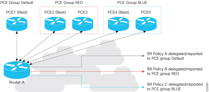
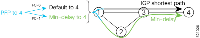
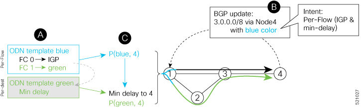
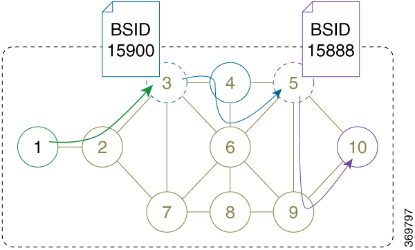
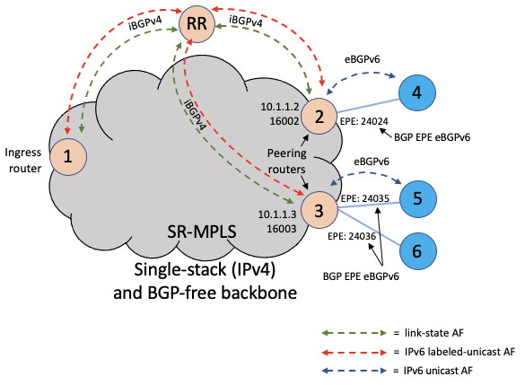

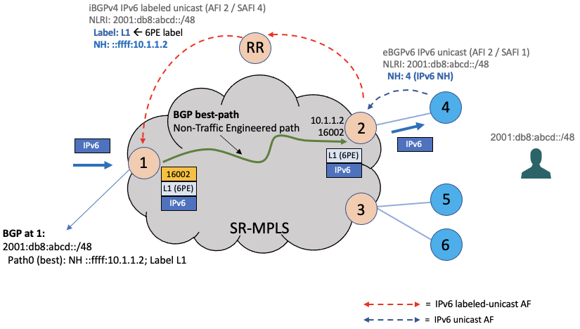
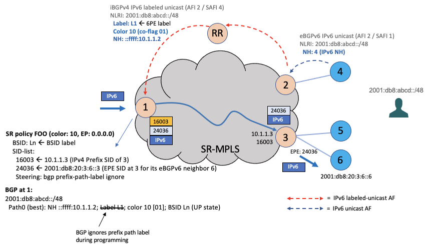
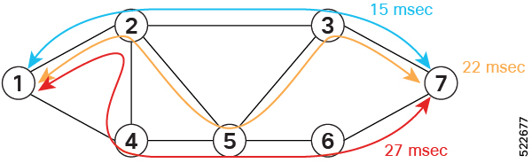
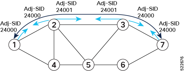
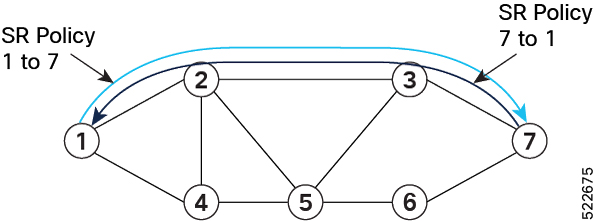

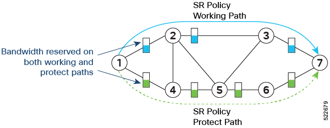
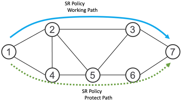
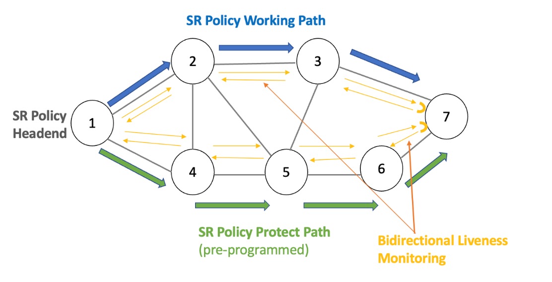
 Feedback