Configure Segment Routing over IPv6 (SRv6) with Micro-SIDs


Note


IOS XR release 7.3.2 supports SRv6 with Full-length SID and Micro-SID formats; however, only one format is supported in the network at a time.

To use SRv6 Micro-SID (uSID), enter the hw-module profile segment-routing srv6 mode micro-segment format f3216 command in config mode, then reload the router or line card. See Configuring SRv6 for more information.

To use SRv6 Full-length SID, see the Configure Segment Routing over IPv6 (SRv6) with Full-Length SIDs.


Segment Routing for IPv6 (SRv6) is the implementation of Segment Routing over the IPv6 dataplane.

Segment Routing over IPv6 Overview

Segment Routing (SR) can be applied on both MPLS and IPv6 data planes. Segment Routing over IPv6 (SRv6) extends Segment Routing support with IPv6 data plane.

In an SR-MPLS enabled network, an MPLS label represents an instruction. The source nodes programs the path to a destination in the packet header as a stack of labels.

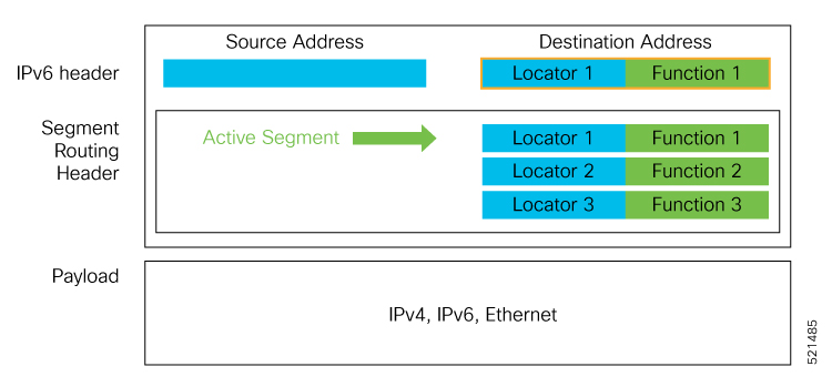
SRv6 introduces the Network Programming framework that enables a network operator or an application to specify a packet processing program by encoding a sequence of instructions in the IPv6 packet header. Each instruction is implemented on one or several nodes in the network and identified by an SRv6 Segment Identifier (SID) in the packet. The SRv6 Network Programming framework is defined in IETF RFC 8986 SRv6 Network Programming.

In SRv6, an IPv6 address represents an instruction. SRv6 uses a new type of IPv6 Routing Extension Header, called the Segment Routing Header (SRH), in order to encode an ordered list of instructions. The active segment is indicated by the destination address of the packet, and the next segment is indicated by a pointer in the SRH.

Figure 1. Network Program in the Packet Header

The SRv6 SRH is documented in IETF RFC IPv6 Segment Routing Header (SRH).

The SRH is defined as follows:


     0                   1                   2                   3
     0 1 2 3 4 5 6 7 8 9 0 1 2 3 4 5 6 7 8 9 0 1 2 3 4 5 6 7 8 9 0 1
    +-+-+-+-+-+-+-+-+-+-+-+-+-+-+-+-+-+-+-+-+-+-+-+-+-+-+-+-+-+-+-+-+
    | Next Header   |  Hdr Ext Len  | Routing Type  | Segments Left |
    +-+-+-+-+-+-+-+-+-+-+-+-+-+-+-+-+-+-+-+-+-+-+-+-+-+-+-+-+-+-+-+-+
    |  Last Entry   |     Flags     |              Tag              |
    +-+-+-+-+-+-+-+-+-+-+-+-+-+-+-+-+-+-+-+-+-+-+-+-+-+-+-+-+-+-+-+-+
    |                                                               |
    |            Segment List[0] (128-bit IPv6 address)             |
    |                                                               |
    |                                                               |
    +-+-+-+-+-+-+-+-+-+-+-+-+-+-+-+-+-+-+-+-+-+-+-+-+-+-+-+-+-+-+-+-+
    |                                                               |
    |                                                               |
                                  ...
    |                                                               |
    |                                                               |
    +-+-+-+-+-+-+-+-+-+-+-+-+-+-+-+-+-+-+-+-+-+-+-+-+-+-+-+-+-+-+-+-+
    |                                                               |
    |            Segment List[n] (128-bit IPv6 address)             |
    |                                                               |
    |                                                               |
    +-+-+-+-+-+-+-+-+-+-+-+-+-+-+-+-+-+-+-+-+-+-+-+-+-+-+-+-+-+-+-+-+
    //                                                             //
    //         Optional Type Length Value objects (variable)       //
    //                                                             //
    +-+-+-+-+-+-+-+-+-+-+-+-+-+-+-+-+-+-+-+-+-+-+-+-+-+-+-+-+-+-+-+-+

The following list explains the fields in SRH:

  • Next header—Identifies the type of header immediately following the SRH.

  • Hdr Ext Len (header extension length)—The length of the SRH in 8-octet units, not including the first 8 octets.

  • Segments left—Specifies the number of route segments remaining. That means, the number of explicitly listed intermediate nodes still to be visited before reaching the final destination.

  • Last Entry—Contains the index (zero based) of the last element of the segment list.

  • Flags— Contains 8 bits of flags.

  • Tag—Tag a packet as part of a class or group of packets like packets sharing the same set of properties.

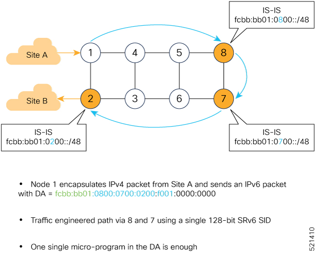
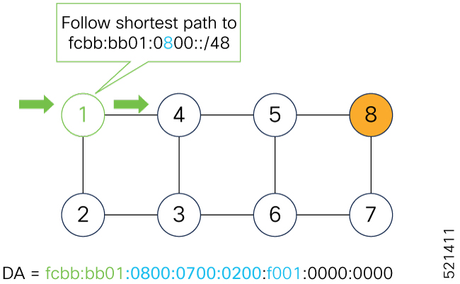
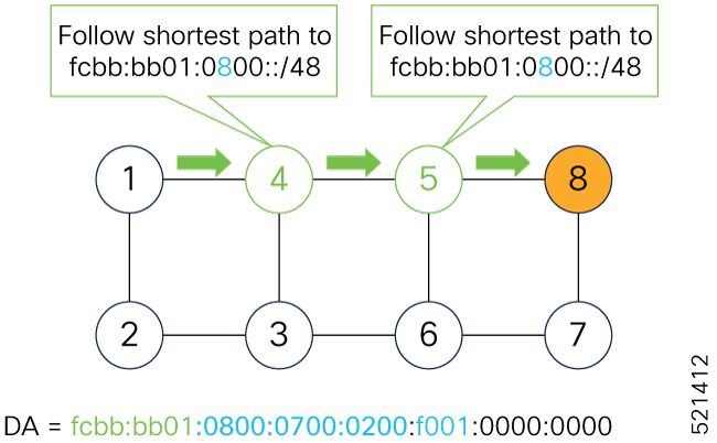
  • Segment list—128-bit IPv6 addresses representing the nth segment in the segment list. The segment list encoding starts from the last segment of the SR policy (path). That means the first element of the segment list (Segment list [0]) contains the last segment of the SR policy, the second element contains the penultimate segment of the SR policy and so on.

In SRv6, a SID represents a 128-bit value, consisting of the following three parts:

  • Locator: This is the first part of the SID with most significant bits and represents an address of a specific SRv6 node.

  • Function: This is the portion of the SID that is local to the owner node and designates a specific SRv6 function (network instruction) that is executed locally on a particular node, specified by the locator bits.

  • Args: This field is optional and represents optional arguments to the function.

The locator part can be further divided into two parts:

  • SID Block: This field is the SRv6 network designator and is a fixed or known address space for an SRv6 domain. This is the most significant bit (MSB) portion of a locator subnet.

  • Node Id: This field is the node designator in an SRv6 network and is the least significant bit (LSB) portion of a locator subnet.

SRv6 Node Roles

Each node along the SRv6 packet path has a different functionality:

  • Source node—A node that can generate an IPv6 packet with an SRH (an SRv6 packet), or an ingress node that can impose an SRH on an IPv6 packet.

  • Transit node—A node along the path of the SRv6 packet (IPv6 packet and SRH). The transit node does not inspect the SRH. The destination address of the IPv6 packet does not correspond to the transit node.

  • Endpoint node—A node in the SRv6 domain where the SRv6 segment is terminated. The destination address of the IPv6 packet with an SRH corresponds to the end point node. The segment endpoint node executes the function bound to the SID

SRv6 Head-End Behaviors

The SR Headend with Encapsulation behaviors are documented in the IETF RFC 8986 SRv6 Network Programming.

The SR Headend with Insertion head-end behaviors are documented in the following IETF draft:

https://datatracker.ietf.org/doc/draft-filsfils-spring-srv6-net-pgm-insertion/

This section describes a set of SR Policy headend behaviors. The following list summarizes them:

  • H.Encaps—SR Headend Behavior with Encapsulation in an SRv6 Policy

  • H.Encaps.Red—H.Encaps with Reduced Encapsulation

  • H.Insert—SR Headend with insertion of an SRv6 Policy

  • H.Insert.Red—H.Insert with reduced insertion

SRv6 Endpoint Behaviors

The SRv6 endpoint behaviors are documented in the IETF RFC 8986 SRv6 Network Programming.

The following is a subset of defined SRv6 endpoint behaviors that can be associated with a SID.

  • End—Endpoint function. The SRv6 instantiation of a Prefix SID [RFC8402].

  • End.X—Endpoint with Layer-3 cross-connect. The SRv6 instantiation of an Adj SID [RFC8402].

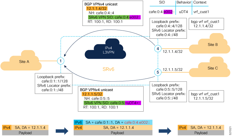
  • End.DX6—Endpoint with decapsulation and IPv6 cross-connect (IPv6-L3VPN - equivalent to per-CE VPN label).

  • End.DX4—Endpoint with decapsulation and IPv4 cross-connect (IPv4-L3VPN - equivalent to per-CE VPN label).

  • End.DT6—Endpoint with decapsulation and IPv6 table lookup (IPv6-L3VPN - equivalent to per-VRF VPN label).

  • End.DT4—Endpoint with decapsulation and IPv4 table lookup (IPv4-L3VPN - equivalent to per-VRF VPN label).

  • End.DT46—Endpoint with decapsulation and specific IP table lookup (IP-L3VPN - equivalent to per-VRF VPN label).

  • End.DX2—Endpoint with decapsulation and L2 cross-connect (L2VPN use-case).

  • End.B6.Encaps—Endpoint bound to an SRv6 policy with encapsulation. SRv6 instantiation of a Binding SID.

  • End.B6.Encaps.RED—End.B6.Encaps with reduced SRH. SRv6 instantiation of a Binding SID.

SRv6 Endpoint Behavior Variants

Depending on how the SRH is handled, different behavior variants are defined for the End and End.X behaviors. The End and End.X behaviors can support these variants, either individually or in combinations.

  • Penultimate Segment Pop (PSP) of the SRH variant—An SR Segment Endpoint Nodes receive the IPv6 packet with the Destination Address field of the IPv6 Header equal to its SID address.

    A penultimate SR Segment Endpoint Node is one that, as part of the SID processing, copies the last SID from the SRH into the IPv6 Destination Address and decrements the Segments Left value from one to zero.

    The PSP operation takes place only at a penultimate SR Segment Endpoint Node and does not happen at non-penultimate endpoint nodes. When a SID of PSP-flavor is processed at a non-penultimate SR Segment Endpoint Node, the PSP behavior is not performed since Segments Left would not be zero.

    The SR Segment Endpoint Nodes advertise the SIDs instantiated on them via control plane protocols. A PSP-flavored SID is used by the Source SR Node when it needs to instruct the penultimate SR Segment Endpoint Node listed in the SRH to remove the SRH from the IPv6 header.

  • Ultimate Segment Pop (USP) of the SRH variant—The SRH processing of the End and End.X behaviors are modified as follows:

    If Segments Left is 0, then:

    1. Update the Next Header field in the preceding header to the Next Header value of the SRH

    2. Decrease the IPv6 header Payload Length by 8*(Hdr Ext Len+1)

    3. Remove the SRH from the IPv6 extension header chain

    4. Proceed to process the next header in the packet

    One of the applications of the USP flavor is when a packet with an SRH is destined to an application on hosts with smartNICs implementing SRv6. The USP flavor is used to remove the consumed SRH from the extension header chain before sending the packet to the host.

  • Ultimate Segment Decapsulation (USD) variant—The Upper-layer header processing of the End and End.X behaviors are modified as follows:

    • End behavior: If the Upper-layer Header type is 41 (IPv6), then:

      1. Remove the outer IPv6 Header with all its extension headers

      2. Submit the packet to the egress IPv6 FIB lookup and transmission to the new destination

      3. Else, if the Upper-layer Header type is 4 (IPv4)

      4. Remove the outer IPv6 Header with all its extension headers

      5. Submit the packet to the egress IPv4 FIB lookup and transmission to the new destination

      6. Else, process as per Section 4.1.1 (Upper-Layer Header) of IETF RFC 8986 SRv6 Network Programming

    • End.X behavior: If the Upper-layer Header type is 41 (IPv6) or 4 (IPv4), then:

      1. Remove the outer IPv6 Header with all its extension headers

      2. Forward the exposed IP packet to the L3 adjacency J

      3. Else, process as per Section 4.1.1 (Upper-Layer Header) of IETF RFC 8986 SRv6 Network Programming

    One of the applications of the USD flavor is the case of TI-LFA in P routers with encapsulation with H.Encaps. The USD flavor allows the last Segment Endpoint Node in the repair path list to decapsulate the IPv6 header added at the TI-LFA Point of Local Repair and forward the inner packet.

SRv6 Micro-Segment (uSID)

Table 1. Feature History Table

Feature Name

Release Information

Feature Description

Cisco NC57 Native Mode: SRv6 Micro-Segment (uSID)

Release 7.5.2

SRv6 Micro-Segment (uSID) is an extension of the SRv6 architecture. It leverages the existing SRv6 Network Programming architecture to encode up to six SRv6 Micro-SID (uSID) instructions within a single 128-bit SID address. Such a SID address is called a uSID Carrier.

The following features are now supported on Cisco NCS 5700 series fixed port routers and the Cisco NCS 5500 series routers that have Cisco NC57 line cards installed and operating in the native mode:

SRv6 Micro-Segment (uSID)

Release 7.3.1

This feature is an extension of the SRv6 architecture. It leverages the existing SRv6 Network Programming architecture to encode up to six SRv6 Micro-SID (uSID) instructions within a single 128-bit SID address. Such a SID address is called a uSID Carrier.

In addition, this feature leverages the existing SRv6 data plane and control plane with no changes. It also provides low MTU overhead; for example, 6 uSIDs per uSID carrier results in 18 source-routing waypoints in only 40 bytes of overhead (in SRH).

The SRv6 micro-segment (uSID) is an extension of the SRv6 architecture. It leverages the SRv6 Network Programming architecture to encode several SRv6 Micro-SID (uSID) instructions within a single 128-bit SID address. Such a SID address is called a uSID Carrier.

SRv6 uSID is documented in the IETF drafts Network Programming extension: SRv6 uSID instruction and Compressed SRv6 Segment List Encoding in SRH.

Throughout this chapter, we will refer to SRv6 micro-segment as “uSID”.

The SRv6 uSID provides the following benefits:

  • Leverages the SRv6 Network Programming with no change. SRv6 uSID is a new pseudo code in the existing SRv6 network programming framework.

  • Leverages the SRv6 data plane (SRH) with no change. Any SID in the destination address or SRH can be an SRv6 uSID carrier.

  • Leverages the SRv6 control plane with no change.

  • Ultra-Scale—Scalable number of globally unique nodes in the domain, for example:

    • 16-bit uSID ID size: 65k uSIDs per domain block

    • 32-bit uSID ID size: 4.3M uSIDs per domain block

  • Lowest MTU overhead

    • 6 uSIDs per uSID carrier

    • For example, 18 source-routing waypoints in only 40 bytes of overhead

  • Hardware-friendliness:

    • Leverages mature hardware capabilities (inline IP Destination Address edit, IP Destination Address longest match).

    • Avoids any extra lookup in indexed mapping tables.

    • A micro-program with 6 or fewer uSIDs requires only legacy IP-in-IP encapsulation behavior.

  • Scalable Control Plane:

    • Summarization at area/domain boundary provides massive scaling advantage.

    • No routing extension is required, a simple prefix advertisement suffices.

  • Seamless Deployment:

    • A uSID may be used as a SID (the carrier holds a single uSID).

    • The inner structure of an SR Policy can stay opaque to the source. A carrier with uSIDs is just seen as a SID by the policy headend Security.

    • Leverages SRv6's native SR domain security.

SRv6 uSID Terminology

The SRv6 Network Programming is extended with the following terms:

  • uSID—An identifier that specifies a micro-segment.

    A uSID has an associated behavior that is the SRv6 function (for example, a node SID or Adjacency SID) associated with the given ID. The node at which an uSID is instantiated is called the “Parent” node.

  • uSID Carrier—A 128-bit IPv6 address (carried in either in the packet destination address or in the SRH) in the following format:

    <uSID-Block><Active-uSID><Next-uSID>...<Last-uSID><End-of-Carrier>...<End-of-Carrier>

    where:

    • uSID Block—An IPv6 prefix that defines a block of SRv6 uSIDs.

    • Active uSID—The first uSID that follows the uSID block.

    • Next uSID—The next uSID after the Active uSID.

    • Last uSID—The last uSID in the carrier before the End-of-Carrier uSID.

    • End-of-Carrier —A globally reserved uSID that marks the end of a uSID carrier. The End-of-Carrier ID is 0000. All empty uSID carrier positions must be filled with the End-of-Carrier ID; therefore, a uSID carrier can have more than one End-of-Carrier.

    The following is an example of an SRH with 3 Micro-SID carriers for a total of up to 18 micro-instructions:

    Micro-SID Carrier1: {uInstruction1, uInstruction2… uInstruction6}

    Micro-SID Carrier2: {uInstruction7, uInstruction8… uInstruction12}

    Micro-SID Carrier3: {uInstruction13, uInstruction14… uInstruction18}

SRv6 uSID Carrier Format

The uSID carrier format specifies the type of uSID carrier supported in an SRv6 network. The format specification includes Block size and ID size.

  • uSID Block

    The uSID block is an IPv6 prefix that defines a block of SRv6 uSIDs. This can be an IPv6 prefix allocated to the provider (for example, /22, /24, and so on.), or it can be any well-known IPv6 address block generally available for private use, such as the ULA space FC/8, as defined in IETF draft RFC4193.

    An SRv6 network may support more than a single uSID block.

    The length of block [prefix] is defined in bits. From a hardware-friendliness perspective, it is expected to use sizes on byte boundaries (16, 24, 32, and so on).

  • uSID ID

    The length of uSID ID is defined in bits. From a hardware-friendliness perspective, it is expected to use sizes on byte boundaries (8, 16, 24, 32, and so on).

The uSID carrier format is specified using the notation "Fbbuu" , where “bb” is size of block and “uu” is size of ID. For example, "F3216" is a format with a 32-bit uSID block and 16-bit uSID IDs.


Note


F3216 is the default format, and the only format that is supported in IOS XR 7.3.1 release.

SRv6 uSID Allocation Within a uSID Block

The architecture for uSID specifies both globally scoped and locally scoped uSIDs, where a globally scoped uSID is the type of uSID that provides reachability to the node.

On the other hand, a locally scoped uSID is associated to a local behavior, and therefore must be preceded by a globally scoped uSID of the parent node when relying on routing to forward the packet.

The Global ID block (GIB) is the set of IDs available for globally scoped uSID allocation. The Local ID block (LIB) is the set of IDs available for locally scoped uSID allocation.

A globally scoped uSID is a uSID from the GIB. A globally scoped uSID typically identifies a shortest path to a node in the SR domain. An IP route (for example, /48) is advertised by the parent node to each of its globally scoped uSIDs, under the associated uSID block. The parent node executes a variant of the END behavior.

The “Nodal” uSID (uN) is an example of a globally scoped behavior defined in uSID architecture.

A node can have multiple globally scoped uSIDs under the same uSID blocks (for example, one per IGP flex-algorithm). Multiple nodes may share the same globally scoped uSID (Anycast).

A locally scoped uSID is a uSID from the LIB. A locally scoped uSID identifies a local micro-instruction on the parent node; for example, it may identify a cross-connect to a direct neighbor over a specific interface or a VPN context. Locally scoped uSIDs are not routeable.

For example, if N1 and N2 are two different physical nodes of the uSID domain and L is a locally scoped uSID value, then N1 and N2 may bind two different behaviors to L.

The uSIDs are allocated in one of following ways: auto, dynamic, or explicit.

  • The request to allocate locally scoped uSIDs comes from SRv6 clients (such as IS-IS or BGP). The request can be to allocate any available ID (dynamic allocation) or to allocate a specific ID (explicit allocation).

SRv6 Endpoint Behaviors Associated with uSID

The SRv6 Network Programming is extended with new types of SRv6 SID endpoint behaviors:

  • uN—A short notation for the NEXT-CSID (Compressed SID) End behavior with a pseudocode of shift-and-lookup, and PSP/USD flavors

  • uA—A short notation for the NEXT-CSID End.X behavior with a pseudocode of shift-and-xconnect, and PSP/USD flavors

  • uDT—A short notation for the NEXT-CSID End.DT behavior with the same pseudocode as End.DT4/End.DT6/End.DT46/End.DT2U/End.DT2M

  • uDX—A short notation for the NEXT-CSID End.DX behavior with the same pseudocode as End.DX4/End.DX6/End.DX2

SRv6 uSID in Action - Example

This example highlights an integrated VPN and Traffic Engineering use-case leveraging SRv6 uSID.

VPNv4 site A connected to Node 1 sends packets to VPNv4 site B connected to Node 2 alongside a traffic engineered path via Node 8 and Node 7 using a single 128-bit SRv6 SID.

Node 1 is the ingress PE; Node 2 is the egress PE.

Nodes 3, 4, 5, and 6 are classic IPv6 nodes. Traffic received on these nodes use classic IP forwarding without changing the outer DA.

Nodes 1, 8, 7 and 2 are SRv6 capable configured with:

  • 32-bit SRv6 block = fcbb:bb01

  • 16-bit SRv6 ID

    For example:

    • Node 7 uN = fcbb:bb01:0700::/48

    • Node 8 uN = fcbb:bb01:0800::/48

The following IGP routes are advertised:

  • Node 8 advertises the IGP route fcbb:bb01:0800::/48

  • Node 7 advertises the IGP route fcbb:bb01:0700::/48

  • Node 2 advertises the IGP route fcbb:bb01:0200::/48

Figure 2. Integrated VPN and Traffic Engineering SRv6 uSID Use-case

Node 1 encapsulates an IPv4 packet from VPN Site A and sends an IPv6 packet with destination address fcbb:bb01:0800:0700:0200:f001:0000:0000. This is a uSID carrier, with a list of micro-instructions (uSIDs) (0800, 0700, 0200, f001, and 0000 – indicating the end of the instruction).

uSIDs (uNs) 0800, 0700, 0200 are used to realize the traffic engineering path to Node 2 with way points at Nodes 8 and 7. uSID f001 is the BGP-signalled instruction (uDT4) advertized by Node 2 for the VPNv4 service

Figure 3. Node 1: End.B6.Encaps Behavior

Nodes 4 and 5 simply forward the packet along the shortest path to Node 8, providing seamless deployment through classic IPv6 nodes.

Figure 4. Node 4 and Node 5: Classic IPv6 Nodes

When Node 8 receives the packet, it performs SRv6 uN behavior (shift-and-lookup with PSP/USD). It removes its outer DA (0800) and advances the micro program to the next micro instruction by doing the following:

  1. Pops its own uSID (0800)

  2. Shifts the remaining DA by 16-bits to the left

  3. Fills the remaining bits with 0000 (End-of-Carrier)

  4. Performs a lookup for the shortest path to the next DA (fcbb:bb01:0700::/48)

  5. Forwards it using the new DA fcbb:bb01:0700:0200:f001:0000:0000:0000

Figure 5. Node 8: SRv6 uN Behavior (Shift and Forward)

When Node 7 receives the packet, it performs the same SRv6 uN behavior (shift-and-lookup with PSP/USD), forwarding it using the new DA fcbb:bb01:0200:f001:0000:0000:0000:0000

Figure 6. Node 7: SRv6 uN Behavior (Shift and Forward)

Nodes 6 and 3 simply forward the packet along the shortest path to Node 2, providing seamless deployment through classic IPv6 nodes.

Figure 7. Node 6 and Node 3: Classic IPv6 Nodes

When Node 2 receives the packet, it performs an SRv6 uDT4 behavior (End.DT4—Endpoint with decapsulation and IPv4 table lookup) to VPNv4 Site B.

Figure 8. Node 2: SRv6 uDT4 Behavior

To recap, this example showed an integrated VPN and Traffic Engineering use-case, where VPNv4 site A connected to Node 1 sent packets to VPNv4 site B connected to Node 2 alongside a traffic engineered path via Node 8 and Node 7 using a single 128-bit SRv6 SID:

  • @1: inner packet P encapsulated with outer DA fcbb:bb01:0800:0700:0200:f001:0000:0000

  • @4 & @5: classic IP forwarding, outer DA unchanged

  • @8: SRv6 uN behavior: shift and lookup, outer DA becomes fcbb:bb01:0700:0200:f001:0000:0000:0000

  • @7: SRv6 uN behavior: shift and lookup, outer DA becomes fcbb:bb01:0200:f001:0000:0000:0000:0000

  • @6 & @3: classic IP forwarding, outer DA unchanged

  • @2: SRv6 End.DT4: Decapsulate and IPv4 table lookup

Usage Guidelines and Limitations

General Guidelines and Limitations

  • Cisco IOS XR supports uSIDs with 32-bit uSID block and 16-bit uSID IDs (3216).

    A single UCF format must be used for uSID locators in a SRv6 uSID domain.

  • Cisco IOS XR supports up to 8 uSID locator prefixes.

    Multiple locator prefixes are used when configuring Anycast locators or SRv6 Flexible Algorithm instances, for example.

  • Cisco IOS XR supports uSID locator prefixes from different uSID blocks.

    Up to 64 uSID blocks can be used across all uSID locators in the network.

  • Cisco IOS XR Release 7.3.1 and later supports the following SRv6 uSID behaviors and variants:

    • uN with PSP/USD

    • uA with PSP/USD

    • uDT4

    • uDT6

  • SRv6 Underlay support includes:

    • IGP redistribution/leaking between levels

    • Prefix Summarization on ABR routers

    • IS-IS TI-LFA

    • Microloop Avoidance

    • Flex-algo

  • SRv6 over GRE interface is not supported

  • SRv6 over BVI interface is not supported

uSID Allocation Recommendation

We recommend that the uSID block allocation is made from the IPv6 Unique Local Address (ULA) range.


Note


Allocation from the public Global Unicast Addresses (GUA) range is also supported.
  • Use ULA /24 base from FC00::/8 space

    • FCBB:BB/24, with B indicating a nibble value picked by operator

  • 256 uSID blocks possible from this allocation

    • In this release, 64 uSID blocks are supported

    • FCBB:BBVV/32, with VV two variable nibbles. The supported values for VV in Cisco IOS XR Release 7.3.1 are 0x00 to 0x3F.

For example:

  • ULA /24 base = FC00:01/24

  • uSID block space = 64 uSID blocks (from FC00:0100/32 to FC00:013F/32)

Platform-Specific Guidelines and Limitations

SRv6 is supported on NCS 5500 series routers and NCS 5700 series routers/NC57 line cards.

This release supports the following SID Encap budget:

  • P role:

    • Underlay H-Insert: 6 sids (1 carrier with 6 sids per carrier)

  • PE role:

    • Underlay H-Insert: 3 sids (1 carrier with 3 sids per carrier)

    • Overlay H-Encaps: 3 sids (1 carrier with 3 sids per carrier)

Configuring SRv6

Table 2. Feature History Table

Feature Name

Release Information

Feature Description

SRv6 Traffic Class DSCP Marking Enhancement for QoS

Release 24.2.1

Introduced in this release on: NCS 5500 fixed port routers; NCS 5500 modular routers

This feature allows you to set the traffic class values to use the full range of DSCP (6 bits) for SRv6 packets that are encapsulated.

The feature extends the existing policy-map setting of 3-bit traffic class DSCP marking to 6 bits using the new policy-map-extend option in the configuration for L2 and L3 traffic for SRv6.

This is a mutually inclusive feature for L2 and L3 traffic. Therefore, this feature cannot be used in the individual configuration for L2 and L3 traffic.

This feature introduces this change:

CLI: The policy-map-extend keyword is introduced in the hw-module profile segment-routing srv6 mode microsegment f3216 encapsulation traffic-class command.

SRv6 Traffic Class QoS Enhancement

Release 7.7.1

The modified hw-module profile segment-routing srv6 mode command option provides you with better flexibility to customize the optional SRv6 encapsulation parameters. The updated command supports both L2 and L3 traffic types of SRv6 parameters.

Encapsulation is a sub-mode from Release 7.7.1.

The l3-traffic configuration supports the additional policy-map option that sets SRv6 traffic-class DSCP based on qos-group selected by input policy-map.

The following commands are updated:

The following commands are introduced:

Enabling SRv6 involves the following high-level configuration steps:

  • Enable SRv6 on the platform

  • Configure SRv6 locator(s)

  • Enable SRv6 under IS-IS

  • Enable SRv6 Services under BGP

Enable SRv6 on the Platform

Before configuring SRv6 on the Cisco NCS 5500 Series Routers router, you must first use the following command:

  • hw-module profile segment-routing srv6 mode micro-segment format f3216


    Note


    You must reload the router after enabling this command.
(Optional) Configure Network Role

By default, after enabling SRv6 on the platform, the node can serve as both edge (services) and core roles.

Optionally, you can customize the node role as "core-only" using the following command:

  • hw-module profile network-role core-only


    Note


    You must reload the router after enabling this command.

Given that there is different budget for underlay SID encap based on the node role in the network (P-only vs Edge), an operator can use this configuration to provide a hint to the platform and control plane to use a larger SID encap budget when operating as a P-only node.

(Optional) Configure Merge Overlay/Underlay SID Mode

One of the main benefits of SRv6 uSID is compression (or packing) of multiple uSIDs into a uSID carrier. This is possible when they share the same uSID block and when there is enough space in the carrier.

The underlay SIDs are always programmed in compressed form, if possible. The overlay SID is programmed separately.

The segment-routing srv6 micro-segment merge-overlay-underlay-sids command is used to enable the platform to merge overlay/underlay SIDs.


Note


From Cisco IOS XR Release 7.7.1 and later, the compression/merging of uSID lists is automatically done in the dataplane during imposition. This configuration option is ignored by the dataplane.


When there is a need to send overlay traffic, the data path implementation attempts to merge the underlay SIDs and overlay SIDs into a single carrier, if possible. With H.Encaps.Red encapsulation, this yields a packet with no SRH.


Note


If the overlay and underlay use different uSID blocks, this merge is not possible.

By default, the Cisco NCS platform does not automatically merge the overlay/underlay SIDs.

To enable the platform to merge overlay/underlay SIDs, use the following command:

  • segment-routing srv6 micro-segment merge-overlay-underlay-sids


    Caution


    This command should only be enabled when a single block is required.

After you enable this command, this CLI will modify the behavior for all new overlay routes being programmed afterwards.

If you enable this command after SRv6 overlay routes are already programmed, we recommend that you clear the SRv6 overlay routes (using the clear route [vrf WORD] command) in order to trigger the re-programming in the “merge” mode.

If you do not to clear the overlay routes, those routes would continue to be programmed in the “non-merge” mode.

(Optional) Customize SRv6 Encapsulation Parameters

From Cisco IOS XR Release 7.7.1, the hw-module profile segment-routing srv6 mode command has been updated to support both L2 and L3 traffic types of SRv6 parameters. The existing traffic-class CLI (common to L2 and L3) is still accepted in the ASCII format, but will be converted into the new l2-traffic and l3-traffic submode format after the config is committed.

From Cisco IOS XR Release 7.7.1, ensure that you use mandatory keyword mode . Note that encapsulation is now a sub-mode and not a configuration option.

The following example shows how to configure the traffic-class field settings on the IPv6 header:

Router(config)#hw-module profile segment-routing srv6 mode micro-segment format f3216 
Router(config-srv6)#encapsulation 
Router(config-srv6-encap)#l2-traffic                         
Router(config-srv6-encap-l2)#traffic-class propagate 

Router(config)#hw-module profile segment-routing srv6 mode micro-segment format f3216
Router(config-srv6)#encapsulation 
Router(config-srv6-encap)#l3-traffic 
Router(config-srv6-encap-l3)#traffic-class policy-map

Router(config)#hw-module profile segment-routing srv6 mode micro-segment format f3216 
Router(config-srv6)#encapsulation
Router(config-srv6-encap)#traffic-class policy-map-extend

The l2-traffic and l3-traffic are SRv6 parameters for L2 traffic type and L3 traffic type respectively. The traffic-class parameter controls the traffic-class field of SRv6 IPv6 header for inner L2 and L3 traffic. Use propagate to set the traffic-class value by propagation (from incoming packet/frame). Use policy-map to set traffic-class DSCP to qos-group selected by input policy-map.

The l3-traffic configuration supports the additional policy-map option that sets SRv6 traffic-class DSCP based on qos-group selected by input policy-map .

The l2-traffic configuration continues to support the propagate option that sets the SRv6 traffic-class based on either the inner packet (default) or input policy-map (if match action found).

Starting with Cisco IOS XR Software Release 24.2.1, both the L2 and L3 traffic configurations support the policy-map-extend option to set the SRv6 traffic-class DSCP marking to 6 bits. This is a mutually inclusive feature for L2 and L3 traffic. Therefore, this feature cannot be used in the individual configuration for L2 and L3 traffic.

When you use the policy-map-extend keyword in the hw-module profile segment-routing srv6 mode microsegment f3216 encapsulation traffic-class CLI, the existing 3-bit DSCP marking set by the hw-module profile segment-routing srv6 mode microsegment f3216 encapsulation traffic-class l3-traffic policy-map CLI in the L3 traffic configuration is modified to 6-bits.

Go through the following topics for more information on the CLI:

Specify the value (as 2 hexadecimal nibbles) for traffic class; valid values are from 0x0 to 0xff.

Configure SRv6 Locator Name, Prefix, and uSID-Related Parameters

This section shows how to globally enable SRv6 and configure locator.

  • segment-routing srv6 locators locator locator—Globally enable SRv6 and configure the locator.

  • segment-routing srv6 locators locator locator prefix ipv6_prefix/length—Configure the locator prefix value.

  • segment-routing srv6 locators locator locator micro-segment behavior unode psp-usd—Specifies the locator as a micro-segment (uSID) locator as well as specifies that IGP underlay uSID (uN/uA) variant is PSP-USD for this locator.

(Optional) Configure Algorithm Associated with Locator

(Optional) Configure Anycast Locator

An SRv6 Anycast locator is a type of locator that identifies a set of nodes (uN SIDs). SRv6 Anycast Locators and their associated uN SIDs may be provisioned at multiple places in a topology.

The set of nodes (Anycast group) is configured to advertise a shared Anycast locator and uN SID. Anycast routing enables the steering of traffic toward multiple advertising nodes. Packets addressed to an Anycast address are forwarded to the topologically nearest nodes.

One use case is to advertise Anycast uN SIDs at exit points from an SRv6 network. Any of the nodes that advertise the common uN SID could be used to forward traffic out of the SRv6 portion of the network to the topologically nearest node.

The following behaviors apply to Anycast Locator:

  • Unlike a normal locator, IS-IS does not program or advertise uA SIDs associated with an Anycast locator.

  • uN SIDs allocated from Anycast locators will not be used in constructing TI-LFA backup paths or Microloop Avoidance primary paths. TI-LFA backup and Microloop Avoidance paths for an Anycast locator prefix may terminate on any node advertising that locator, which may be different from the node terminating the original primary path.

  • SRv6 anycast locators may have non-zero algorithm (Flexible Algorithm) values.

Use the following commands to configure the Anycast locator and advertise Anycast prefixes associated with an interface.

  • segment-routing srv6 locators locator locator anycast—Configure the Anycast locator

  • router isis instance-id interface Loopback instance prefix-attributes anycast level level—Advertise the Anycast prefixes associated with an interface.

Example 1:

The following example shows how to globally enable SRv6 and configure a locator.

Router(config)# segment-routing srv6
Router(config-srv6)# locators
Router(config-srv6-locators)# locator myLoc1
Router(config-srv6-locator)# micro-segment behavior unode psp-usd
Router(config-srv6-locator)# prefix 2001:0:8::/48

Example 2:

The following example shows how to configure Flexible Algorithm associated with locator.

Router(config)# segment-routing srv6
Router(config-srv6)# locators
Router(config-srv6-locators)# locator myLocAlgo128
Router(config-srv6-locator)# algorithm 128
Router(config-srv6-locator)# micro-segment behavior unode psp-usd
Router(config-srv6-locator)# prefix 2001:0:88::/48

Example 3:

The following example shows how to configure Anycast locator.

Router(config)# segment-routing srv6
Router(config-srv6)# locators
Router(config-srv6-locators)# locator myLocAnycast
Router(config-srv6-locator)# anycast
Router(config-srv6-locator)# micro-segment behavior unode psp-usd
Router(config-srv6-locator)# prefix 2001:0:100::/48

The following example shows how to advertise the Anycast prefixes associated with an interface.

Router(config)# router isis core
Router(config-isis)# interface Loopback100
Router(config-isis-if)# prefix-attributes anycast level 1

(Optional) Customize SRv6 Encapsulation Parameters

This section describes the configurable SRv6 encapsulation parameters. These optional parameters include:

  • segment-routing srv6 encapsulation source-address ipv6-addr—Source Address of outer encapsulating IPv6 header. The default source address for encapsulation is one of the loopback addresses.

  • segment-routing srv6 encapsulation hop-limit {count | propagate}—The hop limit of outer-encapsulating IPv6 header. The range for count is from 1 to 254 for NCS 5500 and from 1 to 255 for NCS 5700; the default value for hop-limit is 254. Use propagate to set the hop-limit value by propagation (from incoming packet/frame).


    Note


    On NCS 5700 hardware, hop-limit propagation is not applied for packets going to P2P services.


  • segment-routing srv6 encapsulation evpn next-header protocol-number—The protocol number to use in the Next-header field of the IPv6 or SRH header. The range for protocol-number is from 59 to 252.

(Optional) Customize SRv6 Logging for Locator Status Changes

  • segment-routing srv6 logging locator status—Enable the logging of locator status.

(Optional) Customize SRv6 SID Parameters

  • segment-routing srv6 sid holdtime minutes—The holdtime for a stale or freed SID. The range of minutes is from 0 (disabled) to 60 minutes.

Example 4:

The following example shows how to configure optional SRv6 parameters:

RP/0/RSP0/CPU0:Node1(config)# segment-routing srv6 encapsulation
RP/0/RSP0/CPU0:Node1(config-srv6-encap)# source-address 1::1
RP/0/RSP0/CPU0:Node1(config-srv6-encap)# hop-limit 60
RP/0/RSP0/CPU0:Node1(config-srv6-encap)# evpn next-header 65
RP/0/RSP0/CPU0:Node1(config-srv6-encap)# exit
RP/0/RSP0/CPU0:Node1(config-srv6)# logging locator status
RP/0/RSP0/CPU0:Node1(config-srv6)# sid holdtime 10
RP/0/RSP0/CPU0:Node1(config-srv6)# micro-segment merge-overlay-underlay-sids

This config applies to only new SRv6 micro-segment overlay routes and does not update already programmed routes. 
Please flap any existing SRv6 micro-segment overlay routes after making this configuration change.

RP/0/RSP0/CPU0:Node1(config-srv6)#

Verifying SRv6 Manager

This example shows how to verify the overall SRv6 state from SRv6 Manager point of view. The output displays parameters in use, summary information, and platform specific capabilities.

Router# show segment-routing srv6 manager 
Parameters:
  SRv6 Enabled: Yes
  SRv6 Operational Mode:
    Micro-segment:
      SID Base Block: 2001::/24
  Encapsulation:
    Source Address:
      Configured: ::
      Default: ::
    Hop-Limit: Default
    Traffic-class: Default
Summary:
  Number of Locators: 3 (3 operational)
  Number of SIDs: 3 (0 stale)
  Max SIDs: 64000
  OOR:
    Thresholds: Green 3200, Warning 1920
    Status: Resource Available
        History: (0 cleared, 0 warnings, 0 full)
    Block 2001::/32:
        Number of SIDs free: 7680
        Max SIDs: 7680
        Thresholds: Green 384, Warning 231
        Status: Resource Available
            History: (0 cleared, 0 warnings, 0 full)
Platform Capabilities:
  SRv6: Yes
  TILFA: Yes
  Microloop-Avoidance: Yes
  Endpoint behaviors:
    End (PSP)
    End.X (PSP)
    End.DX6
    End.DX4
    End.DT6
    End.DT4
    End.OP
    uN (PSP/USD)
    uA (PSP/USD)
    uDT6
    uDT4
    uDX2
    uB6 (Insert.Red)
  Headend behaviors:
    T
    H.Insert.Red
    H.Encaps.Red
  Security rules:
    SEC-1
    SEC-2
    SEC-3
  Counters:
    CNT-1
    CNT-3
  Signaled parameters:
    Max-SL          : 3
    Max-End-Pop-SRH : 3
    Max-H-Insert    : 3 sids
    Max-H-Encap     : 3 sids
    Max-End-D       : 4
  Configurable parameters (under srv6):
    Encapsulation:
      Source Address: Yes
      Hop-Limit     : value=Yes, propagate=No
      Traffic-class : value=Yes, propagate=Yes
  Max SIDs: 64000
  SID Holdtime: 3 mins

Verifying SRv6 Locator

This example shows how to verify the locator configuration and its operational status.

Router# show segment-routing srv6 locator myLoc1 detail 

Name                  ID       Algo  Prefix                    Status   Flags
--------------------  -------  ----  ------------------------  -------  --------
myLoc1                3        0     2001:0:8::/48             Up       U
  (U): Micro-segment (behavior: uN (PSP/USD))
  Interface:
    Name: srv6-myLoc1
    IFH : 0x02000120
    IPv6 address: 2001:0:8::/48
  Number of SIDs: 1
  Created: Dec 10 21:26:54.407 (02:52:26 ago)


Verifying SRv6 SIDs

This example shows how to verify the allocation of SRv6 local SIDs off locator(s).

Router# show segment-routing srv6 locator myLoc1 sid
SID                         Behavior          Context                           Owner               State  RW
--------------------------  ----------------  ------------------------------    ------------------  -----  --
2001:0:8::                  uN (PSP/USD)      'default':1                       sidmgr              InUse  Y

The following example shows how to display detail information regarding an allocated SRv6 local SID.

Router# show segment-routing srv6 locator myLoc1 sid 2001:0:8:: detail
SID                         Behavior          Context                           Owner               State  RW
--------------------------  ----------------  ------------------------------    ------------------  -----  --
2001:0:8::                  uN (PSP/USD)      'default':8                       sidmgr              InUse  Y
  SID Function: 0x8
  SID context: { table-id=0xe0800000 ('default':IPv6/Unicast), opaque-id=8 }
  Locator: 'myLoc1'
  Allocation type: Dynamic
  Created: Dec 10 22:10:51.596 (02:10:05 ago)

Similarly, you can display SID information across locators by using the show segment-routing srv6 sid command.

Configuring SRv6 under IS-IS

Table 3. Feature History Table

Feature Name

Release Information

Feature Description

SRv6 under IS-IS

Release 7.5.1

This feature is now supported on Cisco NCS 5700 series fixed port routers and the Cisco NCS 5500 series routers that have the Cisco NC57 line cards installed and operating in the native mode.

Intermediate System-to-Intermediate System (IS-IS) protocol already supports segment routing with MPLS dataplane (SR-MPLS). This feature enables extensions in IS-IS to support Segment Routing with IPv6 data plane (SRv6). The extensions include advertising the SRv6 capabilities of nodes and node and adjacency segments as SRv6 SIDs.

SRv6 IS-IS performs the following functionalities:

  1. Interacts with SID Manager to learn local locator prefixes and announces the locator prefixes in the IGP domain.

  2. Learns remote locator prefixes from other IS-IS neighbor routers and installs the learned remote locator IPv6 prefix in RIB or FIB.

  3. Allocate or learn prefix SID and adjacency SIDs, create local SID entries, and advertise them in the IGP domain.

Usage Guidelines and Restrictions

The following usage guidelines and restrictions apply for SRv6 IS-IS:

  • An IS-IS address-family can support either SR-MPLS or SRv6, but both at the same time is not supported.

Configuring SRv6 under IS-IS

To configure SRv6 IS-IS, use the following command:

  • router isis instance address-family ipv6 unicast segment-routing srv6 locator locator [level {1 | 2}]—Enable SRv6 under the IS-IS IPv6 address-family and assign SRv6 locator(s) to it. Use the level {1 | 2} keywords to advertise the locator only in the specified IS-IS level.

The following example shows how to configure SRv6 under IS-IS.


Router(config)# router isis core
Router(config-isis)# address-family ipv6 unicast
Router(config-isis-af)# segment-routing srv6
Router(config-isis-srv6)# locator myLoc1 level 1
Router(config-isis-srv6-loc)# exit

For more information about configuring IS-IS, refer to the "Implementing IS-IS" chapter in the Routing Configuration Guide for Cisco NCS 5500.

Configuring SRv6 Flexible Algorithm under IS-IS

This feature introduces support for implementing Flexible Algorithm using IS-IS SRv6.

SRv6 Flexible Algorithm allows operators to customize IGP shortest path computation according to their own needs. An operator can assign custom SR prefix-SIDs to realize forwarding beyond link-cost-based SPF. As a result, Flexible Algorithm provides a traffic-engineered path automatically computed by the IGP to any destination reachable by the IGP.

For detailed information about Flexible Algorithm, see Enabling Segment Routing Flexible Algorithm.

Usage Guidelines and Restrictions

Observe the following usage guidelines and restrictions:

  • You can configure up to 8 locators to support SRv6 Flexible Algorithm.

  • The Flexible Algorithm locator prefix follows the same usage guidelines and restrictions of algo-0 locator prefixes. See Usage Guidelines and Limitations.

  • The Locator Algorithm value range is 128 to 255.

Configuring SRv6 Flexible Algorithm under IS-IS

The following sections show you the steps to enable SRv6 Flexible Algorithm. The example highlights a delay-based Flexible Algorithm instance.

  1. Configure SRv6 locators

  2. Assign SRv6 locators under IS-IS

  3. Configure Flexible Algorithm definition and associated metric (for example, delay)

  4. Configure the delay probe under the interface. For more information on SR performance measurement, see Configure performance measurement.

The following section shows how to configure two SRv6 locators: one associated with Algo 0, and the other associated with Algo 128.


Router(config)# segment-routing srv6
Router(config-srv6)# locators
Router(config-srv6-locators)# locator myLocBestEffort // best-effort locator
Router(config-srv6-locator)# micro-segment behavior unode psp-usd
Router(config-srv6-locator)# prefix 2001:0:1::/48
Router(config-srv6-locator)# exit

Router(config-srv6-locators)# locator myLocLowLat // low-latency (flex algo 128) locator
Router(config-srv6-locator)# micro-segment behavior unode psp-usd
Router(config-srv6-locator)# prefix 2001:0:2::/48
Router(config-srv6-locator)# algorithm 128
Router(config-srv6-locator)# exit
Router(config-srv6)# exit

The following section shows how to assign multiple SRv6 locators under IS-IS.


Router(config)# router isis core
Router(config-isis)# address-family ipv6 unicast
Router(config-isis-af)# segment-routing srv6
Router(config-isis-srv6)# locator myLocBestEffort
Router(config-isis-srv6-loc)# exit
Router(config-isis-srv6)# locator myLocLowLat
Router(config-isis-srv6-loc)# exit

The following section shows how to configure the Flexible Algorithm definition.


Router(config)# router isis core
Router(config-isis)# flex-algo 128
Router(config-isis-flex-algo)# metric-type delay 
Router(config-isis-flex-algo)# exit
Router(config-isis)# interface GigabitEthernet0/0/0/0
Router(config-isis-if)# address-family ipv6 unicast 

The following section shows how to configure the delay probe under the interface.


Router(config)# performance-measurement 
Router(config-perf-meas)# interface GigabitEthernet0/0/0/0
Router(config-pm-intf)# delay-measurement
Router(config-pm-intf-dm)# commit

Verification

Router# show segment-routing srv6 locator 

Name                  ID       Algo  Prefix                    Status   Flags
--------------------  -------  ----  ------------------------  -------  --------
myLoc1                3        0     2001:0:8::/48             Up       U
myLocBestEffort       5        0     2001:0:1::/48             Up       U
myLocLowLat           4        128   2001:0:2::/48             Up       U


Router# show isis flex-algo 128 

IS-IS core Flex-Algo Database
  
Flex-Algo 128:

Level-2:
        Definition Priority: 128
        Definition Source: Router.00, (Local)
        Definition Equal to Local: Yes
        Disabled: No


Level-1:
        Definition Priority: 128
        Definition Source: Router.00, (Local)
        Definition Equal to Local: Yes
        Disabled: No


    Local Priority: 128
    FRR Disabled: No
    Microloop Avoidance Disabled: No

Configuring SRv6 Locator Prefix Summarization

SRv6 leverages longest-prefix-match IP forwarding. Massive-scale reachability can be achieved by summarizing locators at ABRs and ASBRs.

Use the summary-prefix locator [algorithm algo] [explicit] command in IS-IS address-family configuration mode to specify that only locators from the specified algorithm contribute to the summary. The explicit keyword limits the contributing prefixes to only those belonging to the same algorithm.

The following example shows how to configure SRv6 IS-IS Algorithm Summarization for regular algorithm and Flexible Algorithm (128).


Router(config)# router isis core
Router(config-isis)# address-family ipv6 unicast
Router(config-isis-af)# summary-prefix 2001:0:1::/48 
Router(config-isis-af)# summary-prefix 2001:0:2::/48 algorithm 128 explicit

Configuring TI-LFA with SRv6 IS-IS

This feature introduces support for implementing Topology-Independent Loop-Free Alternate (TI-LFA) using SRv6 IS-IS.

TI-LFA provides link protection in topologies where other fast reroute techniques cannot provide protection. The goal of TI-LFA is to reduce the packet loss that results while routers converge after a topology change due to a link failure. TI-LFA leverages the post-convergence path which is planned to carry the traffic and ensures link and node protection within 50 milliseconds. TI-LFA with IS-IS SR-MPLS is already supported.

TI-LFA provides link, node, and Shared Risk Link Groups (SRLG) protection in any topology.

For more information, see Configure Topology-Independent Loop-Free Alternate (TI-LFA).

Usage Guidelines and Limitations

The following usage guidelines and limitations apply:

  • TI-LFA provides link protection by default. Additional tiebreaker configuration is required to enable node or SRLG protection.

  • Usage guidelines for node and SRLG protection:

    • TI-LFA node protection functionality provides protection from node failures. The neighbor node is excluded during the post convergence backup path calculation.

    • Shared Risk Link Groups (SRLG) refer to situations in which links in a network share a common fiber (or a common physical attribute). These links have a shared risk: when one link fails, other links in the group might also fail. TI-LFA SRLG protection attempts to find the post-convergence backup path that excludes the SRLG of the protected link. All local links that share any SRLG with the protecting link are excluded.

    • When you enable link protection, you can also enable node protection, SRLG protection, or both, and specify a tiebreaker priority in case there are multiple LFAs.

    • Valid priority values are from 1 to 255. The lower the priority value, the higher the priority of the rule. Link protection always has a lower priority than node or SRLG protection.

Configuring SRv6 IS-IS TI-LFA

The following example shows how to configure different types of TI-LFA protection for SRv6 IS-IS.


Router(config)# router isis core
Router(config-isis)# interface bundle-ether 1201 
Router(config-isis-if)# address-family ipv6 unicast 
Router(config-isis-if-af)# fast-reroute per-prefix  
Router(config-isis-if-af)# fast-reroute per-prefix ti-lfa
Router(config-isis-if-af)# exit
Router(config-isis-if)# exit
Router(config-isis)# interface bundle-ether 1301       
Router(config-isis-if)# address-family ipv6 unicast 
Router(config-isis-if-af)# fast-reroute per-prefix  
Router(config-isis-if-af)# fast-reroute per-prefix ti-lfa
Router(config-isis-if-af)# fast-reroute per-prefix tiebreaker node-protecting index 100
Router(config-isis-if-af)# fast-reroute per-prefix tiebreaker srlg-disjoint index 200
Router(config-isis-if-af)# exit

Configuring SRv6 IS-IS TI-LFA with Flexible Algorithm

TI-LFA backup paths for particular Flexible Algorithm are computed using the same constraints as the calculation of the primary paths for such Flexible Algorithm. These paths use the locator prefix advertised specifically for such Flexible Algorithm in order to enforce a backup path.

By default, LFA/TI-LFA for SRv6 Flexible Algorithm uses the LFA/TI-LFA configuration of Algo 0.

Use the fast-reroute disable command to disable the LFA/TI-LFA calculation on a per-algorithm basis:

Router(config)# router isis core
Router(config-isis)# flex-algo 128
Router(config-isis-flex-algo)# fast-reroute disable

Verification

This example shows how to verify the SRv6 IS-IS TI-LFA configuration using the show isis ipv6 fast-reroute ipv6-prefix detail command.

Router# show isis ipv6 fast-reroute cafe:0:2::2/128 detail

L2 cafe:0:2::2/128 [20/115] Label: None, medium priority
     via fe80::e00:ff:fe3a:c700, HundredGigE0/0/0/0, Node2, Weight: 0
       Backup path: TI-LFA (link), via fe80::1600:ff:feec:fe00, HundredGigE0/0/0/1 Node3, Weight: 0, Metric: 40
         P node: Node4.00 [cafe:0:4::4], SRv6 SID: cafe:0:4:: uN (PSP/USD)
         Backup-src: Node2.00
       P: No, TM: 40, LC: No, NP: No, D: No, SRLG: Yes
     src Node2.00-00, cafe:0:2::2

This example shows how to verify the SRv6 IS-IS TI-LFA configuration using the show route ipv6 ipv6-prefix detail command.

Router# show route ipv6 cafe:0:2::2/128 detail
Tue Feb 23 23:08:48.151 UTC

Routing entry for cafe:0:2::2/128
  Known via "isis 1", distance 115, metric 20, type level-2
  Installed Feb 23 22:57:38.900 for 00:11:09
  Routing Descriptor Blocks
    fe80::1600:ff:feec:fe00, from cafe:0:2::2, via HundredGigE0/0/0/1, Backup (TI-LFA)
      Repair Node(s): cafe:0:4::4
      Route metric is 40
      Label: None
      Tunnel ID: None
      Binding Label: None
      Extended communities count: 0
      Path id:65              Path ref count:1
      NHID:0x20002(Ref:19)
      SRv6 Headend: H.Insert.Red [f3216], SID-list {cafe:0:4::}
    fe80::e00:ff:fe3a:c700, from cafe:0:2::2, via HundredGigE0/0/0/0, Protected
      Route metric is 20
      Label: None
      Tunnel ID: None
      Binding Label: None
      Extended communities count: 0
      Path id:1       Path ref count:0
      NHID:0x20001(Ref:19)
      Backup path id:65
  Route version is 0x4 (4)
  No local label
  IP Precedence: Not Set
  QoS Group ID: Not Set
  Flow-tag: Not Set
  Fwd-class: Not Set
  Route Priority: RIB_PRIORITY_NON_RECURSIVE_MEDIUM (7) SVD Type RIB_SVD_TYPE_LOCAL
  Download Priority 1, Download Version 66
  No advertising protos.

This example shows how to verify the SRv6 IS-IS TI-LFA configuration using the show cef ipv6 ipv6-prefix detail location location command.

Router# show cef ipv6 cafe:0:2::2/128 detail location 0/0/cpu0
Tue Feb 23 23:09:07.719 UTC
cafe:0:2::2/128, version 66, SRv6 Headend, internal 0x1000001 0x210 (ptr 0x8e96fd2c) [1], 0x0 (0x8e93fae0), 0x0 (0x8f7510a8)
 Updated Feb 23 22:57:38.904
 local adjacency to HundredGigE0/0/0/0

 Prefix Len 128, traffic index 0, precedence n/a, priority 1
  gateway array (0x8e7b5c78) reference count 1, flags 0x500000, source rib (7), 0 backups
                [2 type 3 flags 0x8401 (0x8e86ea40) ext 0x0 (0x0)]
  LW-LDI[type=3, refc=1, ptr=0x8e93fae0, sh-ldi=0x8e86ea40]
  gateway array update type-time 1 Feb 23 22:57:38.904
 LDI Update time Feb 23 22:57:38.913
 LW-LDI-TS Feb 23 22:57:38.913
   via fe80::1600:ff:feec:fe00/128, HundredGigE0/0/0/1, 9 dependencies, weight 0, class 0, backup (TI-LFA) [flags 0xb00]
    path-idx 0 NHID 0x20002 [0x8f5850b0 0x0]
    next hop fe80::1600:ff:feec:fe00/128, Repair Node(s): cafe:0:4::4
    local adjacency
    SRv6 H.Insert.Red SID-list {cafe:0:4::}
   via fe80::e00:ff:fe3a:c700/128, HundredGigE0/0/0/0, 6 dependencies, weight 0, class 0, protected [flags 0x400]
    path-idx 1 bkup-idx 0 NHID 0x20001 [0x8f8420b0 0x0]
    next hop fe80::e00:ff:fe3a:c700/128

    Load distribution: 0 (refcount 2)

    Hash  OK  Interface                 Address
    0     Y   HundredGigE0/0/0/0        fe80::e00:ff:fe3a:c700

Configuring SRv6 IS-IS Microloop Avoidance

This feature introduces support for implementing microloop avoidance using IS-IS SRv6.

Microloops are brief packet loops that occur in the network following a topology change (link down, link up, or metric change events). Microloops are caused by the non-simultaneous convergence of different nodes in the network. If nodes converge and send traffic to a neighbor node that has not converged yet, traffic may be looped between these two nodes, resulting in packet loss, jitter, and out-of-order packets.

The SRv6 Microloop Avoidance feature detects if microloops are possible following a topology change. If a node computes that a microloop could occur on the new topology, the node creates a loop-free SR-TE policy path to the destination using a list of segments. After the RIB update delay timer expires, the SR-TE policy is replaced with regular forwarding paths.

Usage Guidelines and Limitations

The following usage guidelines and limitations apply:

  • The Routing Information Base (RIB) update delay value specifies the amount of time the node uses the microloop avoidance policy before updating its forwarding table. The delay-time range is from 1 to 60000 milliseconds; the default value is 5000.

Configuring SRv6 IS-IS Microloop Avoidance

The following example shows how to configure SRv6 IS-IS Microloop Avoidance and set the Routing Information Base (RIB) update delay value.


Note


Complete the Configuring SRv6 before performing these steps.

Router(config)# router isis test-igp
Router(config-isis)# address-family ipv6 unicast
Router(config-isis-af)# microloop avoidance segment-routing
Router(config-isis-af)# microloop avoidance rib-update-delay 2000
Router(config-isis-af)# commit

Configuring SRv6 IS-IS Microloop Avoidance with Flexible Algorithm

Microloop Avoidance paths for particular Flexible Algorithm are computed using the same constraints as the calculation of the primary paths for such Flexible Algorithm. These paths use the Locator prefix advertised specifically for such Flexible Algorithm in order to enforce a microloop avoidance path.

By default, Microloop Avoidance for SRv6 Flexible Algorithm uses the Microloop Avoidance configuration of Algo 0.

Use the microloop avoidance disable command to disable the microloop calculation on a per-algorithm basis:

Router(config)# router isis test-tilfa
Router(config-isis)# flex-algo 128
Router(config-isis-flex-algo)# microloop avoidance disable

Configuring Static SIDs

Manually allocated (static) SIDs are persistent over reloads and restarts, making them a reliable option to be used in explicit paths.

Configuring Static Adjacency SIDs

An adjacency SID (Adj-SID) is associated with an adjacency to a neighboring node. The adjacency SID steers the traffic to a specific adjacency. Adjacency SIDs have local significance and are only valid on the node that allocates them.

Adjacency SIDs that are dynamically allocated do not require any special configuration, however there are some limitations:

  • A dynamically allocated Adj-SID value is not known until it has been allocated, and a controller will not know the Adj-SID value until the information is flooded by the IGP.

  • Dynamically allocated Adj-SIDs are not persistent and can be reallocated after a reload or a process restart.

  • Each link is allocated a unique Adj-SID, so the same Adj-SID cannot be shared by multiple links.

Manually allocated (static) Adj-SIDs are persistent over reloads and restarts, making them a reliable option to be used in explicit paths. They can be provisioned for multiple adjacencies to the same neighbor or to different neighbors.

You can specify that the Adj-SID is protected. If the Adj-SID is protected on the primary interface and a backup path is available, a backup path is installed. By default, static Adj-SIDs are not protected.

Usage Guidelines and Limitations

  • Static Adj-SIDs are allocated from the explicit Local ID block (LIB). The default range for explicit SID allocation is 0xFE00 to 0xFEFF (256 IDs).

  • Static Adj-SIDs are allocated independent of IS-IS. If a static Adj-SID is successfully allocated, then the SID Manager notifies IS-IS. IS-IS then claims the allocated static Adj-SID and installs the Adj-SID in RIB or FIB.

  • If you remove the static Adj-SID configuration, the SID Manager does not clear the allocated static Adj-SID; IS-IS will continue to use the allocated static Adj-SID. This is expected behavior. If you configure a different static Adj-SID, SID manager resolves the conflict and installs the new Adj-SID and notifies IS-IS.

  • Static Adj-SID allocation does not follow the interface manager (IM) interface state. The static Adj-SID will be allocated even if the interface is down or doesn't exist in the system. However, the static Adj-SID is not installed in forwarding, since IS-IS didn't claim this Adj-SID.

  • Static Adj-SID follows the locator state. Static Adj-SID allocation will fail if the locator is down or invalid.

  • Static Adj-SID can be allocated as a protected Adj-SID.

  • Static Adj-SID can be allocated to a specific algorithm.

Configuration

Use the segment-routing srv6 static endpoint command to configure static adjacency SID and SID allocation context.

Use the sid <srv6-sid> behavior end-ua-psp-usd command in srv6-static-endpoint config mode to configure the static Adj SID and endpoint behavior.

Use the allocation-context nexthop <nhop-int> [algo-id <algo> | protected] command in srv6-static-sid config mode to configure the next-hop interface. You can also configure the following options:

  • algo-id algo — Specify a Flex Algo value for the static Adj-SID. Valid values for algo are 128 to 255; the default is 0 (SPF).

  • protected — Specify if the static Adj-SID is protected

Example


Router(config)# segment-routing 
Router(config-sr)# srv6 
Router(config-srv6)# static 
Router(config-srv6-static)# endpoint 
Router(config-srv6-static-endpoint)# sid fccc:0:200:fe01:: behavior end-ua-psp-usd 
Router(config-srv6-static-sid)# allocation-context nexthop TenGigE0/1/0/30/1
Router(config-srv6-static-sid)# exit
Router(config-srv6-static-endpoint)# sid fccc:0:200:fe88:: behavior end-ua-psp-usd 
Router(config-srv6-static-sid)# allocation-context nexthop TenGigE0/1/0/0/3 protected 
Router(config-srv6-static-sid)# exit
Router(config-srv6-static-endpoint)# sid fccc:3a:200:fe01:: behavior end-ua-psp-usd 
Router(config-srv6-static-sid)# allocation-context nexthop TenGigE0/1/0/0/3 algo-id 132 protected
Router(config-srv6-static-sid)#

Running Configuration


segment-routing
 srv6
  static
   endpoint
    sid fccc:0:200:fe01:: behavior end-ua-psp-usd
     allocation-context nexthop TenGigE0/1/0/30/1
    !
    sid fccc:0:200:fe88:: behavior end-ua-psp-usd
     allocation-context nexthop TenGigE0/1/0/0/3 protected
    !
    sid fccc:3a:200:fe01:: behavior end-ua-psp-usd
     allocation-context nexthop TenGigE0/1/0/0/3 algo-id 132 protected
    !

Configuring SRv6 BGP-Based Services

Building on the messages and procedures defined in IETF draft "BGP/MPLS IP Virtual Private Networks (VPNs)", BGP has been extended to provide services over an SRv6 network, such as:

  • IPv4 Layer-3 VPNs

  • IPv6 Layer-3 VPNs

  • IPv4 BGP global

  • IPv6 BGP global

  • Layer-2 VPNs - Ethernet VPNs (EVPN)

For more information about BGP, refer to the BGP Configuration Guide for Cisco NCS 5500 Series Routers BGP Configuration Guide.

In SRv6-based services, the egress PE signals an SRv6 Service SID with the BGP service route. The ingress PE encapsulates the payload in an outer IPv6 header where the destination address is the SRv6 Service SID advertised by the egress PE. BGP messages between PEs carry SRv6 Service SIDs as a means to interconnect PEs and form VPNs. SRv6 Service SID refers to a segment identifier associated with one of the SRv6 service-specific behaviors advertised by the egress PE router, such as:

  • uDT4 (Endpoint with decapsulation and IPv4 table lookup)

  • uDT6 (Endpoint with decapsulation and IPv6 table lookup)

  • uDX4 (Endpoint with decapsulation and IPv4 cross-connect)

  • uDX6 (Endpoint with decapsulation and IPv6 cross-connect)

Based on the messages and procedures defined in IETF draft "SRv6 BGP based Overlay services", BGP encodes the SRv6 Service SID in the prefix-SID attribute of the corresponding BGP Network Layer Reachability Information (NLRI) and advertises it to its IPv6 BGP peers.

Usage Guidelines and Restrictions

SRv6 Locator Inheritance Rules

SRv6 locators can be assigned at different levels inside the BGP routing process. BGP allocates SRv6 Service SIDs from configured locator spaces according to the following inheritance rules:

  1. Use the locator as defined under the service.

    If not defined under the specific service, then:

  2. Use the locator as defined under the corresponding address-family.

    If not defined under the corresponding address-family, then:

  3. Use the locator as defined globally under BGP.

Enabling SRv6 Globally under BGP

Use the router bgp as-number segment-routing srv6 command to enable SRv6 globally under the BGP routing process. The as-number is from 1-65535.

RP/0/0/CPU0:Node1(config)# router bgp 100 segment-routing srv6

Assigning SRv6 Locator Globally under BGP

Use the router bgp as-number segment-routing srv6 locator WORD command to assign an SRv6 locator globally under the BGP routing process. The as-number is from 1-65535.

This example shows how to assign a locator:

RP/0/0/CPU0:Node1(config)# router bgp 100 segment-routing srv6 locator Node1-locator

For more information on how to configure an SRv6 locator, see Configuring SRv6.

For more information on how to assign an SRv6 locator under the BGP service or BGP address-family, see the following SRv6 Services sections.

SRv6 Services: IPv4 L3VPN

Table 4. Feature History Table

Feature Name

Release

Description

Per-Prefix SRv6 Locator Assignment

Release 7.5.1

This feature provides the ability to assign a specific SRv6 locator for a given prefix or a set of prefixes (IPv4/IPv6 GRT, IPv4/IPv6 VPN).

The egress PE advertises the prefix with the specified locator. This allows for per-prefix steering into desired transport behaviors, such as Flex Algo.

Support for iBGP as PE-CE protocol

Release 7.5.1

This feature introduces support for iBGP as PE-CE protocol.

BGP Route Leaking

Release 7.5.1

This feature adds support for importing routes from default-VRF to non-default VRF and routes from non-default VRF to default VRF.

Table 5. Feature History Table

Feature Name

Release

Description

Dual-Stack L3VPN Services (IPv4, IPv6) (SRv6 Micro-SID)

Release 7.3.2

This feature introduces support for Dual-stack (VPNv4/VPNv6) VRFs.

VPNv4/VPNv6 Dual-stack supports both IPv4 (uDT4) and IPv6 (uDT6) based SRv6 L3VPN service on the same interface, sub-interface, or VRF.

This feature provides IPv4 L3VPNs (VPNv4) over an SRv6 network.

Usage Guidelines and Limitations

  • SRv6 locator can be assigned globally, for all VRFs, for an individual VRF, or per-prefix.

  • Per-VRF allocation mode is supported (uDT4 behavior)

  • Dual-Stack L3VPN Services (IPv4, IPv6) are supported

  • Equal-Cost Multi-path (ECMP) and Unequal Cost Multipath (UCMP) are supported.

  • BGP (iBGP, eBGP), OSPF, Static are supported as PE-CE protocol.

  • BGP route leaking between BGP Global and L3VPN is supported. Refer to the Implementing BGP chapter in the BGP Configuration Guide for Cisco NCS 5500 Series Routers.

  • MPLS L3VPN and SRv6 L3VPN interworking gateway is supported.

  • Per-CE allocation mode is not supported (uDX4 behavior)

Configuring SRv6 based IPv4 L3VPN

To enable SRv6-based L3VPN, you need to enable SRv6 under BGP, specify the locator, and configure the SID allocation mode. The assignment of the locator can be done in different places under the router bgp configuration. See SRv6 Locator Inheritance Rules.

Use Case 1: Assigning SRv6 Locator Globally

This example shows how to enable SRv6 and configure the SRv6 locator name under BGP Global:

Node1(config)# router bgp 100
Node1(config-bgp)# segment-routing srv6
Node1(config-bgp-gbl-srv6)# locator Node1-locator
Node1(config-bgp-gbl-srv6)# exit
Node1(config-bgp)# address-family vpnv4 unicast
Node1(config-bgp-af)# exit
Node1(config-bgp)# neighbor 3001::1:1:1:4
Node1(config-bgp-nbr)# remote-as 100
Node1(config-bgp-nbr)# address-family vpnv4 unicast
Node1(config-bgp-nbr-af)# exit
Node1(config-bgp-nbr)# exit
Node1(config-bgp)# vrf vrf_cust1
Node1(config-bgp-vrf)# rd 100:1
Node1(config-bgp-vrf)# address-family ipv4 unicast
Node1(config-bgp-vrf-af)# commit

Running Config

router bgp 100
 segment-routing srv6
  locator Node1-locator
 !
 address-family vpnv4 unicast
 !
 neighbor 3001::1:1:1:4
  remote-as 100
  address-family vpnv4 unicast
  !
 !
 vrf vrf_cust1
  rd 100:1
  address-family ipv4 unicast
  !
 !
!
end

Use Case 2: Assigning SRv6 Locator for All VRFs

To configure the SRv6 locator for all VRFs under VPNv4 Address Family and specify the allocation mode, use the following commands:

  • router bgp as-number address-family vpnv4 unicast vrf all segment-routing srv6: Enable SRv6

  • router bgp as-number address-family vpnv4 unicast vrf all segment-routing srv6 alloc mode {per-vrf}: Specify the SID behavior (allocation mode)

    • Use the per-vrf keyword to specify that the same service SID (uDT4 behavior) be used for all the routes advertised from a unique VRF.

  • router bgp as-number address-family vpnv4 unicast vrf all segment-routing srv6 locator WORD: Specify the locator

This example shows how to enable SRv6 and configure the SRv6 locator for all VRFs under VPNv4 Address Family, with per-VRF label allocation mode:

Node1(config)# router bgp 100
Node1(config-bgp)# address-family vpnv4 unicast
Node1(config-bgp-af)# vrf all
Node1(config-bgp-af-vrfall)# segment-routing srv6
Node1(config-bgp-af-vrfall-srv6)# locator Node1-locator
Node1(config-bgp-af-vrfall-srv6)# alloc mode per-vrf
Node1(config-bgp-af-vrfall-srv6)# exit
Node1(config-bgp-af-vrfall)# exit
Node1(config-bgp-af)# exit
Node1(config-bgp)# neighbor 3001::1:1:1:4
Node1(config-bgp-nbr)# remote-as 100
Node1(config-bgp-nbr)# address-family vpnv4 unicast
Node1(config-bgp-nbr-af)# exit
Node1(config-bgp-nbr)# exit
Node1(config-bgp)# vrf vrf_cust1
Node1(config-bgp-vrf)# rd 100:1
Node1(config-bgp-vrf)# address-family ipv4 unicast
Node1(config-bgp-vrf-af)# commit

Running Config

router bgp 100
 address-family vpnv4 unicast
  vrf all
   segment-routing srv6
    locator Node1-locator
    alloc mode per-vrf
   !
  !
 !
 neighbor 3001::1:1:1:4
  remote-as 100
  address-family vpnv4 unicast
  !
 !
 vrf vrf_cust1
  rd 100:1
  address-family ipv4 unicast
  !
 !
!
end

Use Case 3: Assigning SRv6 Locator for a specific VRF

To configure the SRv6 locator for a specific VRF under IPv4 Address Family and specify the allocation mode, use the following commands:

  • router bgp as-number vrf WORD address-family ipv4 unicast segment-routing srv6: Enable SRv6

  • router bgp as-number vrf WORD address-family ipv4 unicast segment-routing srv6 alloc mode { per-vrf}: Specify the SID behavior (allocation mode)

    • Use the per-vrf keyword to specify that the same service SID (uDT4 behavior) be used for all the routes advertised from a unique VRF.

  • router bgp as-number vrf WORD address-family ipv4 unicast segment-routing srv6 locator WORD: Specify the locator

This example shows how to configure the SRv6 locator for an individual VRF, with per-VRF label allocation mode:

Node1(config)# router bgp 100
Node1(config-bgp)# address-family vpnv4 unicast
Node1(config-bgp-af)# exit
Node1(config-bgp)# neighbor 3001::1:1:1:4
Node1(config-bgp-nbr)# remote-as 100
Node1(config-bgp-nbr)# address-family vpnv4 unicast
Node1(config-bgp-nbr-af)# exit
Node1(config-bgp-nbr)# exit
Node1(config-bgp)# vrf vrf_cust1
Node1(config-bgp-vrf)# rd 100:1
Node1(config-bgp-vrf)# address-family ipv4 unicast
Node1(config-bgp-vrf-af)# segment-routing srv6
Node1(config-bgp-vrf-af-srv6)# locator Node1-locator
Node1(config-bgp-vrf-af-srv6)# alloc mode per-vrf
Node1(config-bgp-vrf-af-srv6)# commit

Running Config

router bgp 100
 address-family vpnv4 unicast
 !
 neighbor 3001::1:1:1:4
  remote-as 100
  address-family vpnv4 unicast
  !
 !
 vrf vrf_cust1
  rd 100:1
  address-family ipv4 unicast
   segment-routing srv6
    locator Node1-locator
    alloc mode per-vrf
   !
  !
 !
!
end

Use Case 4: Assigning SRv6 Locator for a Specific Prefix

This use case provides the ability to assign a specific SRv6 locator for a given prefix or a set of prefixes. The egress PE advertises the prefix with the specified locator. This allows for per-prefix steering into desired transport behaviors, such as Flex Algo.

To assign an SRv6 locator for a specific prefix, configure a route policy to specify the SID allocation mode based on match criteria. Examples of match criteria are destination-based match or community-based match.

  • Supported SID allocation mode is per-VRF.

  • For per-VRF allocation mode, you can also specify the SRv6 locator.

    • If an SRv6 locator is specified in the route policy, BGP will use that to allocate per-VRF SID. If the specified locator is invalid, the SID will not be allocated.

    • If an SRv6 locator is not specified in the route policy, the default locator configured under BGP is used to allocate the SID. If the default locator is not configured, then the SID will not be allocated.

For more information on configuring routing policies, refer to the "Implementing Routing Policy" chapter in the Routing Configuration Guide .

The following example shows a route policy specifying the SID allocation mode with destination-based match:

Node1(config)# route-policy set_per_prefix_locator_rpl
Node1(config-rpl)# if destination in (10.1.1.0/24) then
Node1(config-rpl-if)# set srv6-alloc-mode per-vrf locator locator1
Node1(config-rpl-if)# elseif destination in (2.2.2.0/24) then
Node1(config-rpl-elseif)# set srv6-alloc-mode per-vrf locator locator2
Node1(config-rpl-elseif)# elseif destination in (3.3.3.0/24) then
Node1(config-rpl-elseif)# set srv6-alloc-mode per-vrf
Node1(config-rpl-elseif)# else
Node1(config-rpl-else)# drop
Node1(config-rpl-else)# endif
Node1(config-rpl)# end-policy
Node1(config)#

To specify per-prefix allocation mode for a specific VRF under IPv4 address family, use the following command:

  • router bgp as-number vrf WORD address-family ipv4 unicast segment-routing srv6 alloc mode route-policy policy_name

This example shows how to configure per-prefix allocation mode for a specific VRF (vrf_cust1) under IPv4 address family

Node1(config)# router bgp 100
Node1(config-bgp)# vrf vrf_cust1
Node1(config-bgp-vrf)# address-family ipv4 unicast
Node1(config-bgp-vrf-af)# segment-routing srv6
Node1(config-bgp-vrf-af-srv6)# alloc mode route-policy set_per_prefix_locator_rpl

Running Configuration

route-policy set_per_prefix_locator_rpl
  if destination in (10.1.1.0/24) then
    set srv6-alloc-mode per-vrf locator locator1
  elseif destination in (2.2.2.0/24) then
    set srv6-alloc-mode per-vrf locator locator2
  elseif destination in (3.3.3.0/24) then
    set srv6-alloc-mode per-vrf
  else
    drop
  endif
end-policy
!
router bgp 100
 vrf vrf_cust1
  address-family ipv6 unicast
   segment-routing srv6
    alloc mode route-policy set_per_prefix_locator_rpl
   !
  !
 !
!

Verify that the local and received SIDs have been correctly allocated under VPNv4 and specific VRF (vrf_cust1):

Node1# show bgp vpnv4 unicast local-sids 
BGP router identifier 10.1.1.1, local AS number 100
BGP generic scan interval 60 secs
Non-stop routing is enabled
BGP table state: Active
Table ID: 0x0   RD version: 0
BGP main routing table version 50
BGP NSR Initial initsync version 18 (Reached)
BGP NSR/ISSU Sync-Group versions 0/0
BGP scan interval 60 secs

Status codes: s suppressed, d damped, h history, * valid, > best
              i - internal, r RIB-failure, S stale, N Nexthop-discard
Origin codes: i - IGP, e - EGP, ? - incomplete
   Network            Local Sid                                   Alloc mode   Locator
Route Distinguisher: 8:8
*>i8.8.8.8/32         NO SRv6 Sid                                 -            -
* i                   NO SRv6 Sid                                 -            -
Route Distinguisher: 10.1.1.1:0 (default for vrf vrf_cust1)
*> 10.1.1.0/24        fc00:0:1:40::                               per-vrf      locator1
*> 2.2.2.0/24         fc00:8:1:40::                               per-vrf      locator2
*> 3.3.3.0/24         fc00:9:1:40::                               per-vrf      locator4
*> 10.1.1.5/32        NO SRv6 Sid                                 -            -
*> 3.3.3.3/32         NO SRv6 Sid                                 -            -
*>i8.8.8.8/32         NO SRv6 Sid                                 -            -

Node1# show bgp vpnv4 unicast received-sids  
BGP router identifier 10.1.1.1, local AS number 100
BGP generic scan interval 60 secs
Non-stop routing is enabled
BGP table state: Active
Table ID: 0x0   RD version: 0
BGP main routing table version 50
BGP NSR Initial initsync version 18 (Reached)
BGP NSR/ISSU Sync-Group versions 0/0
BGP scan interval 60 secs

Status codes: s suppressed, d damped, h history, * valid, > best
              i - internal, r RIB-failure, S stale, N Nexthop-discard
Origin codes: i - IGP, e - EGP, ? - incomplete
   Network            Next Hop                            Received Sid
Route Distinguisher: 8:8
*>i8.8.8.8/32         10.1.1.2                            fc00:0:2:42::
* i                   2400:2020:42:2fff::1
                                                          fc00:0:2:42::
Route Distinguisher: 10.1.1.1:0 (default for vrf vrf_cust1)
*> 10.1.1.0/24        11.1.1.2                            NO SRv6 Sid
*> 2.2.2.0/24         11.1.1.2                            NO SRv6 Sid
*> 3.3.3.0/24         11.1.1.2                            NO SRv6 Sid
*> 10.1.1.5/32        11.1.1.2                            NO SRv6 Sid
*> 3.3.3.3/32         13.2.2.2                            NO SRv6 Sid
*>i8.8.8.8/32         10.1.1.2                            fc00:0:2:42::

Node1# show bgp vrf vrf_cust1 local-sids 
BGP VRF vrf_cust1, state: Active
BGP Route Distinguisher: 10.1.1.1:0
VRF ID: 0x60000004
BGP router identifier 10.1.1.1, local AS number 1
Non-stop routing is enabled
BGP table state: Active
Table ID: 0xe0000013   RD version: 37
BGP main routing table version 37
BGP NSR Initial initsync version 18 (Reached)
BGP NSR/ISSU Sync-Group versions 0/0

Status codes: s suppressed, d damped, h history, * valid, > best
              i - internal, r RIB-failure, S stale, N Nexthop-discard
Origin codes: i - IGP, e - EGP, ? - incomplete
   Network            Local Sid                                   Alloc mode   Locator
Route Distinguisher: 10.1.1.1:0 (default for vrf vrf_cust1)
*> 10.1.1.0/24        fc00:0:1:40::                               per-vrf      locator1
*> 2.2.2.0/24         fc00:8:1:40::                               per-vrf      locator2
*> 3.3.3.0/24         fc00:9:1:40::                               per-vrf      locator4
*> 10.1.1.5/32        NO SRv6 Sid                                 -            -
*> 3.3.3.3/32         NO SRv6 Sid                                 -            -
*>i8.8.8.8/32         NO SRv6 Sid                                 -            -

Node1# show bgp vrf vrf_cust1 received-sids 
BGP VRF vrf_cust1, state: Active
BGP Route Distinguisher: 10.1.1.1:0
VRF ID: 0x60000004
BGP router identifier 10.1.1.1, local AS number 1
Non-stop routing is enabled
BGP table state: Active
Table ID: 0xe0000013   RD version: 37
BGP main routing table version 37
BGP NSR Initial initsync version 18 (Reached)
BGP NSR/ISSU Sync-Group versions 0/0

Status codes: s suppressed, d damped, h history, * valid, > best
              i - internal, r RIB-failure, S stale, N Nexthop-discard
Origin codes: i - IGP, e - EGP, ? - incomplete
   Network            Next Hop                            Received Sid
Route Distinguisher: 10.1.1.1:0 (default for vrf vrf_cust1)
*> 10.1.1.0/24        11.1.1.2                            NO SRv6 Sid
*> 2.2.2.0/24         11.1.1.2                            NO SRv6 Sid
*> 3.3.3.0/24         11.1.1.2                            NO SRv6 Sid
*> 10.1.1.5/32        11.1.1.2                            NO SRv6 Sid
*> 3.3.3.3/32         13.2.2.2                            NO SRv6 Sid
*>i8.8.8.8/32         10.1.1.2                            fc00:0:2:42::

Verification

The following figure shows a VPNv4 scenario. The sequence of commands included correspond to router Node1 acting as Ingress PE, and routers Node4 and Node5 acting as Egress PEs.

The following example shows how to verify the SRv6 based L3VPN configuration using the show segment-routing srv6 sid command.

In this example, we can observe the uDT4 SIDs associated with the IPv4 L3VPN; where uDT4 behavior represents Endpoint with decapsulation and IPv4 table lookup.

Node1# show segment-routing srv6 sid

*** Locator: 'Node1-locator' ***

SID                         Behavior          Context                           Owner               State  RW
--------------------------  ----------------  ------------------------------    ------------------  -----  --
cafe:0:1::                  uN (PSP/USD)      'default':1                       sidmgr              InUse  Y
cafe:0:1:e000::             uA (PSP/USD)      [Hu0/0/0/0, Link-Local]:0         isis-1              InUse  Y
cafe:0:1:e001::             uA (PSP/USD)      [Hu0/0/0/1, Link-Local]:0         isis-1              InUse  Y
cafe:0:1:e002::             uDT4              'vrf_cust1'                       bgp-100             InUse  Y
cafe:0:1:e003::             uDT4              'vrf_cust2'                       bgp-100             InUse  Y
cafe:0:1:e004::             uDT4              'vrf_cust3'                       bgp-100             InUse  Y
cafe:0:1:e005::             uDT4              'vrf_cust4'                       bgp-100             InUse  Y
cafe:0:1:e006::             uDT4              'vrf_cust5'                       bgp-100             InUse  Y

The following example shows how to verify the SRv6 based L3VPN configuration using the show segment-routing srv6 SID-prefix detail command.

Node1# show segment-routing srv6 sid cafe:0:1:e002:: detail
Tue Feb  9 17:50:40.621 UTC

*** Locator: 'Node1-locator' ***

SID                         Behavior          Context                                 Owner               State  RW
--------------------------  ----------------  ------------------------------          ------------------  -----  --
cafe:0:1:e002::             uDT4              'vrf_cust1'                             bgp-100             InUse  Y
  SID Function: 0xe002
  SID context: { table-id=0xe0000011 ('vrf_cust1':IPv4/Unicast) }
  Locator: 'Node1-locator'
  Allocation type: Dynamic
  Created: Feb  9 17:41:07.475 (00:09:33 ago)
 

The following example shows how to verify the SRv6 based L3VPN configuration using the show bgp vpnv4 unicast commands on Egress PE.

Node1# show bgp vpnv4 unicast summary

BGP router identifier 10.1.1.1, local AS number 100
BGP generic scan interval 60 secs
Non-stop routing is enabled
BGP table state: Active
Table ID: 0x0   RD version: 0
BGP main routing table version 36
BGP NSR Initial initsync version 16 (Reached)
BGP NSR/ISSU Sync-Group versions 0/0
BGP scan interval 60 secs

BGP is operating in STANDALONE mode.


Process       RcvTblVer   bRIB/RIB   LabelVer  ImportVer  SendTblVer  StandbyVer
Speaker              36         36         36         36          36           0

Neighbor        Spk    AS MsgRcvd MsgSent   TblVer  InQ OutQ  Up/Down  St/PfxRcd
cafe:0:4::4       0   100      47      48       36    0    0 00:40:05          5
cafe:0:5::5       0   100      47      47       36    0    0 00:39:56          5


Node1# show bgp vpnv4 unicast rd 100:1

BGP router identifier 10.1.1.1, local AS number 100
BGP generic scan interval 60 secs
Non-stop routing is enabled
BGP table state: Active
Table ID: 0x0   RD version: 0
BGP main routing table version 36
BGP NSR Initial initsync version 16 (Reached)
BGP NSR/ISSU Sync-Group versions 0/0
BGP scan interval 60 secs

Status codes: s suppressed, d damped, h history, * valid, > best
              i - internal, r RIB-failure, S stale, N Nexthop-discard
Origin codes: i - IGP, e - EGP, ? - incomplete
   Network            Next Hop            Metric LocPrf Weight Path
Route Distinguisher: 100:1 (default for vrf vrf_cust1)
*> 12.1.1.1/32        0.0.0.0                  0         32768 ?
*>i12.4.4.4/32        cafe:0:4::4              0    100      0 ?
*>i12.5.5.5/32        cafe:0:5::5              0    100      0 ?

Processed 3 prefixes, 3 paths


Node1# show bgp vpnv4 unicast rd 100:1 12.4.4.4/32

BGP routing table entry for 12.4.4.4/32, Route Distinguisher: 100:1
Versions:
  Process           bRIB/RIB  SendTblVer
  Speaker                 22          22
Last Modified: Feb 23 22:57:56.756 for 00:40:08
Paths: (1 available, best #1)
  Not advertised to any peer
  Path #1: Received by speaker 0
  Not advertised to any peer
  Local, (received & used)
    cafe:0:4::4 (metric 30) from cafe:0:4::4 (10.1.1.4)
      Received Label 0xe00400
      Origin incomplete, metric 0, localpref 100, valid, internal, best, group-best, import-candidate, imported
      Received Path ID 0, Local Path ID 1, version 22
      Extended community: RT:1:1 RT:100:1
      PSID-Type:L3, SubTLV Count:1
       SubTLV:
        T:1(Sid information), Sid:cafe:0:4::, Behavior:63, SS-TLV Count:1
         SubSubTLV:
          T:1(Sid structure):
      Source AFI: VPNv4 Unicast, Source VRF: vrf_cust1, Source Route Distinguisher: 100:1

The following examples show how to verify the BGP prefix information for VRF instances using the show bgp vrf commands:

Node1# show bgp vrf vrf_cust1 ipv4 unicast

BGP VRF vrf_cust1, state: Active
BGP Route Distinguisher: 100:1
VRF ID: 0x60000002
BGP router identifier 10.1.1.1, local AS number 100
Non-stop routing is enabled
BGP table state: Active
Table ID: 0xe0000011   RD version: 32
BGP main routing table version 36
BGP NSR Initial initsync version 16 (Reached)
BGP NSR/ISSU Sync-Group versions 0/0

Status codes: s suppressed, d damped, h history, * valid, > best
              i - internal, r RIB-failure, S stale, N Nexthop-discard
Origin codes: i - IGP, e - EGP, ? - incomplete
   Network            Next Hop            Metric LocPrf Weight Path
Route Distinguisher: 100:1 (default for vrf vrf_cust1)
*> 12.1.1.1/32        0.0.0.0                  0         32768 ?
*>i12.4.4.4/32        cafe:0:4::4              0    100      0 ?
*>i12.5.5.5/32        cafe:0:5::5              0    100      0 ?

Processed 3 prefixes, 3 paths


Node1# show bgp vrf vrf_cust1 ipv4 unicast 12.4.4.4/32
Tue Feb 23 23:39:57.499 UTC
BGP routing table entry for 12.4.4.4/32, Route Distinguisher: 100:1
Versions:
  Process           bRIB/RIB  SendTblVer
  Speaker                 22          22
Last Modified: Feb 23 22:57:56.756 for 00:42:01
Paths: (1 available, best #1)
  Not advertised to any peer
  Path #1: Received by speaker 0
  Not advertised to any peer
  Local, (received & used)
    cafe:0:4::4 (metric 30) from cafe:0:4::4 (10.1.1.4)
      Received Label 0xe00400
      Origin incomplete, metric 0, localpref 100, valid, internal, best, group-best, import-candidate, imported
      Received Path ID 0, Local Path ID 1, version 22
      Extended community: RT:1:1 RT:100:1
      PSID-Type:L3, SubTLV Count:1
       SubTLV:
        T:1(Sid information), Sid:cafe:0:4::, Behavior:63, SS-TLV Count:1
         SubSubTLV:
          T:1(Sid structure):
      Source AFI: VPNv4 Unicast, Source VRF: vrf_cust1, Source Route Distinguisher: 100:1

The following example shows how to verify the SRv6 based L3VPN configuration using the show route vrf commands.

Node1# show route vrf vrf_cust1

Codes: C - connected, S - static, R - RIP, B - BGP, (>) - Diversion path
       D - EIGRP, EX - EIGRP external, O - OSPF, IA - OSPF inter area
       N1 - OSPF NSSA external type 1, N2 - OSPF NSSA external type 2
       E1 - OSPF external type 1, E2 - OSPF external type 2, E - EGP
       i - ISIS, L1 - IS-IS level-1, L2 - IS-IS level-2
       ia - IS-IS inter area, su - IS-IS summary null, * - candidate default
       U - per-user static route, o - ODR, L - local, G  - DAGR, l - LISP
       A - access/subscriber, a - Application route
       M - mobile route, r - RPL, t - Traffic Engineering, (!) - FRR Backup path

Gateway of last resort is not set

L    12.1.1.1/32 is directly connected, 00:44:43, Loopback100
B    12.4.4.4/32 [200/0] via cafe:0:4::4 (nexthop in vrf default), 00:42:45
B    12.5.5.5/32 [200/0] via cafe:0:5::5 (nexthop in vrf default), 00:42:45


Node1# show route vrf vrf_cust1 12.4.4.4/32

Routing entry for 12.4.4.4/32
  Known via "bgp 100", distance 200, metric 0, type internal
  Installed Feb 23 22:57:56.746 for 00:43:12
  Routing Descriptor Blocks
    cafe:0:4::4, from cafe:0:4::4
      Nexthop in Vrf: "default", Table: "default", IPv6 Unicast, Table Id: 0xe0800000
      Route metric is 0
  No advertising protos.


Node1# show route vrf vrf_cust1 12.4.4.4/32 detail

Routing entry for 12.4.4.4/32
  Known via "bgp 100", distance 200, metric 0, type internal
  Installed Feb 23 22:57:56.746 for 00:43:37
  Routing Descriptor Blocks
    cafe:0:4::4, from cafe:0:4::4
      Nexthop in Vrf: "default", Table: "default", IPv6 Unicast, Table Id: 0xe0800000
      Route metric is 0
      Label: None
      Tunnel ID: None
      Binding Label: None
      Extended communities count: 0
      Source RD attributes: 0x0000:100:1
      NHID:0x0(Ref:0)
      SRv6 Headend: H.Encaps.Red [f3216], SID-list {cafe:0:4:e004::}
  Route version is 0x1 (1)
  No local label
  IP Precedence: Not Set
  QoS Group ID: Not Set
  Flow-tag: Not Set
  Fwd-class: Not Set
  Route Priority: RIB_PRIORITY_RECURSIVE (12) SVD Type RIB_SVD_TYPE_REMOTE
  Download Priority 3, Download Version 3
  No advertising protos.

The following example shows how to verify the SRv6 based L3VPN configuration using the show cef vrf commands.

Node1# show cef vrf vrf_cust1

Prefix              Next Hop            Interface
------------------- ------------------- ------------------
0.0.0.0/0           drop                default handler
0.0.0.0/32          broadcast
12.1.1.1/32         receive             Loopback100
12.4.4.4/32         cafe:0:4::/128      <recursive>
12.5.5.5/32         cafe:0:5::/128      <recursive>
224.0.0.0/4         0.0.0.0/32
224.0.0.0/24        receive
255.255.255.255/32  broadcast


Node1# show cef vrf vrf_cust1 12.4.4.4/32

12.4.4.4/32, version 3, SRv6 Headend, internal 0x5000001 0x30 (ptr 0x78b9a61c) [1], 0x0 (0x0), 0x0 (0x88873720)
 Updated Feb 23 22:57:56.749
 Prefix Len 32, traffic index 0, precedence n/a, priority 3
   via cafe:0:4::/128, 3 dependencies, recursive [flags 0x6000]
    path-idx 0 NHID 0x0 [0x78e2da14 0x0]
    next hop VRF - 'default', table - 0xe0800000
    next hop cafe:0:4::/128 via cafe:0:4::/48
    SRv6 H.Encaps.Red SID-list {cafe:0:4:e004::}


Node1# show cef vrf vrf_cust1 12.4.4.4/32 detail

12.4.4.4/32, version 3, SRv6 Headend, internal 0x5000001 0x30 (ptr 0x78b9a61c) [1], 0x0 (0x0), 0x0 (0x88873720)
 Updated Feb 23 22:57:56.749
 Prefix Len 32, traffic index 0, precedence n/a, priority 3
  gateway array (0x88a740a8) reference count 5, flags 0x2010, source rib (7), 0 backups
                [1 type 3 flags 0x48441 (0x789cbcc8) ext 0x0 (0x0)]
  LW-LDI[type=0, refc=0, ptr=0x0, sh-ldi=0x0]
  gateway array update type-time 1 Feb 23 22:57:56.749
 LDI Update time Feb 23 22:57:56.754

  Level 1 - Load distribution: 0
  [0] via cafe:0:4::/128, recursive

   via cafe:0:4::/128, 3 dependencies, recursive [flags 0x6000]
    path-idx 0 NHID 0x0 [0x78e2da14 0x0]
    next hop VRF - 'default', table - 0xe0800000
    next hop cafe:0:4::/128 via cafe:0:4::/48
    SRv6 H.Encaps.Red SID-list {cafe:0:4:e004::}

    Load distribution: 0 1 (refcount 1)

    Hash  OK  Interface                 Address
    0     Y   HundredGigE0/0/0/1        remote
    1     Y   HundredGigE0/0/0/0        remote

SRv6 Services: IPv6 L3VPN

Table 6. Feature History Table

Feature Name

Release Information

Feature Description

SRv6 Services: IPv6 L3VPN

Release 7.3.1

With this feature, the egress PE can signal an SRv6 Service SID with the BGP overlay service route. The ingress PE encapsulates the IPv4/IPv6 payload in an outer IPv6 header where the destination address is the SRv6 Service SID provided by the egress PE. BGP messages between PEs carry SRv6 Service SIDs as a means to interconnect PEs and form VPNs.

This feature provides IPv6 L3VPNs (VPNv6) over an SRv6 network.

Usage Guidelines and Limitations

  • SRv6 locator can be assigned globally, for all VRFs, for an individual VRF, or per-prefix.

  • Per-VRF allocation mode is supported (uDT6 behavior)

  • Dual-Stack L3VPN Services (IPv4, IPv6) are supported

  • Equal-Cost Multi-path (ECMP) and Unequal Cost Multipath (UCMP) are supported.

  • BGP (iBGP, eBGP), OSPF, Static are supported as PE-CE protocol.

  • BGP route leaking between BGP Global and L3VPN is supported. Refer to the Implementing BGP chapter in the BGP Configuration Guide for Cisco NCS 5500 Series Routers.

  • MPLS L3VPN and SRv6 L3VPN interworking gateway is supported.

  • Per-CE allocation mode is not supported (uDX6 behavior)

Configuring SRv6-based IPv6 L3VPN

To enable SRv6-based L3VPN, you need to enable SRv6 under BGP, specify the locator, and configure the SID allocation mode. The assignment of the locator can be done in different places under the router bgp configuration. See SRv6 Locator Inheritance Rules.

Use Case 1: Assigning SRv6 Locator Globally

This example shows how to configure the SRv6 locator name under BGP Global:

Node1(config)# router bgp 100
Node1(config-bgp)# segment-routing srv6
Node1(config-bgp-gbl-srv6)# locator Node1-locator
Node1(config-bgp-gbl-srv6)# exit
Node1(config-bgp)# address-family vpnv6 unicast
Node1(config-bgp-af)# exit
Node1(config-bgp)# neighbor 3001::12:1:1:4
Node1(config-bgp-nbr)# remote-as 100
Node1(config-bgp-nbr)# address-family vpnv6 unicast
Node1(config-bgp-nbr-af)# exit
Node1(config-bgp-nbr)# exit
Node1(config-bgp)# vrf vrf_cust6
Node1(config-bgp-vrf)# rd 100:6
Node1(config-bgp-vrf)# address-family ipv6 unicast
Node1(config-bgp-vrf-af)# commit

Running Configuration

router bgp 100
 segment-routing srv6
  locator Node1-locator
 !
 address-family vpnv6 unicast
 !
 neighbor 3001::12:1:1:4
  remote-as 100
  address-family vpnv6 unicast
  !
 !
 vrf vrf_cust6
  rd 100:6
  address-family ipv6 unicast
  !
 !
!
end

Use Case 2: Assigning SRv6 Locator for All VRFs

To configure the SRv6 locator for all VRFs under VPNv6 Address Family and specify the allocation mode, use the following commands:

  • router bgp as-number address-family vpnv6 unicast vrf all segment-routing srv6: Enable SRv6

  • router bgp as-number address-family vpnv6 unicast vrf all segment-routing srv6 alloc mode {per-vrf}: Specify the SID behavior (allocation mode)

    • Use the per-vrf keyword to specify that the same service SID (uDT6 behavior) be used for all the routes advertised from a unique VRF.

  • router bgp as-number address-family vpnv6 unicast vrf all segment-routing srv6 locator WORD: Specify the locator

This example shows how to configure the SRv6 locator for all VRFs under VPNv6 Address Family, with per-VRF label allocation mode:

Node1(config)# router bgp 100
Node1(config-bgp)# address-family vpnv6 unicast
Node1(config-bgp-af)# vrf all
Node1(config-bgp-af-vrfall)# segment-routing srv6
Node1(config-bgp-af-vrfall-srv6)# locator Node1-locator
Node1(config-bgp-af-vrfall-srv6)# alloc mode per-vrf
Node1(config-bgp-af-vrfall-srv6)# exit
Node1(config-bgp-af-vrfall)# exit
Node1(config-bgp-af)# exit
Node1(config-bgp)# neighbor 3001::12:1:1:4
Node1(config-bgp-nbr)# remote-as 100
Node1(config-bgp-nbr)# address-family vpnv6 unicast
Node1(config-bgp-nbr-af)# exit
Node1(config-bgp-nbr)# exit
Node1(config-bgp)# vrf vrf_cust6
Node1(config-bgp-vrf)# rd 100:6
Node1(config-bgp-vrf)# address-family ipv6 unicast
Node1(config-bgp-vrf-af)# commit

Running Configuration

router bgp 100
 address-family vpnv6 unicast
  vrf all
   segment-routing srv6
    locator Node1-locator
    alloc mode per-vrf
   !
  !
 !
 neighbor 3001::12:1:1:4
  remote-as 100
  address-family vpnv6 unicast
  !
 !
 vrf vrf_cust6
  rd 100:6
  address-family ipv6 unicast
  !
 !
!
end

Use Case 3: Assigning SRv6 Locator for a specific VRF

To configure the SRv6 locator for a specific VRF under IPv6 Address Family and specify the allocation mode, use the following commands:

  • router bgp as-number vrf WORD address-family ipv6 unicast segment-routing srv6: Enable SRv6

  • router bgp as-number vrf WORD address-family ipv6 unicast segment-routing srv6 alloc mode { per-vrf}: Specify the SID behavior (allocation mode)

    • Use the per-vrf keyword to specify that the same service SID (uDT6 behavior) be used for all the routes advertised from a unique VRF.

  • router bgp as-number vrf WORD address-family ipv6 unicast segment-routing srv6 locator WORD: Specify the locator

This example shows how to configure the SRv6 locator for an individual VRF, with per-VRF label allocation mode:

Node1(config)# router bgp 100
Node1(config-bgp)# address-family vpnv6 unicast
Node1(config-bgp-af)# exit
Node1(config-bgp)# neighbor 3001::12:1:1:4
Node1(config-bgp-nbr)# remote-as 100
Node1(config-bgp-nbr)# address-family vpnv6 unicast
Node1(config-bgp-nbr-af)# exit
Node1(config-bgp-nbr)# exit
Node1(config-bgp)# vrf vrf_cust6
Node1(config-bgp-vrf)# rd 100:6
Node1(config-bgp-vrf)# address-family ipv6 unicast
Node1(config-bgp-vrf-af)# segment-routing srv6
Node1(config-bgp-vrf-af-srv6)# locator Node1-locator
Node1(config-bgp-vrf-af-srv6)# alloc mode per-vrf
Node1(config-bgp-vrf-af-srv6)# commit

Running Configuration

router bgp 100
 address-family vpnv6 unicast
 !
 neighbor 3001::12:1:1:4
  remote-as 100
  address-family vpnv6 unicast
  !
 !
 vrf vrf_cust6
  rd 100:6
  address-family ipv6 unicast
   segment-routing srv6
    locator Node1-locator
    alloc mode per-vrf
   !
  !
 !
!
end

Use Case 4: Assigning SRv6 Locator for a Specific Prefix

This use case provides the ability to assign a specific SRv6 locator for a given prefix or a set of prefixes. The egress PE advertises the prefix with the specified locator. This allows for per-prefix steering into desired transport behaviors, such as Flex Algo.

To assign an SRv6 locator for a specific prefix, configure a route policy to specify the SID allocation mode based on match criteria. Examples of match criteria are destination-based match or community-based match.

  • Supported SID allocation mode is per-VRF.

  • For per-VRF allocation mode, you can also specify the SRv6 locator.

    • If an SRv6 locator is specified in the route policy, BGP will use that to allocate per-VRF SID. If the specified locator is invalid, the SID will not be allocated.

    • If an SRv6 locator is not specified in the route policy, the default locator is used to allocate the SID. If the default locator is not configured in BGP, then the SID will not be allocated.

For more information on configuring routing policies, refer to the "Implementing Routing Policy" chapter in the Routing Configuration Guide .

The following example shows a route policy specifying the SID allocation mode with destination-based match:

Node1(config)# route-policy set_per_prefix_locator_rpl
Node1(config-rpl)# if destination in (3001::1:1:1:1/128) then
Node1(config-rpl-if)# set srv6-alloc-mode per-vrf locator locator1
Node1(config-rpl-if)# elseif destination in (3001::2:2:2:2/128) then
Node1(config-rpl-elseif)# set srv6-alloc-mode per-vrf locator locator2
Node1(config-rpl-elseif)# elseif destination in (3001::3:3:3:3/128) then
Node1(config-rpl-elseif)# set srv6-alloc-mode per-vrf
Node1(config-rpl-elseif)# else
Node1(config-rpl-else)# drop
Node1(config-rpl-else)# endif
Node1(config-rpl)# end-policy

To specify per-prefix allocation mode for a specific VRF under IPv6 Address Family, use the following command:

  • router bgp as-number vrf WORD address-family ipv6 unicast segment-routing srv6 alloc mode route-policy policy_name

This example shows how to specify per-prefix allocation mode for a specific VRF (vrf_cust6) under the IPv6 address family:

Node1(config)# router bgp 100
Node1(config-bgp)# vrf vrf_cust6
Node1(config-bgp-vrf)# address-family ipv6 unicast
Node1(config-bgp-vrf-af)# segment-routing srv6
Node1(config-bgp-vrf-af-srv6)# alloc mode route-policy set_per_prefix_locator_rpl

Running Configuration

route-policy set_per_prefix_locator_rpl
  if destination in (3001::1:1:1:1/128) then
    set srv6-alloc-mode per-vrf locator locator1
  elseif destination in (3001::2:2:2:2/128) then
    set srv6-alloc-mode per-vrf locator locator2
  elseif destination in (3001::3:3:3:3/128) then
    set srv6-alloc-mode per-vrf
  else
    drop
  endif
end-policy
!
router bgp 100
 vrf vrf_cust6
  address-family ipv6 unicast
   segment-routing srv6
    alloc mode route-policy set_per_prefix_locator_rpl
   !
  !
 !
!

Verify that the local and received SIDs have been correctly allocated under VPNv6 and specific VRF (vrf_cust6):

Node1# show bgp vpnv6 unicast local-sids 

BGP router identifier 10.1.1.1, local AS number 1
BGP generic scan interval 60 secs
Non-stop routing is enabled
BGP table state: Active
Table ID: 0x0   RD version: 0
BGP main routing table version 50
BGP NSR Initial initsync version 18 (Reached)
BGP NSR/ISSU Sync-Group versions 0/0
BGP scan interval 60 secs

Status codes: s suppressed, d damped, h history, * valid, > best
              i - internal, r RIB-failure, S stale, N Nexthop-discard
Origin codes: i - IGP, e - EGP, ? - incomplete
   Network            Local Sid                                   Alloc mode   Locator
Route Distinguisher: 8:8
*>i3008::8:8:8:8/128  NO SRv6 Sid                                 -            -
* i                   NO SRv6 Sid                                 -            -
Route Distinguisher: 100:6 (default for vrf vrf_cust6)
*> 3001::1:1:1:1/128  fc00:0:1:40::                               per-vrf      locator1
*> 3001::2:2:2:2/128  fc00:8:1:40::                               per-vrf      locator2
*> 3001::3:3:3:3/128  fc00:9:1:40::                               per-vrf      locator4
*> 3001::5:5:5:5/128  NO SRv6 Sid                                 -            -
*> 3001::12:1:1:5/128 NO SRv6 Sid                                 -            -
*>i3008::8:8:8:8/128  NO SRv6 Sid                                 -            -

Node1# show bgp vpnv6 unicast received-sids  

BGP router identifier 10.1.1.1, local AS number 1
BGP generic scan interval 60 secs
Non-stop routing is enabled
BGP table state: Active
Table ID: 0x0   RD version: 0
BGP main routing table version 50
BGP NSR Initial initsync version 18 (Reached)
BGP NSR/ISSU Sync-Group versions 0/0
BGP scan interval 60 secs

Status codes: s suppressed, d damped, h history, * valid, > best
              i - internal, r RIB-failure, S stale, N Nexthop-discard
Origin codes: i - IGP, e - EGP, ? - incomplete
   Network            Next Hop                            Received Sid
Route Distinguisher: 8:8
*>i3008::8:8:8:8/128  10.1.1.2                            fc00:0:2:42::
* i                   2400:2020:42:2fff::1
                                                          fc00:0:2:42::
Route Distinguisher: 100:6 (default for vrf vrf_cust6)
*> 3001::1:1:1:1/128  11.1.1.2                            NO SRv6 Sid
*> 3001::2:2:2:2/128  11.1.1.2                            NO SRv6 Sid
*> 3001::3:3:3:3/128  11.1.1.2                            NO SRv6 Sid
*> 3001::5:5:5:5/128  11.1.1.2                            NO SRv6 Sid
*> 3001::12:1:1:5/128 13.2.2.2                            NO SRv6 Sid
*>i3008::8:8:8:8/128  10.1.1.2                            fc00:0:2:42::

Node1# show bgp vrf vrf_cust6 local-sids 
BGP VRF vrf_cust6, state: Active
BGP Route Distinguisher: 10.1.1.1:0
VRF ID: 0x60000004
BGP router identifier 10.1.1.1, local AS number 1
Non-stop routing is enabled
BGP table state: Active
Table ID: 0xe0000013   RD version: 37
BGP main routing table version 37
BGP NSR Initial initsync version 18 (Reached)
BGP NSR/ISSU Sync-Group versions 0/0

Status codes: s suppressed, d damped, h history, * valid, > best
              i - internal, r RIB-failure, S stale, N Nexthop-discard
Origin codes: i - IGP, e - EGP, ? - incomplete
   Network            Local Sid                                   Alloc mode   Locator
Route Distinguisher: 8:8
*>i3008::8:8:8:8/128  NO SRv6 Sid                                 -            -
* i                   NO SRv6 Sid                                 -            -
Route Distinguisher: 100:6 (default for vrf vrf_cust6)
*> 3001::1:1:1:1/128  fc00:0:1:40::                               per-vrf      locator1
*> 3001::2:2:2:2/128  fc00:8:1:40::                               per-vrf      locator2
*> 3001::3:3:3:3/128  fc00:9:1:40::                               per-vrf      locator4
*> 3001::5:5:5:5/128  NO SRv6 Sid                                 -            -
*> 3001::12:1:1:5/128 NO SRv6 Sid                                 -            -
*>i3008::8:8:8:8/128  NO SRv6 Sid                                 -            -

Node1# show bgp vrf vrf_cust6 received-sids 
BGP VRF vrf_cust6, state: Active
BGP Route Distinguisher: 100:6
VRF ID: 0x60000004
BGP router identifier 10.1.1.1, local AS number 1
Non-stop routing is enabled
BGP table state: Active
Table ID: 0xe0000013   RD version: 37
BGP main routing table version 37
BGP NSR Initial initsync version 18 (Reached)
BGP NSR/ISSU Sync-Group versions 0/0

Status codes: s suppressed, d damped, h history, * valid, > best
              i - internal, r RIB-failure, S stale, N Nexthop-discard
Origin codes: i - IGP, e - EGP, ? - incomplete
   Network            Next Hop                            Received Sid
Route Distinguisher: 100:6 (default for vrf vrf_cust6)
*> 3001::1:1:1:1/128  11.1.1.2                            NO SRv6 Sid
*> 3001::2:2:2:2/128  11.1.1.2                            NO SRv6 Sid
*> 3001::3:3:3:3/128  11.1.1.2                            NO SRv6 Sid
*> 3001::5:5:5:5/128  11.1.1.2                            NO SRv6 Sid
*> 3001::12:1:1:5/128 13.2.2.2                            NO SRv6 Sid
*>i3008::8:8:8:8/128  10.1.1.2                            fc00:0:2:42::

Verification

The following figure shows a VPNv6 scenario. The sequence of commands included correspond to router Node1 acting as Ingress PE, and routers Node4 and Node5 acting as Egress PEs.

The following examples shows how to verify the SRv6 based L3VPN configurations for an Individual VRF with per VRF label allocation mode.

In this example, we can observe the uDT6 SID associated with the IPv6 L3VPN, where uDT6 behavior represents Endpoint with decapsulation and IPv6 table lookup.

Node1# show segment-routing srv6 sid
Fri Jan 29 19:31:53.293 UTC

*** Locator: 'Node1-locator' ***

SID                         Behavior          Context                           Owner               State  RW
--------------------------  ----------------  ------------------------------    ------------------  -----  --
cafe:0:1::                  uN (PSP/USD)      'default':1                       sidmgr              InUse  Y
cafe:0:1:e000::             uA (PSP/USD)      [Hu0/0/0/0, Link-Local]:0         isis-1              InUse  Y
cafe:0:1:e001::             uA (PSP/USD)      [Hu0/0/0/1, Link-Local]:0         isis-1              InUse  Y
cafe:0:1:e002::             uDT4              'vrf_cust1'                       bgp-100             InUse  Y
cafe:0:1:e003::             uDT4              'vrf_cust2'                       bgp-100             InUse  Y
cafe:0:1:e004::             uDT4              'vrf_cust3'                       bgp-100             InUse  Y
cafe:0:1:e005::             uDT4              'vrf_cust4'                       bgp-100             InUse  Y
cafe:0:1:e006::             uDT4              'vrf_cust5'                       bgp-100             InUse  Y
cafe:0:1:e007::             uA (PSP/USD)      [Hu0/0/0/0, Link-Local]:0:P       isis-1              InUse  Y
cafe:0:1:e008::             uA (PSP/USD)      [Hu0/0/0/1, Link-Local]:0:P       isis-1              InUse  Y
cafe:0:1:e009::             uDT6              'default'                         bgp-100             InUse  Y
cafe:0:1:e00a::             uDT6              'vrf_cust6'                       bgp-100             InUse  Y

The following examples show how to verify the SRv6 based L3VPN configuration using the show bgp vpnv6 unicast commands on the Ingress PE.

Node1# show bgp vpnv6 unicast summary
Fri Jan 29 19:33:01.177 UTC
BGP router identifier 10.1.1.1, local AS number 100
BGP generic scan interval 60 secs
Non-stop routing is enabled
BGP table state: Active
Table ID: 0x0   RD version: 0
BGP main routing table version 6
BGP NSR Initial initsync version 4 (Reached)
BGP NSR/ISSU Sync-Group versions 0/0
BGP scan interval 60 secs

BGP is operating in STANDALONE mode.


Process       RcvTblVer   bRIB/RIB   LabelVer  ImportVer  SendTblVer  StandbyVer
Speaker               6          6          6          6           6           0

Neighbor        Spk    AS MsgRcvd MsgSent   TblVer  InQ OutQ  Up/Down  St/PfxRcd
cafe:0:4::4       0   100     122     123        6    0    0 00:20:05          1
cafe:0:5::5       0   100     111     111        0    0    0 00:49:46          1

Node1# show bgp vpnv6 unicast rd 100:6
Fri Jan 29 19:41:01.334 UTC
BGP router identifier 10.1.1.1, local AS number 100
BGP generic scan interval 60 secs
Non-stop routing is enabled
BGP table state: Active
Table ID: 0x0   RD version: 0
BGP main routing table version 8
BGP NSR Initial initsync version 4 (Reached)
BGP NSR/ISSU Sync-Group versions 0/0
BGP scan interval 60 secs

Status codes: s suppressed, d damped, h history, * valid, > best
              i - internal, r RIB-failure, S stale, N Nexthop-discard
Origin codes: i - IGP, e - EGP, ? - incomplete
   Network            Next Hop            Metric LocPrf Weight Path
Route Distinguisher: 100:6 (default for vrf vrf_cust6)
*> 3001::12:1:1:1/128 ::                       0         32768 ?
*>i3001::12:1:1:4/128 cafe:0:4::4              0    100      0 ?
*>i3001::12:1:1:5/128 cafe:0:5::5              0    100      0 ?

Processed 3 prefixes, 3 paths

Node1# show bgp vpnv6 unicast rd 100:6 3001::12:1:1:4/128
Fri Jan 29 19:41:42.008 UTC
BGP routing table entry for 3001::12:1:1:4/128, Route Distinguisher: 100:6
Versions:
  Process           bRIB/RIB  SendTblVer
  Speaker                  6           6
Last Modified: Jan 29 19:29:35.858 for 00:12:06
Paths: (1 available, best #1)
  Not advertised to any peer
  Path #1: Received by speaker 0
  Not advertised to any peer
  Local, (received & used)
    cafe:0:4::4 (metric 30) from cafe:0:4::4 (10.1.1.4)
      Received Label 0xe00a00
      Origin incomplete, metric 0, localpref 100, valid, internal, best, group-best, import-candidate, imported
      Received Path ID 0, Local Path ID 1, version 6
      Extended community: RT:100:6
      PSID-Type:L3, SubTLV Count:1
       SubTLV:
        T:1(Sid information), Sid:cafe:0:4::, Behavior:62, SS-TLV Count:1
         SubSubTLV:
          T:1(Sid structure):
      Source AFI: VPNv6 Unicast, Source VRF: vrf_cust6, Source Route Distinguisher: 100:6

The following examples show how to verify the BGP prefix information for VRF instances:

Node1# show bgp vrf vrf_cust6 ipv6 unicast
Fri Jan 29 19:42:05.675 UTC
BGP VRF vrf_cust6, state: Active
BGP Route Distinguisher: 100:6
VRF ID: 0x60000007
BGP router identifier 10.1.1.1, local AS number 100
Non-stop routing is enabled
BGP table state: Active
Table ID: 0xe0800016   RD version: 8
BGP main routing table version 8
BGP NSR Initial initsync version 4 (Reached)
BGP NSR/ISSU Sync-Group versions 0/0

Status codes: s suppressed, d damped, h history, * valid, > best
              i - internal, r RIB-failure, S stale, N Nexthop-discard
Origin codes: i - IGP, e - EGP, ? - incomplete
   Network            Next Hop            Metric LocPrf Weight Path
Route Distinguisher: 100:6 (default for vrf vrf_cust6)
*> 3001::12:1:1:1/128 ::                       0         32768 ?
*>i3001::12:1:1:4/128 cafe:0:4::4              0    100      0 ?
*>i3001::12:1:1:5/128 cafe:0:5::5              0    100      0 ?

Processed 3 prefixes, 3 paths

Node1# show bgp vrf vrf_cust6 ipv6 unicast 3001::12:1:1:4/128

BGP routing table entry for 3001::12:1:1:4/128, Route Distinguisher: 100:6
Versions:
  Process           bRIB/RIB  SendTblVer
  Speaker                 17          17
Last Modified: Jan 15 16:50:44.032 for 01:48:21
Paths: (1 available, best #1)
  Not advertised to any peer
  Path #1: Received by speaker 0
  Not advertised to any peer
  Local, (received & used)
    cafe:0:4::4 (metric 30) from cafe:0:4::4 (10.1.1.4)
      Received Label 0xe00a00
      Origin incomplete, metric 0, localpref 100, valid, internal, best, group-best, import-candidate, imported
      Received Path ID 0, Local Path ID 1, version 17
      Extended community: RT:100:6
      PSID-Type:L3, SubTLV Count:1
       SubTLV:
        T:1(Sid information), Sid:cafe:0:4::, Behavior:62, SS-TLV Count:1
         SubSubTLV:
          T:1(Sid structure):
      Source AFI: VPNv6 Unicast, Source VRF: vrf_cust6, Source Route Distinguisher: 100:6

The following examples show how to verify the current routes in the Routing Information Base (RIB):

Node1# show route vrf vrf_cust6 ipv6 unicast
Fri Jan 29 19:43:28.067 UTC

Codes: C - connected, S - static, R - RIP, B - BGP, (>) - Diversion path
       D - EIGRP, EX - EIGRP external, O - OSPF, IA - OSPF inter area
       N1 - OSPF NSSA external type 1, N2 - OSPF NSSA external type 2
       E1 - OSPF external type 1, E2 - OSPF external type 2, E - EGP
       i - ISIS, L1 - IS-IS level-1, L2 - IS-IS level-2
       ia - IS-IS inter area, su - IS-IS summary null, * - candidate default
       U - per-user static route, o - ODR, L - local, G  - DAGR, l - LISP
       A - access/subscriber, a - Application route
       M - mobile route, r - RPL, t - Traffic Engineering, (!) - FRR Backup path

Gateway of last resort is not set

L    3001::12:1:1:1/128 is directly connected,
      01:01:23, Loopback105
B    3001::12:1:1:4/128
      [200/0] via cafe:0:4::4 (nexthop in vrf default), 00:13:52
B    3001::12:1:1:5/128
      [200/0] via cafe:0:5::5 (nexthop in vrf default), 00:05:53

Node1# show route vrf vrf_cust6 ipv6 unicast 3001::12:1:1:4/128
Fri Jan 29 19:43:55.645 UTC

Routing entry for 3001::12:1:1:4/128
  Known via "bgp 100", distance 200, metric 0, type internal
  Installed Jan 29 19:29:35.696 for 00:14:20
  Routing Descriptor Blocks
    cafe:0:4::4, from cafe:0:4::4
      Nexthop in Vrf: "default", Table: "default", IPv6 Unicast, Table Id: 0xe0800000
      Route metric is 0
  No advertising protos.

Node1# show route vrf vrf_cust6 ipv6 unicast 3001::12:1:1:4/128 detail
Fri Jan 29 19:44:17.914 UTC

Routing entry for 3001::12:1:1:4/128
  Known via "bgp 100", distance 200, metric 0, type internal
  Installed Jan 29 19:29:35.696 for 00:14:42
  Routing Descriptor Blocks
    cafe:0:4::4, from cafe:0:4::4
      Nexthop in Vrf: "default", Table: "default", IPv6 Unicast, Table Id: 0xe0800000
      Route metric is 0
      Label: None
      Tunnel ID: None
      Binding Label: None
      Extended communities count: 0
      Source RD attributes: 0x0000:100:6
      NHID:0x0(Ref:0)
      SRv6 Headend: H.Encaps.Red [f3216], SID-list {cafe:0:4:e00a::}
  Route version is 0x1 (1)
  No local label
  IP Precedence: Not Set
  QoS Group ID: Not Set
  Flow-tag: Not Set
  Fwd-class: Not Set
  Route Priority: RIB_PRIORITY_RECURSIVE (12) SVD Type RIB_SVD_TYPE_REMOTE
  Download Priority 3, Download Version 3
  No advertising protos.

The following examples show how to verify the current IPv6 Cisco Express Forwarding (CEF) table:

Node1# show cef vrf vrf_cust6 ipv6
Fri Jan 29 19:44:56.888 UTC

::/0
  drop       default handler
3001::12:1:1:1/128
  receive    Loopback105
3001::12:1:1:4/128
  recursive    cafe:0:4::/128
3001::12:1:1:5/128
  recursive    cafe:0:5::/128
fe80::/10
  receive
ff02::/16
  receive
ff02::2/128
  receive
ff02::1:ff00:0/104
  receive
ff05::/16
  receive
ff12::/16
  receive

Node1# show cef vrf vrf_cust6 ipv6 3001::12:1:1:4/128
Fri Jan 29 19:45:23.607 UTC
3001::12:1:1:4/128, version 3, SRv6 Headend, internal 0x5000001 0x30 (ptr 0x78f2e0e0) [1], 0x0 (0x0), 0x0 (0x888a3ac8)
 Updated Jan 29 19:29:35.700
 Prefix Len 128, traffic index 0, precedence n/a, priority 3
   via cafe:0:4::/128, 7 dependencies, recursive [flags 0x6000]
    path-idx 0 NHID 0x0 [0x78cd2a14 0x0]
    next hop VRF - 'default', table - 0xe0800000
    next hop cafe:0:4::/128 via cafe:0:4::/48
    SRv6 H.Encaps.Red SID-list {cafe:0:4:e00a::}

Node1# show cef vrf vrf_cust6 ipv6 3001::12:1:1:4/128 detail
Fri Jan 29 19:45:55.847 UTC
3001::12:1:1:4/128, version 3, SRv6 Headend, internal 0x5000001 0x30 (ptr 0x78f2e0e0) [1], 0x0 (0x0), 0x0 (0x888a3ac8)
 Updated Jan 29 19:29:35.700
 Prefix Len 128, traffic index 0, precedence n/a, priority 3
  gateway array (0x78afe238) reference count 1, flags 0x2010, source rib (7), 0 backups
                [1 type 3 flags 0x48441 (0x78ba9a60) ext 0x0 (0x0)]
  LW-LDI[type=0, refc=0, ptr=0x0, sh-ldi=0x0]
  gateway array update type-time 1 Jan 29 19:29:35.699
 LDI Update time Jan 29 19:29:35.701

  Level 1 - Load distribution: 0
  [0] via cafe:0:4::/128, recursive

   via cafe:0:4::/128, 7 dependencies, recursive [flags 0x6000]
    path-idx 0 NHID 0x0 [0x78cd2a14 0x0]
    next hop VRF - 'default', table - 0xe0800000
    next hop cafe:0:4::/128 via cafe:0:4::/48
    SRv6 H.Encaps.Red SID-list {cafe:0:4:e00a::}

    Load distribution: 0 1 (refcount 1)

    Hash  OK  Interface                 Address
    0     Y   HundredGigE0/0/0/0        remote
    1     Y   HundredGigE0/0/0/1        remote

SRv6 Services: IPv4 BGP Global

This feature extends support of SRv6-based BGP services to include IPv4 global BGP by implementing uDT4 SRv6 functions at the PE node (draft-ietf-bess-srv6-services).

Usage Guidelines and Limitations

  • SRv6 locator can be assigned globally or under IPv4 unicast address family

  • Equal-Cost Multi-path (ECMP) and Unequal Cost Multipath (UCMP) are supported.

  • BGP, OSPF, Static are supported as PE-CE protocol.

  • BGP route leaking between BGP Global and L3VPN is supported. Refer to the Implementing BGP chapter in the BGP Configuration Guide for Cisco NCS 5500 Series Routers.

  • Dual-Stack L3 Services (IPv4 BGP global, IPv6 BGP global) are supported.

BGP Global IPv4 Over SRv6 with Per-AFI SID Allocation Mode (uDT4)

To configure BGP global IPv4 over SRv6, use the following commands:

  • router bgp as-number address-family ipv4 unicast segment-routing srv6: Enable SRv6

  • router bgp as-number address-family ipv4 unicast segment-routing srv6 alloc mode {per-vrf | route-policy policy_name}: Specify the SID behavior (allocation mode).

    • per-vrf: Specifies that the same label is be used for all the routes advertised from a unique VRF.

    • route-policy policy_name: Uses a route policy to determine the SID allocation mode and locator (if provided) for given prefix.

  • router bgp as-number address-family ipv4 unicast segment-routing srv6 locator WORD: Specify the locator

  • router bgp as-number {af-group WORD| neighbor-group WORD | neighbor ipv6-addr} address-family ipv4 unicast encapsulation-type srv6: Specify the encapuslation type for SRv6.

    • Use af-group WORD to apply the SRv6 encapsulation type to the address family group for BGP neighbors.

    • Use neighbor-group WORDto apply the SRv6 encapsulation type to the neighbor group for BGP neighbors.

    • Use neighbor ipv6-addr to apply the SRv6 encapsulation type to the specific BGP neighbor.

Use Case 1: BGP Global IPv4 over SRv6 with Per-AFI SID Allocation

The following example shows how to configure BGP global IPv4 over SRv6 with per-AFI SID allocation.

Node1(config)# router bgp 1
Node1(config-bgp)# bgp router-id 10.1.0.1
Node1(config-bgp)# address-family ipv4 unicast
Node1(config-bgp-af)# segment-routing srv6
Node1(config-bgp-af-srv6)# locator Node1
Node1(config-bgp-af-srv6)# alloc mode per-vrf
Node1(config-bgp-af-srv6)# exit
Node1(config-bgp-af)# exit
Node1(config-bgp)# neighbor 60::2
Node1(config-bgp-nbr)# remote-as 1
Node1(config-bgp-nbr)# update-source Loopback1
Node1(config-bgp-nbr)# address-family ipv4 unicast
Node1(config-bgp-nbr-af)# encapsulation-type srv6
Node1(config-bgp-nbr-af)# exit
Node1(config-bgp-nbr)# exit
Node1(config-bgp)# neighbor 52.52.52.1
Node1(config-bgp-nbr)# remote-as 3
Node1(config-bgp-nbr)# address-family ipv4 unicast
Node1(config-bgp-nbr-af)# route-policy passall in
Node1(config-bgp-nbr-af)# route-policy passall out
Node1(config-bgp-nbr-af)# commit

Running Configuration

router bgp 1
 bgp router-id 10.1.0.1
 address-family ipv4 unicast
  segment-routing srv6
   locator Node1
   alloc mode per-vrf
  !
 !
 neighbor 60::2
  remote-as 1
  update-source Loopback1
  address-family ipv4 unicast
   encapsulation-type srv6
  !
 !
 neighbor 52.52.52.1
  remote-as 3
  address-family ipv4 unicast
   route-policy passall in
   route-policy passall out
  !
 !
!

Use Case 2: BGP Global IPv4 over SRv6 with Per-Prefix SID Allocation

This use case provides the ability to assign a specific SRv6 locator for a given prefix or a set of prefixes. The egress PE advertises the prefix with the specified locator. This allows for per-prefix steering into desired transport behaviors, such as Flex Algo.

To assign an SRv6 locator for a specific prefix, configure a route policy to specify the SID allocation mode based on match criteria. Examples of match criteria are destination-based match or community-based match.

  • Supported SID allocation mode is per-VRF.

  • For per-VRF allocation mode, you can also specify the SRv6 locator.

    • If an SRv6 locator is specified in the route policy, BGP will use that to allocate per-VRF SID. If the specified locator is invalid, the SID will not be allocated.

    • If an SRv6 locator is not specified in the route policy, the default locator is used to allocate the SID. If the default locator is not configured in BGP, then the SID will not be allocated.

For more information on configuring routing policies, refer to the "Implementing Routing Policy" chapter in the Routing Configuration Guide .

The following example shows a route policy specifying the SID allocation mode with destination-based match:

Node1(config)# route-policy set_per_prefix_locator_rpl
Node1(config-rpl)# if destination in (10.1.1.0/24) then
Node1(config-rpl-if)# set srv6-alloc-mode per-vrf locator locator1
Node1(config-rpl-if)# elseif destination in (2.2.2.0/24) then
Node1(config-rpl-elseif)# set srv6-alloc-mode per-vrf locator locator2
Node1(config-rpl-elseif)# elseif destination in (3.3.3.0/24) then
Node1(config-rpl-elseif)# set srv6-alloc-mode per-vrf
Node1(config-rpl-elseif)# else
Node1(config-rpl-else)# drop
Node1(config-rpl-else)# endif
Node1(config-rpl)# end-policy
Node1(config)#

The following example shows how to configure BGP global IPv4 over SRv6 with a route policy to determine the SID allocation mode for given prefix.

Node1(config)# router bgp 100
Node1(config-bgp)# address-family ipv4 unicast
Node1(config-bgp-af)# segment-routing srv6
Node1(config-bgp-af-srv6)# alloc mode route-policy set_per_prefix_locator_rpl

Running Configuration

route-policy set_per_prefix_locator_rpl
  if destination in (10.1.1.0/24) then
    set srv6-alloc-mode per-vrf locator locator1
  elseif destination in (2.2.2.0/24) then
    set srv6-alloc-mode per-vrf locator locator2
  elseif destination in (3.3.3.0/24) then
    set srv6-alloc-mode per-vrf
  else
    drop
  endif
end-policy
!
router bgp 100
 address-family ipv4 unicast
  segment-routing srv6
   alloc mode route-policy set_per_prefix_locator_rpl
  !
 !
!

Verify that the local and received SIDs have been correctly allocated under BGP IPv4 address family:

Node1# show bgp ipv4 unicast local-sids 
…
Status codes: s suppressed, d damped, h history, * valid, > best
              i - internal, r RIB-failure, S stale, N Nexthop-discard
Origin codes: i - IGP, e - EGP, ? - incomplete
   Network            Local Sid                                   Alloc mode   Locator
*> 10.1.1.0/24        fc00:8:1:41::                               per-vrf      locator2
*> 2.2.2.0/24         fc00:0:1:41::                               per-vrf      locator1
*> 3.3.3.0/24         fc00:9:1:42::                               per-vrf      locator4
*> 10.1.1.5/32        NO SRv6 Sid                                 -            -
* i8.8.8.8/32         NO SRv6 Sid                                 -            -

Node1# show bgp ipv4 unicast received-sids 
…
Status codes: s suppressed, d damped, h history, * valid, > best
              i - internal, r RIB-failure, S stale, N Nexthop-discard
Origin codes: i - IGP, e - EGP, ? - incomplete
   Network            Next Hop                            Received Sid
*> 10.1.1.0/24        66.2.2.2                            NO SRv6 Sid
*> 2.2.2.0/24         66.2.2.2                            NO SRv6 Sid
*> 3.3.3.0/24         66.2.2.2                            NO SRv6 Sid
*> 10.1.1.5/32        66.2.2.2                            NO SRv6 Sid
* i8.8.8.8/32         77.1.1.2                            fc00:0:2:41::

SRv6 Services: IPv6 BGP Global

Table 7. Feature History Table

Feature Name

Release Information

Feature Description

SRv6 Services: BGP Global IPv6

Release 7.3.1

With this feature, the egress PE can signal an SRv6 Service SID with the BGP global route. The ingress PE encapsulates the IPv4/IPv6 payload in an outer IPv6 header where the destination address is the SRv6 Service SID provided by the egress PE. BGP messages between PEs carry SRv6 Service SIDs as a means to interconnect PEs.

This feature extends support of SRv6-based BGP services to include IPv6 global BGP by implementing uDT6 SRv6 functions at the PE node (draft-ietf-bess-srv6-services).

Usage Guidelines and Limitations

  • SRv6 locator can be assigned globally or under IPv6 unicast address family

  • Equal-Cost Multi-path (ECMP) and Unequal Cost Multipath (UCMP) are supported.

  • BGP, OSPF, Static are supported as PE-CE protocol.

  • BGP route leaking between BGP Global and L3VPN is supported. Refer to the Implementing BGP chapter in the BGP Configuration Guide for Cisco NCS 5500 Series Routers.

  • Dual-Stack L3 Services (IPv4 BGP global, IPv6 BGP global) are supported.

BGP Global IPv6 Over SRv6 with Per-AFI SID Allocation Mode (uDT6)

To configure BGP global IPv6 over SRv6, use the following commands:

  • router bgp as-number address-family ipv6 unicast segment-routing srv6: Enable SRv6

  • router bgp as-number address-family ipv6 unicast segment-routing srv6 alloc mode {per-vrf | route-policy policy_name}: Specify the SID behavior (allocation mode).

    • per-vrf: Specifies that the same label is be used for all the routes advertised from a unique VRF.

    • route-policy policy_name: Uses a route policy to determine the SID allocation mode and locator (if provided) for given prefix.

  • router bgp as-number address-family ipv6 unicast segment-routing srv6 locator WORD: Specify the locator

  • router bgp as-number {af-group WORD| neighbor-group WORD | neighbor ipv6-addr} address-family ipv6 unicast encapsulation-type srv6: Specify the encapuslation type for SRv6.

    • Use af-group WORD to apply the SRv6 encapsulation type to the address family group for BGP neighbors.

    • Use neighbor-group WORDto apply the SRv6 encapsulation type to the neighbor group for Border Gateway Protocol (BGP) neighbors.

    • Use neighbor ipv6-addr to apply the SRv6 encapsulation type to the specific BGP neighbor.

Use Case 1: BGP Global IPv6 over SRv6 with Per-AFI SID Allocation

The following example shows how to configure BGP global IPv6 over SRv6 with per-AFI SID allocation.

Node1(config)# router bgp 100
Node1(config-bgp)# bgp router-id 10.1.1.1
Node1(config-bgp)# segment-routing srv6
Node1(config-bgp-gbl-srv6)# locator Node1
Node1(config-bgp-gbl-srv6)# exit
Node1(config-bgp)# address-family ipv6 unicast
Node1(config-bgp-af)# segment-routing srv6
Node1(config-bgp-af-srv6)# locator Node1
Node1(config-bgp-af-srv6)# alloc mode per-vrf
Node1(config-bgp-af-srv6)# exit
Node1(config-bgp-af)# exit
Node1(config-bgp)# neighbor cafe:0:4::4
Node1(config-bgp-nbr)# address-family ipv6 unicast
Node1(config-bgp-nbr-af)# encapsulation-type srv6
Node1(config-bgp-nbr-af)# exit
Node1(config-bgp-nbr)# exit
Node1(config-bgp)# neighbor cafe:0:5::5
Node1(config-bgp-nbr)# address-family ipv6 unicast
Node1(config-bgp-nbr-af)# encapsulation-type srv6
Node1(config-bgp-nbr-af)# commit

Running Configuration

router bgp 100
 bgp router-id 10.1.1.1
 segment-routing srv6
  locator Node1
 !
 address-family ipv6 unicast
  segment-routing srv6
   locator Node1
   alloc mode per-vrf
  !
 !
 neighbor cafe:0:4::4
  address-family ipv6 unicast
   encapsulation-type srv6
  !
 !
 neighbor cafe:0:5::5
  address-family ipv6 unicast
   encapsulation-type srv6

Use Case 2: BGP Global IPv6 over SRv6 with Per-Prefix SID Allocation

This use case provides the ability to assign a specific SRv6 locator for a given prefix or a set of prefixes. The egress PE advertises the prefix with the specified locator. This allows for per-prefix steering into desired transport behaviors, such as Flex Algo.

To assign an SRv6 locator for a specific prefix, configure a route policy to specify the SID allocation mode based on match criteria. Examples of match criteria are destination-based match or community-based match.

  • Supported SID allocation modes are per-VRF and per-CE.

  • For per-VRF allocation mode, you can also specify the SRv6 locator.

    • If an SRv6 locator is specified in the route policy, BGP will use that to allocate per-VRF SID. If the specified locator is invalid, the SID will not be allocated.

    • If an SRv6 locator is not specified in the route policy, the default locator is used to allocate the SID. If the default locator is not configured in BGP, then the SID will not be allocated.

  • Per-CE allocation mode always uses the default locator to allocate the SID.

For more information on configuring routing policies, refer to the "Implementing Routing Policy" chapter in the Routing Configuration Guide .

The following example shows a route policy specifying the SID allocation mode with destination-based match:

Node1(config)# route-policy set_per_prefix_locator_rpl
Node1(config-rpl)# if destination in (3001::1:1:1:1/128) then
Node1(config-rpl-if)# set srv6-alloc-mode per-vrf locator locator1
Node1(config-rpl-if)# elseif destination in (3001::2:2:2:2/128) then
Node1(config-rpl-elseif)# set srv6-alloc-mode per-vrf locator locator2
Node1(config-rpl-elseif)# elseif destination in (3001::3:3:3:3/128) then
Node1(config-rpl-elseif)# set srv6-alloc-mode per-vrf
Node1(config-rpl-elseif)# elseif destination in (3001::4:4:4:4/128) then
Node1(config-rpl-elseif)# set srv6-alloc-mode per-ce
Node1(config-rpl-elseif)# else
Node1(config-rpl-else)# drop
Node1(config-rpl-else)# endif
Node1(config-rpl)# end-policy

The following example shows how to configure BGP global IPv6 over SRv6 with a route policy to determine the SID allocation mode for given prefix.

Node1(config)# router bgp 100
Node1(config-bgp)# address-family ipv6 unicast
Node1(config-bgp-af)# segment-routing srv6
Node1(config-bgp-af-srv6)# alloc mode route-policy set_per_prefix_locator_rpl

Running Configuration

route-policy set_per_prefix_locator_rpl
  if destination in (3001::1:1:1:1/128) then
    set srv6-alloc-mode per-vrf locator locator1
  elseif destination in (3001::2:2:2:2/128) then
    set srv6-alloc-mode per-vrf locator locator2
  elseif destination in (3001::3:3:3:3/128) then
    set srv6-alloc-mode per-vrf
  else
    drop
  endif
end-policy
!
router bgp 100
 address-family ipv6 unicast
  segment-routing srv6
   alloc mode route-policy set_per_prefix_locator_rpl
  !
 !

Verify that the local and received SIDs have been correctly allocated under BGP IPv6 address family:

Node1# show bgp ipv6 unicast local-sids 
…
Status codes: s suppressed, d damped, h history, * valid, > best
              i - internal, r RIB-failure, S stale, N Nexthop-discard
Origin codes: i - IGP, e - EGP, ? - incomplete
   Network            Local Sid                                   Alloc mode   Locator
*> 3001::1:1:1:1/128  fc00:8:1:41::                               per-vrf      locator2
*> 3001::2:2:2:2/128  fc00:0:1:41::                               per-vrf      locator1
*> 3001::3:3:3:3/128  fc00:9:1:42::                               per-vrf      locator4
*> 3001::5:5:5:5/128  NO SRv6 Sid                                 -            -
* i3008::8:8:8:8/128  NO SRv6 Sid                                 -            -

Node1# show bgp ipv6 unicast received-sids 
…
Status codes: s suppressed, d damped, h history, * valid, > best
              i - internal, r RIB-failure, S stale, N Nexthop-discard
Origin codes: i - IGP, e - EGP, ? - incomplete
   Network            Next Hop                            Received Sid
*> 3001::1:1:1:1/128  66.2.2.2                            NO SRv6 Sid
*> 3001::2:2:2:2/128  66.2.2.2                            NO SRv6 Sid
*> 3001::3:3:3:3/128  66.2.2.2                            NO SRv6 Sid
*> 3001::5:5:5:5/128  66.2.2.2                            NO SRv6 Sid
* i3008::8:8:8:8/128  77.1.1.2                            fc00:0:2:41::

Verification

The following figure shows a IPv6 BGP global scenario. The sequence of commands included correspond to router Node1 acting as Ingress PE, and routers Node4 and Node5 acting as Egress PEs.

The following examples show how to verify the BGP global IPv6 configuration using the show bgp ipv6 unicast commands.

Node1# show bgp ipv6 unicast summary
Fri Jan 29 19:48:23.255 UTC
BGP router identifier 10.1.1.1, local AS number 100
BGP generic scan interval 60 secs
Non-stop routing is enabled
BGP table state: Active
Table ID: 0xe0800000   RD version: 4
BGP main routing table version 4
BGP NSR Initial initsync version 2 (Reached)
BGP NSR/ISSU Sync-Group versions 0/0
BGP scan interval 60 secs

BGP is operating in STANDALONE mode.


Process       RcvTblVer   bRIB/RIB   LabelVer  ImportVer  SendTblVer  StandbyVer
Speaker               4          4          4          4           4           0

Neighbor        Spk    AS MsgRcvd MsgSent   TblVer  InQ OutQ  Up/Down  St/PfxRcd
cafe:0:4::4       0   100     137     138        4    0    0 00:35:27          1
cafe:0:5::5       0   100     138     137        4    0    0 00:10:54          1
  
Node1# show bgp ipv6 unicast
Fri Jan 29 19:49:05.688 UTC
BGP router identifier 10.1.1.1, local AS number 100
BGP generic scan interval 60 secs
Non-stop routing is enabled
BGP table state: Active
Table ID: 0xe0800000   RD version: 4
BGP main routing table version 4
BGP NSR Initial initsync version 2 (Reached)
BGP NSR/ISSU Sync-Group versions 0/0
BGP scan interval 60 secs

Status codes: s suppressed, d damped, h history, * valid, > best
              i - internal, r RIB-failure, S stale, N Nexthop-discard
Origin codes: i - IGP, e - EGP, ? - incomplete
   Network            Next Hop            Metric LocPrf Weight Path
*> 3001::13:1:1:1/128 ::                       0         32768 i
*>i3001::13:1:1:4/128 cafe:0:4::4              0    100      0 i
*>i3001::13:1:1:5/128 cafe:0:5::5              0    100      0 i

Processed 3 prefixes, 3 paths
  
Node1# show bgp ipv6 unicast 3001::13:1:1:4/128
Fri Jan 29 19:49:22.067 UTC
BGP routing table entry for 3001::13:1:1:4/128
Versions:
  Process           bRIB/RIB  SendTblVer
  Speaker                  3           3
Last Modified: Jan 29 19:14:13.858 for 00:35:08
Paths: (1 available, best #1)
  Not advertised to any peer
  Path #1: Received by speaker 0
  Not advertised to any peer
  Local
    cafe:0:4::4 (metric 30) from cafe:0:4::4 (10.1.1.4)
      Origin IGP, metric 0, localpref 100, valid, internal, best, group-best
      Received Path ID 0, Local Path ID 1, version 3
      PSID-Type:L3, SubTLV Count:1
       SubTLV:
        T:1(Sid information), Sid:cafe:0:4:e009::, Behavior:62, SS-TLV Count:1
         SubSubTLV:
          T:1(Sid structure):

The following examples show how to verify the current routes in the Routing Information Base (RIB):

Node1# show route ipv6 3001::13:1:1:4/128
Fri Jan 29 19:53:26.839 UTC

Routing entry for 3001::13:1:1:4/128
  Known via "bgp 100", distance 200, metric 0, type internal
  Installed Jan 29 19:14:13.397 for 00:35:28
  Routing Descriptor Blocks
    cafe:0:4::4, from cafe:0:4::4
      Route metric is 0
  No advertising protos.

Node1# show route ipv6 3001::13:1:1:4/128 detail
Fri Jan 29 19:50:08.601 UTC

Routing entry for 3001::13:1:1:4/128
  Known via "bgp 100", distance 200, metric 0, type internal
  Installed Jan 29 19:14:13.397 for 00:35:55
  Routing Descriptor Blocks
    cafe:0:4::4, from cafe:0:4::4
      Route metric is 0
      Label: None
      Tunnel ID: None
      Binding Label: None
      Extended communities count: 0
      NHID:0x0(Ref:0)
      SRv6 Headend: H.Encaps.Red [f3216], SID-list {cafe:0:4:e009::}
  Route version is 0x1 (1)
  No local label
  IP Precedence: Not Set
  QoS Group ID: Not Set
  Flow-tag: Not Set
  Fwd-class: Not Set
  Route Priority: RIB_PRIORITY_RECURSIVE (12) SVD Type RIB_SVD_TYPE_LOCAL
  Download Priority 4, Download Version 106
  No advertising protos.

The following examples show how to verify the current IPv6 Cisco Express Forwarding (CEF) table:

Node1# show cef ipv6 3001::13:1:1:4/128
Fri Jan 29 19:50:29.149 UTC
3001::13:1:1:4/128, version 106, SRv6 Headend, internal 0x5000001 0x40 (ptr 0x78    cd3944) [1], 0x0 (0x0), 0x0 (0x888a3a80)
 Updated Jan 29 19:14:13.401
 Prefix Len 128, traffic index 0, precedence n/a, priority 4
   via cafe:0:4::/128, 7 dependencies, recursive [flags 0x6000]
    path-idx 0 NHID 0x0 [0x78cd2a14 0x0]
    next hop cafe:0:4::/128 via cafe:0:4::/48
    SRv6 H.Encaps.Red SID-list {cafe:0:4:e009::}

Node1# show cef ipv6 3001::13:1:1:4/128 detail
Fri Jan 29 19:51:00.920 UTC
3001::13:1:1:4/128, version 106, SRv6 Headend, internal 0x5000001 0x40 (ptr 0x78cd3944) [1], 0x0 (0x0), 0x0 (0x888a3a80)
 Updated Jan 29 19:14:13.401
 Prefix Len 128, traffic index 0, precedence n/a, priority 4
  gateway array (0x78afe150) reference count 1, flags 0x2010, source rib (7), 0 backups
                [1 type 3 flags 0x48441 (0x78ba99e8) ext 0x0 (0x0)]
  LW-LDI[type=0, refc=0, ptr=0x0, sh-ldi=0x0]
  gateway array update type-time 1 Jan 29 19:14:13.401
 LDI Update time Jan 29 19:14:13.401

  Level 1 - Load distribution: 0
  [0] via cafe:0:4::/128, recursive

   via cafe:0:4::/128, 7 dependencies, recursive [flags 0x6000]
    path-idx 0 NHID 0x0 [0x78cd2a14 0x0]
    next hop cafe:0:4::/128 via cafe:0:4::/48
    SRv6 H.Encaps.Red SID-list {cafe:0:4:e009::}

    Load distribution: 0 1 (refcount 1)

    Hash  OK  Interface                 Address
    0     Y   HundredGigE0/0/0/0        remote
    1     Y   HundredGigE0/0/0/1        remote

BGP Signaling for co-existence of IP routes with or without SRv6 SID

Table 8. Feature History Table

Feature Name

Release Information

Feature Description

BGP Signaling for co-existence of IP routes

Release 24.3.1

Introduced in this release on: NCS 5500 fixed port routers; NCS 5700 fixed port routers; NCS 5500 modular routers (NCS 5500 line cards; NCS 5700 line cards [Mode: Compatibility; Native])

SRv6 with BGP supports the coexistence of IP routes with or without SRv6 SID over an SRv6-enabled core network. This support enables integrating SRv6 capabilities into existing network infrastructures without replacing IP routing completely.

This feature enables flexibility and scalability, transition to new technologies, and enhanced network efficiency, making it easier to migrate from MPLS to SRV6.

The feature introduces these changes:

CLI:

Need for BGP Signaling Over SRv6 core

BGP now supports sending internet service over an SRv6 core, assuming that all Global Routing Table (GRT) routes are advertised with an SRv6-SID.

To differentiate between the SRv6 core and non-SRv6 core sides, an encapsulation-type SRv6 was introduced under the IPv6 BGP peer for the IPv4 unicast address-family. When the "encapsulation-type srv6" is enabled, routes without an SRv6-SID are not sent to the neighbor sessions during update generation. For more information, see Configuring SRv6 BGP-Based Services and https://datatracker.ietf.org/doc/rfc9252/.

However, in some networks, there may be a mix of GRT routes with SRv6 SID encapsulation and without SRv6 encapsulation. Hence, there is a need for BGP to allow SRv6-enabled GRT to support the co-existence and signaling of IP routes with or without an SRv6-SID on the same IPv6 neighbor session.

Co-existence of IP routes with or without SRv6 SID

This feature adds a new BGP encapsulation type called SRv6 relax-SID, which allows the advertisement of prefixes with or without SRv6 SID over the same BGP session. This is in contrast to the existing encapsulation type "srv6", which did not advertise prefixes without an SRv6 SID. The configuration allows for the specification of route policies that set the SRv6 allocation mode based on the destination prefix, enabling the coexistence of IP routes with or without SRv6 SID.

Benefits

The benefits of the co-existence of IP routes with or without SRv6 SID over an SRv6 core are numerous and significant for network operations as listed.

  • Enhanced Network Efficiency: Allows seamless integration of SRv6 capabilities into existing network infrastructures, which can lead to more efficient routing and resource utilization.

  • Simplified Operations: By supporting the coexistence of IP routes with or without SRv6 SID, network operators can manage their networks better without maintaining separate BGP peer sessions to support advertising both type of routes.

  • Future-Proofing the Network: As networks evolve, the ability to support IP routes with or without SRv6 SID ensures that the network is prepared to enable customer to support use cases such as overlay and underlay route separation in a GRT table.

  • Cost Savings: Reduce operations cost by streamlining network efficiency by optimizing BGP session management.

  • Flexibility and Scalability: The feature provides the flexibility to apply SRv6 where it is needed while maintaining IP routing, allowing the network to scale efficiently.

  • Transition to New Technologies: It facilitates a smoother transition to newer routing technologies like SRv6, which is designed to meet the demands of modern network applications and services.

These benefits contribute to a more robust, agile, and cost-effective network that can adapt to the changing needs of service providers and their customers.

Configure BGP Signaling over SRv6 Core

The purpose of this task is to enable SRv6 with BGP to support the co-existence of IP routes with or without SRv6 SID.

Follow these steps to configure BGP signaling over SRv6 Core.

Procedure

Step 1

Execute the encapsulation-type srv6 relax-sid command on neighbor to configure the neighbor.

Summary of this configuration: Set up BGP to use SRv6 for IPv4 unicast routes, with specific rules for SID allocation based on the destination prefixes. It also configures a BGP neighbor and specifies how SRv6 encapsulation should be handled for that neighbor.

Example:

Router(config)# route-policy alloc-sid-policy
Router(config-rpl)# if destination in prefix-set-1 then
Router(config-rpl-if)# set srv6-alloc-mode per-vrf locator LOC2
Router(config-rpl-if)# else if destination is prefix-set-2 then
Router(config-rpl-else)# drop
Router(config-rpl-if)# else 
Router(config-rpl-else)# set srv6-alloc-mode per-vrf
Router(config-rpl-else)# endif
Router(config-rpl)# end-policy

Router(config)# router bgp 2
Router(config-bgp)# address-family ipv4 unicast
Router(config-bgp-af)# segment-routing srv6
Router(config-bgp-af-srv6)# locator LOC1
Router(config-bgp-af-srv6)# alloc mode route-policy alloc-sid-policy
Router(config-bgp-af-srv6)# exit
Router(config-bgp-af)# exit
Router(config-bgp)# neighbor 12:100::1
Router(config-bgp-nbr)# address-family ipv4 unicast
Router(config-bgp-nbr-af)# encapsulation-type srv6 relax-sid
Router(config-bgp-nbr-af)# exit
Router(config-bgp-nbr)# exit

Step 2

Execute the encapsulation-type srv6 relax-sid command on the neighbor group to configure the neighbor-group.

Example:

Router(config-bgp)# neighbor-group srv6-core-relax
Router(config-bgp-nbr)# address-family ipv4 unicast
Router(config-bgp-nbr-af)# encapsulation-type srv6 relax-sid
Router(config-bgp-nbr-af)# exit
Router(config-bgp-nbr)# exit
Router(config-bgp)# neighbor 12:100::1
Router(config-bgp-nbr)# remote-as 1
Router(config-bgp-nbr)# use neighbor-group srv6-core-relax
Router(config-bgp-nbr)# exit

Step 3

Execute the encapsulation-type srv6 relax-sid command, on the address family group to configure the Address- Family Group .

Example:

Router(config-bgp)# af-group srv6-core-af address-family ipv4 unicast
Router(config-bgp-nbr-af)# encapsulation-type srv6 relax-sid
Router(config-bgp-nbr)# exit
Router(config-bgp-nbr)# address-family ipv4 unicast
Router(config-bgp-nbr-af)# neighbor 12:100::1
Router(config-bgp-nbr-af))# remote-as 1
Router(config-bgp-nbr-af))# address-family ipv4 unicast
Router(config-bgp-nbr-af))# use af-group srv6-core-af
Router(config-bgp-nbr)# exit

Step 4

Run the show commands to verify the encapsulation type is updated to SRv6 Relax-SID in all neighbor sessions.

You can see that 192::4 has encapsulation-type srv6 relax-sid configured.

Example:

Router#show bgp neighbor 192::4
For Address Family: IPv4 Unicast
  BGP neighbor version 155
  Update group: 0.1 Filter-group: 0.3  No Refresh request being processed
  Encapsulation type SRv6 Relax-SID
  NEXT_HOP is always this router
  Default information originate: default sent
  AF-dependent capabilities:
    Graceful Restart capability advertised
      Local restart time is 120, RIB purge time is 600 seconds
      Maximum stalepath time is 360 seconds
    Graceful Restart capability received
      Remote Restart time is 120 seconds
      Neighbor preserved the forwarding state during latest restart
    Extended Nexthop Encoding: advertised and received
  Route refresh request: received 0, sent 0
  3 accepted prefixes, 3 are bestpaths
….

Router#show bgp update-group neighbor 192::4
Update group for IPv4 Unicast, index 0.1:
  Attributes:
    Neighbor sessions are IPv6
    Internal
    Common admin
    First neighbor AS: 100
    Send communities
    Send GSHUT community if originated
    Send extended communities
    Next-hop-self enabled
    4-byte AS capable
    Advertise routes with local-label via Unicast SAFI
    Send AIGP
    Encapsulation type SRv6 Relax-SID
    Send multicast attributes
    Extended Nexthop Encoding
    Minimum advertisement interval: 0 secs
  Update group desynchronized: 0
  Sub-groups merged: 0
  Number of refresh subgroups: 0
  Messages formatted: 7, replicated: 7
  All neighbor are assigned to sub-group(s)
    Neighbors in sub-group: 0.3, Filter-Groups num:1 
     Neighbors in filter-group: 0.3(RT num: 0)
      192::4

In the following example, 158.158.58.1/32 is without SRv6 SID but advertised to 192::4 and 157.157.57.1/32 with SRv6 SID, which is also advertised to 192::4. To allow IP route without SRv6 SID, you must include it in prefix-set-2.

Example:

Router#show bgp 158.158.58.1/32                                   
BGP routing table entry for 158.158.58.1/32
Versions:
  Process           bRIB/RIB   SendTblVer
  Speaker                175          175
Last Modified: Dec 13 11:38:31.000 for 00:00:04
Paths: (2 available, best #1)
  Advertised IPv4 Unicast paths to update-groups (with more than one peer):
    0.2 
  Advertised IPv4 Unicast paths to peers (in unique update groups):
    192::4                                  
  Path #1: Received by speaker 0
  Advertised IPv4 Unicast paths to update-groups (with more than one peer):
    0.2 
  Advertised IPv4 Unicast paths to peers (in unique update groups):
    192::4                                  
  60
    16.16.16.3 from 16.16.16.3 (16.16.16.3)
      Origin IGP, localpref 100, valid, external, best, group-best, multipath
      Received Path ID 0, Local Path ID 1, version 175
      Origin-AS validity: (disabled)
  Path #2: Received by speaker 0
  Not advertised to any peer
  70
    17.17.17.3 from 17.17.17.3 (17.17.17.3)
      Origin IGP, localpref 100, valid, external, multipath
      Received Path ID 0, Local Path ID 0, version 0
      Origin-AS validity: (disabled)

Note that both Prefix 157 with SID and Prefix 158 without SID are advertised to neighbor 192::4.


Router#show bgp 157.157.57.1/32
BGP routing table entry for 157.157.57.1/32
Versions:
  Process           bRIB/RIB   SendTblVer
  Speaker                172          172
    SRv6-VPN SID: cafe:1:1:2:42::/128
    Format: base
Last Modified: Dec 13 11:38:31.000 for 00:02:09
Paths: (2 available, best #1)
  Advertised IPv4 Unicast paths to update-groups (with more than one peer):
    0.2 
  Advertised IPv4 Unicast paths to peers (in unique update groups):
    192::4                                  
  Path #1: Received by speaker 0
  Advertised IPv4 Unicast paths to update-groups (with more than one peer):
    0.2 
  Advertised IPv4 Unicast paths to peers (in unique update groups):
    192::4                                  
  50
    15.15.15.3 from 15.15.15.3 (15.15.15.3)
      Origin IGP, localpref 100, valid, external, best, group-best, multipath
      Received Path ID 0, Local Path ID 1, version 172
      Origin-AS validity: (disabled)
  Path #2: Received by speaker 0
  Not advertised to any peer
  60
    16.16.16.3 from 16.16.16.3 (16.16.16.3)
      Origin IGP, localpref 100, valid, external, multipath
      Received Path ID 0, Local Path ID 0, version 0
      Origin-AS validity: (disabled)

Step 5

Run these commands to view the flag details and path-elements, if needed.

Example:

Router#show bgp 157.157.57.1/32 detail 
BGP routing table entry for 157.157.57.1/32
Versions:
  Process           bRIB/RIB   SendTblVer
  Speaker                172          172
    SRv6-VPN SID: cafe:1:1:2:42::/128
    Format: base
    Alloc Mode/Locator ID: per-vrf/2
    Flags: 0x00123201+0x61010000+0x00000000; multipath; 
Last Modified: Dec 13 11:38:31.000 for 00:04:22
Paths: (2 available, best #1)
  Advertised IPv4 Unicast paths to update-groups (with more than one peer):
    0.2 
  Advertised IPv4 Unicast paths to peers (in unique update groups):
    192::4                                  
  Path #1: Received by speaker 0
  Flags: 0x3000000001050003+0x00, import: 0x020
  Advertised IPv4 Unicast paths to update-groups (with more than one peer):
    0.2 
  Advertised IPv4 Unicast paths to peers (in unique update groups):
    192::4                                  
  50
    15.15.15.3 from 15.15.15.3 (15.15.15.3), if-handle 0x00000000
      Origin IGP, localpref 100, valid, external, best, group-best, multipath
      Received Path ID 0, Local Path ID 1, version 172
      Origin-AS validity: (disabled)
  Path #2: Received by speaker 0
  Flags: 0x3000000000010003+0x00, import: 0x020
  Not advertised to any peer
  60
    16.16.16.3 from 16.16.16.3 (16.16.16.3), if-handle 0x00000000
      Origin IGP, localpref 100, valid, external, multipath
      Received Path ID 0, Local Path ID 0, version 0
      Origin-AS validity: (disabled)


Router#show bgp 158.158.58.1/32 path-elements 
BGP routing table entry for 158.158.58.1/32
Versions:
  Process           bRIB/RIB   SendTblVer
  Speaker                175          175
    Flags: 0x00123201+0x20010000+0x00000002; multipath; 
Last Modified: Dec 13 11:38:31.000 for 00:05:50
Paths: (2 available, best #1)
Path count: 2
Path-elements: 1
  Path ID: 1
    Gateway metric 0, Version 175
    Path: Nexthop 16.16.16.3, flags 0x3000000001050003
          Neighbor 16.16.16.3, Received Path ID 0
    Flags: 0x00000001
           status: valid
           path type: bestpath
           add-path action:
    Opaque: pelem=0x7f7948026d88
            net=0x7f794d2fd968,       tblattr=0x22cc208 (ver 177)
            path=0x7f794d2dd0c8, path-tblattr=0x22cc208 (ver 177)
                       nobestpath-tblattr=0x22cd6c0 (ver 0)
                        noaddpath-tblattr=0x22cd638 (ver 0)
            bitfields=0x7f79481ce538 (val=0xc, size=1)
            pe-bitfields=0x0 (val=0x0, size=0)
            orr-bitfields=0x0 (val=0x0, size=0)
            orr-ap-bitfields=0x0 (val=0x0, size=0)
            net-next=0x0, tblattr-prev=0x7f7948026d18, tblattr-next=0x0
    Radix: rn_parent=0x7f794d2fdd88, rn_left=0x7f794d2fdf98, rn_right=0x7f794d2fd758,
           rn_version=180, rn_bit=6, rn_flags=0x0
Active Paths: (0 available)
Active Path-elements: 0

SRv6 Services: IPv4 L3VPN Active-Standby Redundancy using Port-Active Mode

The Segment Routing IPv6 (SRv6) Services: IPv4 L3VPN Active-Standby Redundancy using Port-Active Mode feature provides all-active per-port load balancing for multihoming. The forwarding of traffic is determined based on a specific interface rather than per-flow across multiple Provider Edge routers. This feature enables efficient load-balancing and provides faster convergence. In an active-standby scenario, the active PE router is detected using designated forwarder (DF) election by modulo calculation and the interface of the standby PE router brought down. For Modulo calculation, byte 10 of the Ethernet Segment Identifier (ESI) is used.

Usage Guidelines and Restrictions

  • This feature can only be configured for bundle interfaces.

  • When an EVPN Ethernet Segment (ES) is configured with port-active load-balancing mode, you cannot configure ACs of that bundle on bridge-domains with a configured EVPN instance (EVI). EVPN Layer 2 bridging service is not compatible with port-active load-balancing.

SRv6 Services for L3VPN Active-Standby Redundancy using Port-Active Mode: Operation

Under port-active operational mode, EVPN Ethernet Segment (ES) routes are exchanged across BGP for the routers servicing the multihomed ES. Each PE router then builds an ordered list of the IP addresses of all PEs connected to the ES, including itself, and assigns itself an ordinal for its position in the list. The ordinals are used with the modulo calculation to determine which PE will be the Designated Forwarder (DF) for a given ES. All non-DF PEs will take the respective bundles out of service.

In the case of link or port failure, the active DF PE withdraws its ES route. This re-triggers DF election for all PEs that service the ES and a new PE is elected as DF.

Configure SRv6 Services L3VPN Active-Standby Redundancy using Port-Active Mode

This section describes how you can configure SRv6 services L3VPN active-standby redundancy using port-active mode under an Ethernet Segment (ES).

Configuration Example

/* Configure Ethernet Link Bundles */
Router# configure
Router(config)# interface Bundle-Ether10
Router(config-if)# ipv4 address 10.0.0.2 255.255.255.0
Router(config-if)# ipv6 address 2001:DB8::1
Router(config-if)# lacp period short
Router(config-if)# mac-address 1.2.3
Router(config-if)# bundle wait-while 0
Router(config-if)# exit
Router(config)# interface GigabitEthernet 0/2/0/5
Router(config-if)# bundle id 14 mode active
Router(config-if)# commit

/* Configure load balancing. */
Router# configure
Router(config)# evpn
Router(config-evpn)# interface Bundle-Ether10
Router(config-evpn-ac)# ethernet-segment
Router(config-evpn-ac-es)# identifier type 0 11.11.11.11.11.11.11.11.14
Router(config-evpn-ac-es)# load-balancing-mode port-active
Router(config-evpn-ac-es)# commit
!
/* Configure address family session in BGP. */
Router# configure
Router(config)# router bgp 100
Router(config-bgp)# bgp router-id 192.168.0.2
Router(config-bgp)# address-family l2vpn evpn
Router(config-bgp)# neighbor 192.168.0.3
Router(config-bgp-nbr)# remote-as 200
Router(config-bgp-nbr)# update-source Loopback 0
Router(config-bgp-nbr)# address-family l2vpn evpn
Router(config-bgp-nbr)# commit
Running Configuration

interface Bundle-Ether14
 ipv4 address 14.0.0.2 255.255.255.0
 ipv6 address 14::2/64
 lacp period short
 mac-address 1.2.3
 bundle wait-while 0
!
interface GigabitEthernet0/2/0/5
 bundle id 14 mode active
!
evpn
 interface Bundle-Ether14
  ethernet-segment
   identifier type 0 11.11.11.11.11.11.11.11.14
   load-balancing-mode port-active
  !
 !
!
router bgp 100
 bgp router-id 192.168.0.2
 address-family l2vpn evpn
 !
 neighbor 192.168.0.3
  remote-as 100
  update-source Loopback0
  address-family l2vpn evpn
  !
 !
!
Verification

Verify the SRv6 services L3VPN active-standby redundancy using port-active mode configuration.


/* Verify ethernet-segment details on active DF router */
Router# show evpn ethernet-segment interface Bundle-Ether14 detail 
Ethernet Segment Id      Interface                          Nexthops            
------------------------ ---------------------------------- --------------------
0011.1111.1111.1111.1114 BE14                               192.168.0.2
                                                            192.168.0.3
    ES to BGP Gates   : Ready
  ES to L2FIB Gates : Ready
  Main port         :
     Interface name : Bundle-Ether14
     Interface MAC  : 0001.0002.0003
     IfHandle       : 0x000041d0
     State          : Up
     Redundancy     : Not Defined
  ESI type          : 0
     Value          : 11.1111.1111.1111.1114
  ES Import RT      : 1111.1111.1111 (from ESI)
  Source MAC        : 0000.0000.0000 (N/A)
  Topology          :
     Operational    : MH
     Configured     : Port-Active
  Service Carving   : Auto-selection
     Multicast      : Disabled
  Peering Details   :
     192.168.0.2 [MOD:P:00]
     192.168.0.3 [MOD:P:00]

  Service Carving Results:
     Forwarders     : 0
     Permanent      : 0
     Elected        : 0
     Not Elected    : 0
  MAC Flushing mode : STP-TCN
  Peering timer     : 3 sec [not running]
  Recovery timer    : 30 sec [not running]
  Carving timer     : 0 sec [not running]
  Local SHG label   : None
  Remote SHG labels : 0


/* Verify bundle Ethernet configuration on active DF router */
Router# show bundle bundle-ether 14 
Bundle-Ether14
  Status:                                    Up
  Local links <active/standby/configured>:   1 / 0 / 1
  Local bandwidth <effective/available>:     1000000 (1000000) kbps
  MAC address (source):                      0001.0002.0003 (Configured)
  Inter-chassis link:                        No
  Minimum active links / bandwidth:          1 / 1 kbps
  Maximum active links:                      64
  Wait while timer:                          Off
  Load balancing:                            
    Link order signaling:                    Not configured
    Hash type:                               Default
    Locality threshold:                      None
  LACP:                                      Operational
    Flap suppression timer:                  Off
    Cisco extensions:                        Disabled
    Non-revertive:                           Disabled
  mLACP:                                     Not configured
  IPv4 BFD:                                  Not configured
  IPv6 BFD:                                  Not configured

  Port                  Device           State        Port ID         B/W, kbps
  --------------------  ---------------  -----------  --------------  ----------
  Gi0/2/0/5             Local            Active       0x8000, 0x0003     1000000
      Link is Active


/*  Verify ethernet-segment details on standby DF router */
Router# show evpn ethernet-segment interface bundle-ether 10 detail

Router# show evpn ethernet-segment interface Bundle-Ether24 detail
Ethernet Segment Id      Interface                          Nexthops            
------------------------ ---------------------------------- --------------------
0011.1111.1111.1111.1114 BE24                               192.168.0.2
                                                            192.168.0.3
  ES to BGP Gates   : Ready
  ES to L2FIB Gates : Ready
  Main port         :
     Interface name : Bundle-Ether24
     Interface MAC  : 0001.0002.0003
     IfHandle       : 0x000041b0
     State          : Standby
     Redundancy     : Not Defined
  ESI type          : 0
     Value          : 11.1111.1111.1111.1114
  ES Import RT      : 1111.1111.1111 (from ESI)
  Source MAC        : 0000.0000.0000 (N/A)
  Topology          :
     Operational    : MH
     Configured     : Port-Active
  Service Carving   : Auto-selection
     Multicast      : Disabled
  Peering Details   :
     192.168.0.2 [MOD:P:00]
     192.168.0.3 [MOD:P:00]

  Service Carving Results:
     Forwarders     : 0
     Permanent      : 0
     Elected        : 0
     Not Elected    : 0
  MAC Flushing mode : STP-TCN
  Peering timer     : 3 sec [not running]
  Recovery timer    : 30 sec [not running]
  Carving timer     : 0 sec [not running]
  Local SHG label   : None
  Remote SHG labels : 0

/* Verify bundle configuration on standby DF router */
Router# show bundle bundle-ether 24 
 
Bundle-Ether24
  Status:                                    LACP OOS (out of service)
  Local links <active/standby/configured>:   0 / 1 / 1
  Local bandwidth <effective/available>:     0 (0) kbps
  MAC address (source):                      0001.0002.0003 (Configured)
  Inter-chassis link:                        No
  Minimum active links / bandwidth:          1 / 1 kbps
  Maximum active links:                      64
  Wait while timer:                          Off
  Load balancing:                            
    Link order signaling:                    Not configured
    Hash type:                               Default
    Locality threshold:                      None
  LACP:                                      Operational
    Flap suppression timer:                  Off
    Cisco extensions:                        Disabled
    Non-revertive:                           Disabled
  mLACP:                                     Not configured
  IPv4 BFD:                                  Not configured
  IPv6 BFD:                                  Not configured

  Port                  Device           State        Port ID         B/W, kbps
  --------------------  ---------------  -----------  --------------  ----------
  Gi0/0/0/4             Local            Standby      0x8000, 0x0002     1000000
      Link is in standby due to bundle out of service state

SRv6 Services: IPv4 L3VPN Active-Active Redundancy

This feature provides active-active connectivity to a CE device in a L3VPN deployment. The CE device can be Layer-2 or Layer-3 device connecting to the redundant PEs over a single LACP LAG port.

Depending on the bundle hashing, an ARP or IPv6 Network Discovery (ND) packet can be sent to any of the redundant routers. As a result, not all entries will exist on a given PE. In order to provide complete awareness, Layer-3 local route learning is augmented with remote route-synchronization programming.

Route synchronization between service PEs is required in order to provide minimum interruption to unicast and multicast services after failure on a redundant service PE. The following EVPN route-types are used for Layer-3 route synchronization:

  • EVPN route-type 2 for synchronizing ARP tables

  • EVPN route-type 7/8 for synchronizing IGMP JOINS/LEAVES

In a Layer-3 CE scenario, the router that connects to the redundant PEs may establish an IGP adjacency on the bundle port. In this case, the adjacency will be formed to one of the redundant PEs, and IGP customer routes will only be present on that PE. To synchronize Layer-3 customer subnet routes (IP Prefixes), the EVPN route-type 5 is used to carry the ESI and ETAG as well as the gateway address (prefix next-hop address).


Note


Gratuitous ARP (GARP) or IPv6 Network Advertisement (NA) replay is not needed for CEs connected to the redundant PEs over a single LAG port.

The below configuration enables Layer-3 route synchronization for routes learned on the Ethernet-segment sub-interfaces.

evpn
 route-sync vrf default
!
vrf RED
 evi route-sync 10
!
vrf BLUE
 evi route-sync 20
!


Note


EVPN does not support untagged interfaces.


SRv6 Services: EVPN VPWS — All-Active Multi-Homing

Table 9. Feature History Table

Feature Name

Release

Description

SRv6 Services: EVPN VPWS — All-Active Multi-Homing (SRv6 Micro SID)

Release 7.3.2

This feature provides an ELINE (P2P) service with all-active multihoming capability over an SRv6 network.

All-Active Multi-Homing enables an operator to connect a customer edge (CE) device to two or more provider edge (PE) devices to provide load balancing and redundant connectivity. With All-Active Multi-Homing, all the PEs can forward traffic to and from the multi-homed device.

EVPN VPWS All-Active Multi-Homing over SRv6 provides an ELINE (P2P) service with all-active multihoming capability over an SRv6 network.

All-Active Multi-Homing enables an operator to connect a customer edge (CE) device to two or more provider edge (PE) devices to provide load balancing and redundant connectivity. With All-Active Multi-Homing, all the PEs can forward traffic to and from the multi-homed device.


Note


For information about EVPN VPWS, refer to the "EVPN Virtual Private Wire Service (VPWS)" chapter in the L2VPN and Ethernet Services Configuration Guide for Cisco NCS 5500 Series Routers.

Configuring EVPN VPWS over SRv6


Note


Complete the steps in Configuring SRv6 before performing these steps.

An SRv6 Locator for an EVPN VPWS service can be configured at 3 different levels independently:

  • global_locator is the default locator for all EVPN-VPWS services

  • evi_locator is applied to all EVPN-VPWS services for the specific EVI

  • evi_service_locator is applied to an individual EVI service

When locators are configured at different levels at the same time, the following priority is implemented:

  1. evi_service_locator

  2. evi_locator

  3. global_locator

This example shows how to configure an EVPN VPWS over SRv6 using a global locator for EVPN:

evpn
 segment-routing srv6
  locator sample_global_loc

l2vpn
 xconnect group sample_xcg
  p2p sample-vpws-12001-2002
   interface Bundle-Ether12001.2002
   neighbor evpn evi 12001 service 2002 segment-routing srv6

This example shows how to configure EVPN VPWS over SRv6 using specific EVI locator:

evpn
 evi 11001 segment-routing srv6 
  locator sample_evi_loc

l2vpn
 xconnect group sample_xcg
  p2p sample-vpws-11001-2002
   interface Bundle-Ether11001.2002
   neighbor evpn evi 11001 service 2002 segment-routing srv6

This example shows how to configure an EVPN VPWS over SRv6 using a locator for an individual EVI service:

l2vpn
 xconnect group sample_xcg
  p2p sample-vpws-11001-2001
   interface Bundle-Ether11001.2001
   neighbor evpn evi 11001 service 2001 segment-routing srv6
    locator sample_evi_service_loc

Verification

Router# show segment-routing srv6 locator 

Name                  ID       Algo  Prefix                    Status   Flags   
--------------------  -------  ----  ------------------------  -------  --------
sample_evi_loc        1        128   2001:0:8::/48             Up       U       
sample_global_loc     2        0     2001:0:1::/48             Up       U       


Router# show segment-routing srv6 sid 

*** Locator: 'sample_evi_loc' *** 

SID                         Behavior          Context                           Owner               State  RW
--------------------------  ----------------  ------------------------------    ------------------  -----  --
2001:0:8::                  uN (PSP/USD)      'default':8                       sidmgr              InUse  Y 
2001:0:8:e000::             uDX2              11001:2002                        l2vpn_srv6          InUse  Y 
2001:0:8:e002::             uA (PSP/USD)      [BE11, Link-Local]:128            isis-20             InUse  Y 
2001:0:8:e004::             uA (PSP/USD)      [BE60, Link-Local]:128            isis-20             InUse  Y 
2001:0:8:e006::             uA (PSP/USD)      [BE30, Link-Local]:128            isis-20             InUse  Y 

*** Locator: 'sample_global_loc' *** 

2001:0:1::                  uN (PSP/USD)      'default':1                       sidmgr              InUse  Y 
2001:0:1:e001::             uDX2              12001:2002                        l2vpn_srv6          InUse  Y 
2001:0:1:e003::             uA (PSP/USD)      [BE11, Link-Local]:0              isis-20             InUse  Y 
2001:0:1:e005::             uA (PSP/USD)      [BE60, Link-Local]:0              isis-20             InUse  Y 
2001:0:1:e007::             uA (PSP/USD)      [BE30, Link-Local]:0              isis-20             InUse  Y 


Router# show evpn segment-routing srv6 detail 

Configured default locator: sample_global_loc
EVIs with unknown locator config: 0
VPWS with unknown locator config: 0

Locator name         Prefix                      OOR      Service count    SID count    
------------         ------                      ---      -------------    ---------    
sample_evi_loc       2001:0:8::/48               False    1                1            
   Configured on EVIs <evi>: 11001
sample_global_loc    2001:0:1::/48               False    1                1            
   Default locator

Router# show l2vpn xconnect group sample_xcg detail 
Thu Sep  2 14:39:22.575 UTC


Group sample_xcg, XC sample-vpws-11001-2002, state is up; Interworking none
  AC: Bundle-Ether11001.2002, state is up
    Type VLAN; Num Ranges: 1
    Rewrite Tags: []
    VLAN ranges: [2002, 2002]
    MTU 1504; XC ID 0xc0002ee8; interworking none
    Statistics:
      packets: received 0, sent 0
      bytes: received 0, sent 0
      drops: illegal VLAN 0, illegal length 0
  EVPN: neighbor ::ffff:10.0.0.1, PW ID: evi 11001, ac-id 2002, state is up ( established )
    XC ID 0xa0001f47
    Encapsulation SRv6
    Encap type Ethernet
    Ignore MTU mismatch: Enabled
    Transmit MTU zero: Disabled
    Reachability: Up

      SRv6              Local                        Remote                      
      ----------------  ---------------------------- --------------------------
      uDX2              2001:0:8:e000::              2001:0:3:e000::
      AC ID             2002                         2002                        
      MTU               1518                         1518                        
      Locator           sample_evi_loc               N/A                         
      Locator Resolved  Yes                          N/A                         
      SRv6 Headend      H.Encaps.L2.Red              N/A                         
    Statistics:
      packets: received 0, sent 0
      bytes: received 0, sent 0

Group sample_xcg, XC sample-vpws-12001-2002, state is up; Interworking none
  AC: Bundle-Ether12001.2002, state is up
    Type VLAN; Num Ranges: 1
    Rewrite Tags: []
    VLAN ranges: [2002, 2002]
    MTU 1504; XC ID 0xc0002eea; interworking none
    Statistics:
      packets: received 0, sent 0
      bytes: received 0, sent 0
      drops: illegal VLAN 0, illegal length 0
  EVPN: neighbor ::ffff:10.0.0.2, PW ID: evi 12001, ac-id 2002, state is up ( established )
    XC ID 0xa0001f49
    Encapsulation SRv6
    Encap type Ethernet
    Ignore MTU mismatch: Enabled
    Transmit MTU zero: Disabled
    Reachability: Up

      SRv6              Local                        Remote                      
      ----------------  ---------------------------- --------------------------
      uDX2              2001:0:1:e001::              2001:0:2:e001::
      AC ID             2002                         2002                        
      MTU               1518                         1518                        
      Locator           sample_global_loc            N/A                         
      Locator Resolved  Yes                          N/A                         
      SRv6 Headend      H.Encaps.L2.Red              N/A                         
    Statistics:
      packets: received 0, sent 0
      bytes: received 0, sent 0

SRv6-Services: EVPN ELAN Layer 2 Gateway With Automated Steering To Flexible Algorithm Paths

Table 10. Feature History Table

Feature Name

Release Information

Feature Description

SRv6-Services: EVPN ELAN Layer 2 Gateway With Automated Steering To Flexible Algorithm Paths

Release 7.5.2

This feature builds upon EVPN BGP signaling to provide Emulated Local Area Network (ELAN) multipoint-to-multipoint Ethernet services over an SRv6-based network.

You can enable automated steering of EVPN ELAN traffic into the path associated with a best-effort or Flex- Algorithm locator.

This feature combines the benefits of EVPN ELAN service and SRv6 Micro-SIDs.

For this feature, the segment-routing srv6 option was added to the evi command:

evi (bridge-domain)

You can transport EVPN ELAN bridged unicast and broadcast, unknown unicast, and multicast (BUM) traffic over an SRv6 network in the Micro-SID format. Relevant SRv6 headend and endpoint definitions are noted below:

  • H.Encaps.L2.Red: This headend router operation involves reduced encapsulation of Layer 2 or Ether frames using an SRv6 Policy.

  • uDT2U: This endpoint router operation involves traffic decapsulation and unicast MAC L2 table lookup. This is used for the EVPN bridging unicast traffic use case.

  • uDT2M: This endpoint router operation involves traffic decapsulation and L2 table flooding. This is used for the EVPN bridging BUM traffic with ESI filtering use case.


Note


For more information on SRv6 headend and endpoint behaviors, refer to Segment Routing over IPv6 Overview.

The following topology is used to explain this feature.

Topology pointers:

  • Customer edge (CE) devices send traffic between each other over the SRv6 network. The CE devices are CE-A, CE-B, and CE-C.

  • The SRv6 network devices transport customer traffic, and they are R1, R2 .. till R8.

  • The provider edge (PE) devices, R1, R3 and R8, are displayed in green. The SRv6 EVPN configurations must be enabled on the PE devices since they participate in the EVPN EVI.

This is a high-level overview of the traffic flow from CE-A to CE-C:

  1. CE-A sets the source and destination addresses of the L2 frame and sends it to the connected PE device, R1.

  2. R1 looks up the destination MAC address in the frame. Based on its forwarding table, R1 performs an H.Encaps.L2.Red operation and adds the destination DT2U SRv6 SID (say, fccc:ccc1:a1:e000::) to the packet.

  3. From R1, traffic is sent over the SRv6 network to destination PE device R8.

  4. When R8 receives the traffic, it performs the uDT2U function - It decapsulates the packet, performs a destination MAC address lookup in its forwarding table, and sends the frame through the local interface to CE-C.

Guidelines and Limitations

  • For transporting BUM traffic, the BGP Route Reflector device should have an IOS XR release version 7.5.2 or later.

Configure SRv6 EVPN Bridging

Enable the following configurations on the PE routers R1, R3 and R8 since they participate in the EVPN EVI.


Note


Complete the steps in Segment Routing over IPv6 Overview before performing these steps.

Associate SRv6 with EVPN

Router# configure terminal 
Router(config)# evpn 

Enable SRv6 under the EVPN mode and associate a global locator (sample, in this case) with EVPN.

Router(config-evpn)# segment-routing srv6 
Router(config-evpn-srv6)# locator sample 
Router(config-evpn-srv6)# exit 

Associate an EVI-specific locator (sample_evi_loc) with EVI 1.

Router(config-evpn)# evi 1 segment-routing srv6 
Router(config-evpn-instance)# locator sample_evi_loc  
Router(config-evpn-instance)# commit 

Associate SRv6 with L2VPN

Associate the sub-interface to the bridge domain:

Router(config)# l2vpn 
Router(config-l2vpn)# bridge group bg1 
Router(config-l2vpn-bg)# bridge-domain bd1 
Router(config-l2vpn-bg-bd)# interface Hu0/0/0/0.1 
Router(config-l2vpn-bg-bd-ac)# exit 

Enable the evi 1 segment-routing srv6 command under L2VPN bridge domain bd1.

Router(config-l2vpn-bg-bd)# evi 1 segment-routing srv6 
Router(config-l2vpn-bg-bd-evi-srv6)# commit 

Verification

In this sample output, SRv6 EVPN ELAN traffic unicast and multicast SID information is displayed.

Router# show evpn evi vpn-id 1 detail  

VPN-ID     Encap      Bridge Domain                Type
---------- ---------- ---------------------------- -----------------
1          SRv6       bd1                          EVPN

..
   Stitching: Regular
   Unicast SID:  fccc:ccc1:a1:e000:: 
   Multicast SID: fccc:ccc1:a1:e001:: 
..

In this sample output, EVI 1 details, including the corresponding SID and EVPN MAC address details are displayed.

Router# show evpn evi vpn-id 1 mac 

VPN-ID    Encap   MAC            IP        Nexthop      Label    SID 
                  address        address
-----     ------ --------       --------   -------      -----         ---

1         SRv6    0010.3000.01d0  ::       Hu0/0/0/0.1    0     fccc:ccc1:a1:e000:: 
 

In this sample output, for the specified EVI and EVPN MAC address, SRv6 EVPN ELAN traffic details are displayed.

Router# show evpn evi vpn-id 1 mac 0010.3000.01d0 detail 

VPN-ID Encap       MAC            IP       Nexthop      Label         SID 
                   address        address 
------ -----       ------         ------  -------       -----         --- 
1     SRv6   ee03.0500.0130  ::     192.168.0.3  IMP-NULL fccc:ccc1:a3:e000:: 
 
   Ethernet Tag                            : 0
   Multi-paths Resolved                    : True
   Multi-paths Internal label              : None
   Local Static                            : No
   Remote Static                           : Yes
   Local Ethernet Segment                  : N/A
   Remote Ethernet Segment                 : 0100.0205.acce.5500.0500
   Local Sequence Number                   : N/A
   Remote Sequence Number                  : 0
   Local Encapsulation                     : N/A
   Remote Encapsulation                    : SRv6 
   Local E-Tree                            : Root
   Remote E-Tree                           : Root
   Remote matching E-Tree RT               : No
   Local AC-ID                             : 0x0
   Remote AC-ID                            : 0x13

In this sample output, for the specified EVI, multicast SID details are displayed.

Router# show evpn evi vpn-id 1 inclusive-multicast detail 

VPN-ID        Encap           EtherTag             Originating IP 
---           ----            -------              ------------- 
1            SRv6       0                    192.168.0.1 
..
          TEPid: 0xffffffff
		PMSI Type: 6
		Nexthop: ::
		SR-TE Info: N/A
	    SID: fccc:ccc1:a1:e001:: 
		Source: Local
		E-Tree: Root
..

In this sample output, for the specified MAC address, bridge domain information is displayed.

Router# show l2route evpn mac all | i ee03.0500.0130 

Topo ID   Mac Address             Producer     Next Hop(s)
------    -----------             -------      ------------- 
1         ee03.0500.0130    L2VPN        ::ffff:10.0.0.10/IID/V6, N/A 

In this sample output, SRv6 network locator and corresponding SID information are displayed.

uDT2U and uDT2M refer to SRv6 network endpoint operations. uDT2U indicates SRv6 traffic decapsulation, wherein EVPN bridged unicast traffic is forwarded out of the SR network. uDT2M indicates SRv6 traffic decapsulation, wherein EVPN bridged multicast traffic is forwarded out of the SR network.

Router# show segment-routing srv6 sid 

*** Locator: 'sample_evi_loc' ***

SID                     Behavior      Context        Owner        State   RW
---                     --------      -------        -----        -----   --
fccc:ccc1:a1::          uN(PSP/USD)  'default':161   sidmgr        InUse   Y
fccc:ccc1:a1:e000::     uDT2U   7:0            l2vpn_srv6    InUse   Y
fccc:ccc1:a1:e001::     uDT2M   7:0            l2vpn_srv6    InUse   Y

In this sample output, CEF information is displayed, including SRv6 network endpoint details. uDT2U is an SRv6 network endpoint operation wherein SRv6 traffic is decapsulated and EVPN bridged unicast traffic is forwarded out of the SR network.

Router# show cef ipv6 fccc:ccc1:a1:e000:: detail 

fccc:ccc1:a1:e000::, version 14, SRv6 Endpoint uDT2U, internal 0x1000001 
0x0 (ptr 0x8ba26050) [1], 0x400 (0x8bbf7b58), 0x0 (0x92396138)

 Prefix Len 64, traffic index 0, precedence n/a, priority 0
  gateway array (0x8ba33e90) reference count 4, flags 0x0, source rib (7), 0 backups
                [5 type 3 flags 0x8401 (0x8baf8ca8) ext 0x0 (0x0)]

  LW-LDI[type=3, refc=1, ptr=0x8bbf7b58, sh-ldi=0x8baf8ca8]
  gateway array update type-time 1 Sep  8 11:46:51.242

 LDI Update time Sep  8 11:46:51.303
 LW-LDI-TS Sep  8 11:46:51.380
   via ::/128, 0 dependencies, weight 0, class 0 [flags 0x0]
    path-idx 0 NHID 0x0 [0x8afdf120 0x0]
    next hop ::/128
    XConnect ID: 0x80000003
    Bridge ID: 0x1
    Shg ID: 0x1

    Load distribution: 0 (refcount 5)

    Hash  OK  Interface                 Address
    0     Y   recursive                 Lookup in table

In the following examples, SRv6 EVPN ELAN traffic-related IID information is displayed.

Router# show evpn internal-id vpn-id 3001 detail 

VPN-ID  Encap  Ethernet Segment Id         EtherTag     Internal ID
-----   ------ --------------------------- ----------   -----------
1       SRv6   0001.0001.0001.1501.0015    0         ::ffff:10.0.0.4 

   Summary pathlist:

 0x05000002 (P) 192.168.0.3 fccc:ccc1:a3:e000::
 0x05000002 (P) 192.168.0.3 fccc:ccc1:a4:e000::
Router# show cef vrf **iid ipv6 ::ffff:10.0.0.4 

::ffff:10.0.0.4/128, version 39, SRv6 Headend, IID (EVPN-MH), internal 0x1000001 0x0 (ptr 0x8ba21798) [3], 0x0 (0x0), 0x0 (0x923967b0)
 Updated Sep  8 18:01:06.495
 Prefix Len 128, traffic index 0, precedence n/a, priority 0
  gateway array (0x8ba36018) reference count 1, flags 0x2010, source rib (7), 0 backups
                [1 type 3 flags 0x48441 (0x8baf9a28) ext 0x0 (0x0)]
  LW-LDI[type=0, refc=0, ptr=0x0, sh-ldi=0x0]
  gateway array update type-time 1 Sep  8 18:01:06.495
 LDI Update time Sep  8 18:01:06.495

  Level 1 - Load distribution: 0
  [0] via fccc:ccc1:a3::/128, recursive

   via fccc:ccc1:a3:e000::/128, 10 dependencies, recursive [flags 0x0]
    path-idx 0 NHID 0x0 [0x8ba24e78 0x0]
    next hop VRF - 'default', table - 0xe0800000
    next hop fccc:ccc1:a3::/128 via fccc:ccc1:a3::/48
    SRv6 H.Encaps.L2.Red SID-list { fccc:ccc1:a3:e000::}

    Load distribution: 0 (refcount 1)

    Hash  OK  Interface        Address
    0     Y   Hu0/0/0/0        remote

   via fccc:ccc1:a4::/128, 10 dependencies, recursive [flags 0x100]
    path-idx 0 NHID 0x0 [0x8ba24e78 0x0]
    next hop VRF - 'default', table - 0xe0800000
    next hop fccc:ccc1:a4::/128 via fccc:ccc1:a4::/48
    SRv6 H.Encaps.L2.Red SID-list {fccc:ccc1:a4:e000::}

In this sample output, SRv6 EVPN ELAN traffic-related IID information is displayed.

Router# show rib ipv6 iid 

IID         Prefix                Context             Owner           State      RW 
-------     ------                -------             -------         -----      -- 
0xa000001 ::ffff:10.0.0.1 [EVPN-ELAN:evi=7:esi=8300.fccc.ccc1.00a4.0000:nh=fccc:ccc1:a4:::eth_tag=0:type=0:encap=255:opaque=0] 
                                                      l2vpn_iid        InUse      Y 

0xa000002 ::ffff:10.0.0.2 [EVPN-ELAN:evi=8:esi=8300.fccc.ccc1.00a4.0000:nh=fccc:ccc1:a4:::eth_tag=0:type=0:encap=255:opaque=0] 
                                                      l2vpn_iid        InUse      Y 

0xa000003 ::ffff:10.0.0.3  [EVPN-ELAN:evi=9:esi=8300.fccc.ccc1.00a4.0000:nh=fccc:ccc1:a4:::eth_tag=0:type=0:encap=255:opaque=0]
                                                      l2vpn_iid        InUse      Y 

SRv6 ESI Filtering

Table 11. Feature History Table

Feature Name

Release Information

Feature Description

SRv6 ESI Filtering

Release 7.11.1

Introduced in this release on: NCS 5500 fixed port routers; NCS 5500 modular routers (NCS 5500 line cards)

Split Horizon Group (SHG) labels and Ethernet Segment Identifier (ESI) filtering functionalities exist on MPLS underlay networks.

This feature introduces ESI filtering functionality to SRv6 underlay networks, using the End.DT2M SRv6 endpoint behavior. This behavior uses the "Arg.FE2" argument for SRv6, which is similar to the SHG label for MPLS.

This feature allows nodes to identify BUM traffic based on the advertised ESI and prevent a loop by avoiding re-broadcasting the same traffic back towards the access node.

This functionality is enabled by default.

Consider the below network topology where CE1 is attached to PE1 and PE2.

When broadcast, unknown unicast, and multicast (BUM) traffic is received by PE1 from CE1, PE1 floods this traffic on the core network. This results in a copy of the BUM traffic being sent to PE2. PE2 in turn floods it to the core and access network, and the BUM traffic would be received at CE1. This is undesirable as we are flooding the same traffic to the source from which it originated, thus causing a loop.

SRv6 ESI Filtering

A unique 16-bit ID is generated by all nodes in an Ethernet Segment and is transmitted to all nodes in the same EVPN instance via ES/EAD Route Type 1 NLRI (see "EVPN Route Types" for description of Route Type 1: Ethernet Auto-Discovery (AD) Route). This unique label functions in a similar way as the Split Horizon group label (SHG label). Ethernet Segment Identifier (ESI) filtering is the mechanism that controls which nodes to re-broadcast BUM traffic.


Note


For more information, see “Split Horizon Groups” in the L2VPN and Ethernet Services Configuration Guide.

When PE1 receives BUM traffic from an attachment circuit (AC), it floods the traffic to all nodes in its core network, where PE2 is also member node. The traffic flooded to PE2 is sent with its previously advertised ID. When PE2 decodes the packet and examines the label, it recognizes this to be the label that it had generated. In this mechanism, PE2 will not flood the BUM traffic back towards the access. PE2 has successfully prevented a loop by avoiding re-broadcasting the same traffic back towards the source (CE1).

This feature introduces ESI filtering to SRv6 underlay networks, using the End.DT2M SRv6 endpoint behavior. This behavior uses the "Arg.FE2" argument, as defined in IETF RFC 8986 SRv6 Network Programming and IETF draft SRv6 Argument Signaling for BGP Services. This argument provides a local mapping to ESI for split-horizon filtering of the received traffic to exclude a specific outgoing L2 interface (OIF), or a set of OIFs, from L2 table T flooding. The allocation of the argument values is local to the SR Segment Endpoint Node instantiating this behavior, and the signaling of the argument to other nodes for the EVPN functionality occurs via the control plane.

Usage Guidelines and Limitations

This feature is supported on NCS 5500 Series routers.

This feature is not supported on NCS 5700 Series routers or NC57 line cards.

Verification

The output of the show evpn ethernet-segment interface interface-name now displays both the SHG label information for MPLS EVPN instances (EVIs) and the Arg.FE2 information for SRv6 EVIs:

Router# show evpn ethernet-segment interface Bundle-Ether 1
 
Ethernet Segment Id      Interface                          Nexthops            
------------------------ ---------------------------------- -----------------
0011.1111.1111.1111.1114 BE1                                192.168.0.2
                                                            192.168.0.3
. . .

Peering timer : 3 sec [not running]
 Recovery timer : 30 sec [not running]
 Local SHG label : 34251
 Remote SHG labels : 2
  38216 : nexthop 192.168.0.1
  Arg.FE2 1:16 : nexthop 192.168.0.2

SRv6 Services: L3 EVPN

EVPN Route Type 5 (RT5) is used for the advertisement of EVPN routes using IP prefixes (refer to IETF RFC 9136 - IP Prefix Advertisement in Ethernet VPN (EVPN)) to provide end-to-end L3 connectivity

This feature adds support for carrying L3VPN routes in L2VPN EVPN EVPN RT5 address family instead of VPNv4 unicast and/or VPNv6 unicast address-family across SRv6 core (EVPN over SRv6 underlay).

Usage Guidelines and Limitations

BGP does not support dual VPNv4/v6 address family and EVPN RT5 address family on the same BGP session. For the route reflector (RR) to receive both Type-5 EVPN route and VPNv4/v6 address family, we recommend that you configure two pairs of loopback interfaces and configure two BGP loopback sessions between the RR and the PE: one session for VPNv4/v6 address family and one session for EVPN address family.

BGP sends all VRF routes via either VPNv4/v6 or EVPN address family. We recommend that you mark the VRF route via export route-policy and use neighbor out policy to either drop or pass the route for an address family to achieve the same net effect.

The following behaviors are supported:

  • IPv4, IPv6, and IPv4/IPv6 (dual stack) L3 EVPN over SRv6

  • uDT4

  • uDT6

  • uDT46

  • Automated Steering to Flex-Algo (BGP per-VRF locator Flex-Algo (per-prefix))

  • Automated Steering to SRv6 Policy (ODN/AS)

Configuring SRv6-based L3 EVPN

To enable SRv6-based L3 EVPN, you must enable SRv6 under BGP, specify the locator, and configure the SID allocation mode. The assignment of the locator can be done in multiple ways under the router bgp configuration. See SRv6 Locator Inheritance Rules.

Figure 9. Configuration Example: Dual Stack L3 EVPN over SRv6

Configure the VRF (Dual-Stack IPv4/IPv6)

Router(config)# vrf VPN1
Router(config-vrf)# address-family ipv4 unicast 
Router(config-vrf-af)# import route-target
Router(config-vrf-import-rt)# 1:1
Router(config-vrf-import-rt)# exit
Router(config-vrf-af)# export route-target
Router(config-vrf-export-rt)# 1:1
Router(config-vrf-export-rt)# exit
Router(config-vrf)# address-family ipv6 unicast 
Router(config-vrf-af)# import route-target
Router(config-vrf-import-rt)# 1:1
Router(config-vrf-import-rt)# exit
Router(config-vrf-af)# export route-target
Router(config-vrf-export-rt)# 1:1
Router(config-vrf-export-rt)# exit
Router(config-vrf-af)# 

Configure the SRv6 Locator for an Individual VRF, with Per-VRF Label Allocation Mode

Router(config)# router bgp 100
Router(config-bgp)# address-family vpnv4 unicast
Router(config-bgp-af)# additional-paths receive
Router(config-bgp-af)# additional-paths send
Router(config-bgp-af)# additional-paths selection route-policy add-path
Router(config-bgp-af)# exit
Router(config-bgp)# address-family vpnv6 unicast
Router(config-bgp-af)# additional-paths receive
Router(config-bgp-af)# additional-paths send
Router(config-bgp-af)# additional-paths selection route-policy add-path
Router(config-bgp-af)# exit
Router(config-bgp)# address-family l2vpn evpn
Router(config-bgp-af)# additional-paths receive
Router(config-bgp-af)# additional-paths send
Router(config-bgp-af)# additional-paths selection route-policy add-path
Router(config-bgp-af)# exit

Router(config-bgp)# neighbor 1111::1
Router(config-bgp-nbr)# remote-as 100
Router(config-bgp-nbr)# address-family l2vpn evpn
Router(config-bgp-nbr-af)# advertise vpnv4 unicast
Router(config-bgp-nbr-af)# advertise vpnv6 unicast
Router(config-bgp-nbr-af)# exit
Router(config-bgp-nbr)# exit

Router(config-bgp)# vrf VPN1
Router(config-bgp-vrf)# rd 100:1
Router(config-bgp-vrf)# address-family ipv4 unicast
Router(config-bgp-vrf-af)# segment-routing srv6
Router(config-bgp-vrf-af-srv6)# locator LOC1
Router(config-bgp-vrf-af-srv6)# alloc mode per-vrf
Router(config-bgp-vrf-af-srv6)# exit
Router(config-bgp-vrf-af)# exit
Router(config-bgp-vrf)# address-family ipv6 unicast
Router(config-bgp-vrf-af)# segment-routing srv6
Router(config-bgp-vrf-af-srv6)# locator LOC1
Router(config-bgp-vrf-af-srv6)# alloc mode per-vrf
Router(config-bgp-vrf-af-srv6)# exit
Router(config-bgp-vrf-af)# exit

Router(config-bgp-vrf)# neighbor 1.1.1.1
Router(config-bgp-vrf-nbr)# remote-as 200
Router(config-bgp-vrf-nbr)# address-family ipv4 unicast
Router(config-bgp-vrf-nbr-af)# exit
Router(config-bgp-vrf-nbr)# exit
Router(config-bgp-vrf)# neighbor 3333::3
Router(config-bgp-vrf-nbr)# remote-as 200
Router(config-bgp-vrf-nbr)# address-family ipv6 unicast

Running Configuration

vrf VPN1
 address-family ipv4 unicast
  import route-target
   1:1
  !
  export route-target
   1:1
  !
 !
 address-family ipv6 unicast
  import route-target
   1:1
  !
  export route-target
   1:1
  !
 !
!
router bgp 100
 address-family vpnv4 unicast
  additional-paths receive
  additional-paths send
  additional-paths selection route-policy add-path
 !
 address-family vpnv6 unicast
  additional-paths receive
  additional-paths send
  additional-paths selection route-policy add-path
 !
 address-family l2vpn evpn
  additional-paths receive
  additional-paths send
  additional-paths selection route-policy add-path
 !
 neighbor 1111::1 
  remote-as 100
  address-family l2vpn evpn
   advertise vpnv4 unicast
   advertise vpnv6 unicast
  !
 !
 vrf VPN1
  rd 100:1
  address-family ipv4 unicast
   segment-routing srv6
    locator LOC1
    alloc mode per-vrf
   !
  !
  address-family ipv6 unicast
   segment-routing srv6
    locator LOC1
    alloc mode per-vrf
   !
  !
  neighbor 1.1.1.1
   remote-as 200
   address-family ipv4 unicast
   !
  !
  neighbor 3333::3
   remote-as 200
   address-family ipv6 unicast
   !
  !
 !
!

SRv6 Services: L2 and L3 Services with Remote SIDs from W-LIB

Table 12. Feature History Table

Feature Name

Release Information

Feature Description

SRv6 Services: L2 and L3 Services with Remote SIDs from Wide Local ID Block

Release 7.9.1

This feature enables an SRv6 headend node to receive and install remote SIDs with Wide (32-bit) functions (Remote W-LIB).

The Remote W-LIB is supported for Layer 3 (VPN/BGP global) and Layer 2 EVPN services (ELINE/ELAN).

This capability is enabled by default.

This capability is enabled by default; there is no CLI to configure this capability at the ingress PE.

An SRv6 Service SID is used to identify a specific service function. This Service SID inserted into the packet header by the source node is used to steer the packet along a specific path that includes the service function.

The Service SID signaled by transposing a variable part of the SRv6 SID value (function, argument, or both) and carrying them in the existing label fields to achieve more efficient compression of those service prefix NLRIs in BGP update messages. The SRv6 SID Structure Sub-Sub-TLV (SSTLV) contains appropriate length fields when the SRv6 Service SID is signaled in split parts to enable the receiver to put together the SID accurately.

The Transposition Offset indicates the bit position. The Transposition Length indicates the number of bits that are being taken out of the SRv6 SID value and put into high order bits of label field.

For example, a remote W-LIB uSID fcbb:bb00:0200:fff0:0001:: with a SRv6 SID SSTLV of BL=32; NL=16; FL=32; AL=0, TPOS len/offset=16/64 is defined as follows:

  • Block length (BL) of 32 bits = fcbb:bb00

  • Node length (NL) of 16 bits = 0200

  • Function length (FL) of 32 bits = fff0:0001

  • Argument length (AL) of 0

  • Transposition length (TPOS len) of 16 bits = 0001

  • Transposition offset (TPOS offset) of 64 bits = fcbb:bb00:0200:fff0:

This results in a SID value of fcbb:bb00:0200:fff0:: and Label value of 0x0001.

Example

The following example shows output of a BGP route table for a VPNv4 prefix learned from three egress PEs:

  • BGP Path 1 from next-hop 7::1 and a 32-bit uDT4 function (0xfff0 4002) allocated from W-LIB

  • BGP Path 2 from next-hop 9::1 and a 16-bit uDT4 function (0x4002) allocated from LIB

  • BGP Path 3 from next-hop 8::1 and a 16-bit uDT4 function (0x4002) allocated from LIB

Note the following fields in the output:

  • Function length of 16 bits for LIB and 32 bits for W-LIB

  • Transposition offset value of 48 bits for LIB and 64 bits for W-LIB

  • Transposition length value of 16 bits for LIB/W-LIB

Router# show bgp vpnv4 un rd 100:2 2.2.0.1/32 detail 

BGP routing table entry for 2.2.0.1/32, Route Distinguisher: 100:2
Versions:
  Process           bRIB/RIB  SendTblVer
  Speaker                5314         5314
    Flags: 0x20061292+0x00060000; multipath; backup available; 
Last Modified: Jan 20 14:37:59.189 for 00:00:19
Paths: (3 available, best #1)
  Not advertised to any peer
 Path #1: Received by speaker 0
  Flags: 0x2000000085070005+0x00, import: 0x39f
  Not advertised to any peer
  Local
    7::1 (metric 20) from 2::1 (192.0.0.1), if-handle 0x00000000
      Received Label 0x40020
      Origin IGP, localpref 150, valid, internal, best, group-best, multipath, import-candidate, imported
      Received Path ID 1, Local Path ID 1, version 5314
      Extended community: RT:100:2 
      Originator: 192.0.0.1, Cluster list: 2.0.0.1
      PSID-Type:L3, SubTLV Count:1, R:0x00,
       SubTLV:
        T:1(Sid information), Sid:fccc:cc00:7001:fff0::, F:0x00, R2:0x00, Behavior:63, R3:0x00, SS-TLV Count:1
         SubSubTLV:
          T:1(Sid structure):
           Length [Loc-blk,Loc-node,Func,Arg]:[32,16,32,0], Tpose-len:16, Tpose-offset:64
      Source AFI: VPNv4 Unicast, Source VRF: VRF_2, Source Route Distinguisher: 100:2
  Path #2: Received by speaker 0
  Flags: 0x2000000084060005+0x00, import: 0x096
  Not advertised to any peer
  Local
    9::1 (metric 20) from 2::1 (192.0.0.3), if-handle 0x00000000
      Received Label 0x40020
      Origin IGP, localpref 100, valid, internal, backup(protect multipath), add-path, import-candidate, imported
      Received Path ID 2, Local Path ID 5, version 5314
      Extended community: RT:100:2 
      Originator: 192.0.0.3, Cluster list: 2.0.0.1
      PSID-Type:L3, SubTLV Count:1, R:0x00,
       SubTLV:
        T:1(Sid information), Sid:fccc:cc00:9001::, F:0x00, R2:0x00, Behavior:63, R3:0x00, SS-TLV Count:1
         SubSubTLV:
          T:1(Sid structure):
           Length [Loc-blk,Loc-node,Func,Arg]:[32,16,16,0], Tpose-len:16, Tpose-offset:48
      Source AFI: VPNv4 Unicast, Source VRF: VRF_2, Source Route Distinguisher: 100:2
  Path #3: Received by speaker 0
  Flags: 0x2000000084070005+0x00, import: 0x296
  Not advertised to any peer
  Local
    8::1 (metric 20) from 2::1 (192.0.0.2), if-handle 0x00000000
      Received Label 0x40020
      Origin IGP, localpref 150, valid, internal, multipath, backup, add-path, import-candidate, imported
      Received Path ID 3, Local Path ID 4, version 5314
      Extended community: RT:100:2 
      Originator: 192.0.0.2, Cluster list: 2.0.0.1
      PSID-Type:L3, SubTLV Count:1, R:0x00,
       SubTLV:
        T:1(Sid information), Sid:fccc:cc00:8001::, F:0x00, R2:0x00, Behavior:63, R3:0x00, SS-TLV Count:1
         SubSubTLV:
          T:1(Sid structure):
           Length [Loc-blk,Loc-node,Func,Arg]:[32,16,16,0], Tpose-len:16, Tpose-offset:48
      Source AFI: VPNv4 Unicast, Source VRF: VRF_2, Source Route Distinguisher: 100:2

SRv6-Services: L3 Services with Local SIDs from W-LIB

Table 13. Feature History Table

Feature Name

Release

Description

SRv6-Services: L3 Services with Local SIDs from W-LIB

Release 7.11.1

Introduced in this release on: NCS 5700 fixed port routers; NCS 5500 modular routers (NCS 5700 line cards [Mode: Native])

This feature enables an SRv6 headend node to allocate and advertise local SIDs with Wide (32-bit) functions (Local W-LIB).

The headend router utilizes the local W-LIB functionality to define and implement SR policies using SRv6 SIDs.

The Local W-LIB is supported for Layer 3 (VPNv4/VPNv6/BGPv4/BGPv6 global) services.

This feature introduces the usid allocation wide-local-id-block command.

An SRv6 Service SID is used to identify a specific service function. This Service SID inserted into the packet header by the source node is used to steer the packet along a specific path that includes the service function. This capability enhances flexibility and control over how packets are processed and enables efficient delivery of services within the network.


Note


See SRv6 uSID Allocation Within a uSID Block for more information about W-LIB.

By default, BGP specifies to SID-Manager that allocation of uSIDs is from LIB space only. With this feature enabled, BGP can indicate to the SID-Manager that uSID allocation is to be enforced from W-LIB.

BGP performs transposition when encoding the service SID for VPN services to the label part of the NLRI, as described in IETF RFC 9252. In the current LIB implementation, BGP transposes the 16-bit function to the label field in the NLRI.

For W-LIB, BGP transposes the last 16-bits of the W-LIB 32-bit function to the label part of the NLRI for VPNv4 and VPNv6 routes. For more information on transposition, see the SRv6 Services: L2 and L3 Services with Remote SIDs from W-LIB section.


Note


There is no transposition for BGPv4/BGPv6 global routing table.

Usage Guidelines and Limitations

This feature is supported on NCS 5700 Series routers or NC57 line cards.

This feature is not supported on NCS 5500 Series routers.

Configuration

Use the usid allocation wide-local-id-block command to enable the allocation and advertisement of an SRv6 Service SID with wide function (W-LIB) for L3 services.

The precedence rules for the W-LIB allocation mode are applied at different levels:

  • W-LIB uSID Allocation Applied Globally under BGP:

    router bgp 1
      segment-routing srv6
        usid allocation wide-local-id-block
      !
    
    
  • W-LIB uSID Allocation Applied at the IPv4/v6 Address Family under BGP:

    router bgp 1
      address-family ipv4 unicast
        segment-routing srv6
          usid allocation wide-local-id-block
       !
      address-family ipv6 unicast
        segment-routing srv6
          usid allocation wide-local-id-block
    
    
  • W-LIB uSID Allocation Applied for all VPNv4/v6 Address Family:

    router bgp 1
      address-family vpnv4 unicast
        vrf all
          segment-routing srv6
            usid allocation wide-local-id-block
        !
      address-family vpnv6 unicast
        vrf all
          segment-routing srv6
            usid allocation wide-local-id-block
    
    
  • W-LIB uSID Allocation Applied at the VRF IPv4/v6 Address Family:

    router bgp 1
      vrf foo
        address-family ipv4 unicast
          segment-routing srv6 
            usid allocation wide-local-id-block 
        !
        address-family ipv6 unicast
          segment-routing srv6 
            usid allocation wide-local-id-block 


Verification

The following ouput shows the W-LIB uSID allocation:

RP/0/0/CPU0:PE1# show bgp ipv4 unicast process

BGP Process Information:
BGP is operating in STANDALONE mode
Autonomous System number format: ASPLAIN
Autonomous System: 100
Router ID: 192.168.0.1
Default Cluster ID: 192.168.0.1
Active Cluster IDs:  192.168.0.1
Fast external fallover enabled
Platform Loadbalance paths max: 16
Platform RLIMIT max: 2147483648 bytes
Maximum limit for BMP buffer size: 409 MB
Default value for BMP buffer size: 307 MB
Current limit for BMP buffer size: 307 MB
Current utilization of BMP buffer limit: 0 B
Neighbor logging is enabled
Enforce first AS enabled
AS Path multipath-relax is enabled
Use SR-Policy admin/metric of color-extcomm Nexthop during path comparison: disabled
Default local preference: 100
Default keepalive: 60
Graceful restart enabled
Restart time: 120
Stale path timeout time: 360
RIB purge timeout time: 600
Non-stop routing is enabled
ExtComm Color Nexthop validation: RIB

Update delay: 120
Generic scan interval: 15
Configured Segment-routing Local Block: [0, 0]
In use Segment-routing Local Block: [15000, 15999]
Platform support mix of sr-policy and native nexthop: No
Segment Routing SRv6 Locator Name: LOC2
Segment Routing SRv6 uSID WLIB allocation: Enforced

Address family: IPv4 Unicast
Dampening is enabled
Client reflection is enabled in global config
Dynamic MED is Disabled
Dynamic MED interval : 10 minutes
Dynamic MED Timer : Running, will expire in 342 seconds
Dynamic MED Periodic Timer : Running, will expire in 42 seconds
Scan interval: 60
Total prefixes scanned: 42
Prefixes scanned per segment: 100000
Number of scan segments: 1
Nexthop resolution minimum prefix-length: 0 (not configured)
IPv6 Nexthop resolution minimum prefix-length: 0 (not configured)
Main Table Version: 44
Table version synced to RIB: 44
Table version acked by RIB: 44
IGP notification: IGPs notified
RIB has converged: version 0
RIB table prefix-limit reached ?  [No], version 0
Permanent Network Unconfigured
Segment Routing SRv6 Alloc Mode: 0
Segment Routing SRv6 uSID WLIB allocation: Enforced

RP/0/0/CPU0:PE1# show bgp vrf all ipv4 unicast process

VRF: foo
-------

BGP Process Information: VRF foo
BGP Route Distinguisher: 23:1

BGP is operating in STANDALONE mode
Autonomous System number format: ASPLAIN
Autonomous System: 100
Router ID: 192.168.0.1
Default Cluster ID: 192.168.0.1
Active Cluster IDs:  192.168.0.1
Fast external fallover enabled
Platform Loadbalance paths max: 16
Platform RLIMIT max: 2147483648 bytes
Maximum limit for BMP buffer size: 409 MB
Default value for BMP buffer size: 307 MB
Current limit for BMP buffer size: 307 MB
Current utilization of BMP buffer limit: 0 B
Neighbor logging is enabled
Enforce first AS enabled
iBGP to IGP redistribution enabled
AS Path multipath-relax is enabled
Use SR-Policy admin/metric of color-extcomm Nexthop during path comparison: disabled
Default local preference: 100
Default keepalive: 60
Graceful restart enabled
Restart time: 120
Stale path timeout time: 360
RIB purge timeout time: 600
Non-stop routing is enabled
ExtComm Color Nexthop validation: RIB

Update delay: 120
Generic scan interval: 15
Configured Segment-routing Local Block: [0, 0]
In use Segment-routing Local Block: [15000, 15999]
Platform support mix of sr-policy and native nexthop: No
Segment Routing SRv6 Locator Name: LOC2 (WLIB allocation enforced)
Segment Routing SRv6 uSID WLIB allocation: Enforced

VRF foo Address family: IPv4 Unicast
Dampening is enabled
Client reflection is not enabled in global config
Dynamic MED is Disabled
Dynamic MED interval : 10 minutes
Dynamic MED Timer : Not Running
Dynamic MED Periodic Timer : Not Running
Scan interval: 60
Total prefixes scanned: 85
Prefixes scanned per segment: 100000
Number of scan segments: 1
Nexthop resolution minimum prefix-length: 0 (not configured)
IPv6 Nexthop resolution minimum prefix-length: 0 (not configured)
Main Table Version: 152
Table version synced to RIB: 152
Table version acked by RIB: 152
IGP notification: IGPs notified
RIB has converged: version 1
RIB table prefix-limit reached ?  [No], version 0
Permanent Network Unconfigured
Segment Routing SRv6 uSID WLIB allocation: Enforced

The following output shows the advertized SRv6 W-LIB uSID for the default VRF:

RP/0/0/CPU0:PE1# show bgp ipv4 unicast 192.168.4.1/32

BGP routing table entry for 192.168.4.1/32
Versions:
  Process           bRIB/RIB  SendTblVer
  Speaker                 419          419
    SRv6-VPN SID: fccc:cccc:a:fff0:4::/80
Last Modified: Apr  3 10:35:41.000 for 136y10w
Paths: (1 available, best #1)
  Advertised IPv4 Unicast paths to peers (in unique update groups):
    192::4
  Path #1: Received by speaker 0
  Advertised IPv4 Unicast paths to peers (in unique update groups):
    192::4
  Local
    0.0.0.0 from 0.0.0.0 (192.168.0.1)
      Origin incomplete, metric 0, localpref 100, weight 32768, valid, redistributed, best, group-best
      Received Path ID 0, Local Path ID 1, version 419

The following output shows the advertized SRv6 W-LIB uSID for a specific VRF (foo):

RP/0/0/CPU0:PE1# show bgp vrf foo 192.168.7.1/32 

BGP routing table entry for 192.168.7.1/32, Route Distinguisher: 23:1
Versions:
  Process           bRIB/RIB  SendTblVer
  Speaker                 439          439
    SRv6-VPN SID: fccc:cccc:a:fff0:4::/80
Last Modified: Apr  3 10:31:00.000 for 00:00:44
Paths: (1 available, best #1)
  Advertised to PE peers (in unique update groups):
    192::4
  Advertised to CE peers (in unique update groups):
    10.10.10.2
  Path #1: Received by speaker 0
  Advertised to PE peers (in unique update groups):
    192::4
  Advertised to CE peers (in unique update groups):
    10.10.10.2
  Local
    0.0.0.0 from 0.0.0.0 (192.168.0.1)
      Origin incomplete, metric 0, localpref 100, weight 32768, valid, redistributed, best, group-best, import-candidate
      Received Path ID 0, Local Path ID 1, version 439
      Extended community: RT:23:23


SRv6/MPLS L3 Service Interworking Gateway

Table 14. Feature History Table

Feature Name

Release

Description

Identical Route Distinguisher (RD) for Interworking Gateways between MPLS and SRv6 Domains

Release 24.1.1

Introduced in the release on: NCS 5500 fixed port routers; NCS 5700 fixed port routers; NCS 5500 modular routers (NCS 5500 line cards; NCS 5700 line cards [Mode: Compatibility; Native]).

You can now configure the same Route Distinguisher (RD) for interworking gateways catering to both MPLS and SRv6 domains that help conserve hardware resources, reduce the BGP table scale and minimize the processing load on routers. At the same time, it ensures seamless connectivity across SRv6 and MPLS L3 EVPN domains, thus promoting interoperability and efficiency in modern network environments.

Previously, a unique RD was required to extend L3 services between MPLS and SRv6 domains resulting in higher router load and resource consumption, which could have affected performance.

SRv6/MPLS L3 Service Interworking Gateway (SRv6 Micro-SID)

Release 7.3.2

This feature enables you to extend L3 services between MPLS and SRv6 domains by providing service continuity on the control plane and data plane.

This feature allows for SRv6 L3VPN domains to interwork with existing MPLS L3VPN domains. The feature also allows a way to migrate from MPLS L3VPN to SRv6 L3VPN.

SRv6/MPLS L3 Service Interworking Gateway enables you to extend L3 services between MPLS and SRv6 domains by providing service continuity on the control plane and data plane.

This feature allows for SRv6 L3VPN domains to interwork with existing MPLS L3VPN domains. The feature also allows a way to migrate from MPLS L3VPN to SRv6 L3VPN.

The SRv6/MPLS L3 Service Interworking Gateway provides both transport and service termination at the gateway node. The gateway generates both SRv6 VPN SIDs and MPLS VPN labels for all prefixes under the VRF configured for re-origination. The gateway supports traffic forwarding from MPLS domain to SRv6 domain by popping the MPLS VPN label, looking up the destination prefix, and pushing the appropriate SRv6 encapsulation. From SRv6 domain to MPLS domain, the gateway removes the outer IPv6 header, looks up the destination prefix, and pushes the VPN and next-hop MPLS labels.

VRFs on the gateway node are configured with 2 sets of route targets (RTs):

  • MPLS L3VPN RTs

  • SRv6 L3VPN RTs (called stitching RTs)

The gateway performs the following actions:

  • Imports service routes received from one domain (MPLS or SRv6)

  • Re-advertises exported service routes to the other domain (next-hop-self)

  • Stitches the service on the data plane (uDT4/H.Encaps.Red ↔ service label)

SRv6/MPLS L3 Service Interworking Gateway Scenarios

The following scenario is used to describe the gateway functionality:

  • Node 1 is an L3VPN PE in the MPLS domain with an SR prefix SID label of 16001 for its Loopback interface 10.1.1.1/32.

  • Node 2 is the SRv6/MPLS L3 Service Interworking Gateway. In the MPLS domain, it has an SR prefix SID label of 16002 for its Loopback interface 10.1.1.2/32. In the SRv6 domain, it has an SRv6 locator of B:0:2::/48 and Loopback interface B:0:2::2/128.

  • Node 3 is an L3VPN PE in the SRv6 domain with SRv6 locator of B:0:3::/48 and Loopback interface B:0:3::3/128.

Scenario 1: SRv6-to-MPLS Control-Plane Direction/MPLS-to-SRv6 Data-Plane Direction

The figure below describes the associated control-plane behaviors in the SRv6-to-MPLS direction for traffic in the MPLS-to-SRv6 data-plane direction.

A. Node 3 advertises a BGP L3VPN update for prefix B.0.0.0/8 with RD corresponding to VRFA, including the SRv6 VPN SID (B:0:3:V9::) assigned to this VRF, in the SRv6 domain.


Note


SRv6 uDT4 function value "V9" is not a valid hex number, however it is used for illustration purposes to remind you of its connection to a VRF.

B. Node 2 (gateway) imports the BGP L3VPN update and programs its FIB:

  • MPLS label 24010 is allocated for VRFA

  • Prefix B.0.0.0/8 is programmed with an "SR Headend Behavior with Reduced Encapsulation in an SR Policy" function (H.Encaps.Red) of B:0:3:V9::


Note


The gateway follows per-VRF label and per-VRF SID allocation methods.

C. Node 2 re-originates a BGP L3VPN update for the same prefix, including the MPLS VPN label (24010) allocated for the VRF, in the MPLS domain.

D. Site A sends traffic to an IPv4 prefix (B.B.B.B) of Site B

E. Node 1 encapsulates incoming traffic with the MPLS VPN label (24010) and the prefix SID MPLS label (16002) of the BGP next-hop (Node 2).

F. Node 2 performs the following actions:

  • Pops the MPLS VPN label and looks up the destination prefix

  • Encapsulates the payload in an outer IPv6 header with destination address (DA) equal to the H.Encaps.Red function (B:0:3:V9::)

G. Node 3 removes the outer IPv6 header, looks up the payload destination address (B.B.B.B), and forwards to Site B.

Scenario 2: MPLS-to-SRv6 Control-Plane Direction/SRv6-to-MPLS Data-Plane Direction

The figure below describes the associated control-plane behaviors in the MPLS-to-SRv6 direction for traffic in the SRv6-to-MPLS data-plane direction.

A. Node 1 advertises a BGP L3VPN update for prefix A.0.0.0/8 with RD corresponding to VRFA, including the MPLS VPN label (24055) assigned to this VRF, in the MPLS domain.

B. Node 2 (gateway) imports the BGP L3VPN update and programs its FIB:

  • Prefix A.0.0.0/8 is programmed to impose an MPLS VPN label (24055) and the prefix SID MPLS label (16001) of the BGP next-hop (Node 1)

  • "Endpoint with decapsulation and IPv4 table lookup" function (uDT4) of B:0:2:V8:: is allocated to VRFA


    Note


    SRv6 uDT4 function value "V8" is not a valid hex number, however it is used for illustration purposes to remind you of its connection to a VRF.

Note


The gateway follows per-VRF label and per-VRF SID allocation methods.

C. Node 2 re-originates a BGP L3VPN update for the same prefix, including the uDT4 function (B:0:2:V8::) allocated for the VRF, in the SRv6 domain.

D. Site B sends traffic to an IPv4 prefix (A.A.A.A) of Site A.

E. Node 3 Encapsulates the payload in an outer IPv6 header with destination address (DA) equal to the uDT4 function (B:0:2:V8::).

F. Node 2 performs the following actions:

  • Removes the outer IPv6 header and looks up the destination prefix

  • Pushes the MPLS VPN label (24055) and the prefix SID MPLS label (16001) of the BGP next-hop (Node 1)

G. Node 1 pops the MPLS VPN label, looks up the payload destination address (A.A.A.A), and forwards to Site A.

Example

Leveraging the topology described in the above use-case, this example shows the SRv6/MPLS L3 Service Interworking Gateway configuration required at Node 2.

The following configuration shows how to enable SRv6 with locator and configure encapsulation parameters:

segment-routing
 srv6
  encapsulation
   source-address B:0:2::2
  !
  locators
   locator LOC1
    prefix B:0:2::/48
   !
  !
 !
!

The following configuration shows how to configure a VPNv4 VRF with the following route targets (RTs):

  • 1111:1, RT used for MPLS L3VPN

  • 2222:1, RT used for SRv6 L3VPN (stitching RT)

vrf ACME
 address-family ipv4 unicast
  import route-target
   1111:1
   2222:1 stitching
  !
  export route-target
   1111:1
   22222:1 stitching
  !
 !
!

The following configuration shows how to configure SRv6/SRv6 VPNs under BGP:

router bgp 100
 segment-routing srv6
  locator LOC1
 !
 neighbor 10.1.1.1
  address-family vpnv4 unicast
   import re-originate stitching-rt
   route-reflector-client
   advertise vpnv4 unicast re-originated
 !
 neighbor B:0:3::1
  address-family vpnv4 unicast
   import stitching-rt re-originate
   route-reflector-client
   encapsulation-type srv6
   advertise vpnv4 unicast re-originated stitching-rt
 !
 vrf ACME
  address-family ipv4 unicast
   enable label-mode
   segment-routing srv6

You can configure same route distinguisher (RD) on the Node 1, Node 2 and GW. This example shows how to configure same route distinguisher (RD) on the Node 1, Node 2 and GW. In this example, rd 5000:2 is used on Node 1, Node 2 and GW.


/* Configuration on Node 1*/
vrf ACMErd 5000:2
 address-family ipv4 unicast
  import route-target
   1111:1
  !
  export route-target
   1111:1
  !
 !
!

/* Configuation on Node 2*/
vrf ACMErd 5000:2
 address-family ipv4 unicast
  import route-target
   2222:1
  !
  export route-target
   22222:1
  !
 !
!

/* Configuration  on GW*/
vrf ACMErd 5000:2
 address-family ipv4 unicast
  import route-target
   1111:1
   2222:1 stitching
  !
  export route-target
   1111:1
   22222:1 stitching
  !
 !
!

L3 EVPN/SRv6 and L3 EVPN/MPLS Interworking Gateway

This feature adds support for L3 EVPN interworking between SRv6 and MPLS.

L3 EVPN/SRv6 and L3 EVPN/MPLS Interworking Gateway enables you to extend L3 EVPN services between MPLS and SRv6 domains by providing service continuity on the control plane and data plane.

This feature allows for SRv6 L3 EVPN domains to interwork with existing MPLS L3 EVPN domains. The feature also allows a way to migrate from MPLS L3 EVPN to SRv6 L3 EVPN.

The L3 EVPN/SRv6 and L3 EVPN/MPLS Interworking Gateway provides both transport and service termination at the gateway node.

VRFs on the gateway node are configured with 2 sets of route targets (RTs):

  • L3 EVPN/MPLS RTs

  • L3 EVPN/SRv6 RTs (called stitching RTs)

The gateway performs the following actions:

  • Imports service routes received from one domain (L3 EVPN/MPLS or L3 EVPN/SRv6)

  • Re-originates exported service routes to the other domain and setting next-hop-self

  • Stitches the service routes in the data plane (uDT4/H.Encaps.Red ↔ MPLS service label)

The gateway generates both L3 EVPN/SRv6 SIDs and L3 EVPN/MPLS labels for all prefixes under the VRF configured for re-origination:

  • MPLS-to-SRv6 Control Plane Direction

    The gateway imports routes received from the MPLS side (via EVPN RT5) and re-originates them in L3VPN VRF with a per-VRF SRv6 SID.

  • SRv6-to-MPLS Control Plane Direction

    The gateway imports routes received from the SRv6 side (via EVPN RT5) and re-originates them in L3VPN VRF with a per-VRF label.

In the data plane, the gateway forwards traffic from the MPLS domain to the SRv6 domain by popping the MPLS L3 EVPN label, looking up the destination prefix, and pushing the appropriate SRv6 encapsulation. In the opposite direction, the gateway removes the outer IPv6 header, looks up the destination prefix, and pushes the L3 EVPN and next-hop MPLS labels.

Usage Guidelines and Limitations

L3 EVPN/SRv6 and L3 EVPN/MPLS Interworking Gateway is supported for IPv4 and IPv6.

Configuration Example

Leveraging the topology described above, this example shows the SRv6/MPLS L3 EVPN Service Interworking Gateway configuration required at Node 2.

The following configuration shows how to enable SRv6 with locator and configure encapsulation parameters.

segment-routing
 srv6
  encapsulation
   source-address b:0:2::2
  !
  locators
   locator LOC1
    prefix b:0:2::/48
   !
  !
 !
!

The following configuration shows how to configure a VPNv4/VPNv6 VRF with the following route targets (RTs):

  • 1111:1, RT used for MPLS L3 EVPN

  • 2222:1, RT used for SRv6 L3 EVPN (stitching RT)

vrf VPN1
 address-family ipv4 unicast
  import route-target
   1111:1
   2222:1 stitching
  !
  export route-target
   1111:1
   2222:1 stitching
  !
 !
 address-family ipv6 unicast
  import route-target
   1111:1
   2222:1 stitching
  !
  export route-target
   1111:1
   2222:1 stitching
  !
 !
!

The following configuration shows how to configure SRv6/SRv6 VPNs under BGP:

router bgp 100
 segment-routing srv6
  locator LOC1
 !
 address-family vpnv4 unicast
 !
 address-family vpnv6 unicast
 !
 address-family l2vpn evpn
 !
 neighbor 2222::2
  remote-as 100
  description SRv6 side peering
  address-family l2vpn evpn
   import reoriginate stitching-rt (Imports NLRIs that match normal route target
             identifier and exports re-originated NLRIs assigned with the stitching
             route target identifier)
   route-reflector-client
   encapsulation-type srv6
   advertise vpnv4 unicast re-originated (Specifies advertisement of re-originated
             VPNv4 unicast routes)
   advertise vpnv6 unicast re-originated (Specifies advertisement of re-originated
             VPNv6 unicast routes)
  !
 !
 neighbor 3.3.3.3
  remote-as 100
  description MPLS side peering stitching side
  address-family l2vpn evpn
   import stitching-rt reoriginate (Imports NLRIs that match stitching route target
             identifier and exports re-originated NLRIs assigned with the normal route
             target identifier)
   advertise vpnv4 unicast re-originated stitching-rt (Advertise local VPNv4 unicast
             routes assigned with stitching route target identifier)
   advertise vpnv6 unicast re-originated stitching-rt (Advertise local VPNv6 unicast 
             routes assigned with stitching route target identifier)
  !
 !
 vrf VPN1
  rd 100:2
  address-family ipv4 unicast
   mpls alloc enable
  !
  address-family ipv6 unicast
   mpls alloc enable
  !
 !
!

L3 EVPN/SRv6 and L3VPN/MPLS Interworking Gateway

This feature adds support for EVPN L3VPN interworking between SRv6 and MPLS.

L3 EVPN/SRv6 and L3VPN/MPLS Interworking Gateway enables you to extend L3 services between MPLS and SRv6 domains by providing service continuity on the control plane and data plane.

This feature allows for SRv6 L3 EVPN domains to interwork with existing MPLS L3VPN domains. The feature also allows a way to migrate from MPLS L3VPN to SRv6 L3 EVPN.

The L3 EVPN/SRv6 and L3VPN/MPLS Interworking Gateway provides both transport and service termination at the gateway node.

VRFs on the gateway node are configured with 2 sets of route targets (RTs):

  • L3VPN/MPLS RTs

  • L3 EVPN/SRv6 RTs (called stitching RTs)

The gateway performs the following actions:

  • Imports service routes received from one domain (L3VPN/MPLS or L3 EVPN/SRv6)

  • Re-originates exported service routes to the other domain and setting next-hop-self

  • Stitches the service routes in the data plane (uDT4/H.Encaps.Red ↔ MPLS service label)

The gateway generates both L3 EVPN/SRv6 SIDs and L3VPN/MPLS labels for all prefixes under the VRF configured for re-origination:

  • MPLS to SRv6 Control Plane Direction

    The gateway imports routes received from the MPLS side (via EVPN RT5) and re-originates them in L3 EVPN VRF with a per-VRF SRv6 SID.

  • SRv6 to MPLS Control Plane Direction

    The gateway imports routes received from the SRv6 side (via EVPN RT5) and re-originates them in L3VPN VRF with a per-VRF label.

In the data plane, the gateway forwards traffic from the MPLS domain to the SRv6 domain by popping the MPLS L3VPN label, looking up the destination prefix, and pushing the appropriate SRv6 encapsulation. In the opposite direction, the gateway removes the outer IPv6 header, looks up the destination prefix, and pushes the L3VPN and next-hop MPLS labels.

Usage Guidelines and Limitations

L3 EVPN/SRv6 and L3 EVPN/MPLS Interworking Gateway is supported for IPv4 and IPv6.

Configuration Example

The following configuration shows how to enable SRv6 with locator and configure encapsulation parameters:

segment-routing
 srv6
  encapsulation
   source-address b:0:2::2
  !
  locators
   locator LOC1
    prefix b:0:2::/48
   !
  !
 !
!

The following configuration shows how to configure a VPNv4/VPNv6 VRF with the following route targets (RTs):

  • 1111:1, RT used for MPLS L3 EVPN

  • 2222:1, RT used for SRv6 L3 EVPN (stitching RT)

vrf VPN1
 address-family ipv4 unicast
  import route-target
   1111:1
   2222:1 stitching
  !
  export route-target
   1111:1
   2222:1 stitching
  !
 !
 address-family ipv6 unicast
  import route-target
   1111:1
   2222:1 stitching
  !
  export route-target
   1111:1
   2222:1 stitching
  !
 !
!

The following configuration shows how to configure SRv6/SRv6 VPNs under BGP:

router bgp 100
 segment-routing srv6
  locator LOC1
 !
 address-family vpnv4 unicast
 !
 address-family vpnv6 unicast
 !
 address-family l2vpn evpn
 !
 neighbor 2222::2
  remote-as 100
  description SRv6 side peering
  address-family l2vpn evpn
   import reoriginate stitching-rt (Imports NLRIs that match normal route target 
             identifier and exports re-originated NLRIs assigned with the stitching 
             route target identifier)
   route-reflector-client
   encapsulation-type srv6
   advertise vpnv4 unicast re-originated (Specifies advertisement of re-originated 
             VPNv4 unicast routes)
   advertise vpnv6 unicast re-originated (Specifies advertisement of re-originated 
             VPNv6 unicast routes)
  !
 !
 neighbor 3.3.3.3
  remote-as 100
  description MPLS side peering stitching side
  address-family vpnv4 unicast
   import stitching-rt reoriginate (Imports NLRIs that match stitching route target 
             identifier and exports re-originated NLRIs assigned with the normal route 
             target identifier)
   route-reflector-client
   advertise vpnv4 unicast re-originated stitching-rt (Advertise local VPNv4 unicast 
             routes assigned with stitching route target identifier)
  !
  address-family vpnv6 unicast
   import stitching-rt reoriginate (Imports NLRIs that match stitching route target 
             identifier and exports re-originated NLRIs assigned with the normal route 
             target identifier)
   route-reflector-client
   advertise vpnv4 unicast re-originated stitching-rt (Advertise local VPNv4 unicast 
             routes assigned with stitching route target identifier)
  !
 !
 vrf VPN1
  rd 100:2
  address-family ipv4 unicast
   mpls alloc enable
  !
  address-family ipv6 unicast
   mpls alloc enable
  !
 !
!

SRv6/MPLS Dual-Connected PE

Table 15. Feature History Table

Feature Name

Release

Description

SRv6/MPLS Dual-Connected PE (SRv6 Micro SID)

Release 7.3.2

This feature allows a PE router to support IPv4 L3VPN services for a given VRF with both MPLS and SRv6. This is MPLS and SRv6 L3VPNv4 co-existence scenario and is sometimes referred to as dual-connected PE.

A PE router can support IPv4 L3VPN service for a given VRF with both MPLS and SRv6. This is MPLS and SRv6 L3VPNv4 co-existence scenario and is sometimes referred to as dual-connected PE.

In the figure below, node 2 is a dual-connected PE to Site C, providing:

  • MPLS/IPv4 L3VPN between Site A and Site C

  • SRv6/IPv4 L3VPN between Site B and Site C

Configure BGP to Support Dual-Mode

Enable MPLS Label Allocation

Use the router bgp as-number vrf WORD address-family ipv4 unicast mpls alloc enable command under the VRF address-family to enable per-prefix mode for MPLS labels. Additionally, use the router bgp as-number vrf WORD address-family ipv4 unicast label mode {per-ce | per-vrf} command to choose the type of label allocation.

Router(config)# router bgp 100
Router(config-bgp)# vrf blue
Router(config-bgp-vrf)# rd 1:10
Router(config-bgp-vrf)# address-family ipv4 unicast
Router(config-bgp-vrf-af)# mpls alloc enable
Router(config-bgp-vrf-af)# label mode per-ce
Router(config-bgp-vrf-af)# segment-routing srv6
Router(config-bgp-vrf-af-srv6)# alloc mode per-ce
Router(config-bgp-vrf-af-srv6)# exit
Router(config-bgp-vrf-af)# exit
Router(config-bgp-vrf)# exit
Router(config-bgp)#

Configure Encaps on Neighbor to Send the SRv6 SID Toward the SRv6 Dataplane

By default, if a VRF prefix has both an MPLS label and an SRv6 SID, the MPLS label is sent when advertising the prefix to the PE. To advertise a VRF prefix with an SRv6 SID to an SRv6 session, use the encapsulation-type srv6 command under the neighbor VPN address-family.

Router(config-bgp)# neighbor 192::6
Router(config-bgp-nbr)# remote-as 1
Router(config-bgp-nbr)# address-family ipv4 unicast
Router(config-bgp-nbr-af)# encapsulation-type srv6
Router(config-bgp-nbr-af)# exit

Running Config


router bgp 100
 neighbor 192::6
  remote-as 1
  address-family ipv4 unicast
   encapsulation-type srv6
  !
 !
 vrf blue
  rd 1:10
  address-family ipv4 unicast
   mpls alloc enable
   label mode per-ce
   segment-routing srv6
    alloc mode per-ce
   !
  !
 !
!

SRv6 SID Information in BGP-LS Reporting

BGP Link-State (BGP-LS) is used to report the topology of the domain using nodes, links, and prefixes. This feature adds the capability to report SRv6 Segment Identifier (SID) Network Layer Reachability Information (NLRI).

The following NLRI has been added to the BGP-LS protocol to support SRv6:

  • Node NLRI: SRv6 Capabilities, SRv6 MSD types

  • Link NLRI: End.X, LAN End.X, and SRv6 MSD types

  • Prefix NLRI: SRv6 Locator

  • SRv6 SID NLRI (for SIDs associated with the node): Endpoint Function, BGP-EPE Peer Node/Set

This example shows how to distribute IS-IS SRv6 link-state data using BGP-LS:

Router(config)# router isis 200
Router(config-isis)# distribute link-state instance-id 200


Note


It is still possible to ping or trace a SID:
  • ping B:k:F::

  • traceroute B:k:F::

It is possible to use a list of packed carriers to ping or trace a SID, to ping or trace route, use <destination SID> via srv6-carriers <list of packed carriers>


DHCPv4 Relay Agent and Proxy Support over SRv6

This feature introduces support for DHCPv4 Relay Agent and Proxy over SRv6.

An IOS XR router can act as a DHCPv4 relay agent/proxy with a DHCPv4 server connected over an SRv6 network.

The following functionality is supported:

  • DHCPv4 relay agent/proxy over SRv6 with DHCPv4 server (helper-address) located in default VRF (global)

  • DHCPv4 relay agent/proxy over SRv6 with DHCPv4 server (helper-address) located in non-default VRF

  • DHCPv4 relay agent/proxy on interfaces associated with a default VRF (global)

  • DHCPv4 relay agent/proxy on interfaces associated with a non-default VRF

  • DHCPv4 relay agent/proxy on Ethernet physical interfaces

  • DHCPv4 relay agent/proxy on Ethernet bundle interfaces

For information on configuring DHCPv4 relay agent and proxy, refer to the “Implementing the Dynamic Host Configuration Protocol” chapter in the IP Addresses and Services Configuration Guide for Cisco NCS 5500 Series Routers .

DHCPv6 Relay Agent Support over SRv6

Table 16. Feature History Table

Feature Name

Release Information

Feature Description

DHCPv6 Relay Agent Support on SRv6

Release 7.2.2

An IOS XR router can act as a DHCPv6 relay agent with a DHCPv6 server connected over an SRv6 network.

A DHCP relay agent is a host that forwards DHCP packets between clients and servers that do not reside on a shared physical subnet.

This feature introduces support for DHCPv6 Relay Agent over SRv6.

An IOS XR router can act as a DHCPv6 relay agent with a DHCPv6 server connected over an SRv6 network.

The following functionality is supported:

  • DHCPv6 relay agent over SRv6 with DHCPv6 server (helper-address) located in default VRF (global)

  • DHCPv6 relay agent over SRv6 with DHCPv6 server (helper-address) located in non-default VRF

  • DHCPv6 relay agent on interfaces associated with a default VRF (global)

  • DHCPv6 relay agent on interfaces associated with a non-default VRF

  • DHCPv6 relay agent on Ethernet physical interfaces

  • DHCPv6 relay agent on Ethernet bundle interfaces

For information on configuring DHCPv6 relay agent, refer to the “Implementing the Dynamic Host Configuration Protocol” chapter in the IP Addresses and Services Configuration Guide for Cisco NCS 5500 Series Routers.

Full-Replace Migration to SRv6 Micro-SID

Table 17. Feature History Table

Feature Name

Release

Description

Full-Replace Migration to SRv6 Micro-SID

Release 7.8.1

This feature enables migration of existing SRv6 SID format1 to SRv6 Micro-SIDs (f3216) formats.

Earlier, only one format was supported at a time, and you had to choose either format1 or Micro-SID format for the deployment of services. Migration from Full-length SIDs to SRv6 Micro-SIDs was not possible.

The hw-module profile segment-routing srv6 mode base-and-micro-segment-f3216 subcommand is introduced under hw-module profile segment-routing srv6 mode.

During the Full-Replace migration, both underlay and services are migrated from format1 to f3216. The underlay migration is done using the Ship in the night strategy, where updates into your environment are incremental, thereby phasing out your existing transport protocols when ready. This method minimizes the service disruption, and is recommended for seamless migration. The services migration is done using swap procedures, where the incoming transport label is swapped with an outgoing transport label.

The format1 to f3216 migration is seamless, requires minimal configurations, and no IETF signaling extensions. The migration enables preference of Micro-SID f3216 over format1, and minimizes traffic drop with faster convergence.

EVPN supports migration of the following services from format1 to f3216:

  • IS-IS underlay (TILFA, uLoop, FlexAlgo)

  • L2 overlay (EVPN VPWS - All-Active Multi-Homing)

  • SRv6-MPLS IW Gateway, dual-connected PE

The following modes are supported in the context of migration:

  • Base: SRv6 classic with format1 only.

  • Dual: SRv6 classic with format1 and SRv6 Micro-SID with f3216 will both coexist.

  • f3216: Micro-segment format. f3216 represents the format 3216, which is 32-bit block and 16-bit IDs.

The migration process involves the following steps:

  1. Prepare for migration: Upgrade the network nodes to an image that is Micro-SID f3216 capable, and allows the coexistence of format1 and f3216.

    Use the hw-module profile segment-routing srv6 mode base-and-micro-segment-f3216 command to change the hardware module profile to SRv6 dual-mode.

  2. Migrate the underlay to f3216: Enable IS-IS as an underlay protocol on PE nodes. The IS-IS configuration adds f3216 locators to format1 locators. Both format1 and f3216 endpoint SIDs are allocated, installed, and announced during this stage. f3216 is the preferred option over format1 for underlay paths.

    The IS-IS SR headends provide faster convergence to f3216. Faster convergence to f3216 is done on the per-prefix per-path level, does not need any new CLI, and avoids packet drops. The format1 locators are removed after underlay traffic convergence to f3216 on all nodes. The format1 locators are unconfigured from IS-IS, and deleted from SRv6.

    Change the hardware profile to SRv6 f3216 mode.

    At the end of this step, the migration status of the following P Nodes are:

    • Locator reachability: f3216 only

    • Underlay endpoint/headends: f3216 only

    • The mode is f3216

    At the end of this step, the migration status of the following PE Nodes are:

    • Locator reachability: format1 and f3216

    • Underlay endpoint/headends: f3216 only

    • Overlay endpoint/headends: format1

    • The mode is base-and-f3216

  3. Migrate the overlay to f3216: Enables overlay f3216 under BGP and EVPN on all PE nodes. The BGP and EVPN configuration replaces format1 by f3216 locators. During this stage, the f3216 Micro-SIDs are allocated, installed, and announced, while the format1 SIDs are deallocated, uninstalled, and withdrawn.

    The format1 locators are removed after overlay traffic convergence to f3216 on all nodes. The format1 locators are unconfigured from BGP and EVPN, and deleted from SRv6. For a transient period, BGP and EVPN might have some paths with format1 and some with f3216.

    At the end of this step, the migration status of the following is:

    • For P/PE Nodes:

      • Locator reachability: f3216 only

      • Underlay endpoint/headends: f3216 only

      • Overlay endpoint/headends: f3216 only

      • The mode is f3216

The migration starts with SRv6 base format1, and ends with SRv6 Micro-SID f3216. The migration states are:

  1. Initial state: This is the early migration state of a deployment, for the supported features. This state comprises SRv6 base with format1.

    You must use the hw-module profile srv6 mode base command for the initial state.

    This example shows the initial state of migration with SRv6 and configure locator:
    
    Router(config)# segment-routing srv6
    Router(config-srv6)# locators
    Router(config-srv6-locators)# locator myLoc0
    Router(config-srv6-locators)# prefix f1bb:bbbb:bb00:0001::/64
    This example shows the initial state of migration with SRv6 and IS-IS:
    
    Router(config)# router isis 100
    Router(config-isis)# address-family ipv6 unicast
    Router(config-isis-af)# segment-routing srv6
    Router(config-isis-srv6)# locator myLoc0
    This example shows the initial state of migration with SRv6 and BGP/EVPN:
    
    Router(config)# router bgp 100
    Router(config-bgp)# bgp router-id 10
    Router(config-bgp)# segment-routing srv6
    Router(config-bgp-srv6)# locator myLoc0
    
    
    Router(config)# evpn
    Router(config-evpn)# segment-routing srv6
    Router(config-evpn-srv6)# locator myLoc0
  2. In-migration state: The migration procedures are initiated, and are in progress. This state comprises SRv6 in dual mode (base with format1, and Micro-SID with f3216).

    You must use the hw-module profile segment-routing srv6 mode base-and-micro-segment-f3216 command for the in-migration state.

    This example shows the in-migration state with SRv6 and configure locator:
    
    Router(config)# segment-routing srv6
    Router(config-srv6)# locators
    Router(config-srv6-locators)# locator myLoc0
    Router(config-srv6-locators)# prefix f1bb:bbbb:bb00:0001::/64
    Router(config-srv6-locators)# delayed-delete
    Router(config-srv6-locators)# locator myuLoc0
    Router(config-srv6-locators)# micro-segment behavior unode psp-usd
    Router(config-srv6-locators)# prefix fcbb:bb00:0001::/48
    This example shows the in-migration state with SRv6 and IS-IS:
    
    Router(config)# router isis 100
    Router(config-isis)# address-family ipv6 unicast
    Router(config-isis-af)# segment-routing srv6
    Router(config-isis-srv6)# locator myLoc0
    Router(config-isis-srv6)# locator myuLoc0
    This example shows the in-migration state with SRv6 and BGP/EVPN:
    
    Router(config)# router bgp 100
    Router(config-bgp)# bgp router-id 10
    Router(config-bgp)# segment-routing srv6
    Router(config-bgp-srv6)# locator myuLoc0
    
    Router(config)# evpn
    Router(config-evpn)# segment-routing srv6
    Router(config-evpn-srv6)# locator myuLoc0
  3. End state: This is the state of deployment at the end of the migration. At the end state, you can update the network and add new features. The Full-Replace migration end state can be of two modes:

    • Full-Replace: Both underlay and overlay are migrated to Micro-SID f3216. Full-Replace is the Cisco recommended migration type.

    • uF1: Underlay migrated to Micro-SID f3216, overlay remains format1. The uF1 migration is a transient state of the Full-Replace migration type.

    You need to use the hw-module profile srv6 mode f3216 command for the end migration state.

    This example shows the end state with SRv6 and configure locator:
    
    Router(config)# segment-routing srv6
    Router(config-srv6)# locators
    Router(config-srv6-locators)# locator myuLoc0
    Router(config-srv6-locators)# micro-segment behavior unode psp-usd
    Router(config-srv6-locators)# prefix fcbb:bb00:0001::/48
    This example shows the end state with SRv6 and IS-IS:
    
    Router(config)# router isis 100
    Router(config-isis)# address-family ipv6 unicast
    Router(config-isis-af)# segment-routing srv6
    Router(config-isis-srv6)# locator myuLoc0
    This example shows the end state with SRv6 and BGP/EVPN:
    
    Router(config)# router bgp 100
    Router(config-bgp)# bgp router-id 10
    Router(config-bgp)# segment-routing srv6
    Router(config-bgp-srv6)# locator myuLoc0
    
    
    Router(config)# evpn
    Router(config-evpn)# segment-routing srv6
    Router(config-evpn-srv6)# locator myuLoc0
Run the following command to check the result of migration, as shown in the example:

RP/0/RSP0/CPU0:Router# sh route ipv6 fc00:cc30:600:e004:: detail
Wed Nov 10 18:57:56.645 UTC

Routing entry for fc00:cc30:600::/48
    Known via "isis 2", distance 115, metric 141, SRv6-locator, type level-2
    Installed Nov 2 18:56:55.718 for 00:01:01
    Routing Descriptor Blocks
      fe80::232:17ff:fec3:58c0, from 7511::1, via TenGigE0/0/0/16.1, Protected
        Route metric is 141
        Label:	None
        Tunnel ID:	None
        Binding Label:	None
        Extended communities count: 0
        Path id:1		Path ref count:0
        NHID:0x20006(Ref:193)
        Backup path id:65
      fe80::226:80ff:fe36:7c01, from 7511::1, via TenGigE1/0/9/1.1, Backup (TI-LFA)
        Repair Node(s): 3888::1
        Route metric is 251
        Label:	None
        Tunnel ID:	None
        Binding Label:	None
        Extended communities count: 0
        Path id:65		Path ref count:1
        NHID:0x20007(Ref:163)
        SRv6 Headend:H.Insert.Red [f3216], SID-list {fc00:cc30:700::}
	Route version is 0x0 (8)
	No local label
	IP Precedence: Not Set
	QoS Group ID: Not Set
	Flow-tag: Not Set
	Fwd-Class: Not Set
	Route Priority:RIB_PRIORITY_NON_RECURSIVE_LOW (8) SVD Type RIB_SVD_TYPE_LOCAL
	Download Priority 2, Download Version 261731
	No advertising protos.

Full-Replace Migration to SRv6 Micro-SID Restrictions

You need to reload the the line cards as the hardware profiles go through multiple transitions during the Full-Replace migration to SRv6 Micro-SID.

You can overcome the traffic drop duration at time of swap of format1 by f3216 on a PE node depending on the BGP/EVPN convergence using the delayed_delete command. When the delayed_delete command is configured against the format1 SID locator, RIB notifies EVPN about this change. The EVPN in turn stores the delayed flag in its RIB locator database.

SRv6 Traffic Accounting

Table 18. Feature History Table

Feature Name

Release Information

Feature Description

SRv6 Traffic Accounting for NCS 5700

Release 24.3.1

Introduced in this release on: NCS 5700 fixed port routers (NCS 5700 line cards [Mode: Native]).

SRv6 Traffic Accounting is now supported on the Cisco NCS 5700 series routers and line cards in Native mode.

SRv6 Traffic Accounting

Release 7.11.1

Introduced in this release on: NCS 5500 fixed port routers, NCS 5500 modular routers (NCS 5500 line cards).

You can now enable the router to record the number of packets and bytes transmitted on a specific egress interface for IPv6 traffic using the SRv6 locator counter.

You can use this data to create deterministic data tools to anticipate and plan for future capacity planning solutions.

This feature introduces or modifies the following changes:

CLI:

YANG Data Models:

  • Cisco-IOS-XR-accounting-cfg

  • Cisco-IOS-XR-fib-common-oper.yang

(see GitHub, YANG Data Models Navigator)

SRv6 traffic accounting is an integral part of today’s network for planning and forecasting traffic. Traffic accounting is the volume of aggregated traffic flows that enter, traverse, and leave the network in a given time. Traffic accounting is a solution to monitor the traffic that helps to measure traffic flows and record how much customer traffic is passing through the SR network.

To design a network topology and meet the defined Service-Level Agreement (SLA), capacity planning becomes essential for forecasting traffic load and failures. A complete view of the traffic in your network enables you to anticipate common failures, and provision for network expansion.

You can now monitor traffic on an ingress node of a domain that is SRv6 encapsulated towards an egress node of the domain. The traffic is recorded at the source using the per-locator, per-egress-interface (LOC.INT.E) counter, which is the locator per interface at egress to account the traffic. For a given locator (L) and interface (I), the router counts the number of packets and bytes for the traffic transmitted on the interface (I) with a destination address (DA) matching the locator L.

When this feature is enabled on routers, all traffic passing through the routers are accounted. These counters are periodically streamed through telemetry and you can retrieve the counters at any point.

To enable traffic accounting on PE and P routers, use the accounting prefixes ipv6 mode per-prefix command. You can retrieve the number of packets transmitted and received on the specific interface of a PE or P routers by using the following telemetry:

Cisco-IOS-XR-fib-common-oper:cef-accounting/vrfs/vrf[vrf-name='default']/afis/afi[afi-type=ipv6]/pfx/srv6locs/srv6loc

Benefits

Monitoring the traffic provides numerous benefits, and here are a few:

  • To optimize network utilization and achieve a balance between underutilized and overutilized paths.

  • To plan and optimize network capacity and avoid congestion.

  • To plan the service provisioning and choose the right path and create an optimized backup path (for using SRLG's affinity, and so on).

Understanding SRv6 Locator Counters

Let’s understand this feature with the following topology:

Consider the topology where traffic is passing from CE1 to CE2 through PE1. The traffic sent and received from CE1 is considered as the external traffic. The traffic from PE4 destined to PE2 is considered as the internal traffic.

Figure 10. Sample Topology for SRv6 Traffic Accounting

PE1 learns CE2 reachability through PE2. Consider PE1 has ECMP paths via P21 and P22 to reach PE2.

  • When traffic reaches PE1, PE1 imposes traffic with the PE2 locator fcbb:bb00:2::.

  • SRv6 traffic accounting LOC.INT.E is per prefix per egress interface accounting.

    When traffic exits the PE1 interface (fa21) through P21, PE1 keeps the count of this traffic that is sent. Also, when traffic exits the PE1 interface (fa22) through P22, PE1 keeps the count of this traffic that is sent. The traffic is accounted irrespective of the path PE1 takes to send traffic.

    Here is the SRv6 label of the outgoing traffic for PE2:

    <fcbb:bb00:1::1, fcbb:bb00:2:f2d1::> [CUSTTraffic] 
  • When the next set of packets are received and passed through PE1, the counters are incremented on fa21or fa22 interface based on the path the traffic sent through PE2.

The traffic from PE4 to PE1 is considered as internal traffic.

  • When traffic is sent from PE4 to PE2 through PE1, PE4 imposes the traffic with the PE2 locator ID fcbb:bb00:2::. The traffic count is recorded at PE4 for this locator ID.

  • When traffic reaches PE1, it looks for the PE2 locator ID and keeps the traffic count at PE1 when the traffic exit the fa21 interface.

Let's see how the SRv6 traffic is calculated using the demand matrix.

The Demand Matrix (DM) also known as a traffic matrix is a representation of the amount of data transmitted between every pair of routers. Each cell in the DM represents a traffic volume from one router to another. DM gives a complete view of the traffic in your network.

In the topology, the amount of external traffic destined for PE2 is a combination of external and internal traffic.

Figure 11. SampleTopology for Demand Matrix
  • The traffic transmitted from PE1 is marked in blue.

  • The traffic transmitted from PE4 is marked as in green.

The external traffic that PE2 receives is equal to the total traffic sent out from PE1 minus the received internal traffic.


External traffic to PE2 
= (Total traffic sent out from PE1) - (Internal traffic received by PE1)
= (sum of all Loc.int.E counters on PE1) - ( sum of the Loc.int.E counters of all neighbors of PE1)

Let's try to calculate with this example.

  • PE1 transmits a total of 39 gigabits per second towards PE2.

  • PE1 receives 21 gigabits per second of internal traffic from PE4.

  • PE1 receives 0 gigabits per second from P21 and P22.

You can calculate the external traffic to PE2 as follows:


External traffic to PE2  
= (sum of all Loc.int.E counters on PE1) - ( sum of the Loc.int.E counters of all neighbors of PE1)
= 39 gigabits per second - (21 + 0 + 0) gigabits per second 
= 18 gigabits per second external traffic 

So, PE2 recieves 18 gigabits per second external traffic from PE1.

The calculation for external traffic for routers follows a similar approach. Let's see few examples in the following demand matrix.

Table 19. Demand Matrix showing traffic transmitted from PE1 and PE4 to PE2

From/To

PE1

PE2

PE1

NA

39 - (21 + 0 +0) = 18 gigabits per second

PE4

21- (18 + 0 + 0) = 3 gigabits per second

39 - (18 + 0 + 0) = 21 gigabits per second

Usage Guidelines and Limitations

Supported Traffic Types

  • IPv6 packets.

  • SRv6 packets with the local SID as the top SID.

    • If the top SID is a local uN, traffic is counted against the remote locator prefix of the next SID.

    • Traffic is not counted if the top SID is a local uA.

  • SRv6 VPNv4

  • SRv6 VPNv6

  • SRv6 INETv4

  • SRv6 INETv6

Limitations

  • Supports a minimum telemetry pull interval of 30 seconds.

  • Supports only per path statistics and does not support summary of statistics of all the outgoing paths.

  • SRv6 traffic accounting does not count locally generated control plane packets such as ping to the remote locator.

  • Packets are not counted if the local uA is the top SID.

  • SRv6 traffic accounting is not supported with SRv6 TE policy.

  • No additional MIBs are supported to retrieve SRv6 traffic statistics. We recommend to use telemetry through the newly added sensor-path in Cisco-IOS-XR-fib-common-oper to retrieve these statistics.

  • ELINE or VPWS services over SRv6 undergo an extra recycle pass when SRv6 traffic accounting is enabled even when there is no additional IGP SID being added that reduces the overall throughput and increases switching latency accordingly.

  • When SRv6 traffic accounting is enabled, ECMP FEC sharing is automatically disabled. This increases the usage of ECMP with FEC where the FEC resource was shared without accounting.

  • Enabling SRv6 traffic accounting results in the allocation of two additional encapsulation resources per SRv6 locator prefix per path. As a result, the overall available scale of encapsulation resources is reduced accordingly.

  • SRv6 traffic accounting shares the statistics resources with other features such as MPLS label accounting. Therefore, even if accounting is enabled, when the statistics resources are fully utilized in a multi-dimensional scaled configuration, the statistics count displays as 0s for SRv6 locator prefixes that do not get dedicated statistics allocated in the hardware.

  • The convergence of the network is affected by enabling SRv6 traffic accounting because the same software thread handles the operations of reading statistics. The impact on convergence can vary depending on factors such as the frequency of statistics queries and the scale of locator prefixes with accounting enabled.

  • There is no support for clearing the counters used in SRv6 traffic accounting.

  • Prior to advertising the relevant SRv6 locator prefixes to the router, you must enable SRv6 traffic accounting. However, accounting will not be enabled for locator prefixes that are already programmed in the hardware.

    Similarly, when accounting is disabled, the associated hardware resources are freed when the SRv6 locator prefixes are withdrawn.

  • SRv6 traffic accounting is only supported with micro-sids and we recommend you not to enable SRv6 traffic accounting on a router that has full-length SIDs.

Configure SRv6 Traffic Accounting

Before you begin ensure that you enable SRv6 and its services.

Configuration Example

To enable SRv6 traffic accounting:


Router#configure
Router(config)#accounting
Router(config-acct)#prefixes ipv6 mode per-prefix per-nexthop srv6-locators 
Router(config-acct)#commit 

Running Configuration


Router#show run
accounting
 prefixes 
  ipv6    
   mode per-prefix per-nexthop srv6-locators
  !       
 !        
! 

Verification

Verify the Stats ID allocated for remote locator. The following example shows the SRv6 locator ID and the stats ID allocated for the prefixes with the locator ID.

Router#show route ipv6  fccc:cc00:1:: detail 
 
Routing entry for fccc:cc00:1::/48
  Known via "isis 100", distance 115, metric 101, SRv6-locator, type level-1  <=========  locator flag
  Installed Jun  1 11:59:10.941 for 00:00:04
  Routing Descriptor Blocks
    fe80::1, from 1::1, via Bundle-Ether1201, Protected, ECMP-Backup (Local-LFA)
      Route metric is 101
      Label: None
      Tunnel ID: None
      Binding Label: None
      Extended communities count: 0
      Path id:2       Path ref count:1
      NHID: 0x2001b (Ref: 79)
      Stats-NHID: 0x2001c (Ref: 6)
      Backup path id:1
    fe80::1, from 1::1, via TenGigE0/1/0/5/2, Protected, ECMP-Backup (Local-LFA)
      Route metric is 101
      Label: None
      Tunnel ID: None
      Binding Label: None
      Extended communities count: 0
      Path id:1       Path ref count:1
      NHID: 0x2001a (Ref: 79)
      Stats-NHID: 0x2001d (Ref: 6)    <=========  Stats-NHID is allocated for prefixes with locator flag
      Backup path id:2
  Route version is 0x68 (104)
  No local label
  IP Precedence: Not Set
  QoS Group ID: Not Set
  Flow-tag: Not Set
  Fwd-class: Not Set
  Route Priority: RIB_PRIORITY_NON_RECURSIVE_LOW (8) SVD Type RIB_SVD_TYPE_LOCAL
  Download Priority 2, Download Version 39779
  No advertising protos. 

Configuring Telemetry Data

Configure the sensory path to retrieve the accounting data using telemetry:

Router#configure
Router(config)#grpc 
Router(config-grpc)#port 57400
Router(config-grpc)#no-tls
Router(config-grpc)#commit
Router(config-grpc)#exit 
Router(config)#telemetry model-driven 
Router(config-model-driven)#sensor-group s1
Router(config-model-driven-snsr-grp)#sensor-path Cisco-IOS-XR-fib-common-oper:cef-accounting/vrfs/vrf[vrf-name='default']/af$
Router(config-model-driven-snsr-grp)#exit
Router(config-model-driven)#subscription sub1
Router(config-model-driven-subs)#sensor-group-id s1 sample-interval 30000
Router(config-model-driven-subs)#commit
Router(config-model-driven-subs)#root
Router(config)#exit
Router#

Running Configuration for Configuring Telemetry Data

The following shows the show running configuration:


Router#show run
grpc
 port 57400
 no-tls
!
telemetry model-driven
 sensor-group s1
  sensor-path Cisco-IOS-XR-fib-common-oper:cef-accounting/vrfs/vrf[vrf-name='default']/afis/afi[afi-type=ipv6]/pfx/srv6locs/srv6loc
 !
 subscription sub1
  sensor-group-id s1 sample-interval 30000
 !
!

Verification for Configuring Telemetry Data

Verify the counters using the telemetry data. The following example shows the accounting data with the number of packets and the bytes transmitted through the interface.


{
"Cisco-IOS-XR-fib-common-oper:cef-accounting": {
  "vrfs": {
   "vrf": [
    {
     "vrf-name": "default",
     "afis": {
      "afi": [
       {
        "afi-type": "ipv6",
        "pfx": {
         "srv6locs": {
          "srv6loc": [
           {
            "ipv6-address": " fccc:cc00:1::",
            "prefix-length": 48,
            "ipv6-prefix": " fccc:cc00:1::",
            "ipv6-prefix-length": 48,
            "accounting-information": [
             {
              "number-of-tx-packets": "1500000",           <=========  Accounting data
              "number-of-tx-bytes": "378000000",          <=========  Accounting data
              "path-index": 0,
              "outgoing-interface": "Bundle-Ether1201",
              "nexthop-addr": "fe80::2/128"
             },
             {
              "number-of-tx-packets": "1000000",           <=========  Accounting data
              "number-of-tx-bytes": "252000000",          <=========  Accounting data
              "path-index": 1,
              "outgoing-interface": "TenGigE0/0/0/22",
              "nexthop-addr": "fe80::2/128"
             }
            ],
            "total-number-of-packets-switched": "0",
            "total-number-of-bytes-switched": "0"
           }
          ]
         }
        }
       }
      ]
     }
    }
   ]
  }
}
}
 

Run sh cef ipv6 accounting command to display the packets per bytes:

Router#sh cef ipv6 accounting
fccc:cc00:33::/48
Accounting: 0/0 packets/bytes output (per-prefix-per-path mode)
 via fe80::2/128, Bundle-Ether1201
  path-idx 0
  next hop fe80::2/128
  Accounting: 0/0 packets/bytes output
fccc:cc05:2::/48
Accounting: 0/0 packets/bytes output (per-prefix-per-path mode)
 via fe80::2/128, Bundle-Ether1201
  path-idx 0
  next hop fe80::2/128
  Accounting: 0/0 packets/bytes output
fccc:cc3e:2::/48
Accounting: 0/0 packets/bytes output (per-prefix-per-path mode)
 via fe80::2/128, Bundle-Ether1201
  path-idx 0
  next hop fe80::2/128
  Accounting: 0/0 packets/bytes output
fccc:cc3e:3::/48
Accounting: 0/0 packets/bytes output (per-prefix-per-path mode)
 via fe80::2/128, Bundle-Ether1201
  path-idx 0
  next hop fe80::2/128
  Accounting: 200000/58400000 packets/bytes output  <<< for prefix fccc:cc3e:3:: we can see 2lac packets count

Path Maximum Transmission Unit (MTU) Discovery for SRv6 Encapsulated Packets

Table 20. Feature History Table

Feature Name

Release Information

Feature Description

Path MTU Discovery for SRv6 Packets on Ingress Provider Edge (PE) Routers, Egress (PE) Router, and Provider Core Router Transit Nodes

Release 24.1.1

Introduced in this release on: NCS 5700 fixed port routers (NCS 5700 line cards [Mode: Native]).

You can measure and monitor the packet loss information when one SRv6-enabled router sends an oversized packet to another. This functionality enables a router to send an ICMP error message to the source in such cases, prompting the sender to resend a packet whose size is within the MTU value, thus ensuring the packet moves ahead. The feature is critical for SRv6-enabled routers as these routers do not support packet fragmentation.

This feature is enabled by default.

Path MTU Discovery for SRv6 Packets on Ingress Provider Edge (PE) Routers

Release 7.11.1

Introduced in this release on: NCS 5500 fixed port routers; NCS 5500 modular routers (NCS 5500 line cards).

You can measure and monitor the packet loss information when one SRv6-enabled router sends an oversized packet to another. This functionality enables a router to send an ICMP error message to the source in such cases, prompting the sender to resend a packet whose size is within the MTU value, thus ensuring the packet moves ahead. The feature is critical for SRv6-enabled routers as these routers don't support packet fragmentation.

Previously, a router dropped oversized packets without notifying the source, resulting in packet loss.

The feature introduces these changes:

CLI:

Earlier, routers did not account for the SRv6 encapsulated packets while checking the MTU of a link along a given data path in the egress core interface. When the path MTU of a link along a given data path was not large enough to accommodate the size of the encapsulated packets from a source, the router silently dropped the packets without notifying the source.

With this configuration, the ingress PE router supports Path MTU discovery for SRv6 encapsulated packets. The router does not drop the packets along a given data path without notifying the source. The router sends an ICMP type 3 or type 2 error message for IPv4 or IPv6 links respectively. The configuration enables the source to learn to use a smaller MTU for packets sent to a destination.

For example, the maximum allowed MTU for an IPv4 link is 1500 bytes. Consider a source that sends an IPv4 packet of size 1480 bytes with an SRv6 encapsulation of 40 bytes. The overall IPv4 packet size is increased to 1520 bytes, which is greater than the maximum MTU allowed on the IPv4 link. In this case, the router sends an ICMP Type 3 error message to the source to request the packet originator to adjust the size of the packet.

We calculate the maximum allowed MTU on IPv4 and IPv6 links using the following formula:

Maximum MTU = Egress Interface MTU + SRv6 Encapsulation Size (maximum 64 bytes) + size of L2 Header

Usage Guidelines and Limitations

The following usage guidelines and limitations apply:

  • Ingress

    • The SRv6 uSID (F3216) format supports the feature.

    • The SRv6 Full-length SID format does not support Path MTU discovery.

    • For Cisco IOS XR Release 7.11.1, you must configure this feature on the Ingress PE router for NCS 5500 Series Routers.


      Note


      Starting from Cisco IOS XR Release 24.1.1, Ingress, Egress, and Provider Core Router or Transit nodes with IPv6 are supported by Cisco NCS 5700 Series Routers and Cisco NC 57 line cards in native mode.


    • SRv6 encapsulation supports the following scenarios:

      • IPv4/IPv6 over SRv6

      • SRv6-TE

      • H insert

      • TI-LFA for Single Carrier and Multi Carrier

    • L2 services over SRv6 (L2VPN) do not support the feature.

  • Egress

    • Starting from Cisco IOS XR Release 24.1.1, you can configure this feature on the Egress PE router for Cisco NCS 5700 Series Routers and Cisco NC 57 line cards in native mode.

    • Only supported for the following functions:

      • Decapsulation and specific IPv4 table lookup (DT4), Decapsulation and specific IPv6 table lookup (DT6), and Decapsulation and specific IP table lookup (DT46)

      • Decapsulation and IPv4 cross-connect (DX4) and Decapsulation and IPv6 cross-connect (DX6)

    • The decapsulated packet is punted to PI (after removing the SR6 headers).

    • Does not support Decapsulation and L2 table lookup (DT2) and Decapsulation and L2 cross-connect (DX2) functions (because L2 payload is not a use-case).

  • Provider Core Router or Transit Node

    • Starting from Cisco IOS XR Release 24.1.1, path MTU discovery supports P node that is in IPv6-only for Cisco NCS 5700 Series Routers and Cisco NC 57 line cards in native mode.

    • Path MTU discovery now supports SRv6 enabled endpoint is a Provider Core Router or a Transit node. This is possible when the destination address of the packet is a SID.

Enabling Path MTU discovery for SRv6 encapsulated packets

Perform this task in global configuration mode to enable Path MTU discovery for SRv6 encapsulated packets:


Note


To enable this feature on NCS 5500 Series line cards, run the hw-module profile segment-routing srv6 mode micro-segment format f3216 path-mtu command. It is enabled by default in the other platforms.


Router#configure
Router(config)#hw-module profile segment-routing srv6 mode micro-segment format f3216 path-mtu 
In order to activate/deactivate this srv6 profile, you must manually reload the chassis/all line cards 
Router(config-srv6)#commit

Note


After committing the configuration, you must reload the chassis or all line cards using the command reload location all .


Running Configuration


hw-module profile segment-routing srv6 mode micro-segment format f3216 path-mtu
!