Configure Topology-Independent Loop-Free Alternate (TI-LFA)

Table 1. Feature History Table

Feature Name

Release Information

Feature Description

SR-TILFA

Release 7.3.1

This feature is now supported on routers that have the Cisco NC57 line cards installed and operate in native mode. To enable the native mode, use the hw-module profile npu native-mode-enable command in the configuration mode. Ensure that you reload the router after configuring the native mode.

Topology-Independent Loop-Free Alternate (TI-LFA) uses segment routing to provide link, node, and Shared Risk Link Groups (SRLG) protection in topologies where other fast reroute techniques cannot provide protection.

  • Classic Loop-Free Alternate (LFA) is topology dependent, and therefore cannot protect all destinations in all networks. A limitation of LFA is that, even if one or more LFAs exist, the optimal LFA may not always be provided.

  • Remote LFA (RLFA) extends the coverage to 90-95% of the destinations, but it also does not always provide the most desired repair path. RLFA also adds more operational complexity by requiring a targeted LDP session to the RLFAs to protect LDP traffic.

TI-LFA provides a solution to these limitations while maintaining the simplicity of the IPFRR solution.

The goal of TI-LFA is to reduce the packet loss that results while routers converge after a topology change due to a link or node failure. Rapid failure repair (< 50 msec) is achieved through the use of pre-calculated backup paths that are loop-free and safe to use until the distributed network convergence process is completed.

The optimal repair path is the path that the traffic will eventually follow after the IGP has converged. This is called the post-convergence path. This path is preferred for the following reasons:

  • Optimal for capacity planning — During the capacity-planning phase of the network, the capacity of a link is provisioned while taking into consideration that such link with be used when other links fail.

  • Simple to operate — There is no need to perform a case-by-case adjustments to select the best LFA among multiple candidate LFAs.

  • Fewer traffic transitions — Since the repair path is equal to the post-convergence path, the traffic switches paths only once.

The following topology illustrates the optimal and automatic selection of the TI-LFA repair path.

Figure 1. TI-LFA Repair Path

Node 2 protects traffic to destination Node 5.

With classic LFA, traffic would be steered to Node 4 after a failure of the protected link. This path is not optimal, since traffic is routed over edge node Node 4 that is connected to lower capacity links.

TI-LFA calculates a post-convergence path and derives the segment list required to steer packets along the post-convergence path without looping back.

In this example, if the protected link fails, the shortest path from Node2 to Node5 would be:

Node2 → Node6 → Node7 → Node3 → Node5

Node7 is the PQ-node for destination Node5. TI-LFA encodes a single segment (prefix SID of Node7) in the header of the packets on the repair path.

TI-LFA Protection Types

TI-LFA supports the following protection:

  • Link protection — The link is excluded during the post-convergence backup path calculation.

  • Node protection — The neighbor node is excluded during the post convergence backup path calculation.

  • Shared Risk Link Groups (SRLG) protection — SRLG refer to situations in which links in a network share a common fiber (or a common physical attribute). These links have a shared risk: when one link fails, other links in the group might also fail. TI-LFA SRLG protection attempts to find the post-convergence backup path that excludes the SRLG of the protected link. All local links that share any SRLG with the protecting link are excluded.

When you enable link protection, you can also enable node protection, SRLG protection, or both, and specify a tiebreaker priority in case there are multiple LFAs.

The following example illustrates the link, node, and SRLG protection types. In this topology, Node2 applies different protection models to protect traffic to Node7.

Figure 2. TI-LFA Protection Types

Usage Guidelines and Limitations

The TI-LFA guidelines and limitations are listed below:

  • IGP directly programs a TI-LFA backup path requiring 3 or fewer labels, including the label of the protected destination prefix.

  • The platform does not support programming of TI-LFA backup paths requiring more than 3 labels.

TI-LFA Functionality IS-IS1 OSPFv2
Protected Traffic Types
Protection for SR labeled traffic Supported Supported
Protection of IPv4 unlabeled traffic Supported (IS-ISv4) Supported
Protection of IPv6 unlabeled traffic

Supported (IS-ISv6)

N/A
Protection Types
Link Protection Supported Supported
Node Protection Supported Supported
Local SRLG Protection Supported Supported
Weighted Remote SRLG Protection

Supported

Supported

Line Card Disjoint Protection

Supported

Unsupported
Interface Types
Ethernet Interfaces Supported Supported

TI-LFA with L3VPN

Supported

Supported

Ethernet Bundle Interfaces

Supported

Supported

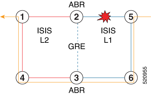
TI-LFA over GRE Tunnel as Protecting Interface

Supported

Supported

Additional Functionality
Maximum number of labels that can be pushed on the backup path (including the label of the protected prefix) 3 3
BFD-triggered Supported Supported
BFDv6-triggered Supported

N/A

Prefer backup path with lowest total metric

Supported

Supported

Prefer backup path from ECMP set Supported Supported
Prefer backup path from non-ECMP set Supported Supported
Load share prefixes across multiple backups paths

Supported

Supported

Limit backup computation up to the prefix priority Supported Supported
1 Unless specified, IS-IS support is IS-ISv4 and IS-ISv6

Configuring TI-LFA for IS-IS

This task describes how to enable per-prefix Topology Independent Loop-Free Alternate (TI-LFA) computation to converge traffic flows around link, node, and SRLG failures.

Before you begin

Ensure that the following topology requirements are met:

SUMMARY STEPS

  1. configure
  2. router isis instance-id
  3. interface type interface-path-id
  4. address-family ipv4 [ unicast]
  5. fast-reroute per-prefix
  6. fast-reroute per-prefix ti-lfa
  7. fast-reroute per-prefix tiebreaker { node-protecting | srlg-disjoint } index priority

DETAILED STEPS

  Command or Action Purpose

Step 1

configure

Example:


RP/0/RP0/CPU0:router# configure

Enters global configuration mode.

Step 2

router isis instance-id

Example:


RP/0/RP0/CPU0:router(config)# router isis 1

Enables IS-IS routing for the specified routing instance, and places the router in router configuration mode.

Note

 
You can change the level of routing to be performed by a particular routing instance by using the is-type router configuration command.

Step 3

interface type interface-path-id

Example:


RP/0/RP0/CPU0:router(config-isis)# interface GigabitEthernet0/0/2/1 

Enters interface configuration mode.

Step 4

address-family ipv4 [ unicast]

Example:


RP/0/RP0/CPU0:router(config-isis-if)# address-family ipv4 unicast 

Specifies the IPv4 address family, and enters router address family configuration mode.

Step 5

fast-reroute per-prefix

Example:


RP/0/RP0/CPU0:router(config-isis-if-af)# fast-reroute per-prefix

Enables per-prefix fast reroute.

Step 6

fast-reroute per-prefix ti-lfa

Example:


RP/0/RP0/CPU0:router(config-isis-if-af)# fast-reroute per-prefix ti-lfa

Enables per-prefix TI-LFA fast reroute link protection.

Step 7

fast-reroute per-prefix tiebreaker { node-protecting | srlg-disjoint } index priority

Example:


RP/0/RP0/CPU0:router(config-isis-if-af)# fast-reroute per-prefix tie-breaker srlg-disjoint index 100 

Enables TI-LFA node or SRLG protection and specifies the tiebreaker priority. Valid priority values are from 1 to 255. The lower the priority value, the higher the priority of the rule. Link protection always has a lower priority than node or SRLG protection.

Note

 
The same attribute cannot be configured more than once on an interface.

Note

 
For IS-IS, TI-LFA node protection and SRLG protection can be configured on the interface or the instance.

TI-LFA has been successfully configured for segment routing.

Configuring TI-LFA for OSPF

This task describes how to enable per-prefix Topology Independent Loop-Free Alternate (TI-LFA) computation to converge traffic flows around link, node, and SRLG failures.


Note


TI-LFA can be configured on the instance, area, or interface. When configured on the instance or area, all interfaces in the instance or area inherit the configuration.

Before you begin

Ensure that the following topology requirements are met:

SUMMARY STEPS

  1. configure
  2. router ospf process-name
  3. area area-id
  4. interface type interface-path-id
  5. fast-reroute per-prefix
  6. fast-reroute per-prefix ti-lfa
  7. fast-reroute per-prefix tiebreaker { node-protecting | srlg-disjoint } index priority

DETAILED STEPS

  Command or Action Purpose

Step 1

configure

Example:


RP/0/RP0/CPU0:router# configure

Enters global configuration mode.

Step 2

router ospf process-name

Example:


RP/0/RP0/CPU0:router(config)# router ospf 1

Enables OSPF routing for the specified routing process, and places the router in router configuration mode.

Step 3

area area-id

Example:


RP/0/RP0/CPU0:router(config-ospf)# area 1

Enters area configuration mode.

Step 4

interface type interface-path-id

Example:


RP/0/RP0/CPU0:router(config-ospf-ar)# interface GigabitEthernet0/0/2/1 

Enters interface configuration mode.

Step 5

fast-reroute per-prefix

Example:


RP/0/RP0/CPU0:router(config-ospf-ar-if)# fast-reroute per-prefix 

Enables per-prefix fast reroute.

Step 6

fast-reroute per-prefix ti-lfa

Example:


RP/0/RP0/CPU0:router(config-ospf-ar-if)# fast-reroute per-prefix ti-lfa 

Enables per-prefix TI-LFA fast reroute link protection.

Step 7

fast-reroute per-prefix tiebreaker { node-protecting | srlg-disjoint } index priority

Example:


RP/0/RP0/CPU0:router(config-ospf-ar-if)# fast-reroute per-prefix tie-breaker srlg-disjoint index 100 

Enables TI-LFA node or SRLG protection and specifies the tiebreaker priority. Valid priority values are from 1 to 255. The higher the priority value, the higher the priority of the rule. Link protection always has a lower priority than node or SRLG protection.

Note

 
The same attribute cannot be configured more than once on an interface.

TI-LFA has been successfully configured for segment routing.

TI-LFA Node and SRLG Protection: Examples

The following examples show the configuration of the tiebreaker priority for TI-LFA node and SRLG protection, and the behavior of post-convergence backup-path. These examples use OSPF, but the same configuration and behavior applies to IS-IS.

Example: Enable link-protecting and node-protecting TI-LFA


router ospf 1
 area 1
  interface GigabitEthernet0/0/2/1
    fast-reroute per-prefix 
    fast-reroute per-prefix ti-lfa
    fast-reroute per-prefix tiebreaker node-protecting index 100

Both link-protecting and node-protecting TI-LFA backup paths will be computed. If the priority associated with the node-protecting tiebreaker is higher than any other tiebreakers, then node-protecting post-convergence backup paths will be selected, if it is available.

Example: Enable link-protecting and SRLG-protecting TI-LFA


router ospf 1
 area 1
  interface GigabitEthernet0/0/2/1
    fast-reroute per-prefix 
    fast-reroute per-prefix ti-lfa
    fast-reroute per-prefix tiebreaker srlg-disjoint index 100

Both link-protecting and SRLG-protecting TI-LFA backup paths will be computed. If the priority associated with the SRLG-protecting tiebreaker is higher than any other tiebreakers, then SRLG-protecting post-convergence backup paths will be selected, if it is available.

Example: Enable link-protecting, node-protecting and SRLG-protecting TI-LFA


router ospf 1
 area 1
  interface GigabitEthernet0/0/2/1
    fast-reroute per-prefix 
    fast-reroute per-prefix ti-lfa
    fast-reroute per-prefix tiebreaker node-protecting index 200
    fast-reroute per-prefix tiebreaker srlg-disjoint index 100

Link-protecting, node-protecting, and SRLG-protecting TI-LFA backup paths will be computed. If the priority associated with the node-protecting tiebreaker is highest from all tiebreakers, then node-protecting post-convergence backup paths will be selected, if it is available. If the node-protecting backup path is not available, SRLG-protecting post-convergence backup path will be used, if it is available.

Configuring Global Weighted SRLG Protection

A shared risk link group (SRLG) is a set of links sharing a common resource and thus shares the same risk of failure. The existing loop-free alternate (LFA) implementations in interior gateway protocols (IGPs) support SRLG protection. However, the existing implementation considers only the directly connected links while computing the backup path. Hence, SRLG protection may fail if a link that is not directly connected but shares the same SRLG is included while computing the backup path. Global weighted SRLG protection feature provides better path selection for the SRLG by associating a weight with the SRLG value and using the weights of the SRLG values while computing the backup path.

To support global weighted SRLG protection, you need information about SRLGs on all links in the area topology. For IS-IS, you can flood SRLGs for remote links or manually configuring SRLGs on remote links. For OSPF, the SRLG values are advertised in the Extended Link LSA when SRLG is configured for that interface and Segment Routing is enabled.

The administrative weight (cost) of the SRLG can be configured using the admin-weight command. This command can be applied for all SRLG (global), or for a specific (named) SRLG. The default (global) admin-weight value is 1 for IS-IS, and 1000 for OSPF.

Configuration Examples: Global Weighted SRLG Protection for IS-IS

There are three types of configurations that are supported for the global weighted SRLG protection feature for IS-IS:

  • Local SRLG with global weighted SRLG protection

  • Remote SRLG flooding

  • Remote SRLG static provisioning

This example shows how to configure the local SRLG with global weighted SRLG protection feature.

RP/0/RP0/CPU0:router(config)# srlg
RP/0/RP0/CPU0:router(config-srlg)# interface TenGigE0/0/0/0
RP/0/RP0/CPU0:router(config-srlg-if)# name group1
RP/0/RP0/CPU0:router(config-srlg-if)# exit
RP/0/RP0/CPU0:router(config-srlg)# interface TenGigE0/0/0/1
RP/0/RP0/CPU0:router(config-srlg-if)# name group1
RP/0/RP0/CPU0:router(config-srlg)# exit
RP/0/RP0/CPU0:router(config-srlg)# name group1 value 100
RP/0/RP0/CPU0:router(config-srlg)# exit
RP/0/RP0/CPU0:router(config)# router isis 1 
RP/0/RP0/CPU0:router(config-isis)# address-family ipv4 unicast
RP/0/RP0/CPU0:router(config-isis-af)# fast-reroute per-prefix srlg-protection weighted-global
RP/0/RP0/CPU0:router(config-isis-af)# fast-reroute per-prefix tiebreaker srlg-disjoint index 1
RP/0/RP0/CPU0:router(config-isis-af)# exit
RP/0/RP0/CPU0:router(config-isis)# interface TenGigE0/0/0/0
RP/0/RP0/CPU0:router(config-isis-if)# point-to-point 
RP/0/RP0/CPU0:router(config-isis-if)# address-family ipv4 unicast
RP/0/RP0/CPU0:router(config-isis-if-af)# fast-reroute per-prefix 
RP/0/RP0/CPU0:router(config-isis-if-af)# fast-reroute per-prefix ti-lfa
RP/0/RP0/CPU0:router(config-isis-if-af)# exit
RP/0/RP0/CPU0:router(config-isis-if)# exit
RP/0/RP0/CPU0:router(config-isis)# srlg
RP/0/RP0/CPU0:router(config-isis-srlg)# name group1 
RP/0/RP0/CPU0:router(config-isis-srlg-name)# admin-weight 5000

This example shows how to configure the global weighted SRLG protection feature with remote SRLG flooding. The configuration includes local and remote router configuration. On the local router, the global weighted SRLG protection is enabled by using the fast-reroute per-prefix srlg-protection weighted-global command. In the remote router configuration, you can control the SRLG value flooding by using the advertise application lfa link-attributes srlg command. You should also globally configure SRLG on the remote router.

The local router configuration for global weighted SRLG protection with remote SRLG flooding is as follows:

RP/0/RP0/CPU0:router(config)# router isis 1 
RP/0/RP0/CPU0:router(config-isis)# address-family ipv4 unicast
RP/0/RP0/CPU0:router(config-isis-af)# fast-reroute per-prefix srlg-protection weighted-global
RP/0/RP0/CPU0:router(config-isis-af)# fast-reroute per-prefix tiebreaker srlg-disjoint index 1
RP/0/RP0/CPU0:router(config-isis-af)# exit
RP/0/RP0/CPU0:router(config-isis)# interface TenGigE0/0/0/0
RP/0/RP0/CPU0:router(config-isis-if)# point-to-point 
RP/0/RP0/CPU0:router(config-isis-if)# address-family ipv4 unicast
RP/0/RP0/CPU0:router(config-isis-if-af)# fast-reroute per-prefix 
RP/0/RP0/CPU0:router(config-isis-if-af)# fast-reroute per-prefix ti-lfa
RP/0/RP0/CPU0:router(config-isis-if-af)# exit
RP/0/RP0/CPU0:router(config-isis-if)# exit
RP/0/RP0/CPU0:router(config-isis)# srlg
RP/0/RP0/CPU0:router(config-isis-srlg)# name group1 
RP/0/RP0/CPU0:router(config-isis-srlg-name)# admin-weight 5000

The remote router configuration for global weighted SRLG protection with remote SRLG flooding is as follows:

RP/0/RP0/CPU0:router(config)# srlg
RP/0/RP0/CPU0:router(config-srlg)# interface TenGigE0/0/0/0
RP/0/RP0/CPU0:router(config-srlg-if)# name group1
RP/0/RP0/CPU0:router(config-srlg-if)# exit
RP/0/RP0/CPU0:router(config-srlg)# interface TenGigE0/0/0/1
RP/0/RP0/CPU0:router(config-srlg-if)# name group1
RP/0/RP0/CPU0:router(config-srlg-if)# exit
RP/0/RP0/CPU0:router(config-srlg)# name group1 value 100
RP/0/RP0/CPU0:router(config-srlg)# exit
RP/0/RP0/CPU0:router(config)# router isis 1
RP/0/RP0/CPU0:router(config-isis)# address-family ipv4 unicast
RP/0/RP0/CPU0:router(config-isis-af)# advertise application lfa link-attributes srlg

This example shows configuring the global weighted SRLG protection feature with static provisioning of SRLG values for remote links. You should perform these configurations on the local router.


RP/0/RP0/CPU0:router(config)# srlg
RP/0/RP0/CPU0:router(config-srlg)# interface TenGigE0/0/0/0
RP/0/RP0/CPU0:router(config-srlg-if)# name group1
RP/0/RP0/CPU0:router(config-srlg-if)# exit
RP/0/RP0/CPU0:router(config-srlg)# interface TenGigE0/0/0/1
RP/0/RP0/CPU0:router(config-srlg-if)# name group1
RP/0/RP0/CPU0:router(config-srlg-if)# exit
RP/0/RP0/CPU0:router(config-srlg)# name group1 value 100
RP/0/RP0/CPU0:router(config-srlg)# exit
RP/0/RP0/CPU0:router(config)# router isis 1
RP/0/RP0/CPU0:router(config-isis)# address-family ipv4 unicast
RP/0/RP0/CPU0:router(config-isis-af)# fast-reroute per-prefix srlg-protection weighted-global
RP/0/RP0/CPU0:router(config-isis-af)# fast-reroute per-prefix tiebreaker srlg-disjoint index 1
RP/0/RP0/CPU0:router(config-isis-af)# exit
RP/0/RP0/CPU0:router(config-isis)# interface TenGigE0/0/0/0
RP/0/RP0/CPU0:router(config-isis-if)# point-to-point 
RP/0/RP0/CPU0:router(config-isis-if)# address-family ipv4 unicast
RP/0/RP0/CPU0:router(config-isis-if-af)# fast-reroute per-prefix 
RP/0/RP0/CPU0:router(config-isis-if-af)# fast-reroute per-prefix ti-lfa
RP/0/RP0/CPU0:router(config-isis-if-af)# exit
RP/0/RP0/CPU0:router(config-isis-if)# exit
RP/0/RP0/CPU0:router(config-isis)# srlg
RP/0/RP0/CPU0:router(config-isis-srlg)# name group1 
RP/0/RP0/CPU0:router(config-isis-srlg-name)# admin-weight 5000
RP/0/RP0/CPU0:router(config-isis-srlg-name)# static ipv4 address 10.0.4.1 next-hop ipv4 address 10.0.4.2
RP/0/RP0/CPU0:router(config-isis-srlg-name)# static ipv4 address 10.0.4.2 next-hop ipv4 address 10.0.4.1

Configuration Examples: Global Weighted SRLG Protection for OSPF

There are two types of configurations that are supported for the global weighted SRLG protection feature for OSPF:

  • Local SRLG with global weighted SRLG protection

  • Remote SRLG static provisioning


Note


There is no specific configuration to enable SRLG flooding in OSPF. The SRLG values are advertised in the Extended Link LSA if SRLG is configured for that interface and Segment Routing is enabled.

This example shows how to configure the local SRLG with global weighted SRLG protection feature.

Router(config)# srlg
Router(config-srlg)# interface hundredGigE 0/0/0/0
Router(config-srlg-if)# name group1
Router(config-srlg-if)# exit
Router(config-srlg)# interface hundredGigE 0/0/0/1
Router(config-srlg-if)# name group1
Router(config-srlg-if)# exit
Router(config-srlg)# name group1 value 100
Router(config-srlg)# exit
Router(config)# router ospf 1
Router(config-ospf)# fast-reroute per-prefix srlg-protection weighted-global
Router(config-ospf)# fast-reroute per-prefix tiebreaker srlg-disjoint index 1
Router(config-ospf-ar)# interface hundredGigE 0/0/0/0
Router(config-ospf-ar-if)# fast-reroute per-prefix
Router(config-ospf-ar-if)# fast-reroute per-prefix ti-lfa
Router(config-ospf-ar-if)# exit
Router(config-ospf-ar)# exit
Router(config-ospf)# srlg
Router(config-ospf-srlg)# admin-weight 3000
Router(config-ospf-srlg)# name group1
Router(config-ospf-srlg-name)# admin-weight 5000

This example shows configuring the global weighted SRLG protection feature with static provisioning of SRLG values for remote links. You should perform these configurations on the remote router.

Router(config)# srlg
Router(config-srlg)# interface hundredGigE 0/0/0/0
Router(config-srlg-if)# name group1
Router(config-srlg-if)# exit
Router(config-srlg)# interface hundredGigE 0/0/0/1
Router(config-srlg-if)# name group1
Router(config-srlg-if)# exit
Router(config-srlg)# name group1 value 100
Router(config-srlg)# exit
Router(config)# router ospf 1
Router(config-ospf)# area 1
Router(config-ospf-ar)# interface hundredGigE 0/0/0/0
Router(config-ospf-ar-if)# exit
Router(config-ospf-ar)# exit

SR-MPLS over GRE as TI-LFA Backup Path

This feature allows the router (as ABR) to program a Generic Routing Encapsulation (GRE) tunnel as an outgoing interface for TI-LFA backup paths computed by the IGP in a Segment Routing network. Single-segment TI-LFA scenario is supported. In this scenario, the router pushes one extra label when programming the backup path.


Note


GRE is a tunneling protocol that provides a simple generic approach to transport packets of one protocol over another protocol by means of encapsulation. See the Configuring GRE Tunnels chapter in the Interface and Hardware Component Configuration Guide for Cisco NCS 5500 Series Routers.

Multi-Level Network Topology

The following example shows a multi-level network topology with interconnecting links between ABRs.


Note


This could also be a multi-instance network topology.

Two links between ABR 2 and ABR 3 are required, one in each IS-IS level. These links provide protection in each direction and ensure that there is always an alternate path inside the IGP domain.


Note


Alternatively, a single link with two logical sub-interfaces could be used between the ABRs.

TI-LFA performs the backup path calculation inside the domain (process, level, or area) of the failed link.

For example, if the link between nodes 2 and 5 failed, the link between ABR 2 and 3 would create a TI-LFA path in L1 IS-IS level. If the link between nodes 1 and 2 failed, the link between ABR 2 and 3 would create a TI-LFA path in L2 IS-IS level.

However, if the interconnecting link between ABRs are in the same Shared Risk Link Groups (SRLG) as other links inside the domain (for example, the link between Nodes 2 and 3 are in the same SRLG as link between Nodes 2 and 5), TI-LFA with local SRLG protection would not find an alternate path.

In cases where it is not feasible to provide interconnecting links between ABRs (for example, the ABR nodes might be in different locations with no connectivity options), TI-LFA will not be able to compute backup paths for all of the prefixes.

To address these issues, you can create a GRE tunnel in each domain, between the ABRs, which can be used as TI-LFA backup paths.

Now, if a link failure occurs in either IS-IS level (for example, between nodes 1 and 2 or between nodes 2 and 5), the path is protected by the GRE tunnel.

Backup Path for Link Failure Between Nodes 2 and 5

Traffic from node 1 is rerouted over the GRE tunnel TI-LFA backup path between ABR nodes 2 and 3.

Traffic flowing in the opposite direction, from node 5 to node 1, is simply routed over nodes 6-3-4 to node 1.

Limitations

The following behaviors and limitations apply to the router when a GRE tunnel is programmed as backup interface for TI-LFA:

  • The MPLS label of a protected prefix must be the same in the primary and backup paths (SWAP scenario)

  • Single-segment TI-LFA is supported. In this scenario, the router pushes one extra label when programming the backup path. The total label stack is 2, including the primary label and backup label.

  • Double-segment (or more) TI-LFA is not supported. In this scenario, the router pushes two or more extra labels when programming the backup path.

  • GRE tunnel as a primary or backup path for an SR policy with TI-LFA protection is not supported.

Example: SR-MPLS over GRE as TI-LFA Backup Path

The examples in this section use the following network topology:

Configurations Without Interconnecting ABR Links

The following sample configurations show OSPF configurations for nodes 2, 3 and 5. Nodes 2 and 3 are ABRs between Area 0 and Area 100. There is no connection between the ABRs.

Configuration on ABR 2 for Area 0 and Area 100

router ospf 100
 router-id 2.2.2.2
 segment-routing mpls
 segment-routing forwarding mpls
 fast-reroute per-prefix
 fast-reroute per-prefix ti-lfa enable
 segment-routing sr-prefer
 area 0
  interface Loopback0
   prefix-sid index 2
  !
 !
  interface TenGigE0/0/1/10
   network point-to-point
  !
 !
 area 100
  interface TenGigE0/0/1/11
    network point-to-point

RP/0/RSP0/CPU0:ABR2# show ospf neighbor area-sorted 
Fri Jul 19 09:43:59.328 UTC

Neighbors for OSPF 100
Area 0

Neighbor ID     Pri State    Dead Time Address         Up Time  Interface
10.1.1.1        1   FULL/  - 00:00:35  10.1.2.1        1d20h    Te0/0/1/10

Total neighbor count: 1

Area 100

Neighbor ID     Pri State    Dead Time Address         Up Time  Interface
5.5.5.5         1   FULL/  - 00:00:33  10.2.5.5        1d20h    Te0/0/1/11

Total neighbor count: 1

Configuration on ABR 3 for Area 0 and Area 100

router ospf 100
 router-id 3.3.3.3
 segment-routing mpls
 segment-routing forwarding mpls
 fast-reroute per-prefix
 fast-reroute per-prefix ti-lfa enable
 segment-routing sr-prefer
 area 0
   interface Loopback0
   prefix-sid index 3
  !
  interface TenGigE0/0/0/9
  network point-to-point
  !
 !
 area 100
  interface TenGigE0/0/0/3
  network point-to-point
 !
RP/0/RSP0/CPU0:ABR3# show ospf neighbor area-sorted
Fri Jul 19 09:33:35.816 UTC

Neighbors for OSPF 100
Area 0

Neighbor ID     Pri State    Dead Time Address         Up Time  Interface
4.4.4.4         1   FULL/  - 00:00:36  10.3.4.4        2d17h    Te0/0/0/9

Total neighbor count: 1

Area 100

Neighbor ID     Pri State    Dead Time Address         Up Time  Interface
6.6.6.6         1   FULL/  - 00:00:36  10.3.6.6        2d19h    Te0/0/0/3

Total neighbor count: 1

Configuration on Node 5

segment-routing mpls
 !
 set-attributes
  address-family ipv4
   sr-label-preferred
 !        
 connected-prefix-sid-map
  address-family ipv4
   5.5.5.5/32 index 5 range 1 
 !
interface TenGigabitEthernet0/0/26
 description ***Connected to ABR 2
 ip address 10.2.5.5 255.255.255.0
 ip ospf network point-to-point
 cdp enable 
!
interface TenGigabitEthernet0/0/27
 description ***Connected to Node 6 
 ip address 10.5.6.5 255.255.255.0
 ip ospf network point-to-point
 cdp enable

router ospf 100
 router-id 5.5.5.5
 segment-routing area 100 mpls
 segment-routing mpls
 fast-reroute per-prefix enable prefix-priority low
 fast-reroute per-prefix ti-lfa
 fast-reroute per-prefix ti-lfa area 100 
 passive-interface default
 no passive-interface TenGigabitEthernet0/0/26
 no passive-interface TenGigabitEthernet0/0/27
 network 10.2.5.0 0.0.0.255 area 100
 network 10.5.5.0 0.0.0.255 area 100
 network 10.5.6.0 0.0.0.255 area 100
 network 5.5.5.5 0.0.0.0 area 100

RP/0/RSP0/CPU0:Node5# show ip ospf neighbor 
Load for five secs: 4%/1%; one minute: 4%; five minutes: 4%
Time source is NTP, 09:50:51.417 UTC Fri Jul 19 2019

Neighbor ID   Pri   State      Dead Time   Address         Interface
6.6.6.6         0   FULL/  -   00:00:32    10.5.6.6        TenGigabitEthernet0/0/27
2.2.2.2         0   FULL/  -   00:00:36    10.5.2.5        TenGigabitEthernet0/0/26

TI-LFA Fast Reroute Coverage on Node 5

The following output shows that this configuration provides only 52% TI-LFA fast reroute coverage on Node 5:

RP/0/RSP0/CPU0:Node5# show ip ospf fast-reroute prefix-summary 
Load for five secs: 4%/1%; one minute: 4%; five minutes: 4%
Time source is NTP, 10:32:20.236 UTC Fri Jul 19 2019
            OSPF Router with ID (5.5.5.5) (Process ID 100)
                    Base Topology (MTID 0)
Area 100:
Interface        Protected    Primary paths    Protected paths Percent protected
                             All  High   Low   All  High   Low    All High  Low
Lo0                    Yes     0     0     0     0     0     0     0%   0%   0%
Te0/0/27               Yes     7     4     3     1     1     0    14%  25%   0%
Te0/0/26               Yes    10     5     5     8     4     4    80%  80%  80%

Area total:                   17     9     8     9     5     4    52%  55%  50%

Process total:                17     9     8     9     5     4    52%  55%  50%

GRE Tunnel Configuration

The following examples show how to configure GRE tunnels between the ABRs in each area to provide TI-LFA backup paths for the Segment Routing network.

GRE BLU is configured in Area 0 using Loopback50 (on ABR2) and Loopback 60 (on ABR 3). These loopbacks are advertised in Area 100:

Figure 3. GRE BLU

GRE RED is configured in Area 100 using Loopback55 (on ABR2) and Loopback 66 (on ABR3). These loopbacks are advertised in Area 0:

Figure 4. GRE RED

Configuration on ABR 2

interface Loopback0
 ipv4 address 2.2.2.2 255.255.255.255
!
interface Loopback50
 description Lo for GRE BLU
 ipv4 address 50.0.0.50 255.255.255.0
!
interface Loopback55
 description Lo for GRE RED
 ipv4 address 55.55.55.55 255.255.255.255
!
interface tunnel-ip5060
 description GRE virtual link for Area 0 BLU
 ipv4 address 66.3.2.2 255.255.255.0
 tunnel source Loopback50
 tunnel destination 60.0.0.60
!
interface tunnel-ip5566
 description GRE virtual link for Area 100 RED
 ipv4 address 100.3.2.2 255.255.255.0
 tunnel source Loopback55
 tunnel destination 66.66.66.66

router ospf 100
 router-id 2.2.2.2
 segment-routing mpls
 segment-routing forwarding mpls
 fast-reroute per-prefix
 fast-reroute per-prefix ti-lfa enable
 segment-routing sr-prefer
 area 0
  interface Loopback0
   prefix-sid index 2
  !
  interface Loopback55
   passive enable
  !
  interface tunnel-ip5060
   cost 1000
 !
  interface TenGigE0/0/1/10
   network point-to-point
  !
 !
 area 100
  interface Loopback50
   passive enable
  !
  interface tunnel-ip5566
   cost 1000
  !
  interface TenGigE0/0/1/11
    network point-to-point

Note


In the above configuration, GRE tunnel-ip5060 belongs to area 0, but its source and destination addresses are advertised in area 100. This ensures disjointness between the GRE tunnel and the links in area 0 that it protects. The same applies to GRE tunnel-ip5566 which belongs to area 100 and its source and destination addresses are advertised in area 0.

A high cost is applied to the GRE tunnel interfaces so that they are used only as a backup path.


Configuration on ABR 3

interface Loopback0
 ipv4 address 3.3.3.3 255.255.255.255
!
interface Loopback60
 description Lo for GRE BLU
 ipv4 address 60.0.0.60 255.255.255.0
!
interface Loopback66
 description Lo for GRE RED
 ipv4 address 66.66.66.66 255.255.255.255
!
interface tunnel-ip5060
 description GRE virtual link for Area 0 BLU
 ipv4 address 66.3.2.3 255.255.255.0
 tunnel source Loopback60
 tunnel destination 50.0.0.50
!
interface tunnel-ip5566
 description GRE virtual link for Area 100 RED
 ipv4 address 100.3.2.3 255.255.255.0
 tunnel source Loopback66
 tunnel destination 55.55.55.55

router ospf 100
 router-id 3.3.3.3
 segment-routing mpls
 segment-routing forwarding mpls
 fast-reroute per-prefix
 fast-reroute per-prefix ti-lfa enable
 segment-routing sr-prefer
 area 0
   interface Loopback0
   prefix-sid index 3
  !
  interface TenGigE0/0/0/9
  network point-to-point
  !
  interface Loopback66
   passive enable
  !
  interface tunnel-ip5060
   cost 1000
 !
 area 100
  interface TenGigE0/0/0/3
  network point-to-point
 !
  interface Loopback60
   passive enable
  !
  interface tunnel-ip5566
   cost 1000


Note


In the above configuration, GRE tunnel-ip5060 belongs to area 0, but its source and destination addresses are advertised in area 100. This ensures disjointness between the GRE tunnel and the links in area 0 that it protects. The same applies to GRE tunnel-ip5566 which belongs to area 100 and its source and destination addresses are advertised in area 0.

A high cost is applied to the GRE tunnel interfaces so that they are used only as a backup path.


TI-LFA Fast Reroute Coverage on Node 5 After GRE Tunnel Configuration

The following output shows that this configuration provides 100% TI-LFA fast reroute coverage on Node 5:

RP/0/RSP0/CPU0:Node5# show ip ospf fast-reroute prefix-summary
Load for five secs: 5%/1%; one minute: 4%; five minutes: 4%
Time source is NTP, 11:20:31.743 UTC Fri Jul 19 2019
            OSPF Router with ID (5.5.5.5) (Process ID 100)
                    Base Topology (MTID 0)
Area 100:
Interface        Protected    Primary paths    Protected paths Percent protected
                             All  High   Low   All  High   Low    All High  Low
Lo0                    Yes     0     0     0     0     0     0     0%   0%   0%
Te0/0/27               Yes     9     6     3     9     6     3   100% 100% 100%
Te0/0/26               Yes    11     6     5    11     6     5   100% 100% 100%

Area total:                   20    12     8    20    12     8   100% 100% 100%

Process total:                20    12     8    20    12     8   100% 100% 100%

Traffic Flow with GRE Tunnel as TI-LFA Backup

With a link failure between Node 1 and ABR 2, traffic flowing from Node 1 to Node 5 is simply routed through Nodes 4-3-6 to Node 5.

With GRE tunnel as TI-LFA backup, traffic flowing from Node 5 to Node 1 will be encapsulated at ABR2 and routing over the GRE tunnel.

With a link failure between Node 5 and ABR 2, traffic flowing from Node 5 to Node 1 is simply routed through Nodes 6-3-4 to Node 1.

With GRE tunnel as TI-LFA backup, traffic flowing from Node 1 to Node 5 will be encapsulated at ABR2 and routing over the GRE tunnel.

Unlabeled IPv6 Traffic Protection

Table 2. Feature History Table

Feature Name

Release Information

Feature Description

IPv6 Unlabeled Traffic protection with TI-LFA

Release 7.3.1

TI-LFA provides protection for SR-labeled traffic (IPv4 and IPv6 prefixes associated with a prefix SID) and for other unlabeled IPv4 prefixes.

This feature introduces support for protecting unlabeled IPv6 prefixes.

This feature introduces support for protecting unlabeled IPv6 prefixes. IS-IS can calculate and install TI-LFA backup paths for unlabeled IPv6 prefixes.

By default, all IPv6 prefixes without a prefix SID are eligible to have a dynamic local label assigned to them. This behavior provides the greatest degree of protection, but in some deployments, it may consume too many MPLS labels. This feature provides the ability to disable local label allocation or to restrict local label allocation to a subset of prefixes based on a prefix list or route policy.

Use the following commands in IS-IS IPv6 address family configuration mode to specify the local label allocation behavior:

  • segment-routing mpls unlabeled protection disable—Disable local label allocation.

  • segment-routing mpls unlabeled protection prefix-list sample_prefix_list—Restricts local label allocation to the prefixes based on a prefix list.

  • segment-routing mpls unlabeled protection route-policy sample_rpl—Restricts local label allocation to the prefixes based a route policy.

Configuration

The following example shows how to disable local label allocation:

Router(config)# router isis 1
Router(config-isis)# address-family ipv6 unicast
Router(config-isis-af)# segment-routing mpls unlabeled protection disable
Router(config-isis-af)#

The following example shows how to enable local label allocation for prefixes in a prefix list:

Router(config)# ipv6 prefix-list sample_prefix_list
Router(config-ipv6-pfx)# 10 permit 333::333:0:0/96 ge 112
Router(config-ipv6-pfx)# 20 permit 666::666:0:0/96 ge 112
Router(config-ipv6-pfx)# exit
Router(config)#

Router(config)# router isis 1
Router(config-isis)# address-family ipv6 unicast
Router(config-isis-af)# segment-routing mpls unlabeled protection prefix-list sample_prefix_list
Router(config-isis-af)# commit

The following example shows how to enable local label allocation for prefixes in a route policy:

Router(config)# prefix-set sample_prefix_set
Router(config-pfx)# 333::333:1:0/112
Router(config-pfx)# end-set
Router(config)# route-policy sample_rpl
Router(config-rpl)# if destination in sample_prefix_set then
Router(config-rpl-if)# pass
Router(config-rpl-if)# else drop endif
Router(config-rpl)# end-policy
Router(config)#

Router(config)# router isis 1
Router(config-isis)# address-family ipv6 unicast
Router(config-isis-af)# segment-routing mpls unlabeled protection route-policy sample_rpl
Router(config-isis-af)# commit

Verification

In the following show command output, 24103 is the local label used to program the prefix with a TI-LFA backup.

Router# show isis ipv6 unicast route 333::333:1:0/112 detail
L2 333::333:1:0/112 [120/115] Label: 24103, low priority
     via fe80::28a:96ff:fef4:5403, TenGigE0/1/0/3/5, r6, SRGB Base: 16000, Weight: 0
     src R1.00-01, 1:1:1::1

Router# show isis ipv6 fast-reroute 333::333:1:0/112 detail
L2 333::333:1:0/112 [120/115] Label: 24103, low priority
     via fe80::28a:96ff:fef4:5403, TenGigE0/1/0/3/5, R6, SRGB Base: 16000, Weight: 0
       Backup path: TI-LFA (link), via fe80::2c1:64ff:fe60:39b9, TenGigE0/1/0/3/0 R4, SRGB Base: 16000, Weight: 0, Metric: 140
         P node: R3.00 [3:3:3::3], Label: 16333
         Prefix label: None
         Backup-src: R1.00
       P: No, TM: 140, LC: No, NP: No, D: No, SRLG: Yes
     src R1.00-a9, 1:1:1::1

Router# show route ipv6 333::333:1:0/112 detail
Routing entry for 333::333:1:0/112
  Known via "isis 1", distance 115, metric 120, type level-2
  Installed Jul 26 19:11:58.840 for 00:00:47
  Routing Descriptor Blocks
    fe80::2c1:64ff:fe60:39b9, from 1:1:1::1, via TenGigE0/1/0/3/0, Backup (TI-LFA)
      Repair Node(s): 3:3:3::3
      Route metric is 140
      Label: 0x3fcd (16333)
      Tunnel ID: None
      Binding Label: None
      Extended communities count: 0
      Path id:65              Path ref count:1
      NHID:0x20008(Ref:20026)
    fe80::28a:96ff:fef4:5403, from 1:1:1::1, via TenGigE0/1/0/3/5, Protected
      Route metric is 120
      Label: None
      Tunnel ID: None
      Binding Label: None
      Extended communities count: 0
      Path id:1       Path ref count:0
      NHID:0x20009(Ref:20021)
      Backup path id:65
  Route version is 0x1e (30)
  Local Label: 0x5e27 (24103)
  IP Precedence: Not Set
  QoS Group ID: Not Set
  Flow-tag: Not Set
  Fwd-class: Not Set
  Route Priority: RIB_PRIORITY_NON_RECURSIVE_LOW (8) SVD Type RIB_SVD_TYPE_LOCAL
  Download Priority 2, Download Version 4200135
  No advertising protos.

Router# show mpls forwarding labels 24103
Local  Outgoing    Prefix             Outgoing     Next Hop        Bytes       
Label  Label       or ID              Interface                    Switched    
------ ----------- ------------------ ------------ --------------- ------------
24103  Unlabelled  333::333:1:0/112   Te0/1/0/3/5  fe80::28a:96ff:fef4:5403   \
                                                                   0           
       16333       333::333:1:0/112   Te0/1/0/3/0  fe80::2c1:64ff:fe60:39b9   \
                                                                   0            (!)