Configure SRv6 Traffic Engineering

Table 1. Feature History Table

Feature Name

Release

Description

SRv6 Traffic Engineering

Release 7.3.2

This feature introduces Segment Routing over IPv6 (SRv6) Traffic Engineering.

This release supports the following features:

  • SRv6-TE with SRv6 micro-SIDs (uSIDs)

  • SRv6 policies

  • Manual SRv6 policies

  • Automated steering for Layer 3-based BGP services (IPv4 L3VPN, IPv6 L3VPN, IPv4 BGP global, IPv6 BGP global)

  • SRv6-aware Path Computation Element (PCE)

  • PCEPv6

  • Path computation optimization objectives (TE, IGP, latency)

  • Path computation constraints (affinity, disjointness)

This feature introduces Segment Routing over IPv6 (SRv6) Traffic Engineering.

SRv6-TE Overview

Traffic engineering over SRv6 can be accomplished in the following ways:

  • End-to-End Flexible Algorithm: This is used for traffic engineering intents achieved with Flexible Algorithm, including low latency, multi-plane disjointness, affinity inclusion/exclusion, and SRLG exclusion.

  • SRv6-TE Policy: This is used for traffic engineering intents beyond Flex Algo capabilities, such as path disjointness that rely on path computation by a PCE. In addition, this is used for user-configured explicit paths.

End-to-End Flexible Algorithm

SRv6 Flexible Algorithm allows operators to customize IGP shortest path computation according to their own needs. An operator can assign custom SRv6 locators to realize forwarding beyond link-cost-based shortest path. As a result, Flexible Algorithm provides a traffic-engineered path automatically computed by the IGP to any destination reachable by the IGP.

SRv6-TE Policy

SRv6 for traffic engineering (SRv6-TE) uses a “policy” to steer traffic through the network. An SRv6-TE policy path is expressed as a list of micro-segments that specifies the path, called a micro-segment ID (uSID) list. Each segment list is an end-to-end path from the source to the destination, and instructs the routers in the network to follow the specified path instead of following the shortest path calculated by the IGP. If a packet is steered into an SRv6-TE policy, the uSID list is pushed on the packet by the head-end. The rest of the network executes the instructions embedded in the uSID list.

An SRv6-TE policy is identified as an ordered list (head-end, color, end-point):

  • Head-end – Where the SRv6-TE policy is instantiated

  • Color – A numerical value that distinguishes between two or more policies to the same node pairs (Head-end – End point)

  • End-point – The destination of the SRv6-TE policy

Every SRv6-TE policy has a color value. Every policy between the same node pairs requires a unique color value.

An SRv6-TE policy uses one or more candidate paths. A candidate path can be made up of a single SID-list or a set of weighted SID-lists (for weighted equal cost multi-path [WECMP]).

A SID list can be either the result of a dynamic path computation by a PCE or a user-configured explicit path. See SRv6-TE Policy Path Types for more information.

Usage Guidelines and Limitations

Table 2. Feature History Table

Feature Name

Release

Description

Cisco NC57 Native Mode: Automated Steering of L3 BGP-based services

Release 7.8.1

This feature is now supported on routers that have the Cisco NC57 line cards installed and operate in the native mode.

To enable the native mode, use the hw-module profile npu native-mode-enable command in the configuration mode. Ensure that you reload the router after configuring the native mode.

Observe the following usage guidelines and limitations for the platform.

This release supports the following SRv6 policy functionality:

  • SRv6 policies with SRv6 uSID segments

  • SRv6 policies with PCE-delegated dynamic paths

  • SRv6 policies with explicit paths

  • SRv6 policies with single or multiple candidate paths (CP)

  • SRv6 policies with a single SID list per CP

  • SRv6 policies with multiple (weighted ECMP) SID lists per CP

  • Path delegation and reporting with PCEPv4

  • Path delegation and reporting with PCEPv6

  • PCEPv4 and PCEPv6 sessions with different PCEs

  • PCEP path delegation with the following optimization objective (metric) types:

    • IGP metric

    • TE metric

    • Delay (latency)

    • Hop-count

  • PCEP path delegation with the following constraint types:

    • Affinity (include-any, include-all, exclude-any)

    • Path disjointness (link, node, SRLG, SRLG+node)

    • Segment protection-type:

      • Protected-only

      • Protected-preferred

      • Unprotected-only

      • Unprotected-preferred

  • SRv6 policy with TI-LFA (protection of the first segment in the segment list at the head-end)

  • Steering over SRv6 policies with Automated Steering for the following services:

    • L3 BGP-based services (IPv4 L3VPN, IPv6 L3VPN, IPv4 BGP global, IPv6 BGP global)

    • L2 BGP-based service (EVPN VPWS)

The following functionalities are not supported:

  • SRv6 policy counters

  • PCE-initiated SRv6 policies via PCEP

  • SRv6 policies with head-end computed dynamic paths

  • PCE path delegation with segment-type Flex Algo constraint

  • PCEPv4 and PCEPv6 sessions with same PCE

  • Steering over SRv6 policies based on incoming BSID (remote automated steering)

  • PCC with user-configured PCE groups

  • SR-PM delay-measurement over SRv6 policies

  • SR-PM liveness detection over SRv6 policies

  • L3 services with BGP PIC over SRv6 policies

  • SRv6 policy ping

SR-PCE and SRv6-TE head-end PCEP compatibility:

  • A PCEP session between an SR-PCE running Cisco IOS XR release 7.8.1 and an SRv6-TE head-end running Cisco IOS XR release 7.8.1 is supported.

  • A PCEP session between an SR-PCE running Cisco IOS XR release 7.8.1 and an SRv6-TE head-end running an earlier release is supported.

  • A PCEP session between an SR-PCE running Cisco IOS XR release earlier than 7.8.1 and an SRv6-TE head-end running Cisco IOS XR release 7.8.1 is not supported.

  • A PCEP session between an SR-PCE running Cisco IOS XR release 7.8.1 and another SR-PCE running an earlier Cisco IOS XR release is not supported.

  • As a result of the above, prior to upgrading any SRv6-TE headend nodes in the network to Cisco IOS XR release 7.8.1, you must upgrade its SR-PCE to Cisco IOS XR release 7.8.1.


    Note


    When a pair of SR-PCEs part of the same redundancy group run different versions of Cisco IOS XR, they will lose their state-sync PCEP session until both SR-PCEs are upgraded to Cisco IOS XR release 7.8.1.

Traffic Steering

SRv6 Flexible Algorithm

With SRv6 Flexible Algorithm, a PE can advertise BGP service routes (global, VPN) that include the SRv6 locator (Algo 0 or Flex Algo) of the intended transport SLA.

For information about configuring Flexible Algorithm, see Configuring SRv6 IS-IS Flexible Algorithm.

In the example below, the SR domain has 2 network slices. Each slice is assigned a /32 uSID Locator Block.

A slice can be realized with a user-defined Flex-Algo instances (for example, Flex Algo 128 = min-delay)

  • Min-Cost Slice — FCBB:BB00/32

  • Min-Delay Slice — FCBB:BB01/32

SR node2 gets a Shortest-Path Endpoint uSID (uN) from each slice:

  • uN min-cost of Node2 — FCBB:BB00:0002/48

  • uN min-delay of Node2 — FCBB:BB01:0002/48

Node2 announces locators via IS-IS:

  • FCBB:BB00:0002/48 Algo 0 (min-cost)

  • FCBB:BB01:0002/48 Algo 128 (min-delay)


IS-IS in Node1 computes shortest paths for each locator and programs them in the FIB:


Node1 and Node2 are PEs of a common VPN. PEs advertise VPN routes via BGP with different transport SLAs. For example, traffic to a set of prefixes is to be delivered over the min-cost slice, while for another set of prefixes is to be delivered over the min-delay slice. To achieve this, the egress PE’s service route advertisement includes the locator of the intended transport SLA type.

Use-case: VPN over Min-Cost Slice (Control Plane Behavior)

  • Intuitive uSID program for routes advertised by Node2:

    • Within the Min-Cost Slice (FCBB:BB00)

    • Follow the shortest-path to Node2 (0002)

    • Execute VPN9 decapsulation function at Node2 (F009)

  • Hardware Efficiency

    • Egress PE Node2 processes multiple uSIDs with a single /64 lookup

    • FCBB:BB00:0002:F009/64

Use-case: VPN over Min-Delay Slice (Control Plane Behavior)

  • Intuitive uSID program for routes advertised by Node2:

    • Within the Min-Delay Slice (FCBB:BB01)

    • Follow the shortest-path to Node2 (0002)

    • Execute VPN9 decapsulation at Node2 (F009)

  • Hardware Efficiency

    • Egress PE 2 processes multiple uSIDs with a single /64 lookup

    • FCBB:BB01:0002:F009/64

Use-case: VPN over Min-Cost Slice (Data Plane Behavior)

  1. Ingress PE (Node 1) learns via BGP that prefix 10.2.0.0/24 in VPN9 is reachable via SID FCBB:BB00:0002:F009

  2. Node 1 programs the prefix with “VPN Encaps” behavior

  3. When receiving traffic with DA IP matching the prefix 10.2.0.0/24 FIB entry, Node 1 encapsulates the incoming packet into IPv6 with DA of FCBB:BB00:0002:F009


  4. SRv6 allows for seamless deployment where any transit node (SRv6-capable or not) simply routes based on a /48 longest prefix match lookup.

    For example, transit node (Node 3) forwards traffic along the Algo 0 (min-cost) shortest path for the remote prefix FCBB:BB00:0002::/48.


  5. Egress PE (Node 2) matches local SID FCBB:BB00:0002:F009/64. Node 2 applies “VPN Decaps” behavior into VRF9 by removing the IPv6 encapsulation and looking up the payload’s DA on the corresponding VPN table.


Use-case: VPN over Min-Delay Slice (Data Plane Behavior)

  1. Ingress PE (Node 1) learns via BGP that prefix 20.2.0.0/24 in VPN9 is reachable via SID FCBB:BB01:0002:F009

  2. Node 1 programs the prefix with “VPN Encaps” behavior

  3. When receiving traffic with DA IP matching the prefix 20.2.0.0/24 FIB entry, Node 1 encapsulates the incoming packet into IPv6 with DA of FCBB:BB01:0002:F009

  4. Transit node (Node 3) forwards traffic along the Algo 128 (min-delay) shortest path for the remote prefix FCBB:BB01:0002::/48.

  5. Egress PE (Node 2) matches local SID FCBB:BB01:0002:F009/64. Node 2 applies “VPN Decaps” behavior into VRF9 by removing the IPv6 encapsulation and looking up the payload’s DA on the corresponding VPN table.

Automated Steering

Automated steering (AS) allows service traffic to be automatically steered onto the required transport SLA path programmed by an SRv6 policy.

With AS, BGP automatically steers traffic onto an SRv6 policy based on the next-hop and color of a BGP service route. The color of a BGP service route is specified by a color extended community attribute. This color is used as a transport SLA indicator, such as min-delay or min-cost.

When the next-hop and color of a BGP service route matches the end-point and color of an SRv6 policy, BGP automatically installs the route resolving onto the BSID of the matching SRv6 policy. Recall that an SRv6 policy on a head-end is uniquely identified by an end-point and color.

When a BGP route has multiple extended-color communities, each with a valid SRv6 policy, the BGP process installs the route on the SRv6 policy giving preference to the color with the highest numerical value.

The granularity of AS behaviors can be applied at multiple levels, for example:

  • At a service level—When traffic destined to all prefixes in a given service is associated to the same transport path type. All prefixes share the same color.

  • At a destination/prefix level—When traffic destined to a prefix in a given service is associated to a specific transport path type. Each prefix could be assigned a different color.

  • At a flow level—When flows destined to the same prefix are associated with different transport path types

SRv6-TE Policy Path Types

An explicit path is a specified SID-list or set of SID-lists.

A dynamic path is based on an optimization objective and a set of constraints. The head-end computes a solution, resulting in a SID-list or a set of SID-lists. When the topology changes, a new path is computed. If the head-end does not have enough information about the topology, the head-end might delegate the computation to a Segment Routing Path Computation Element (SR-PCE). For information on configuring SR-PCE, see Configure Segment Routing Path Computation Element chapter.

An SRv6-TE policy initiates a single (selected) path in RIB/FIB. This is the preferred valid candidate path.

A candidate path has the following characteristics:

  • It has a preference – If two policies have same {color, endpoint} but different preferences, the policy with the highest preference is selected.

  • It is associated with a single Binding SID (uB6) – A uB6 SID conflict occurs when there are different SRv6 policies with the same uB6 SID. In this case, the policy that is installed first gets the uB6 SID and is selected.

  • It is valid if it is usable.

A path is selected when the path is valid and its preference is the best among all candidate paths for that policy.


Note


The protocol of the source is not relevant in the path selection logic.

The following SRv6-TE policy path types are supported in this release:

Explicit Paths

Table 3. Feature History Table

Feature Name

Release

Description

Manual SRv6-TE Policies with Explicit Paths

Release 7.8.1

This feature allows you to create an explicit list of segment IDs (SID list) for a candidate path or multiple candidate paths.

An explicit path can be a single SID list or set of SID lists.

Cisco NC57 Native Mode: Manual SRv6-TE Policies with Explicit Paths

Release 7.8.1

This feature is now supported on routers that have the Cisco NC57 line cards installed and operate in the native mode.

To enable the native mode, use the hw-module profile npu native-mode-enable command in the configuration mode. Ensure that you reload the router after configuring the native mode.

Usage Guidelines and Limitations

A segment list can use uSIDs or uSID carrier, or a combination of both.

When configuring an explicit path using IP addresses of links along the path, the SRv6-TE process prefers the protected Adj-SID of the link, if one is available. In addition, when manual Adj-SIDs are configured, the SRv6-TE process prefers a manual protected Adj-SID over a dynamic protected Adj-SID.

You can configure the path to prefer the protected or unprotected Adj-SID, or to use only protected or unprotected Adj-SID. See Segment Protection-Type Constraint.

You can enable SRv6-TE explicit segment list SID validation to allow the head-end node to validate the SIDs in an explicit SRv6-TE segment list against the SR-TE topology database. See SRv6-TE Explicit Segment List SID Validation.

Configure SRv6-TE Policy with Explicit Path

To configure an SRv6-TE policy with an explicit path, complete the following configurations:

  1. Create the segment lists with SRv6 segments.

  2. Create the SRv6-TE policy.

Behaviors and Limitations

A segment list can use uSIDs or uSID carrier, or a combination of both.

Configure Local SRv6-TE Policy Using Explicit Paths

Create a segment list with SRv6 uSIDs:

Router(config)# segment-routing traffic-eng 
Router(config-sr-te)# segment-lists
Router(config-sr-te-segment-lists)# srv6
Router(config-sr-te-sl-global-srv6)# sid-format usid-f3216 
Router(config-sr-te-sl-global-srv6)# exit
Router(config-sr-te-segment-lists)# segment-list p1_r8_1
Router(config-sr-te-sl)# srv6
Router(config-sr-te-sl-srv6)# index 10 sid FCBB:BB00:10:feff::
Router(config-sr-te-sl-srv6)# index 15 sid FCBB:BB00:100:fe00::
Router(config-sr-te-sl-srv6)# index 20 sid FCBB:BB00:1::
Router(config-sr-te-sl-srv6)# index 30 sid FCBB:BB00:1:fe00::
Router(config-sr-te-sl-srv6)# index 40 sid FCBB:BB00:fe00::
Router(config-sr-te-sl-srv6)# index 50 sid FCBB:BB00:5::
Router(config-sr-te-sl-srv6)# index 60 sid FCBB:BB00:6::

Create the SRv6-TE policy:

Router(config-sr-te)# policy POLICY1
Router(config-sr-te-policy)# srv6 locator loc1 binding-sid dynamic behavior ub6-insert-reduced
Router(config-sr-te-policy)# color 10 end-point ipv6 FCBB:BB00:2::1
Router(config-sr-te-policy)# candidate-paths
Router(config-sr-te-policy-path)# preference 100
Router(config-sr-te-policy-path-pref)# explicit segment-list p1_r8_1
Router(config-sr-te-pp-info)# exit
Router(config-sr-te-policy-path-pref)# exit

Running Configuration
Router# show running-config  

. . .

segment-routing
 traffic-eng
  segment-lists
   srv6
    sid-format usid-f3216
   !
   segment-list p1_r8_1
    srv6
     index 10 sid FCBB:BB00:10:feff::
     index 15 sid FCBB:BB00:100:fe00::
     index 20 sid FCBB:BB00:1::
     index 30 sid FCBB:BB00:1:fe00::
     index 40 sid FCBB:BB00:fe00::
     index 50 sid FCBB:BB00:5::
     index 60 sid FCBB:BB00:6::
    !
   !
  !
  policy POLICY1
   srv6
    locator loc1 binding-sid dynamic behavior ub6-insert-reduced
   !
   color 10 end-point ipv6 fcbb:bb00:2::1
   candidate-paths
    preference 100
     explicit segment-list p1_r8_1
     !
    !
   !
  !
 !
!

Verification

Verify the SR-TE policy configuration using:

Router# show segment-routing traffic-eng policy name srte_c_10_ep_fcbb:bb00:2::1 d

SR-TE policy database
---------------------

Color: 10, End-point: fcbb:bb00:2::1
  Name: srte_c_10_ep_fcbb:bb00:2::1
  Status:
    Admin: up  Operational: down for 00:01:30 (since Oct 31 21:33:24.090)
  Candidate-paths:
    Preference: 100 (configuration) (inactive)
      Name: POLICY1
      Requested BSID: dynamic
      Constraints:
        Protection Type: protected-preferred
        Maximum SID Depth: 13 
      Explicit: segment-list p1_r8_1 (inactive)
        Weight: 1, Metric Type: TE
          SID[0]: FCBB:BB00:10:feff::
          SID[1]: FCBB:BB00:100:fe00::
          SID[2]: FCBB:BB00:1::
          SID[3]: FCBB:BB00:1:fe00::
          SID[4]: FCBB:BB00:fe00::
          SID[5]: FCBB:BB00:5::
          SID[6]: FCBB:BB00:6::
      SRv6 Information:
        Locator: loc1
        Binding SID requested: Dynamic
        Binding SID behavior: End.B6.Insert.Red
  Attributes:
    Forward Class: 0
    Steering labeled-services disabled: no
    Steering BGP disabled: no
    IPv6 caps enable: yes
    Invalidation drop enabled: no
    Max Install Standby Candidate Paths: 0

Candidate Paths with Weighted SID Lists

If a candidate path is associated with a set of segment lists, each segment list is associated with weight for weighted load balancing. Valid values for weight are from 1 to 4294967295; the default weight is 1.

If a set of segment lists is associated with the active path of the policy, then the steering is per-flow and weighted-ECMP (W-ECMP) based according to the relative weight of each segment list.

The fraction of the flows associated with a given segment list is w/Sw, where w is the weight of the segment list and Sw is the sum of the weights of the segment lists of the selected path of the SR policy.

When a composite candidate path is active, the fraction of flows steered into each constituent SR policy is equal to the relative weight of each constituent SR policy. Further load balancing of flows steered into a constituent SR policy is performed based on the weights of the segment list of the active candidate path of that constituent SR policy.

Configuration Example

Router(config)# segment-routing traffic-eng 
Router(config-sr-te)# segment-lists
Router(config-sr-te-segment-lists)# srv6
Router(config-sr-te-sl-global-srv6)# sid-format usid-f3216 
Router(config-sr-te-sl-global-srv6)# exit
Router(config-sr-te-segment-lists)# segment-list p1_r8_3
Router(config-sr-te-sl)# srv6
Router(config-sr-te-sl-srv6)# index 10 sid FCBB:BB00:10:fe01::
Router(config-sr-te-sl-srv6)# index 20 sid FCBB:BB00:1::
Router(config-sr-te-sl-srv6)# index 30 sid FCBB:BB00:1:fe00::
Router(config-sr-te-sl-srv6)# index 40 sid FCBB:BB00:fe00::
Router(config-sr-te-sl-srv6)# index 50 sid FCBB:BB00:5::
Router(config-sr-te-sl-srv6)# index 60 sid FCBB:BB00:6::
Router(config-sr-te-segment-lists)# segment-list igp_ucmp1
Router(config-sr-te-sl)# srv6
Router(config-sr-te-sl-srv6)# index 10 sid FCBB:BB00:1::
Router(config-sr-te-sl-srv6)# index 20 sid FCBB:BB00:4::
Router(config-sr-te-sl-srv6)# index 30 sid FCBB:BB00:5::
Router(config-sr-te-sl-srv6)# exit
Router(config-sr-te-sl)# exit
Router(config-sr-te-segment-lists)# exit

Router(config-sr-te)# policy po_r8_1001
Router(config-sr-te-policy)# srv6 locator loc1 binding-sid dynamic behavior ub6-insert-reduced
Router(config-sr-te-policy)# color 1001 end-point ipv6 FCBB:BB00:2::1
Router(config-sr-te-policy)# candidate-paths
Router(config-sr-te-policy-path)# preference 1000
Router(config-sr-te-policy-path-pref)# explicit segment-list p1_r8_3
Router(config-sr-te-pp-info)# weight 4
Router(config-sr-te-pp-info)# exit
Router(config-sr-te-policy-path-pref)# explicit segment-list igp_ucmp1
Router(config-sr-te-pp-info)# weight 2
Router(config-sr-te-pp-info)# exit

Running Configuration
Router# show running-config  

. . .

segment-routing
 traffic-eng
  segment-lists
   srv6
    sid-format usid-f3216
   !
   segment-list p1_r8_3
    srv6
     index 10 sid FCBB:BB00:10:fe01::
     index 20 sid FCBB:BB00:1::
     index 30 sid FCBB:BB00:1:fe00::
     index 40 sid FCBB:BB00:fe00::
     index 50 sid FCBB:BB00:5::
     index 60 sid FCBB:BB00:6::
    !     
   !
   segment-list igp_ucmp1
    srv6
     index 10 sid FCBB:BB00:1::
     index 20 sid FCBB:BB00:4::
     index 30 sid FCBB:BB00:5::
    !
   !
  !
  policy po_r8_1001
   srv6
    locator loc1 binding-sid dynamic behavior ub6-insert-reduced
   !
   color 1001 end-point ipv6 fcbb:bb00:2::1
   candidate-paths
    preference 1000
     explicit segment-list p1_r8_3
      weight 4
     !
     explicit segment-list igp_ucmp1
      weight 2
     !
    !     
   !
  !
 !
!

SRv6-TE Explicit Segment List SID Validation

Table 4. Feature History Table

Feature Name

Release Information

Feature Description

SRv6-TE Explicit Segment List SID Validation

Release 7.8.1

This feature provides a way for the head-end node to validate the SIDs in an explicit SRv6-TE segment list against the SR-TE topology database.

If any SID in the segment list is not found on the head-end, the validation fails, and the policy remains down.

SRv6-TE explicit segment list SID validation evaluates whether the explicit segment list of an SR policy's candidate path is valid and therefore usable. The head-end node validates if the hops are in the SR-TE topology database.

When enabled, the segment list SID validation occurs before programming the SR policy and after an IGP topology change.

When the segment list validation fails, then the segment list is declared invalid. An SR policy candidate path is declared invalid when it has no valid segment lists. An SR policy is declared invalid when it has no valid candidate paths.

Usage Guidelines and Limitations
  • Segment list SID validation can be enabled globally for all SRv6 explicit segment lists or for a specific SRv6 segment list.

  • If SIDs in an explicit segment list are expected to not be found in the headend (for example, a multi-domain case), the topology check can be disabled for that segment list.

  • The SR-TE topology should distributed from IGP (for intra-domain paths) or from BGP-LS (for multi-domain paths).

  • The SRv6 segment list in an explicit candidate path of an SRv6 policy cannot be empty.

  • All segments in a segment list must be of same data plane type: SRv6 or SR-MPLS.

  • Top SID validation occurs by performing path resolution using the top SID.

  • All SIDs in segment list are validated against local SID block and SID format.

  • A segment list is validated against MSD.

Configuration

Prior to enabling SRv6 explicit segment list SID validation, use the show segment-routing traffic-eng topology command to verify if the SR-TE topology is available on the headend PCC router.

To enable SID validation globally, use the segment-routing traffic-eng segment-lists srv6 topology-check command.

To enable SID validation for a specific explicit SID list, use the segment-routing traffic-eng segment-lists segment-list name srv6 topology-check command.

Configuration Example

The following example shows how to enable SID validation globally for all SRv6 explicit segment lists:

Router(config)# segment-routing traffic-eng
Router(config-sr-te)# segment-lists
Router(config-sr-te-segment-lists)# srv6
Router(config-sr-te-sl-global-srv6)# topology-check

The following example shows how to enable SID validation for a specific SRv6 explicit segment list:

Router(config)# segment-routing traffic-eng
Router(config-sr-te)# segment-lists
Router(config-sr-te-segment-lists)# segment-list p1_r8_1
Router(config-sr-te-sl)# srv6
Router(config-sr-te-sl-srv6)# topology-check

The following example shows how to enable SID validation globally and disable SID validation for a specific SRv6 explicit segment list:

Router(config)# segment-routing traffic-eng
Router(config-sr-te)# segment-lists
Router(config-sr-te-segment-lists)# srv6
Router(config-sr-te-sl-global-srv6)# topology-check
Router(config-sr-te-sl-global-srv6)# exit
Router(config-sr-te-segment-lists)# segment-list p1_r8_1
Router(config-sr-te-sl)# srv6
Router(config-sr-te-sl-srv6)# no topology-check

Running Configuration
segment-routing
 traffic-eng
  segment-lists
   srv6
    topology-check
   !
   segment-list p1_r8_1
    srv6
     no topology-check
    !
   !
  !
 !
!

Verification

Router# show segment-routing traffic-eng policy name srte_c_10_ep_fcbb:bb00:2::1 detail

SR-TE policy database
---------------------

Color: 10, End-point: fcbb:bb00:2::1
  Name: srte_c_10_ep_fcbb:bb00:2::1
  Status:
    Admin: up  Operational: down for 00:04:12 (since Nov  7 19:24:21.396)
  Candidate-paths:
    Preference: 100 (configuration) (inactive)
      Name: POLICY1
      Requested BSID: dynamic
      Constraints:
        Protection Type: protected-preferred
        Maximum SID Depth: 13 
      Explicit: segment-list p1_r8_1 (inactive)
        Weight: 1, Metric Type: TE
          SID[0]: fccc:0:10:feff::
          SID[1]: fccc:0:100:fe00::
          SID[2]: fccc:0:1::
          SID[3]: fccc:0:1:fe00::
          SID[4]: fccc:0:fe00::
          SID[5]: fccc:0:5::
          SID[6]: fccc:0:6::
      SRv6 Information:
        Locator: loc1
        Binding SID requested: Dynamic
        Binding SID behavior: End.B6.Insert.Red
  Attributes:
    Forward Class: 0
    Steering labeled-services disabled: no
    Steering BGP disabled: no
    IPv6 caps enable: yes
    Invalidation drop enabled: no
    Max Install Standby Candidate Paths: 0

Dynamic Paths

Behaviors and Limitations

For a dynamic path that traverses a specific interface between nodes (segment), the algorithm may encode this segment using an Adjacency uSID (uA SID).

Optimization Objectives

Optimization objectives allow the head-end router to compute a uSID-list that expresses the shortest dynamic path according to the selected metric type:

  • Hopcount — Use the least number of hops for path computation.

  • IGP metric — Refer to the "Implementing IS-IS" and "Implementing OSPF" chapters in the Routing Configuration Guide for Cisco NCS 5500 Series Routers.

  • TE metric — See the Configure Interface TE Metrics section for information about configuring TE metrics.

  • Delay (latency) — See the Configure Performance Measurement chapter for information about measuring delay for links or SRv6 policies.

This example shows a dynamic path from head-end router 1 to end-point router 3 that minimizes IGP or TE metric:

  • The blue path uses the minimum IGP metric: Min-Metric (1 → 3, IGP) = uSID-list {cafe:0:3::}; cumulative IGP metric: 20

  • The green path uses the minimum TE metric: Min-Metric (1 → 3, TE) = uSID-list {cafe:0:5:4:3::}; cumulative TE metric: 23

Configure Interface TE Metrics

Use the metric value command in SR-TE interface submode to configure the TE metric for interfaces. The value range is from 0 to 2147483647.

Router# configure
Router(config)# segment-routing
Router(config-sr)# traffic-eng
Router(config-sr-te)# interface type interface-path-id
Router(config-sr-te-if)# metric value
Configuring TE Metric: Example

The following configuration example shows how to set the TE metric for various interfaces:

segment-routing
 traffic-eng
  interface TenGigE0/0/0/0
   metric 100
  !
  interface TenGigE0/0/0/1
   metric 1000
  !
  interface TenGigE0/0/2/0
   metric 50
  !
 !
end

Constraints

Constraints allow the head-end router to compute a dynamic path according to the selected metric type:


Note


For path-computation on PCE, configuring both affinity and disjoint-path is not supported.
  • Affinity — You can apply a color or name to links or interfaces by assigning affinity bit-maps to them. You can then specify an affinity (or relationship) between an SRv6 policy path and link colors. SRv6-TE computes a path that includes or excludes links that have specific colors,or combinations of colors. See the Named Interface Link Admin Groups and SR-TE Affinity Maps section for information on named interface link admin groups and SRv6-TE Affinity Maps.

  • Disjoint — SRv6-TE computes a path that is disjoint from another path in the same disjoint-group. Disjoint paths do not share network resources. Path disjointness may be required for paths between the same pair of nodes, between different pairs of nodes, or a combination (only same head-end or only same end-point).

  • Segment protection-type behavior — You can control whether protected or unprotected segments are used when encoding the SID-list of an SRv6 policy candidate path. The types of segments that could be used when building a SID-list include uSIDs and adjacency SIDs (uA SID). See the Segment Protection-Type Constraint for details and usage guidelines.

Named Interface Link Admin Groups and SRv6-TE Affinity Maps

Named Interface Link Admin Groups and SRv6-TE Affinity Maps provide a simplified and more flexible means of configuring link attributes and path affinities to compute paths for SRv6-TE policies.

In the traditional TE scheme, links are configured with attribute-flags that are flooded with TE link-state parameters using Interior Gateway Protocols (IGPs), such as Open Shortest Path First (OSPF).

Named Interface Link Admin Groups and SRv6-TE Affinity Maps let you assign, or map, up to 256 color names for affinity and attribute-flag attributes instead of 32-bit hexadecimal numbers. After mappings are defined, the attributes can be referred to by the corresponding color name in the CLI. Furthermore, you can define constraints using include-any, include-all, and exclude-any arguments, where each statement can contain up to 10 colors.


Note


You can configure affinity constraints using attribute flags or the Flexible Name Based Policy Constraints scheme; however, when configurations for both schemes exist, only the configuration pertaining to the new scheme is applied.
Configure Named Interface Link Admin Groups and SRv6-TE Affinity Maps

Use the segment-routing traffic-eng interface interface affinity name NAME command to assign affinity to interfaces. Configure this on routers with interfaces that have an associated admin group attribute.

Use the segment-routing traffic-eng affinity-map name NAME bit-position bit-position command to define affinity maps. The bit-position range is from 0 to 255.

Configure affinity maps on the following routers:

  • Routers with interfaces that have an associated admin group attribute.

  • Routers that act as SRv6-TE head-ends for SR policies that include affinity constraints.

Configuring Link Admin Group: Example

The following example shows how to assign affinity to interfaces and to define affinity maps. This configuration is applicable to any router (SRv6-TE head-end or transit node) with colored interfaces.

Router(config)# segment-routing
Router(config-sr)# traffic-eng
Router(config-sr-te)# interface HundredGigE0/0/0/0 
Router(config-sr-if)# affinity
Router(config-sr-if-affinity)# name brown 
Router(config-sr-if-affinity)# exit
Router(config-sr-if)# exit

Router(config-sr-te)# affinity-map 
Router(config-sr-te-affinity-map)# name brown bit-position 1

Running Config

segment-routing
 traffic-eng
  interface HundredGigE0/0/0/0
   affinity
    name brown
   !
  !
  affinity-map
   name brown bit-position 1
  !
end

Segment Protection-Type Constraint
Table 5. Feature History Table

Feature Name

Release Information

Feature Description

Segment Protection-Type Constraint

Release 7.4.1

This feature introduces the ability to control whether protected or unprotected segments are used when encoding the SID-list of an SR policy candidate path.

The types of segments that could be used when building a SID-list include prefix SIDs and adjacency SIDs.

This feature introduces the ability to control whether protected or unprotected segments are used when encoding the SID-list of an SRv6 policy candidate path. The types of segments that could be used when building a SID-list include uSIDs and adjacency SIDs (uA SID).

A prefix SID is a global segment representing a prefix that identifies a specific node. A prefix SID is programmed with a backup path computed by the IGP using TI-LFA.

An adjacency SID is a local segment representing an IGP adjacency. An adjacency SID can be programmed with or without protection. Protected adjacency SIDs are programmed with a link-protectant backup path computed by the IGP (TI-LFA) and are used if the link associated with the IGP adjacency fails.

Prefix SIDs and adjacency SIDs can be leveraged as segments in a SID-list in order to forward a packet along a path traversing specific nodes and/or over specific interfaces between nodes. The type of segment used when encoding the SID-list will determine whether failures along the path would be protected by TI-LFA. Depending on the offering, an operator may want to offer either unprotected or protected services over traffic engineered paths.

The following behaviors are available with the segment protection-type constraint:

  • protected-only — The SID-list must be encoded using protected segments.

  • protected-preferred — The SID-list should be encoded using protected segments if available; otherwise, the SID-list may be encoded using unprotected Adj-SIDs. This is the default behavior when no segment protection-type constraint is specified.

  • unprotected-only — The SID-list must be encoded using unprotected Adj-SID.

  • unprotected-preferred — The SID-list should be encoded using unprotected Adj-SID if available, otherwise SID-list may be encoded using protected segments.

Usage Guidelines and Limitations

Observe the following guidelines and limitations for the platform:

  • This constraint applies to candidate-paths of manual SR policies with dynamically computed paths.

  • PCEP has been augmented (vendor-specific object) to allow a PCC to indicate the segment protection-type constraint to the PCE.

  • When the segment protection type constraint is protected-only or unprotected-only, the path computation must adhere to the constraint. If the constraint is not satisfied, the SRv6 policy will not come up on such candidate path.

  • When the segment protection-type constraint is unprotected-only, the entire SID-list must be encoded with unprotected Adj-SIDs.

  • When the segment protection-type constraint is protected-only, the entire SID-list must be encoded with protected Adj-SIDs or Prefix SIDs.

Configuring Segment Protection-Type Constraint

Use the constraints segments protection {protected-only | protected-preferred | unprotected-only | unprotected-preferred} command to configure the segment protection-type behavior.

The following example shows how to configure the policy with a SID-list that must be encoded using protected segments:

Router(config-sr-te)# policy POLICY1
Router(config-sr-te-policy)# color 10 end-point ipv6 2:2::22
Router(config-sr-te-policy)# candidate-paths
Router(config-sr-te-policy-path)# preference 100
Router(config-sr-te-policy-path-pref)# constraints
Router(config-sr-te-path-pref-const)# segments
Router(config-sr-te-path-pref-const-seg)# protection protected-only

The following example shows how to configure the SRv6 ODN policy that must be encoded using protected segments:

Router(config)# segment-routing traffic-eng
Router(config-sr-te)# on-demand color 20
Router(config-sr-te-color)# constraints 
Router(config-sr-te-color-const)# segments
Router(config-sr-te-color-const-seg)# protection protected-only

Configure SRv6 Policy with Dynamic Path

To configure a SRv6-TE policy with a dynamic path, optimization objectives, and affinity constraints, complete the following configurations:

  1. Define the optimization objectives. See the Optimization Objectives section.

  2. Define the constraints. See the Constraints section.

  3. Create the policy.

Behaviors and Limitations

For a dynamic path that traverses a specific interface between nodes (segment), the algorithm may encode this segment using an Adjacency micro-SID (uA SID).

Configuration

Create the SRv6-TE Policy

  • Use the segment-routing traffic-eng policy policy srv6 color color end-point ipv6 ipv6-address command to configure the SRv6-TE policy color and IPv6 end-point address.

    Node1(config)# segment-routing traffic-eng policy pol_node1_node4_te srv6 color 50 end-point ipv6 cafe:0:4::4


Specify Customized Locator and Source Address

  • (Optional) Use the segment-routing traffic-eng policy policy srv6 locator locator binding-sid dynamic behavior ub6-insert-reduced command to specify the customized per-policy locator and BSID behavior. If you do not specify a customized per-policy locator and BSID behavior, the policy will use the global locator and BSID behavior.

    Node1(config)# segment-routing traffic-eng policy pol_node1_node4_te srv6 locator node1 binding-sid dynamic behavior ub6-insert-reduced
    
    
  • (Optional) Use the segment-routing traffic-eng policy policy source-address ipv6 ipv6-address command to specify the customized IPv6 source address for candidate paths. If you do not specify a customized per-policy source address, the policy will use the local IPv6 source address.

    Node1(config)# segment-routing traffic-eng policy pol_node1_node4_te srv6 source-address ipv6 cafe:0:1::1


Enable Dynamic Path Computed by the SR-PCE

  • Use the segment-routing traffic-eng policy policy candidate-paths preference preference dynamic pcep command to specify the candidate path preference and enable dynamic path computed by the SR-PCE. The range for preference is from 1 to 65535.

    Node1(config)# segment-routing traffic-eng policy pol_node1_node4_te candidate-paths preference 100 dynamic pcep


Configure Dynamic Path Optimization Objectives

  • Use the segment-routing traffic-eng policy policy candidate-paths preference preference dynamic metric type {igp | te | latency} command to configure the metric for use in path computation.

    Node1(config)# segment-routing traffic-eng policy pol_node1_node4_te candidate-paths preference 100 metric type te
    
    
  • Use the segment-routing traffic-eng policy policy candidate-paths preference preference dynamic metric margin {absolute value| relative percent} command to configure the dynamic path metric margin. The range for value and percent is from 0 to 2147483647.

    Node1(config)# segment-routing traffic-eng policy pol_node1_node4_te candidate-paths preference 100 metric margin absolute 5


Configure Dynamic Path Constraints


Note


Disjoint-path and affinity constraints cannot be configured at the same time.
  • Use the segment-routing traffic-eng policy policy candidate-paths preference preference constraints affinity {exclude-any | include-all | include-any} name command to configure the affinity constraints.

    Node1(config)# segment-routing traffic-eng policy pol_node1_node4_te candidate-paths preference 100 constraints affinity exclude-any name brown
    
    
  • Use the segment-routing traffic-eng policy policy candidate-paths preference preference constraints disjoint-path group-id group-id type {link | node | srlg | srlg-node} [sub-id sub-id] command to configure the disjoint-path constraints. The group-id and sub-id range is from 1 to 65535

    Node1(config)# segment-routing traffic-eng policy pol_node1_node4_te candidate-paths preference 100 constraints disjoint-path group-id 775 type link
    
    
  • Use the segment-routing traffic-eng policy policy candidate-paths preference preference constraints segments protection {protected-only | protected-preferred | unprotected-only | unprotected-preferred} command to configure the segment protection-type behavior.

    See Segment Protection-Type Constraint for details about the segment protection-type constraint.

    The following example shows how to configure the policy with a SID-list that must be encoded using protected segments:

    Node1(config)# segment-routing traffic-eng policy pol_node1_node4_te candidate-paths preference 100 constraints segments protection protected-only
    
Examples

The following example shows a configuration of an SRv6 policy at an SRv6-TE head-end router using the global locator and source address. The policy has a dynamic path with optimization objectives and affinity constraints computed by the SR-PCE.

Node1(config)# segment-routing
Node1(config-sr)# traffic-eng
Node1(config-sr-te)# srv6
Node1(config-sr-te-srv6)# locator Node1 binding-sid dynamic behavior ub6-insert-reduced
Node1(config-sr-te-srv6)# exit
Node1(config-sr-te)# candidate-paths
Node1(config-sr-te-candidate-path)# all
Node1(config-sr-te-candidate-path-type)# source-address ipv6 cafe:0:1::1
Node1(config-sr-te-candidate-path-type)# exit
Node1(config-sr-te-candidate-path)# exit

Node1(config-sr-te)# policy pol_node1_node4_te
Node1(config-sr-te-policy)# color 20 end-point ipv6 cafe:0:4::4
Node1(config-sr-te-policy)# candidate-paths
Node1(config-sr-te-policy-path)# preference 100
Node1(config-sr-te-policy-path-pref)# dynamic
Node1(config-sr-te-pp-info)# pcep
Node1(config-sr-te-path-pcep)# exit
Node1(config-sr-te-pp-info)# metric type te
Node1(config-sr-te-pp-info)# exit
Node1(config-sr-te-policy-path-pref)# constraints
Node1(config-sr-te-path-pref-const)# affinity
Node1(config-sr-te-path-pref-const-aff)# exclude-any
Node1(config-sr-te-path-pref-const-aff-rule)# name brown

Running Config

segment-routing
 traffic-eng
  srv6
   locator Node1 binding-sid dynamic behavior ub6-insert-reduced
  !
  candidate-paths
   all
    source-address ipv6 cafe:0:1::1
   !
  !
  policy pol_node1_node4_te
   color 20 end-point ipv6 cafe:0:4::4
   candidate-paths
    preference 100
     dynamic
      pcep
      !
      metric
       type te
      !
     !
     constraints
      affinity
       exclude-any
        name brown
       !
      !
     !
    !
   !
  !
 !
!

The following example shows a configuration of a manual SRv6 policy at an SRv6-TE head-end router with customized locator and source address. The policy has a dynamic path with optimization objectives and affinity constraints computed by the SR-PCE.

Node1(config)# segment-routing
Node1(config-sr)# traffic-eng
Node1(config-sr-te)# policy pol_node1_node4_te
Node1(config-sr-te-policy)# source-address ipv6 cafe:0:1::1
Node1(config-sr-te-policy)# srv6
Node1(config-sr-te-policy-srv6)# locator Node1 binding-sid dynamic behavior ub6-insert-reduced
Node1(config-sr-te-policy-srv6)# exit
Node1(config-sr-te-policy)# color 20 end-point ipv6 cafe:0:4::4
Node1(config-sr-te-policy)# candidate-paths
Node1(config-sr-te-policy-path)# preference 100
Node1(config-sr-te-policy-path-pref)# dynamic
Node1(config-sr-te-pp-info)# pcep
Node1(config-sr-te-path-pcep)# exit
Node1(config-sr-te-pp-info)# metric type te
Node1(config-sr-te-pp-info)# exit
Node1(config-sr-te-policy-path-pref)# constraints
Node1(config-sr-te-path-pref-const)# affinity
Node1(config-sr-te-path-pref-const-aff)# exclude-any
Node1(config-sr-te-path-pref-const-aff-rule)# name brown

Running Config

segment-routing
 traffic-eng
  policy pol_node1_node4_te
   srv6
    locator Node1 binding-sid dynamic behavior ub6-insert-reduced
   !
   source-address ipv6 cafe:0:1::1
   color 20 end-point ipv6 cafe:0:4::4
   candidate-paths
    preference 100
     dynamic
      pcep
      !
      metric
       type te
      !
     !
     constraints
      affinity
       exclude-any
        name brown
       !
      !
     !
    !
   !
  !
 !
!

Verification

Node1# show segment-routing traffic-eng policy color 20

SR-TE policy database
---------------------
Color: 20, End-point: cafe:0:4::4
  Name: srte_c_20_ep_cafe:0:4::4
  Status:
    Admin: up  Operational: down for 00:00:09 (since Nov  5 20:10:26.158)
  Candidate-paths:
    Preference: 100 (configuration)
      Name: pol_node1_node4_te
      Requested BSID: dynamic
      PCC info:
        Symbolic name: cfg_pol_node1_node4_te_discr_100
        PLSP-ID: 1
        Protection Type: unprotected-preferred
        Maximum SID Depth: 13
      Dynamic (pce cafe:0:2::2) (valid)
        Metric Type: NONE,   Path Accumulated Metric: 0
      SRv6 Information:
        Locator: Node1
        Binding SID requested: Dynamic
        Binding SID behavior: End.B6.Insert.Red
  Attributes:
    Forward Class: 0
    Steering labeled-services disabled: no
    Steering BGP disabled: no
    IPv6 caps enable: yes
    Invalidation drop enabled: no

Protocols

Path Computation Element Protocol

The path computation element protocol (PCEP) describes a set of procedures by which a path computation client (PCC) can report and delegate control of head-end label switched paths (LSPs) sourced from the PCC to a PCE peer. The PCE can request the PCC to update and modify parameters of LSPs it controls. The stateful model also enables a PCC to allow the PCE to initiate computations allowing the PCE to perform network-wide orchestration.


Note


Refer to the Usage Guidelines and Limitations section for information about SR-PCE compatibility with different IOS XR releases.

A PCEP channel is established over TCP and has its own light-weight Keep-Alive (KA) mechanism

Upon configuring a PCE peer, a PCC opens a PCEP session to the PCE, and the PCE accepts the PCEP sessions if the following conditions are satisfied:

  • The total number of PCEP sessions does not exceed the limit on the total number of PCEP sessions on the PCE.

  • The KA interval indicated by PCC is acceptable to the PCE.

Sample Workflow with Stateful PCEP

  1. The PCC is configured to instantiate an SRv6-TE policy.

  2. The PCC sends a PCEP Path Computation Request (PCReq) to the PCE, requesting a path by specifying path attributes, optimization objectives, and constraints.

  3. The PCE stores the request, computes a TE metric shortest-path, and returns the computed SID list in a PCEP Path Computation Reply (PCRepl).

  4. The PCC allocates a BSID and activates the SR Policy using the SID list computed by the PCE. The PCC sends a Path Computation Report (PCRpt) to the PCE, delegating the SR Policy to the PCE and including BSID.

  5. The PCE updates the paths when required (for example, following a multi-domain topology change that impacts connectivity).

Configure the Head-End Router as PCEP PCC

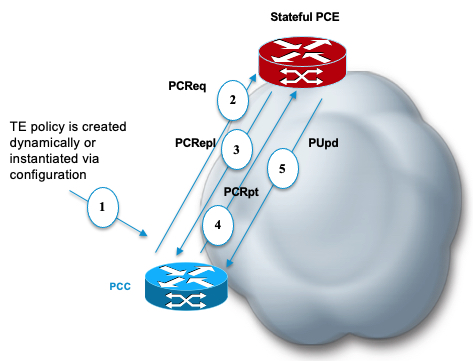
Configure the head-end router as PCEP Path Computation Client (PCC) to establish a connection to the PCE. The PCC and PCE addresses must be routable so that TCP connection (to exchange PCEP messages) can be established between PCC and PCE.

Configure the PCC to Establish a Connection to the PCE

Use the segment-routing traffic-eng pcc command to configure the PCC source address, the SR-PCE address, and SR-PCE options.

A PCE can be given an optional precedence. If a PCC is connected to multiple PCEs, the PCC selects a PCE with the lowest precedence value. If there is a tie, a PCE with the highest IP address is chosen for computing path. The precedence value range is from 0 to 255.

Router(config)# segment-routing 
Router(config-sr)# traffic-eng
Router(config-sr-te)# pcc
Router(config-sr-te-pcc)# source-address ipv6 ipv6-local-source-address
Router(config-sr-te-pcc)# pce address ipv6 ipv6-PCE-address[precedence value] 

Configure PCEP Authentication

TCP Message Digest 5 (MD5) authentication has been used for authenticating PCEP (TCP) sessions by using a clear text or encrypted password. This feature introduces support for TCP Authentication Option (TCP-AO), which replaces the TCP MD5 option.

TCP-AO uses Message Authentication Codes (MACs), which provides the following:

  • Protection against replays for long-lived TCP connections

  • More details on the security association with TCP connections than TCP MD5

  • A larger set of MACs with minimal system and operational changes

TCP-AO is compatible with Master Key Tuple (MKT) configuration. TCP-AO also protects connections when using the same MKT across repeated instances of a connection. TCP-AO protects the connections by using traffic key that are derived from the MKT, and then coordinates changes between the endpoints.


Note


TCP-AO and TCP MD5 are never permitted to be used simultaneously. TCP-AO supports IPv6, and is fully compatible with the proposed requirements for the replacement of TCP MD5.

TCP Message Digest 5 (MD5) Authentication

Use the password {clear | encrypted} LINE command to enable TCP MD5 authentication for all PCEP peers. Any TCP segment coming from the PCC that does not contain a MAC matching the configured password will be rejected. Specify if the password is encrypted or clear text

Router(config-sr-te-pcc)# pce address ipv6 ipv6-PCE-address[password {clear | encrypted} LINE]

TCP Authentication Option (TCP-AO)

Use the tcp-ao key-chain [include-tcp-options] command to enable TCP Authentication Option (TCP-AO) authentication for all PCEP peers. Any TCP segment coming from the PCC that does not contain a MAC matching the configured key chain will be rejected. Use the include-tcp-options keyword to include other TCP options in the header for MAC calculation.

Router(config-sr-te-pcc)# pce address ipv6 ipv6-PCE-address tcp-ao key-chain [include-tcp-options]

Configure PCEP-Related Timers

Use the timers keepalive command to specify how often keepalive messages are sent from PCC to its peers. The range is from 0 to 255 seconds; the default value is 30.

Router(config-sr-te-pcc)# timers keepalive seconds 

Use the timers deadtimer command to specify how long the remote peers wait before bringing down the PCEP session if no PCEP messages are received from this PCC. The range is from 1 to 255 seconds; the default value is 120.

Router(config-sr-te-pcc)# timers deadtimer seconds 

Use the timers delegation-timeout command to specify how long a delegated SR policy can remain up without an active connection to a PCE. The range is from 0 to 3600 seconds; the default value is 60.

Router(config-sr-te-pcc)# timers delegation-timeout seconds

PCE-Initiated SR Policy Timers

Use the timers initiated orphans command to specify the amount of time that a PCE-initiated SR policy will remain delegated to a PCE peer that is no longer reachable by the PCC. The range is from 10 to 180 seconds; the default value is 180.

Router(config-sr-te-pcc)# timers initiated orphans seconds

Use the timers initiated state command to specify the amount of time that a PCE-initiated SR policy will remain programmed while not being delegated to any PCE. The range is from 15 to 14440 seconds (24 hours); the default value is 600.


Router(config-sr-te-pcc)# timers initiated state seconds


Note


Multicast follows the same timer for Point-to-Multipoint (P2MP) policies:

  • The default interval is 10 minutes.

  • You can set the internal timer to '0' to ensure that forwarding states remain active indefinitely, even if the PCE is down for more than 5 minutes.

  • If the PCE is down for more than 5 minutes, it is because the PCE is going down or the reachability to PCE going down.


To better understand how the PCE-Initiated SR policy timers operate, consider the following example:

  • PCE A instantiates SR policy P at head-end N.

  • Head-end N delegates SR policy P to PCE A and programs it in forwarding.

  • If head-end N detects that PCE A is no longer reachable, then head-end N starts the PCE-initiated orphan and state timers for SR policy P.

  • If PCE A reconnects before the orphan timer expires, then SR policy P is automatically delegated back to its original PCE (PCE A).

  • After the orphan timer expires, SR policy P will be eligible for delegation to any other surviving PCE(s).

  • If SR policy P is not delegated to another PCE before the state timer expires, then head-end N will remove SR policy P from its forwarding.

Enable SR-TE SYSLOG Alarms

Use the logging policy status command to enable SR-TE related SYSLOG alarms.

Router(config-sr-te)# logging policy status

Enable PCEP Reports to SR-PCE

Use the report-all command to enable the PCC to report all SR policies in its database to the PCE.

Router(config-sr-te-pcc)# report-all

Customize MSD Value at PCC

Use the maximum-sid-depth value command to customize the Maximum SID Depth (MSD) signaled by PCC during PCEP session establishment.

The MSD is expressed as a number uSIDs. The number of uSID is expressed as a number of carriers and the number of uSID per carrier.

The default MSD value is equal to the maximum MSD supported by the platform (6 — 1 carrier, 6 uSIDs per carrier).

Router(config-sr-te-srv6)# maximum-sid-depth value

For cases with path computation at PCE, a PCC can signal its MSD to the PCE in the following ways:

  • During PCEP session establishment – The signaled MSD is treated as a node-wide property.

    • MSD is configured under segment-routing traffic-eng maximum-sid-depth value command

  • During PCEP LSP path request – The signaled MSD is treated as an LSP property.

    • On-demand (ODN) SR Policy: MSD is configured using the segment-routing traffic-eng on-demand color color maximum-sid-depth value command

    • Local SR Policy: MSD is configured using the segment-routing traffic-eng policy WORD candidate-paths preference preference dynamic metric sid-limit value command.


    Note


    If the configured MSD values are different, the per-LSP MSD takes precedence over the per-node MSD.

After path computation, the resulting uSID stack size is verified against the MSD requirement.

  • If the uSID stack size is larger than the MSD and path computation is performed by PCE, then the PCE returns a "no path" response to the PCC.

  • If the uSID stack size is larger than the MSD and path computation is performed by PCC, then the PCC will not install the path.


Note


A sub-optimal path (if one exists) that satisfies the MSD constraint could be computed in the following cases:

  • For a dynamic path with TE metric, when the PCE is configured with the pce segment-routing te-latency command or the PCC is configured with the segment-routing traffic-eng te-latency command.

  • For a dynamic path with LATENCY metric

  • For a dynamic path with affinity constraints

For example, if the PCC MSD is 4 and the optimal path (with an accumulated metric of 100) requires 5 uSIDs, but a sub-optimal path exists (with accumulated metric of 110) requiring 4 uSIDs, then the sub-optimal path is installed.


Customize the SR-TE Path Calculation

Use the te-latency command to enable ECMP-aware path computation for TE metric.

Router(config-sr-te)# te-latency


Note


ECMP-aware path computation is enabled by default for IGP and LATENCY metrics.

Configure PCEP Redundancy Type

Use the redundancy pcc-centric command to enable PCC-centric high-availability model. The PCC-centric model changes the default PCC delegation behavior to the following:

  • After LSP creation, LSP is automatically delegated to the PCE that computed it.

  • If this PCE is disconnected, then the LSP is redelegated to another PCE.

  • If the original PCE is reconnected, then the delegation fallback timer is started. When the timer expires, the LSP is redelegated back to the original PCE, even if it has worse preference than the current PCE.

Router(config-sr-te-pcc)# redundancy pcc-centric

Configuring Head-End Router as PCEP PCC and Customizing SR-TE Related Options: Example

The following example shows how to configure an SR-TE head-end router with the following functionality:

  • Enable the SR-TE head-end router as a PCEP client (PCC) with 2 PCEP servers (PCE) with different precedence values. The PCE with IP address cafe:0:2::2 is selected as BEST.

  • Enable SR-TE related syslogs.

  • Set the Maximum SID Depth (MSD) signaled during PCEP session establishment to 5.

  • Enable PCEP reporting for all policies in the node.

Node1(config)# segment-routing
Node1(config-sr)# traffic-eng
Node1(config-sr-te)# pcc
Node1(config-sr-te-pcc)# source-address ipv6 cafe:0:1::1
Node1(config-sr-te-pcc)# pce address ipv6 cafe:0:2::2
Node1(config-pcc-pce)# precedence 10
Node1(config-pcc-pce)# exit
Node1(config-sr-te-pcc)# pce address ipv6 cafe:0:3::3
Node1(config-pcc-pce)# precedence 20
Node1(config-pcc-pce)# exit
Node1(config-sr-te-pcc)# report-all
Node1(config-sr-te-pcc)# exit
Node1(config-sr-te)# srv6
Node1(config-sr-te-srv6)# maximum-sid-depth 5
Node1(config-sr-te-srv6)# exit
Node1(config-sr-te)# logging
Node1(config-sr-te-log)# policy status
Node1(config-sr-te-log)# exit
Node1(config-sr-te)#

Running Config

segment-routing
 traffic-eng
  srv6
   maximum-sid-depth 5
  !
  logging
   policy status
  !
  pcc
   source-address ipv6 cafe:0:1::1
   pce address ipv6 cafe:0:2::2
    precedence 10
   !
   pce address ipv6 cafe:0:3::3
    precedence 20
   !
   report-all
  !
 !
!

Verification

Node1# show segment-routing traffic-eng pcc ipv6 peer brief

             Address   Precedence        State    Learned From
-------------------- ------------ ------------ ---------------
         cafe:0:2::2           10           up          config
         cafe:0:3::3           20           up          config


Node1# show segment-routing traffic-eng pcc ipv6 peer detail

PCC's peer database:
--------------------

Peer address: cafe:0:2::2
  Precedence: 10, (best PCE)
  State up
  Capabilities: Stateful, Update, Segment-Routing, Instantiation
  PCEP has been up for: 01:22:23
  Local keepalive timer is 30 seconds
  Remote keepalive timer is 30 seconds
  Local dead timer is 120 seconds
  Remote dead timer is 120 seconds
  Authentication: None
  Statistics:
    Open messages:      rx 1        |  tx 1      
    Close messages:     rx 0        |  tx 0      
    Keepalive messages: rx 164      |  tx 163    
    Error messages:     rx 0        |  tx 0      
    Report messages:    rx 0        |  tx 110    
    Update messages:    rx 36       |  tx 0      

Peer address: cafe:0:3::3
  Precedence: 20
  State up
  Capabilities: Stateful, Update, Segment-Routing, Instantiation
  PCEP has been up for: 01:21:48
  Local keepalive timer is 30 seconds
  Remote keepalive timer is 30 seconds
  Local dead timer is 120 seconds
  Remote dead timer is 120 seconds
  Authentication: None
  Statistics:
    Open messages:      rx 1        |  tx 1      
    Close messages:     rx 0        |  tx 0      
    Keepalive messages: rx 164      |  tx 162    
    Error messages:     rx 0        |  tx 0      
    Report messages:    rx 0        |  tx 82     
    Update messages:    rx 0        |  tx 0 

SR-TE Application Programming Interface (API)

Table 6. Feature History Table

Feature Name

Release Information

Feature Description

SR-TE Application Programming Interface (API)

Release 7.11.1

Introduced in this release on: NCS 5500 fixed port routers; NCS 5500 modular routers (NCS 5500 line cards)

This feature introduces an API solution that simplifies the task of building SR-TE controllers and managing SRTE policies. It does so by defining gRPC API services that allow applications to request SR policy operations.

The solution leverages the gRPC Service API and GPB Data models, providing a unified, scalable, and secure method for network programming.

This feature introduces these changes:

New CLI

  • grpc segment-routing traffic-eng policy-service

YANG Data Models:

EMSD Yang model is updated to have this config under "segment-routing" container.

  • Native model: Cisco-IOS-XR-man-ems-cfg.yang

  • UM model: Cisco-IOS-XR-um-grpc-cfg.yang

(see GitHub, YANG Data Models Navigator)

SDN controllers and applications with SR traffic-engineering capabilities require a mechanism to create, monitor, and control SRv6-TE (IPv6) policies with different properties, such as optimization objectives, constraints, and segment-lists.

This feature introduces an API solution that simplifies building SR-TE controllers by defining gRPC API services to request SR policy operations. These services allow for SR policy operations, potentially including the creation, modification, or deletion of such policies. It's a more efficient and modernized approach to managing and controlling SR-TE policies.

Google-defined remote procedure call (gRPC) is an open-source RPC framework. It is based on Protocol Buffers (Protobuf), which is an open-source binary serialization protocol. gRPC provides a flexible, efficient, automated mechanism for serializing structured data, like XML, but is smaller and simpler to use. You can define the structure using protocol buffer message types in .proto files. Each protocol buffer message is a small logical record of information, containing a series of name-value pairs.

The client applications use this protocol to request information from the router and make configuration changes to the router. The process for using data models involves:

  • Obtaining the data models.

  • Establishing a connection between the router and the client using gRPC communication protocol.

  • Managing the configuration of the router from the client using data models.


Note


Refer to Use gRPC Protocol to Define Network Operations with Data Models in the Programmability Configuration Guide for Cisco NCS 5500 Series Routers.

Usage Guidelines and Limitations

  • The API is supported for SRv6-TE policies.

  • The API is not supported on the SR PCE.

SR-TE gRPC API

The SR-TE gRPC API uses the protocol buffers definition interface language (IDL) to manage the lifecycle (creation, modification, deletion) of SR-TE policies signaled by a controller/PCE and programmed at a headend.

The gRPC requests are encoded and sent to the SR-TE headend router (gRPC server) using JSON. The router can invoke the RPC calls defined in the IDL to program the SR-TE policies.

The gRPC service specifications for SR-TE, including the definitions of messages and the data model, are housed in a proto file. This SR-TE gRPC API proto file and a sample client are available in the following Github repository: https://github.com/ios-xr/SR-TE

SR-TE gRPC API proto file provides the following RPCs:

gRPC Operation Description
SRTEPolicyAdd Create and modify an SR-TE policy and its identifiers and attributes (for ex: color, endpoint, head-end, candidate paths).
SRTEPolicyDelete Delete an SR-TE policy or any of its candidate paths.

Enabling the SR-TE gRPC API on the Headend Router

Use the following commands to enable the SR-TE gRPC API:


RP/0/RP0/CPU0:ios(config)# grpc
RP/0/RP0/CPU0:ios(config-grpc)# segment-routing 
RP/0/RP0/CPU0:ios(config-grpc-sr)# traffic-eng 
RP/0/RP0/CPU0:ios(config-grpc-sr-te)# policy-service
RP/0/RP0/CPU0:ios(config-grpc-sr-te)# commit

Note


Refer to Use gRPC Protocol to Define Network Operations with Data Models in the Programmability Configuration Guide for Cisco NCS 5500 Series Routers for other gRPC parameters.

Verify

Use the show segment-routing traffic-eng service-api clients command to display the SR-TE gRPC API client and its status:

RP/0/RSP0/CPU0:ios# show segment-routing traffic-eng service-api clients
. . .

Client name: emsd (Protocol type: gRPC)
  Role: Active
  ID: 960268627
  State: Up
  Throttled: No
  Statistics:
    Client ever connected: Yes
    Connected: 00:00:12 (since Wed Nov 15 15:02:14 PST 2023)
    Number of add requests: 0
    Number of delete requests: 0
. . .

Examples

In the following examples, R1 is the SR-TE headend and the gRPC server. The headend router implements the server-side of the gRPC communication, handling requests from gRPC clients.

In these examples, an SR-TE gRPC client written in Python is used to emulate the controller node. These clients send commands to create, modify, or delete SRTE policies, and the headend router executes these commands and returns the responses.

Example 1: Programming an SRv6-TE Policy with Explicit Path via gRPC API

  1. Configure the SRv6-TE policy.

    In this example, the SRv6-TE policy uses explicit paths with a segment list. The following JSON file is passed as an input to the SR-TE gRPC client to program an SRv6-TE policy with an explicit path at the head-end router.

    controller:grpc$ more sample_srv6_explicit_path_req.json
    {
     "policies": [
      {
       "key": {
        "color": 6,
        "endpoint": "2001:0:108::1",
        "headend": "2001:0:101::1"
       },
       "CPs": [
        {
         "explicit": [
          {
           "segmentList": {
            "name": "test-srv6",
            "segments": {
             "typeB": [
              "fcbb:bb00:104::",
              "fcbb:bb00:108::"
             ]
            }
           }
          }
         ],
         "preference": 10,
         "dataplane": 1,
         "key": {
          "originatorID": {
           "ASN": 64000,
           "nodeID": "1.1.1.101"
          },
          "discriminator": 100,
          "originatorProtocol": 40
         }
        }
       ],
       "bindingSIDAllocation": 1,
       "srv6BindingSID": {
        "locatorName": "LOC_BEST_EFFORT",
        "behavior": 71
       }
      }
     ]
    }


    Execute the command/JSON file on the SR-TE gRPC client:

    controller-grpc$ srte_client -u <user> -p <password> --policy-add 
    -j sample_srv6_explicit_path_req.json -a <sr-te-headend-ip-addr>:57400
    Response: ['{"ReturnCode": 0, "Key": {"Color": 6, "Headend": "2001:0:101::1", 
    "Endpoint": "2001:0:108::1"}}']
    

    Note


    Observe the console message indicating the policy state is “UP”:
    RP/0/RP0/CPU0:Nov 15 15:11:23.784 PST: xtc_agent[1304]: %OS-XTC-5-SR_POLICY_UPDOWN : 
    SR policy 'srte_c_6_ep_2001:0:108::1' (color 6, end-point 2001:0:108::1) state changed to UP
    

  2. Verify the configuration.

    Use the following show commands to verify the configuration.

    RP/0/RP0/CPU0:R1# show segment-routing traffic-eng policy color 6
    
    SR-TE policy database
    ---------------------
    
    Color: 6 End-point: 2001:0:108::1
      Name: srte_c_6_ep_2001:0:108::1
      Status:
        Admin: up  Operational: up for 00:01:00 (since Nov 15 15:11:23.784)
      Candidate-paths:
        Preference: 10 (gRPC) (active)
          Requested BSID: dynamic
          PCC info:
            Symbolic name: gRPC_srte_c_6_ep_2001:0:108::1_c_6_ep_2001:0:108::1_discr_100
            PLSP-ID: 1
          Constraints:
            Protection Type: protected-preferred
            Maximum SID Depth: 7 
          Explicit: segment-list grpc_sl_1 (valid)
            Weight: 1, Metric Type: TE
              SID[0]: fcbb:bb00:104::/48
                      Format: f3216
                      LBL:32 LNL:16 FL:0 AL:80
              SID[1]: fcbb:bb00:108::/48
                      Format: f3216
                      LBL:32 LNL:16 FL:0 AL:80
          SRv6 Information:
            Locator: LOC_BEST_EFFORT
            Binding SID requested: Dynamic
            Binding SID behavior: uB6 (Insert.Red)
      Attributes:
        Binding SID: fcbb:bb00:101:e005::
        Forward Class: Not Configured
        Steering labeled-services disabled: no
        Steering BGP disabled: no
        IPv6 caps enable: yes
        Invalidation drop enabled: no
        Max Install Standby Candidate Paths: 0
    
    
    RP/0/RP0/CPU0:R1# show cef ipv6 fcbb:bb00:101:e005::/64
    
    fcbb:bb00:101:e005::/64, version 927, SRv6 Endpoint uB6 (Insert.Red), internal 0x1000001 0x200 (ptr 0x8b1495e8) [1], 0x400 (0x8a460958), 0x0 (0xa0e205e8)
     Updated Nov 15 15:11:23.786 
     local adjacency to TenGigE0/0/0/0
    
     Prefix Len 64, traffic index 0, precedence n/a, priority 0
      gateway array (0x8a2f3708) reference count 1, flags 0x400000, source rib (7), 0 backups
                    [2 type 3 flags 0x8401 (0x8a396cf8) ext 0x0 (0x0)]
      LW-LDI[type=3, refc=1, ptr=0x8a460958, sh-ldi=0x8a396cf8]
      gateway array update type-time 1 Nov 15 15:11:23.786
     LDI Update time Nov 15 15:11:23.787
     LW-LDI-TS Nov 15 15:11:23.787
     Accounting: Disabled
       via fe80::28a:96ff:feaa:ac00/128, TenGigE0/0/0/0, 8 dependencies, weight 1, class 0, protected, ECMP-backup (Local-LFA) [flags 0x600]
        path-idx 0 bkup-idx 1 NHID 0x0 [0xa0ffa0a0 0x0]
        next hop fe80::28a:96ff:feaa:ac00/128
        SRv6 H.Insert.Red SID-list {fcbb:bb00:104::}
       via fe80::d66a:35ff:fef3:2000/128, TenGigE0/0/0/1, 8 dependencies, weight 1, class 0, protected, ECMP-backup (Local-LFA) [flags 0x600]
        path-idx 1 bkup-idx 0 NHID 0x0 [0xa0ffa190 0x0]
        next hop fe80::d66a:35ff:fef3:2000/128
        SRv6 H.Insert.Red SID-list {fcbb:bb00:104::}
    
        Weight distribution:
        slot 0, weight 1, normalized_weight 1, class 0
        slot 1, weight 1, normalized_weight 1, class 0
        Load distribution: 0 1 (refcount 2)
    
        Hash  OK  Interface                 Address
        0     Y   TenGigE0/0/0/0            fe80::28a:96ff:feaa:ac00
        1     Y   TenGigE0/0/0/1            fe80::d66a:35ff:fef3:2000


Example 2: Programming an SRv6-TE Policy with Dynamic Path (Delegated to PCE) via gRPC API

  1. Configure the SRv6-TE policy.

    In this example, the SRv6-TE policy uses dynamic paths delegated to the PCE.

    The following JSON file is passed as an input to the SR-TE gRPC client to program an SRv6-TE policy with a dynamic path.

    controller:grpc$ more sample_srv6_dynamic_path_req.json
    {
     "policies": [
      {
       "key": {
        "color": 7,
        "endpoint": "2001:0:108::1",
        "headend": "2001:0:101::1"
       },
       "CPs": [
        {
         "dynamic": {
          "delegate": true,
          "ometric": 0
         },
         "preference": 10,
         "dataplane": 1,
         "key": {
          "originatorID": {
           "ASN": 64000,
           "nodeID": "1.1.1.101"
          },
          "discriminator": 100,
          "originatorProtocol": 40
         }
        }
       ],
       "bindingSIDAllocation": 1,
       "srv6BindingSID": {
        "locatorName": "LOC_BEST_EFFORT",
        "behavior": 71
       }
      }
     ]
    }
    

    Execute the command/JSON file on the SR-TE gRPC client:

    controller-grpc$ srte_client -u <user> -p <password> --policy-add 
    -j sample_srv6_dynamic_path_req.json -a <sr-te-headend-ip-addr>:57400 
    Response: ['{"ReturnCode": 0, "Key": {"Color": 7, "Headend": "2001:0:101::1", 
    "Endpoint": "2001:0:108::1"}}']
    

    Note


    Observe the console message indicating the policy state is “UP”:
    RP/0/RP0/CPU0:Nov 15 15:25:23.671 PST: xtc_agent[1304]: %OS-XTC-5-SR_POLICY_UPDOWN : 
    SR policy 'srte_c_7_ep_2001:0:108::1' (color 7, end-point 2001:0:108::1) state changed to UP
    

  2. Verify the configuration.

    Use the following show commands to verify the configuration.

    RP/0/RP0/CPU0:R1# show segment-routing traffic-eng pol color 7
    
    SR-TE policy database
    ---------------------
    
    Color: 7, End-point: 2001:0:108::1
      Name: srte_c_7_ep_2001:0:108::1
      Status:
        Admin: up  Operational: up for 00:01:06 (since Nov 15 15:25:23.671)
      Candidate-paths:
        Preference: 10 (gRPC) (active)
          Requested BSID: dynamic
          PCC info:
            Symbolic name: gRPC_srte_c_7_ep_2001:0:108::1_c_7_ep_2001:0:108::1_discr_100
            PLSP-ID: 3
          Constraints:
            Protection Type: protected-preferred
            Maximum SID Depth: 7 
          Dynamic (pce 2001:0:109::1) (valid)
            Metric Type: TE,   Path Accumulated Metric: 44 
              SID[0]: fcbb:bb00:103::/48 Behavior: uN (PSP/USD) (48)
                      Format: f3216
                      LBL:32 LNL:16 FL:0 AL:80
                      Address: 2001:0:103::1
              SID[1]: fcbb:bb00:104::/48 Behavior: uN (PSP/USD) (48)
                      Format: f3216
                      LBL:32 LNL:16 FL:0 AL:80
                      Address: 2001:0:104::1
              SID[2]: fcbb:bb00:107::/48 Behavior: uN (PSP/USD) (48)
                      Format: f3216
                      LBL:32 LNL:16 FL:0 AL:80
                      Address: 2001:0:107::1
              SID[3]: fcbb:bb00:108::/48 Behavior: uN (PSP/USD) (48)
                      Format: f3216
                      LBL:32 LNL:16 FL:0 AL:80
                      Address: 2001:0:108::1
          SRv6 Information:
            Locator: LOC_BEST_EFFORT
            Binding SID requested: Dynamic
            Binding SID behavior: uB6 (Insert.Red)
      Attributes:
        Binding SID: fcbb:bb00:101:e006::
        Forward Class: Not Configured
        Steering labeled-services disabled: no
        Steering BGP disabled: no
        IPv6 caps enable: yes
        Invalidation drop enabled: no
        Max Install Standby Candidate Paths: 0
    
    
    RP/0/RP0/CPU0:R1# show cef ipv6 fcbb:bb00:101:e006::/64
    
    fcbb:bb00:101:e006::/64, version 936, SRv6 Endpoint uB6 (Insert.Red), internal 0x1000001 0x200 (ptr 0x8b149100) [1], 0x400 (0x8a460918), 0x0 (0xa0e20598)
     Updated Nov 15 15:25:23.672 
     local adjacency to TenGigE0/0/0/1
    
     Prefix Len 64, traffic index 0, precedence n/a, priority 0
      gateway array (0x8a2f3618) reference count 1, flags 0x500000, source rib (7), 0 backups
                    [2 type 3 flags 0x8401 (0x8a396e58) ext 0x0 (0x0)]
      LW-LDI[type=3, refc=1, ptr=0x8a460918, sh-ldi=0x8a396e58]
      gateway array update type-time 1 Nov 15 15:25:23.672
     LDI Update time Nov 15 15:25:23.672
     LW-LDI-TS Nov 15 15:25:23.672
     Accounting: Disabled
       via fe80::28a:96ff:feaa:ac00/128, TenGigE0/0/0/0, 10 dependencies, weight 1, class 0, backup (Local-LFA) [flags 0x300]
        path-idx 0 NHID 0x0 [0x8a0c5a00 0x0]
        next hop fe80::28a:96ff:feaa:ac00/128
        local adjacency
        SRv6 H.Insert.Red SID-list {fcbb:bb00:103:104:107::}
       via fe80::d66a:35ff:fef3:2000/128, TenGigE0/0/0/1, 10 dependencies, weight 1, class 0, protected [flags 0x400]
        path-idx 1 bkup-idx 0 NHID 0x0 [0xa0ffa190 0x0]
        next hop fe80::d66a:35ff:fef3:2000/128
        SRv6 H.Insert.Red SID-list {fcbb:bb00:103:104:107::}
    
        Weight distribution:
        slot 0, weight 1, normalized_weight 1, class 0
        Load distribution: 0 (refcount 2)
    
        Hash  OK  Interface                 Address
        0     Y   TenGigE0/0/0/1            fe80::d66a:35ff:fef3:2000
    
    
    RP/0/RP0/CPU0:R1# show segment-routing traffic-eng forwarding pol color 7
    
    SR-TE Policy Forwarding database
    --------------------------------
    
    Color: 7, End-point: 2001:0:108::1
      Name: srte_c_7_ep_2001:0:108::1
      Binding SID: fcbb:bb00:101:e006::
      Active LSP:
        Candidate path:
          Preference: 10 (gRPC)
        Segment lists:
          SL[0]:
            Name: dynamic
            SL ID: 0xa000002
            Switched Packets/Bytes: ?/?
            Paths:
              Path[0]:
                Outgoing Interfaces: TenGigE0/0/0/0
                Next Hop: fe80::28a:96ff:feaa:ac00
                FRR Pure Backup: Yes
                ECMP/LFA Backup: Yes
                SID stack (Top -> Bottom): {fcbb:bb00:103::/48, fcbb:bb00:104::/48, fcbb:bb00:107::/48}
              Path[1]:
                Outgoing Interfaces: TenGigE0/0/0/1
                Next Hop: fe80::d66a:35ff:fef3:2000
                FRR Pure Backup: No
                ECMP/LFA Backup: No
                SID stack (Top -> Bottom): {fcbb:bb00:103::/48, fcbb:bb00:104::/48, fcbb:bb00:107::/48}
    
      Policy Packets/Bytes Switched: ?/?
    

Example 3: Delete the Policy

  1. On the cRPC client, run the following command to delete the policy configuration:

    controller-grpc$ srte_client -u <user> -p <password> --policy-delete 
    -j sample_srv6_explicit_path_req.json -a <sr-te-headend-ip-addr>:57400
    Response: ['{"ReturnCode": 0, "Key": {"Color": 6, "Headend": "2001:0:101::1", 
    "Endpoint": "2001:0:108::1"}}']
    
    controller-grpc$ srte_client -u <user> -p <password> --policy-delete 
    -j sample_srv6_explicit_path_req.json -a <sr-te-headend-ip-addr>:57400
    Response: ['{"ReturnCode": 0, "Key": {"Color": 7, "Headend": "2001:0:101::1", 
    "Endpoint": "2001:0:108::1"}}']
    

    Note


    Observe the console message indicating the policy state is “DOWN”:
    RP/0/RP0/CPU0:Nov 15 15:30:14.180 PST: xtc_agent[1304]: %OS-XTC-5-SR_POLICY_UPDOWN : 
    SR policy 'srte_c_6_ep_2001:0:108::1' (color 6, end-point 2001:0:108::1) state changed to DOWN (path invalidated)
    
    RP/0/RP0/CPU0:Nov 15 15:30:27.181 PST: xtc_agent[1304]: %OS-XTC-5-SR_POLICY_UPDOWN : 
    SR policy 'srte_c_7_ep_2001:0:108::1' (color 7, end-point 2001:0:108::1) state changed to DOWN (path invalidated) 
    

  2. Verify the delete operation.

    RP/0/RSP0/CPU0:ios# show segment-routing traffic-eng service-api clients
    
    Client name: emsd (Protocol type: gRPC)
      Role: Active
      ID: 440080357
      State: Up
      Throttled: No
      Statistics:
        Client ever connected: Yes
        Connected: 00:28:00 (since Wed Nov 15 15:02:14 PST 2023)
        Number of add requests: 2
        Number of delete requests: 2
    

Reporting of SR-TE Policies Using BGP- Link State

Table 7. Feature History Table

Feature Name

Release Information

Feature Description

Reporting of SR-TE Policies Using BGP-Link State for SRv6

Release 24.1.1

Introduced in this release on: NCS 5500 fixed port routers; NCS 5700 fixed port routers; NCS 5500 modular routers (NCS 5500 line cards; NCS 5700 line cards [Mode: Compatibility; Native])

You can gather the Traffic Engineering Policy information that is locally available in a node and advertise it in BGP-LS for SRv6. The configuration procedures from previous releases, which supported only SR-MPLS, are the same and apply to this feature.

Reporting of SR-TE Policies Using BGP-Link State for SR-MPLS

Release 7.10.1

Introduced in this release on: NCS 5500 fixed port routers; NCS 5700 fixed port routers; NCS 5500 modular routers (NCS 5500 line cards; NCS 5700 line cards [Mode: Compatibility; Native])

BGP- Link State (LS) is a mechanism by which LS and Traffic Engineering (TE) information can be collected from networks and shared with external components (such as, Segment Routing Path Computation Element (SR-PCE) or Crossword Optimization Engine (COE)) using the BGP routing protocol.

This feature gathers the Traffic Engineering Policy information that is locally available in a node and advertises it in BGP-LS for SR-MPLS.

The operators can now take informed decisions based on the information that is gathered on their network's path computation, reoptimization, service placement, network visualization, and so on.

The feature introduces these changes:

CLI:

YANG Data Model:

This function is achieved using a BGP Network Layer Reachability Information (NLRI) encoding format. BGP-LS consumes structured IGP data (for example, router-id, remote-IP-address of a link, local-IP address of a link, link identifier, and so on). and creates BGP-LS (NLRI) or attributes that BGP or other components like Cisco IOS XR Traffic Controller (XTC) can consume. Current implementation of BGP-LS can report topology using Nodes, Links, and Prefixes.


Note


  • Starting from Release 7.10.1 this feature supports MPLS.

  • Starting from Release 24.1.1 this feature supports SRv6.


Modern Segment Routing (SR) networks often use SR Traffic Engineering (SR-TE) to influence the path that each specific traffic takes over the network. SR-TE tunnels can be provisioned manually on the tunnel head, but often they are calculated and provisioned by the central controller. Often operator of the network wants the ability to force the traffic over specific nodes and links.

Now the operators have the option to collect reports of the SR-TE and Policy information that is locally available in a node and advertise it into BGP-LS updates, which can be used by external components. Refer the IEFT for examples. This feature is implemented so that the operators have control over their network's path computation, reoptimization, service placement, network visualization, and so on.


Note


Circuit Style (CS) SR policies are reported but without the CS policies' specific attributes, like the bidirectional constraints, per-hop behavior, and so on.


Restrictions to Reporting of SRTE Policies using BGP-LS

Some important points to be aware related to this feature are as follows:

  • This feature has high availability, ensuring BGP-LS reporting at all times.

  • This feature works with PCE State Sync. The policy information learned via the state-sync channel is not advertised in BGP-LS by the PCE.

  • The feature works with PCE redundancy. Both PCEs advertise the BGP-LS policy information. The consumers can select only one policy based on the BGP best path logic.

Configure Reporting of SRTE Policies using BGP-LS

The reporting of policies to BGP-LS is disabled by default. Configuring the distribute link-state under the SR-PCE or SR-TE configuration enables this feature. Once enabled, all the existing SR policies or Candidate Path (CPs) are encoded to BGP-LS. You can disable this feature by removing the configuration and all the SR policies or CPs are withdrawn from BGP which deletes all of the previously encoded SR policies or CPs.


Note


When SR policies that are reporting in BGP-LS are enabled by the operator, the Head End only reports the Active Candidate Path (CPs) (CPs installed in the forwarding). There are monitoring use cases that require reporting of inactive CPs. The following CLI is needed to report inactive CPs.


For both SR-TE and SR-PCE, you need to use the global CLI to enable the reporting of policies or Circuit Style (CS) to BGP-LS:


Note


  • Starting from Release 7.10.1 this feature supports MPLS.

  • Starting from Release 24.1.1 this feature supports SRv6.


Configuration Example

Configure the following command to enable reporting and syncing of SR policies in BGP-LS at the Head End:


Router# config
Router(config)# segment-routing 
Router(config-sr)# traffic-eng
Router(config-sr-te)# distribute link-state
Router(config-sr-te-distribute-ls)# report-candidate-path-inactive
Router(config-sr-te-distribute-ls)# commit
Router(config-sr-te-distribute-ls)# exit

Note


The report-candidate-path-inactive command is an optional command to report inactive CPs.


Running Configuration

This is a sample running configuration which shows that you have configured BGP-LS reporting feature.


segment-routing
 traffic-eng
  distribute link-state
   report-candidate-path-inactive
  !
 !
!

Verification

Use the show pce segment-routing traffic-eng policy private and show pce distributed-ls events to verify the configuration.


Router#show pce segment-routing traffic-eng policy private 

PCE's policy database: 
----------------------
PCC Address: 192.168.2.1
  Color: 100, Endpoint: 192.0.2.1
    Name: srte_c_100_ep_192.0.2.1
    Self Pointer: 0x317d7f0
    Active C-path Pointer: 0x317d9b0
    Candidate-paths:
      Symbolic-name: cfg_foo_discr_100 (Active)
        PLSP-ID: 1
        NB-API Notification pending flag: 0
        Self Pointer: 0x317d9b0
        Tunnel Pointer: 0x317d4e0
        Policy Pointer: 0x317d7f0
        Cached distribute LS element:
          Sense: TRUE
          Refcount: 1
          Is on queue: FALSE
          Node identifiers:
            Protocol: 9 router ID: 192.0.2.1
          Policy identifiers:
            Color: 100 Endpoint: 192.0.2.1
            Flags: 0x00
          Candidate path identifiers:
            Originator: 0.0.0.0 protocol: 3 ASN: 0
            Flags: 0x00
            Discriminator: 100
          Candidate path attributes:
            Name: foo
            Policy name: srte_c_100_ep_192.0.2.1
            State:
              Priority: 0 flags: 0x5800 (active, evaluated, valid-sid-list)
              Preference: 100
            BSID:
              Flags: 0x4000 (alloc)
              BSID: 24021
              Specified BSID: 0
            Constraints:
              Bitfield: 0x0020 flags: 0x4000 (protected-only) MT-ID: 0
              Algorithm: 0
              Bandwidth: 0 kbps
              Metric constraints[0]:
                Type: 0 flags: 0x80 (optimization)
                Margin: 0 bound: 0
              Metric constraints[1]:
                Type: 4 flags: 0x10 (bound)
                Margin: 0 bound: 10
            Segment lists:
              Segment list[0]:
                Flags: 0x3800 (computed, verified, first-seg-resolved) MT-ID: 0 algorithm: 0 weight: 0
                Metric[0]:
                  Type: 0 flags: 0x10 (value)
                  Margin: 0 bound: 0 value: 10
                Segments:
                  Segment[0]:
                    Bitfield: 0x0000 type: 3 flags: 0x8000 (sid-present)
                    SID: 102000
                    Descriptor:
                      Algorithm: 0
                      Local address: 192.0.2.1 [0] remote address: 0.0.0.0 [0]
      

Router#show pce distribute-ls events

Distribute LS events:
----------------
Event history (oldest first):
  Time                    Event
  Apr 11 01:50:48.985     [UID: 0] SR CP NLRI: node ID: SR RID 192.0.2.1, ls_id 0, asn 0, bitf 0x00000200 policy ID: endpoint: 192.168.0.2 color: 100 CP ID: originator: config 0.0.0.0 asn: 0 discriminator: 100 (oper: add)
  Apr 11 01:50:50.046     [UID: 1] SR CP NLRI: node ID: SR RID 192.0.2.1, ls_id 0, asn 0, bitf 0x00000200 policy ID: endpoint: 192.168.0.2 color: 100 CP ID: originator: config 0.0.0.0 asn: 0 discriminator: 100 (oper: add)
RP/0/0/CPU0:rtrX#show pce distribute-ls summary
Tue Apr 11 02:03:36.289 PDT
Distribution enabled: yes
Connected to LS-LIB: yes
Encode queue size: 0
Estimated encoding rate: 17280/s
NLRIs encoded to LS-LIB:
  SR candidate path: 2 added, 0 removed, 0 errored, 0 replaced
Element stats:
  SR candidate path: 1 (watermark: 2)
Throttle timer:  
  Running: no
Below is the example show output for SRv6.
Router# show segment-routing traffic-eng policy color 200 private

SR-TE policy database
---------------------
 
Color: 200, End-point: 192::2 ID: 2
  Name: srte_c_200_ep_192::2
  Status:
    Admin: up  Operational: up for 00:01:07 (since Mar  6 11:17:42.580)
  Candidate-paths:
    Preference: 100 (configuration) (active)
      Originator: ASN 0 node-address <None> discriminator: 100
      Name: bar
      Requested BSID: dynamic
      PCC info:
        Symbolic name: cfg_bar_discr_100
        PLSP-ID: 2
        Is orphan: no
        State timer:
          Running: no
      Constraints:
        Protection Type: protected-preferred
        Maximum SID Depth: 10
      ID: 1
      Source: 192::1
      Stale: no
      Checkpoint flags: 0x00000000
      Path Type: SRV6
      Performance-measurement:
        Reverse-path segment-list:
        Delay-measurement: Disabled
        Liveness-detection: Disabled
      Dynamic (pce 192.168.0.3) (valid)
        Metric Type: IGP,   Path Accumulated Metric: 10
        IGP area: 0
          SID[0]: fccc:ccc1:2::/48 Behavior: uN (PSP/USD) (48)
                  Format: f3216
                  LBL:32 LNL:16 FL:0 AL:80
                  Address: 192::2
      SRv6 Information:
        Locator: loc1Algo0
        Binding SID requested: Dynamic
        Binding SID behavior: uB6 (Insert.Red)
      Cached distribute LS element:
        Sense: TRUE
        Refcount: 1
        Is on queue: FALSE
        Node identifiers:
          Protocol: 9 router ID: 192::1
        Policy identifiers:
          Color: 200 Endpoint: 192::2
          Flags: 0x80 (endpoint-v6)
        Candidate path identifiers:
          Originator: 0.0.0.0 protocol: 3 ASN: 0
          Flags: 0x00
          Discriminator: 100
        Candidate path attributes:
          Name: bar
          Policy name: srte_c_200_ep_192::2
          State:
            Priority: 0 flags: 0x5A00 (active, evaluated, valid-sid-list, delegated)
            Preference: 100
          SRv6 BSID:
            Flags: 0x8000 (alloc)
            BSID: fccc:ccc1:1:e018::
            Specified BSID: ::
            Endpoint:
              Endpoint function: 71 flags: 0x00 algorithm: 0
            Structure:
              Locator block length: 32 locator node length: 16 function length: 16 arguments length: 0
          Constraints:
            Bitfield: 0x0020 flags: 0xC000 (dataplane-v6, protected) MT-ID: 0
            Algorithm: 0
            Bandwidth: 0 kbps
            Metric constraints[0]:
              Type: 0 flags: 0x80 (optimization)
              Margin: 0 bound: 0
            Metric constraints[1]:
              Type: 4 flags: 0x10 (bound)
              Margin: 0 bound: 10
          Segment lists:
            Segment list[0]:
              Flags: 0xB800 (dataplane-v6, computed, verified, first-seg-resolved) MT-ID: 0 algorithm: 0 weight: 1
              Metric[0]:
                Type: 0 flags: 0x10 (value)
                Margin: 0 bound: 0 value: 10
              Segments:
                Segment[0]:
                  Bitfield: 0x0003 type: 9 flags: 0x8000 (sid-present)
                  SID: fccc:ccc1:2::
                  Descriptor:
                    Algorithm: 0
                    Local address: 192::2 [0] remote address: :: [0]
                  Endpoint:
                    Endpoint function: 48 flags: 0x00 algorithm: 0
                  Structure:
                    Locator block length: 32 locator node length: 16 function length: 0 arguments length: 80
  LSPs:
    LSP[0]:
      LSP-ID: 2 policy ID: 2 (active)
      State: Programmed
      Binding SID: fccc:ccc1:1:e018::
      Install timer:
        Running: no
      Cleanup timer:
        Running: no
      Delete timer:
        Running: no
      Revert timer:
        Running: no
      SM chain:
        Init -> Egress paths
        Egress paths pending -> BSID RW
        BSID rewrite pending -> Success
      Forwarding flags: 0x00000008
      Candidate path ID: 1
      Flags:
      SL-ID:
        Sent/Received/Transferred: 1/1/0
      SLs:
        SL[0]:
          Name: dynamic
          Type: Dynamic PCE
          Checkpoint id: 1
          NH SRV6 SID: fccc:ccc1:2::
          SL ID: 0xa000001
          Flags:
          Normalized Weight: 1
          ENS: 1
          Paths:
            Path[0]:
              Interface version: 1
              Flags:
              Outgoing interface: Gi0/2/0/0
              Weight: 1
              SID stack:
              Total SID count: 0
              Underlay Normalized Weight: 1
            Path[1]:
              Interface version: 1
              Flags:
              Outgoing interface: Gi0/2/0/1
              Weight: 1
              SID stack:
              Total SID count: 0
              Underlay Normalized Weight: 1
            Path[2]:
              Interface version: 1
              Flags:
              Outgoing interface: Gi0/2/0/2
              Weight: 1
              SID stack:
              Total SID count: 0
              Underlay Normalized Weight: 1
  Attributes:
    Binding SID: fccc:ccc1:1:e018::
    Forward Class: Not Configured
    Steering labeled-services disabled: no
    Steering BGP disabled: no
    IPv6 caps enable: yes
    Invalidation drop enabled: no
    Max Install Standby Candidate Paths: 0
    Path Type: SRV6
  Notification to clients:
    Binding SID: fccc:ccc1:1:e018::
    Bandwidth : 0 Kbps (0 Kbps)
    State: UP
    Flags: [add] [ipv6_caps]
    Metric Type: IGP
    Metric Value: 10
    Admin Distance: 30
  ifhandle: 0x00000000
  Source: 192::1
  Transition count: 1
  LSPs created count: 1
  Reoptimizations completed count: 1
  Retry Action Flags: 0x00000000, ()
  Last Retry Timestamp: never (0 seconds ago)
  Policy reference: 0x1222c10
  Event history (oldest first):
    Time                    Event
    Mar  6 11:17:40.563     POLICY CREATE
    Mar  6 11:17:40.564     (x3) CP PCRPT: 1 hops:
    Mar  6 11:17:41.071     CP PCUPD: CP-ID: 1, path change: true, notify: true, hops: fccc:ccc1:2::
    Mar  6 11:17:41.072     CP PCRPT: 1 hops: fccc:ccc1:2::
    Mar  6 11:17:41.072     LSP CREATE: 2, need BSID RW: true, BSID: ::
    Mar  6 11:17:41.072     CP CHANGE: PREF: 100 [PROTO: 30, ORIGIN: 0/<None>, DISC: 100]
    Mar  6 11:17:42.579     SRv6 BSID RW REQ: ID 2
    Mar  6 11:17:42.580     SRv6 BSID RW RES: ID 2 Status: success
    Mar  6 11:17:42.580     LSP PCRPT: 2, hops: fccc:ccc1:2::
    Mar  6 11:17:42.580     CP PCRPT REMOVE: 1
    Mar  6 11:17:42.580     IM STATE CHANGE: UNKNOWN to UP, count: 0


Router# show pce segment-routing traffic-eng policy private

PCE's policy database:
----------------------
 
PCC Address: 192.168.2.1
  Color: 200, Endpoint: 192::2
    Name: srte_c_200_ep_192::2
    Self Pointer: 0x26cd890
    Active C-path Pointer: 0x26cda00
    Candidate-paths:
      Symbolic-name: cfg_bar_discr_100 (Active)
        PLSP-ID: 2
        NB-API Notification pending flag: 0
        Self Pointer: 0x26cda00
        Tunnel Pointer: 0x26cd580
        Policy Pointer: 0x26cd890
        Cached distribute LS element:
          Sense: TRUE
          Refcount: 1
          Is on queue: FALSE
          Node identifiers:
            Protocol: 9 router ID: 192::1
          Policy identifiers:
            Color: 200 Endpoint: 192::2
            Flags: 0x80 (endpoint-v6)
          Candidate path identifiers:
            Originator: 0.0.0.0 protocol: 3 ASN: 0
            Flags: 0x00
            Discriminator: 100
          Candidate path attributes:
            Name: bar
            Policy name: srte_c_200_ep_192::2
            State:
              Priority: 0 flags: 0x5A00 (active, evaluated, valid-sid-list, delegated)
              Preference: 100
            SRv6 BSID:
              Flags: 0x8000 (alloc)
              BSID: fccc:ccc1:1:e018::
              Specified BSID: ::
              Endpoint:
                Endpoint function: 71 flags: 0x00 algorithm: 0
              Structure:
                Locator block length: 32 locator node length: 16 function length: 16 arguments length: 0
            Constraints:
              Bitfield: 0x0020 flags: 0xC000 (dataplane-v6, protected) MT-ID: 0
              Algorithm: 0
              Bandwidth: 0 kbps
              Metric constraints[0]:
                Type: 0 flags: 0x80 (optimization)
                Margin: 0 bound: 0
              Metric constraints[1]:
                Type: 4 flags: 0x10 (bound)
                Margin: 0 bound: 10
            Segment lists:
              Segment list[0]:
                Flags: 0xB800 (dataplane-v6, computed, verified, first-seg-resolved) MT-ID: 0 algorithm: 0 weight: 0
                Metric[0]:
                  Type: 0 flags: 0x10 (value)
                  Margin: 0 bound: 0 value: 10
                Segments:
                  Segment[0]:
                    Bitfield: 0x0003 type: 9 flags: 0x8000 (sid-present)
                    SID: fccc:ccc1:2::
                    Descriptor:
                      Algorithm: 0
                      Local address: 192::2 [0] remote address: :: [0]
                    Endpoint:
                      Endpoint function: 48 flags: 0x00 algorithm: 0
                    Structure:
                      Locator block length: 32 locator node length: 16 function length: 0 arguments length: 80
 
 
Router# show bgp link-state link-state | i \\[SP\\]

*>i[SP][SR][I0x0][N[c100][b0.0.0.0][q192.168.0.1][te192::1]][C[po0x3][f0x80][e192::2][cl0xc8][as0][oa0.0.0.0][di100]]/792
*> [SP][SR][I0x0][N[c100][b0.0.0.0][q192.168.0.3][te192::1]][C[po0x3][f0x80][e192::2][cl0xc8][as0][oa0.0.0.0][di100]]/792


Router# show bgp link-state link-state [SP][SR][I0x0][N[c100][b0.0.0.0][q192.168.0.1][te192::1]][C[po0x3][f0x80][e192::2][cl0xc8][as0][oa0.0.0.0][di100]]/792
BGP routing table entry for [SP][SR][I0x0][N[c100][b0.0.0.0][q192.168.0.1][te192::1]][C[po0x3][f0x80][e192::2][cl0xc8][as0][oa0.0.0.0][di100]]/792
Versions:
  Process           bRIB/RIB   SendTblVer
  Speaker                128          128
Last Modified: Mar  6 11:17:43.000 for 00:04:09
Last Delayed at: ---
Paths: (1 available, best #1)
  Not advertised to any peer
  Path #1: Received by speaker 0
  Not advertised to any peer
  Local
    192.168.2.1 (metric 20) from 192.168.2.1 (192.168.0.1)
      Origin IGP, localpref 100, valid, internal, best, group-best
      Received Path ID 0, Local Path ID 1, version 128
      Link-state:
                  SRTE-CP-State: Priority: 0 Flags: 0x5a00 Preference: 100
                  SR-Policy-CP-name: bar
                  SR-Policy-name: srte_c_200_ep_192::2
                  SRTE-CP-Constraints: Flags: 0xc000 Mtid: 0 Algorithm: 0
                  SRTE-CP-Constraints-Metric: Type: 0 Flags: 0x80 Margin: 0
                  Bound: 0
                  SRTE-CP-Constraints-Metric: Type: 4 Flags: 0x10 Margin: 0
                  Bound: 10
                  SRTE-Segment-List: Flags: 0xb800 Mtid: 0 Algorithm: 0
                  Weight: 1
                  SRTE-Segment: Segment-Type: 9 Flags: 0x8000 SID: fccc:ccc1:2:: Algorithm: 0
                   Local-node: 192::2
                  SRv6-Endpoint-Fn: 48 Flags: 0x0 Algo: 0
                  SRv6-SID-Struct: LBL: 32 LNL: 16 FL: 0 AL: 80
                  SRTE-Segment-List-Metric: Type: 0 Flags: 0x10 Margin: 0
                  Bound: 0 Value: 10
                  SRTE-CP-SRV6-BSID: Flags: 0x8000 BSID: fccc:ccc1:1:e018::
                   Specified BSID: ::
                  SRv6-Endpoint-Fn: 71 Flags: 0x0 Algo: 0
                  SRv6-SID-Struct: LBL: 32 LNL: 16 FL: 16 AL: 0