Auto-Provisioning Border Gateways with Multi-Site Domains

This chapter explains LAN Fabric border provisioning using EVPN Multi-Site feature.

Border Provisioning Use Case in VXLAN BGP EVPN Fabrics - Multi-Site

This section explains how to connect two Virtual eXtensible Local Area Network (VXLAN) Border Gateway Protocol (BGP) Ethernet VPN (EVPN) fabrics through DCNM using the EVPN Multi-Site feature. The EVPN Multi-Site configurations are applied on the Border Gateways (BGWs) of the two fabrics. Also, you can connect two member fabrics of a Multi-Site Domain (MSD).

Introduced in DCNM 11.0(1) release, MSD is a multifabric container that is created to manage multiple member fabrics. It is a single point of control for definition of overlay networks and VRFs that are shared across member fabrics. See Multi-Site Domain for VXLAN BGP EVPN Fabrics section in the Control chapter for more information on MSD.

For a detailed explanation on the EVPN Multi-Site feature, see the VXLAN BGP EVPN Multi-Site Design and Deployment document.

Configuration methods - You can create underlay and overlay Inter-Fabric Connections (IFCs) between member fabrics through auto-configuration and through the DCNM GUI.

vPC configuration is supported for BGWs with the role Border Gateway from Cisco DCNM Release 11.1(1).

Supported destination devices - You can connect a VXLAN fabric to Cisco Nexus and non-Nexus devices. A connected non-Cisco device can also be represented in the topology.

Prerequisites

  • The EVPN Multi-Site feature requires Cisco Nexus 9000 Series NX-OS Release 7.0(3)I7(1) or later.

  • Familiarity with VXLAN BGP EVPN data center fabric architecture and configuration through DCNM.

  • Familiarity with MSD fabrics, if you are connecting member fabrics of an MSD fabric.

  • Fully configured VXLAN BGP EVPN fabrics that are ready to be connected using the EVPN Multi-Site feature, external fabric(s) configuration through DCNM, and relevant external fabric devices' configuration (for example, route servers).

    • VXLAN BGP EVPN fabrics (and their interconnection) can be configured manually or using DCNM. This document explains the process to connect the fabrics through DCNM. So, you should know how to configure and deploy a VXLAN BGP EVPN fabric, and how to create an external fabric through DCNM. For more details, see the VXLAN BGP EVPN Fabrics Provisioning section in the Control chapter.

  • When you enable the EVPN Multi-Site feature on a BGW, ensure that there are no prior overlay deployments on it. Remove existing overlay profiles and then start provisioning Multi-Site extensions through DCNM.

  • Execute the Save & Deploy operation in the member fabrics and external fabrics, and then in the MSD fabric.


    Note


    The Save & Deploy button appears at the top right part of the fabric topology screen (accessible through the Fabric Builder window and clicking the fabric).


  • Ensure that the role of the designated BGW is Border Gateway (or Border Gateway Spine for spine switches). To verify, right-click the BGW and click Set role. You can see that (current) is added to the current role of the switch.

  • To ensure consistency across fabrics, ensure the following:


    Note


    These checks are done for member fabrics of an MSD when the fabrics are moved under the MSD fabric.


    • The underlay IP addresses across the fabrics, the loopback 0 address and the loopback 1 address subnets should be unique. Ensure that each fabric has a unique IP address pool to avoid duplicates.

    • Each fabric should have a unique site ID and BGP AS number associated and configured.

    • All fabrics should have the same Anycast Gateway MAC address.

    • While the MSD provisions a global range of network and VRF values, some parameters are fabric-specific and some are switch-specific. You should specify fabric instance values for each fabric (for example, multicast group subnet address) and switch instance values for each switch (for example, VLAN ID).


      Note


      Case 1 - During network creation, if a VLAN is specified, then for every switch, when you attach the network to the switch, automatically the VLAN will be autopopulated with the same VLAN that was specified during network creation. The network listing screen shows the VLAN a network level which applies for all the switch (has to be the same). The other thing to keep in mind is that even if one specified a VLAN during network creation, this can still be overwritten on a per switch basis.

      Case 2 - During network creation, if a VLAN is not specified, then for every switch, when you attach the network to the switch, the next free VLAN from the per-switch VLAN pool is autopopulated. This means that on a per-switch basis, the VLAN may be different. The user can always overwrite the autopopulated VLAN and DCNM will honor it. For this case, it is possible that VNI 10000 may use VLAN 10 on leaf1 and VLAN 11 on leaf2. Hence, in the network listing, in this case, the VLAN will not be showcased.

      DCNM always keeps track of VLANs on a per switch basis in its resource manager. This is true for either of the 2 cases mentioned above.


Limitations

  • vPC configuration is not supported for the Border Gateway Spine role.

  • The VXLAN OAM feature in Cisco DCNM is only supported on a single fabric or site.

  • FEX is not supported on a Border Gateway or a Border Leaf with vPC or anycast.

Save & Deploy Operation in the MSD Fabric

These are some operations performed when you execute Save & Deploy:

  • Duplicate IP address check: The MSD fabric checks if any BGW has a duplicate IP address. If so, an error message is displayed.

    Change the BGP peering loopback IP address of the BGW(s).

    After duplicate IP address issues are resolved, execute the Save & Deploy operation again in the MSD fabric.

  • BGW base configuration: When you execute Save and Deploy for the first time in the MSD fabric (assuming there are currently no IFCs or overlays to deploy), appropriate base configurations are deployed on the BGWs. They are given below:

    Configuration

    Description

    
    evpn multisite border-gateway 7200
      delay-restore time 300
    

    7200 is the site ID of the member fabric Easy7200.

    BGP ASN value is used to auto populate the site ID field. You can override this value. Even if you change the BGP ASN value, the site ID is still set to the first BGP ASN value.

    interface nve1
    multisite border-gateway interface loopback100
    

    The loopback interface 100 is the configuration set in the MSD fabric settings. Once a loopback ID is chosen and Save and Deploy is executed, the loopback ID cannot be changed.

    To modify the role of the BGW in the MSD fabric, perform the following steps:
    1. In the easy fabric, modify the role of the BGW to leaf or border.

    2. Save and deploy the changes.

      This will remove the loopback 100 from the switch

    3. Change role back to BGW, and do a save and deploy.

    4. In the MSD fabric, change the loopback ID setting to a desired value, and do a save and deploy.

    
    interface ethernet1/47
       evpn multisite fabric-tracking
    

    The evpn multisite fabric-tracking command is configured on all ports on a Border Gateway that have a connection to a switch with a Spine role.

    In case of a Border Gateway Spine role, all ports facing the leaf switch have this command configured

    
    interface loopback100
       ip address 10.10.0.1/32 tag 54321
       ip router ospf UNDERLAY area 0.0.0.0
       ip pim sparse-mode
       no shutdown
    

    The Multi-Site loopback interface. This is configured on all Border Gateway (Spines).

    All BGWs in the same fabric get the same IP address. Each fabric gets its own unique IP address.

    It is not possible to change this address or ID without first changing role of the BGW.

    
    route-map rmap-redist-direct permit 10
       match tag 54321
    

    This is the configuration to redistribute the BGP peering loopback IP address (commonly loopback0), the VTEP primary (in case of vPC, the loopback secondary IP address), commonly loopback1, and the Multi-Site loopback IP address into the Multi-Site eBGP underlay sessions.

  • When you execute the Save & Deploy operation in the MSD fabric, it works on all the BGW (or BGW Spine) devices in the member fabrics of an MSD.

After completing the EVPN Multi-Site specific prerequisites, start EVPN Multi-Site configuration. A sample scenario is explained.

EVPN Multi-Site Configuration

The EVPN Multi-Site feature is explained through an example scenario. Consider two VXLAN BGP EVPN fabrics, Easy60000 and Easy7200, and an external fabric, External65000. The three fabrics are member fabrics of the MSD fabric MSD-Fabric and identified by a unique AS number. Easy60000 and Easy7200 are connected to a route server in External65000 (each fabric is). This document shows you how to enable end-to-end Layer 3 and Layer 2 traffic between hosts in Easy60000 and Easy7200, through the route server.

VXLAN BGP EVPN intra-fabric configurations, including network and VRF configurations are provisioned on the switches through DCNM software, 11.1(1) release. However, server traffic between the fabrics is only possible through the following configurations:

  • A Data Center Interconnect (DCI) function like the Multi-Site feature is configured on the BGWs of both the fabrics (N9K-3-BGW and N9K-4-BGW in Easy7200, and the BGW in Easy60000). As part of the configuration, since the BGWs of the fabrics are connected to the route server N7k1-RS1 in the external fabric External65000, appropriate eBGP peering configurations are enabled on the BGWs.

  • As of now, overlay networks and VRFs are enabled on the non-BGW leaf and spine switches. For a fabric’s traffic to go beyond the BGW, networks and VRFs should be deployed on all the BGWs too.

    In a nutshell, the EVPN Multi-Site feature configuration comprises of setting up the BGW base configuration (enabled during the Save & Deploy operation), the eBGP underlay and overlay peering from the three BGWs to the route server N7k1-RS1. Both the underlay and overlay peering are established over eBGP through DCNM release 11.1(1).

You can create Multi-Site Inter-Fabric Connections (IFCs) between the fabrics through the DCNM GUI or through automatic configuration. First, underlay IFC creation is explained, followed by the overlay IFC creation.

Configuring Multi-Site Underlay IFCs - DCNM GUI

The end-to-end configurations can be split into these 2 high-level steps.

Step 1 - EVPN Multi-Site configurations on the BGWs in Easy7200

Step 2 - EVPN Multi-Site configurations on the BGW in Easy60000


Note


An inter-fabric link is a physical connection between two Ethernet interfaces (an underlay connection) or a virtual connection (a fabric overlay connection between two loopback interfaces). When you add a physical connection between devices, the new link appears in the Links tab by default.


Step 1 - EVPN Multi-Site configurations on the BGWs in Easy7200

For Multi-Site connectivity from Easy7200 to the external fabric, N9K-3-BGW and N9K-4-BGW are connected to the route server N7k1-RS1 in the external fabric. Follow these steps:

Deploying underlay IFCs between Easy7200 and External65000

  • Deploying Underlay IFC from N9K-3-BGW to N7k1-RS1.

  • Deploying Underlay IFC from N9K-4-BGW to N7k1-RS1.

Deploying Underlay IFC from N9K-3-BGW to N7k1-RS1

For the Multi-Site DCNM GUI configuration option, the Deploy Border Gateway Method field in the MSD fabric’s settings (DCI tab) is set to Manual.

  1. Navigate to the Links tab and select the physical link connecting N9K-3-BGW to N7k1-RS1.

  2. Click the link edit icon as shown in the figure below to bring up the pop up.

  3. Select the MS underlay IFC sub type and fill in the required fields.


    Note


    Enter the value as 1 in the BGP Maximum Paths field to allow DCNM to pick maximum path value. Enter a value between 2 and 64 to decide the maximum path value.


  4. Save and deploy in the MSD will deploy the configuration on the N9K-3-BGW and N7k1-RS1.

    Similar steps can be used to edit already created IFCs via the Links tab.

  5. Similarly, create the underlay IFC from N9K-4-BGW to N7k1-RS1.

This completes Step 1 of the following.

Step 1 - EVPN Multi-Site configurations on the BGWs in Easy7200.

Step 2 - EVPN Multi-Site configurations on the BGW in Easy60000.

Next, configurations are enabled on the BGW in Easy60000.

Step 2 - EVPN Multi-Site configurations on the BGW in Easy60000

For Multi-Site connectivity between the Easy6000 fabric and the external fabric, EVPN Multi-Site configurations are enabled on the BGW interfaces in Easy60000 that are connected to the route server (N7k1-RS1) in the external fabric. Follow the steps as per the explanation for the connections between Easy7200 and External65000.

Configuring Multi-Site Underlay IFCs - Autoconfiguration

An underlay IFC is a physical link between the devices’ interfaces.

  • For underlay connectivity from Easy7200 to the external fabric, N9K-3-BGW and N9K-4-BGW are connected to the route server N7k1-RS1 in the external fabric.

  • For underlay connectivity from Easy60000 to the external fabric, its BGW is connected to the route server N7k1-RS1.

Deploying Multi-Site Underlay IFCs Through Autoconfiguration

The underlay generated by DCNM is an eBGP session in the default IPv4 unicast routing table, in order distribute the three loopback addresses needed for the Multi-Site control plane and data plane to function correctly.

For the Multi-Site autoconfiguration option, the underlay IFCs are automatically deployed by the MSD fabric.

The following rules apply to Multi-Site underlay IFC creation:

  1. Check the Multi-Site Underlay IFC Auto Deployment Flag check box to enable the multi-site underlay autoconfiguration. Uncheck the check box to disable autoconfiguration. The check box is unchecked by default.

  2. An IFC is deployed on every physical connection between the BGWs of different member fabrics that are physically connected.

  3. An IFC is deployed on every physical connection between a BGW and a router with the role Core Router imported into an external fabric which is a member of the MSD fabric.

    If you do not want an IFC to be auto generated on a connection, then shut the link, execute the Save & Deploy operation, and delete the undesired IFCs. Also, ensure that there is no existing policy or pre-configured IP address on the interface. Else, use the Manual mode.

  4. The IP addresses used to deploy the underlay are derived from the IP address range in the DCI Subnet IP Range field (DCI tab) of the MSD fabric.

Just like overlay IFCs, Multi-Site underlay IFCs can be viewed via the MSD, external and member fabrics. Also, the underlay IFCs can be edited and deleted via the VXLAN or MSD fabrics.

Configuring Multi-Site Underlay IFCs Towards a Non-Nexus Device - DCNM GUI

In this case, the non-Nexus device is not imported into DCNM, or discovered through Cisco Discovery Protocol or Link Layer Discovery Protocol (LLDP). For example, a Cisco ASR 9000 Series router or even a non-Cisco device.

The steps are similar to the Configuring Multi-Site Underlay IFCs - DCNM GUI task.

  1. In the Fabric Builder window, choose the Easy7200 fabric.

    The Easy7200 topology window appears.

  2. From the Actions panel at the left, click Tabular view.

    The Switches | Links window appears.

  3. Click the Links tab and click +.

    The Add Link window appears.

  4. Fill in the fields.

    Link Type – Choose Inter-Fabric.

    Link Sub-Type – Choose MULTISITE_UNDERLAY.

    Link Template - By default, the ext_multisite_underlay_setup_11_1 template is populated.

    Source Fabric - Easy7200 is selected by default since the IFC is created from Easy7200 to the ASR device.

    Destination Fabric – Select the external fabric. In this case, External65000 is selected.

    Source Device and Source Interface - Choose the border device and the interface that is connected to the ASR device.

    Destination Device - Type any string that identifies the device. The destination device ASR9K-RS2 does not appear in the drop-down list when you create an IFC for the first time. Once you create an IFC towards ASR9K-RS2 and associate it with the external fabric External65000, ASR9K-RS2 appears in the list of devices displayed in the Destination Device field.

    Also, after the first IFC creation, ASR9K-RS2 is displayed in the External65000 external fabric topology, within Fabric Builder.

    Destination Interface - Type any string that identifies the interface.

    You have to manually enter the destination interface name each time.

    General tab in the Link Profile section.

    Source BGP ASN - In this field, the AS number of the source fabric Easy7200 is autopopulated.

    Source IP Address/Mask - Enter the IP address and mask that is used as the local interface for the Multi-Site underlay IFC.

    Destination IP - Enter the IP address of the ASR9K-RS2 interface used as the eBGP neighbor.

    Destination BGP ASN - In this field, the AS number of the external fabric External65000 is autopopulated since it is chosen as the external fabric.

  5. Click Save at the bottom right of the window.

    The Switches|Links window appears again. You can see that the IFC entry is updated.

  6. Click Save and Deploy at the top right of the window.

    The link on which the IFC is deployed has the relevant policy configured in the Policy column.

  7. Go to the Scope drop-down list at the top right of the window and choose External65000. The external fabric Links window is displayed. You can see that the IFC created from Easy7200 to the ASR device is displayed here.

Configuring Multi-Site Overlay IFCs

An overlay IFC is a link between the devices’ loopback0 interfaces.

Deploying Overlay IFCs in Easy7200 and Easy60000 comprises of these steps:

  • Deploying Overlay IFC from N9K-3-BGW to N7k1-RS1.

  • Deploying Overlay IFC from N9K-4-BGW to N7k1-RS1.

  • Deploying the Overlay IFC from the BGW in Easy60000 to N7k1-RS1.

Deploying Overlay IFCs between Easy7200 and External65000

  • Deploying Overlay IFC from N9K-3-BGW to N7k1-RS1.

  • Deploying Overlay IFC from N9K-4-BGW to N7k1-RS1.

Deploying Overlay IFCs - from N9K-3-BGW to N7k1-RS1

  1. Click Control > Fabric Builder. The Fabric Builder window appears.

  2. Choose the MSD fabric, MSD-Fabric. The fabric topology comes up.

  3. Click Tabular view. The Switches | Links screen comes up.

  4. Click the Links tab. It lists links within the MSD fabric. Each row either represents an intra-fabric link within Easy7200 or Easy60000, or a link between border devices of member fabrics, including External65000.

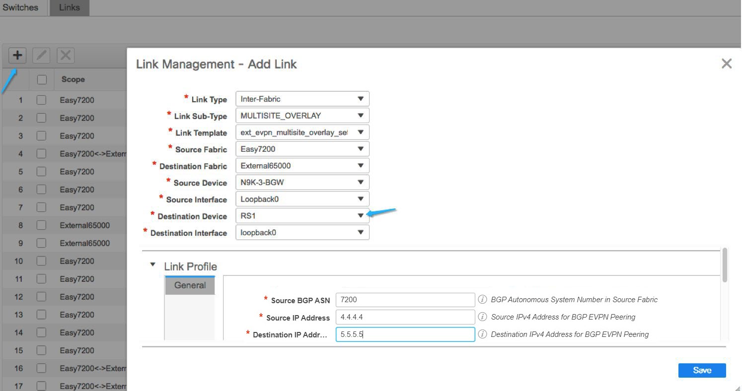
  5. Click the Add Link icon at the top left part of the screen.

    The Link Management – Add Link screen comes up.

    Some fields are explained:

    Link Type – Inter-Fabric is autopopulated.

    Link Sub-Type – Choose MULTISITE_OVERLAY.

    Link Template – The default template for creating an overlay is displayed.

    You can edit the template or create a new one with custom configurations.

    In the General tab, the BGP AS numbers of Easy7200 and External65000 are displayed. Fill in the other fields as explained. The BGP AS numbers are derived based on fabric values.

  6. Click Save at the bottom right part of the screen.

    The Switches|Links screen comes up again. You can see that the IFC entry is updated.

  7. Click Save & Deploy at the top right part of the screen.

  8. Go to the Scope drop-down list at the top right of the window and choose External65000. The external fabric Links screen is displayed. You can see that the two IFCs created from Easy7200 to External65000 is displayed here.


    Note


    When you create an IFC or edit its setting in the VXLAN fabric, the corresponding entry is automatically created in the connected external fabric.


  9. Click Save and Deploy to save the IFCs creation on External65000.

  10. Similarly, create an overlay IFC from N9K-4-BGW to N7k1-RS1.

    After the overlay IFCs from N9K-3-BGW and N9K-4-BGW to N7k1-RS1 are deployed, the fabric overlay traffic can flow between Easy7200 and External65000.

  11. Similarly, deploy the overlay IFC from the BGW in the Easy60000 fabric to N7k1-RS1.

Configuring Multi-Site Overlay IFCs - Autoconfiguration

An overlay IFC is a link between the devices’ loopback0 interfaces. For overlay connectivity from the Easy7200 and Easy60000 fabrics to the route server N7k1-RS1 in External65000, a link is enabled between the BGW devices and the N7k1-RS1’s loopback0 interfaces.

Deploying Overlay IFCs in Easy7200 and Easy60000

  • Deploying Overlay IFC from N9K-3-BGW to N7k1-RS1.

  • Deploying Overlay IFC from N9K-4-BGW to N7k1-RS1.

  • Deploying the Overlay IFC from the BGW in Easy60000 to N7k1-RS1.

Deploying Multi-Site Overlay IFCs Through Autoconfiguration

You can automatically configure the Multi-Site overlay through one of these options:

  1. Route Server - The BGW forms an overlay to the route server. This option is explained in the example.

  2. Direct to BGW: A full mesh of Multi-Site Overlay IFC from every BGW in a fabric to every BGW in other member fabrics.

To choose one of the above options, go to the MSD fabric’s settings, select the DCI tab, and set the Deploy Border Gateway Method field to Route_Server (such as for this example) or Direct to BGW. By default, the Manual option is selected.

The IFCs needed for deployment of Networks and VRFs at the BGW nodes can be auto configured via the MSD fabric template. The settings to enable that are in MSD fabric template.

The default mode for the Deploy Border Gateway Method field is Manual, which implies that the IFCs have to be created via the link tab in MSD fabric. It must be changed to the Route_Server or Direct to BGW mode for autoconfiguration.

The IFCs created via auto configuration can only be edited or deleted via the link tab in MSD or member fabrics (except external fabric). As long as an IFC exists, or there is any user defined policy on the physical or logical link, auto configuration will not touch the IFC configuration.

You can see that Route_Server is selected in the Deploy Border Gateway Method field in the above image.

Route Server

This implies that all BGW devices in all member fabrics will create a Multi-Site overlay BGP connection to one or more route servers in one or more external fabrics which are members of the MSD fabric.

In this topology, there is one route server n7k1-RS1, and its BGP peering address (1.1.1.1) is shown in the route server list. This peering address can be configured out of band or with create interface tab in DCNM. N7k1-RS1 must be imported into the DCNM (in the external fabric, in this example) and the peering address configured before executing the Save & Deploy option.

You can edit the route server peering IP address list at any time, but you can delete a configured Multi-Site overlay only through the Links tab.

The BGP AS number of each route server should be specified in the MSD fabric settings. Note that the route server AS number can be different than the fabric AS number of the external fabric.

Configuring Multi-Site Overlay IFCs Towards a Non-Nexus Device - DCNM GUI

In this case, the non-Nexus device is not imported into DCNM, or discovered through Cisco Discovery Protocol or Link Layer Discovery Protocol (LLDP). For example, a Cisco ASR 9000 Series router or even a non-Cisco device.

The steps are similar to the Configuring Multi-Site Overlay IFCs - DCNM GUI task.

  1. In the Fabric Builder window, choose the Easy7200 fabric.

    The Easy7200 topology window appears.

  2. From the Actions panel, click Tabular view.

    The Switches | Links window appears.

  3. Click the Links tab and click +.

    The Add Link screen comes up.

  4. Fill in the fields.

    Link Type – Choose Inter-Fabric.

    Link Sub-Type – Choose MULTISITE_OVERLAY.

    Link Template – By default, the ext_evpn_multisite_overlay_setup template is populated.

    Source FabricEasy7200 is selected by default since the IFC is created from Easy7200 to the ASR device.

    Destination Fabric – Select the external fabric. In this case, External65000 is selected.

    Source Device and Source Interface - Choose the border device and the loopback0 interface that is the source interface of the overlay.

    Destination Device: Type any string that identifies the device. The destination device ASR9K-RS1 does not appear in the drop-down list when you create an IFC for the first time. Once you create an IFC towards ASR9K-RS1 and associate it with the external fabric External65000, ASR9K-RS1 appears in the list of devices displayed in the Destination Device field.

    Also, after the first IFC creation, ASR9K-RS1 is displayed in the External65000 topology screen, within Fabric Builder.

    Destination Interface: Type any string that identifies the interface.

    You have to manually enter the destination interface name each time.

    General tab in the Link Profile section.

    Source BGP ASN: In this field, the AS number of the source fabric Easy7200 is autopopulated.

    Source IP Address/Mask: Enter the IP address of the loopback0 interface for the Multi-Site overlay IFC.

    Destination IP: Enter the IP address of the ASR9K-RS1 loopback interface used for this Multi-Site overlay IFC.

    Destination BGP ASN: In this field, the AS number of the external fabric External65000 is autopopulated since it is chosen as the external fabric.

  5. Click Save at the bottom right part of the screen.

    The Switches|Links screen comes up again. You can see that the IFC entry is updated.

  6. Click Save and Deploy at the top right part of the screen.

    The link on which the IFC is deployed has the relevant policy configured in the Policy column.

  7. Go to the Scope drop-down list at the top right of the window and choose External65000. The external fabric Links screen is displayed. You can see that the overlay IFC is displayed here.

Overlay and Underlay Peering Configurations on the Route Server N7k1-RS1

When you execute the Save and Deploy operation in the MSD fabric during the IFCs creation, peering configurations are enabled on the router server N7k1-RS1 towards the BGWs in the VXLAN fabrics.

Viewing, Editing and Deleting Multi-Site Overlays

The overlay IFCs can be viewed via the MSD and member fabrics Links tab as shown below.

The IFCs can be edited and deleted in the member fabric or in the MSD fabric.

Multi-Site overlay IFCs can also be created by the links tab in MSD fabric.

Once the IFC is deleted, you should execute the Save & Deploy operation in the external and VXLAN fabric (or MSD fabric) to undeploy the IFC on the switches and remove the intent from DCNM.


Note


Until a particular IFC is completely deleted from DCNM, auto configuration will not regenerate it on a Save & Deploy operation in the MSD fabric.


Deleting Multi-Site IFCs

  1. Navigate to the Links tab, select the IFCs to be deleted and click the Delete icon as shown below.

  2. Perform a Save & Deploy in the MSD fabric to complete deletion.


    Note


    If auto configuration of IFCs is enabled in the MSD fabric settings, then performing a Save & Deploy may regenerate the IFC intent.


If all or large number of IFCs are to be deleted, then temporarily change the BGW deploy mode to Manual setting before performing Save & Deploy.

  • Deleting IFC in a non-Nexus Switch: If you delete the last IFC in a non-Nexus switch, the switch is removed from the topology. From Cisco DCNM Release 11.2(1), you can remove non-Nexus switches and neighbor switches like a physical switch from the Tabular view window or from the fabric topology window by right-clicking the switch and choosing Discovery > Remove from fabric in the drop-down menu.

  • Removing a fabric from an MSD fabric: Before removing a fabric from an MSD fabric, remove all the multisite overlays from all BGWs in that fabric. Otherwise, you will not be able to remove the fabric. After the following save and deploy in the easy fabric, all the multisite configurations, such as IFC, multisite loopback address configured in MSD are removed from BGWs.

  • Device role change: You can change the device role from Border to Border Gateway, but the role change from Border Gateway to Border is allowed only if there are no multisite IFCs or overlays deployed on the device.

Creating and Deploying Networks and VRFs in the MSD Fabric

Networks and VRFs can be created from the MSD context in the Networks and VRF page, these can be deployed on BGW nodes for all member fabrics of that MSD.

The following screenshots show how to select networks and deploy them. From the MSD fabric context, any device can be selected for network or VRF deployment. However, networks or VRFs can be deployed only on BGWs from the MSD context in the network deployment screen. The leaf deployment can be done from the fabric context or from the Fabric Builder context.

Deploying Networks with a Layer 3 Gateway on a BGW

Perform the following steps:


Note


Selecting an interface to deploy SVI is only available on vPC BGW setups. This is a device limitation not a DCNM limitation.


  1. In order to deploy a network with a Layer 3 gateway on a Border device (Border, Border spine, Border Gateway, Border Gateway spine), perform these steps.

    When creating the network, check the Enable L3 gateway on Border check box, as shown in the figure below. Note that this a network wide setting, so whenever this network is deployed on the Border device, the Layer 3 gateway will be deployed. If this is required on only a subset of the Borders, then a custom template is required.

    When deploying the network on the Border device, select the interface(s) in the Interface column in case of vPC BGW.

    Just like the leaf switch, the candidate ports should have int_trunk_host_policy_11_1, otherwise they will not be in the interface list.

    The interface policy can be modified through the Control > Interfaces tab.

  2. When deploying the network on the vPC pair of BGWs, select the interface(s) in the Interfaces column. Only vPC port channel interfaces are the candidate interfaces.

Deploying a Legacy Site BGW (vPC-BGWs)

The recommended way of integrating non-VXLAN BGP EVPN (legacy) and VXLAN BGP EVPN fabrics is by using a pair of VPC BGWs. For more information about this method, see NextGen DCI with VXLAN EVPN Multi-Site Using vPC Border Gateways White Paper.

The vPC BGW method replaces the Pseudo-Border Gateway method recommended in the DCNM release 11.1(1).

In this section, the tasks from the white paper that can be accomplished by DCNM are explained with an example topology.

Prerequisites

  • Legacy network is already setup by a method. This is out of the scope for this document.

  • Familiarity with fabric creation and Multi-Site use case.

Tasks Overview

The following information is covered as part of this section:

  1. Fabrics to be created using DCNM:

    1. VXLAN fabric with vPC border gateways.

    2. Easy Fabric for VXLAN.

    3. External fabric for Route Server. Note that this fabric is optional if you are using Direct to BGWs topology.

    4. External fabric to monitor the legacy devices.

    5. MSD fabric as a container for all fabrics.

  2. vPC connection from vPC BGWs towards the legacy site. It is expected that vPC from legacy towards BGWs is done out of band.

  3. Multi-Site underlay eBGP inter-fabric connection (IFC) creation.

  4. Multi-Site overlay eBGP IFC creation.

Topology Overview

Let us look at the example topology.

This topology contains the following five fabrics:

  1. GATEWAY

    This fabric is created for the vPC border gateways.

    This fabric is an Easy fabric without any Spine nodes and it is set up as a regular Easy fabric with the following characteristics:

    • Under the Replication tab, the Replication Mode is set to Ingress.

    • The vPC Border gateways role are set as BGW.

    • The IFC create method will be set to Manual or auto configuration as per user preference.

    • Gateway fabric has a vPC interface configuration towards the Legacy Fabric.

    • A member fabric of MSD.

    • Save and deploy operation is performed in Easy fabric and MSD fabric.

  2. LEGACY

    This fabric is created for the Legacy network. The fabric type is External and could be kept in the monitor mode. Fully configured devices are imported into this fabric as shown in External Fabric procedure.

  3. EasyFabric01

    This represents a fully functional VXLAN fabric. The Border Gateway switches of this fabric are connected via IFC’s to Route Servers or Direct to BGWs of Legacy fabric as per your topology. Both models are supported as shown in the Multi-Site use case.

  4. RouteServers

    In this topology, Centralized to Route Server topology is used. Typically, there would be more than one Route Server for redundancy reasons. This fabric is of type External as shown in the Multi-Site use case.

  5. MSD

    The MSD fabric is created to configure the base multi-site for the member fabrics. All the above four fabrics are imported into the MSD fabric for the BGW base. Optionally, you can enable auto-configuration of all underlay and overlay IFCs.

Configuring vPC from vPC Border Gateways to Legacy Network

In the Manage Interfaces window for the GATEWAY fabric, click the Add (+) icon and enter the information for the fields as shown in the following image. From the Policy drop-down list, select the vPC policy and fill in the fields for your topology.

After entering all the information, click Preview to preview the configurations that are deployed, and then click Deploy.

Multi-Site Underlay eBGP IFC Creation

The Multi-Site underlay configuration is same as MSD shown in the Multi-Site use case. Choose GUI or autoconfiguration based method to create IFCs to the Core router or directly to BGW of other fabric, as per your topology.

In this topology, vPC Border Gateways are physically connected to Route Server (RS1), one MS underlay IFC is configured from each BGW (in GATEWAY and EasyFabric01) to RS1. Both methods are detailed in the Multi-Site use case.

Configuring Multi-Site Overlay IFCs

Multi-Site overlay IFCs need to be created between vPC BGWs to either a centralized route server or Direct to each BGW in EasyFabric01. In the example topology, there is one Overlay IFC from each BGW to RS1.

The summary of the IFCs for this topology are shown in the following image.

Appendix

Multi-Site Fabric Base Configurations – Box Topology

In the Easy7200 fabric, N9K-3-BGW and N9K-4-BGW are connected to each other over two physical interfaces, and the BGWs do not form a vPC pair. Such a topology is called a Box topology. An IBGP session is configured on each physical connection. One connection is between the Eth1/21 interfaces, and the other is between the Eth1/22 interfaces.

IBGP Configuration for the Box Topology in the Easy7200 Fabric

The following configuration is generated on each of the nodes if the fabric has numbered interfaces. In case the fabric interfaces are unnumbered, then the IBGP session is formed via the loopback0 address.

N9K-BGW-3

N9K-BGW-4


router bgp 7200
   neighbor 10.4.0.17
      remote-as 7200
      update-source ethernet1/22
      address-family ipv4 unicast
      next-hop-self

router bgp 7200
  neighbor 10.4.0.18
    remote-as 7200
    update-source Ethernet1/22
    address-family ipv4 unicast
      next-hop-self

router bgp 7200
   neighbor 10.4.0.13
      remote-as 7200
      update-source ethernet1/21
      address-family ipv4 unicast
      next-hop-self

router bgp 7200
 neighbor 10.4.0.14
    remote-as 7200
    update-source Ethernet1/21
    address-family ipv4 unicast
      next-hop-self

interface ethernet1/22
  evpn multisite dci-tracking
  no switchport
  ip address 10.4.0.18/30
  description connected-to-N9K-4-BGW--Ethernet1/22  

interface Ethernet1/22
  evpn multisite dci-tracking
  no switchport
  ip address 10.4.0.17/30
  description connected-to-N9K-3-BGW-Ethernet1/22

interface ethernet1/21
  evpn multisite dci-tracking
  no switchport
  ip address 10.4.0.14/30
  description connected-to-N9K-4-BGW-Ethernet1/21

interface Ethernet1/21
  evpn multisite dci-tracking
  no switchport
  ip address 10.4.0.13/30
  description connected-to-N9K-3-BGW-Ethernet1/21

Changing loopback0 Policy to Modify IP Address

Route Server Configuration

The route server overlay and base configurations are only deployed if the external fabric is not in Monitor mode.


Note


When an external fabric is set to Fabric Monitor Mode Only, you cannot deploy configurations on its switches. Refer the Creating an External Fabric topic in the Control chapter for details.


Route Server Base Configuration - These are one time deployed on the route server and may be edited or deleted via the corresponding policy. The router server overlay and base configurations are only deployed if the external fabric is not in Monitor mode.

Configuration

Description


route-map unchanged permit 10
  set ip next-hop unchanged
_

router bgp 65000
  address-family ipv4 unicast
    network /32

The network command to redistribute the BGP peering address of RS1 to the eBGP underlay sessions so that BGWs know how to reach RS.

If operator is using a different method to distribute the route server peering address to BGW, then this is not needed


interface ethernet1/22
  evpn multisite dci-tracking
  no switchport
  ip address 10.4.0.18/30
  description connected-to-N9K-4-BGW--Ethernet1/22  

interface Ethernet1/22
  evpn multisite dci-tracking
  no switchport
  ip address 10.4.0.17/30
  description connected-to-N9K-3-BGW-Ethernet1/22

template peer OVERLAY-PEERING
    update-source loopback0
    ebgp-multihop 5
    address-family l2vpn evpn
      route-map unchanged out
      address-family l2vpn evpn
         retain route-target all
         send-community
         send-community extended

The knob in the external fabric controls if send community is sent in the form shown here, or as send-community both.

If this form causes a persistent CC difference, then edit the policy on the device in the external fabric as shown in the Deploying the Send-Community Both Attribute section below.

Multi-Site Overlay IFC Configuration

In the reference topology, there are two BGWs in the Easy7200 fabric. Each BGW forms a BGP overlay connection with the route server.

BGW

Route Server


router bgp 7200
   neighbor 
     remote-as 65000
     update-source loopback0
     ebgp-multihop 5
     peer-type fabric-external
     address-family l2vpn evpn
       send-community
       send-community extended
       rewrite-evpn-rt-asn

router bgp 65000
  neighbor 10.2.0.1
   remote-as 7200
   inherit peer OVERLAY-PEERING
   address-family l2vpn evpn
     rewrite-evpn-rt-asn
router bgp 65000
   neighbor 10.2.0.2
   remote-as 7200
   inherit peer OVERLAY-PEERING
   address-family l2vpn evpn
     rewrite-evpn-rt-asn

See below for the configurations generated on the BGW and the route server.

Multi-Site Underlay IFC Configuration – Out-of-Box Profiles

The following table shows the Multi-Site IFC configuration deployed by DCNM with the out-of-the box profiles. If the IFC is between two VXLAN fabrics, then both sides have the BGW configurations shown below.

BGW Configuration

Core Router Configuration


router bgp 7200
   neighbor 10.10.1.6
   remote-as 65000
   update-source ethernet1/47
   address-family ipv4 unicast
     next-hop-self

router bgp 65000
   neighbor 10.10.1.5
     remote-as 7200
     update-source ethernet7/4/1
     address-family ipv4 unicast
       next-hop-self

interface ethernet1/47
  mtu 9216
  no shutdown
  no switchport
  ip address 10.10.1.5/30 tag 54321
  evpn multisite dci-tracking


interface ethernet7/4/1
  mtu 9216
  no shutdown
  no switchport
  ip address 10.10.1.6/30 tag 54321

The tag 54321 attached to the IP address is not required for correct functioning and will be removed in subsequent releases. It is benign.