Object Management

This chapter describes how to manage reusable objects.

Introduction to Objects

For increased flexibility and web interface ease-of-use, the system uses named objects, which are reusable configurations that associate a name with a value. When you want to use that value, use the named object instead. The system supports object use in various places in the web interface, including many policies and rules, event searches, reports, dashboards, and so on. The system provides many predefined objects that represent frequently used configurations.

Use the object manager to create and manage objects. Many configurations that use objects also allow you to create objects on the fly, as needed. You can also use the object manager to:

After you edit an object used in an active policy, you must redeploy the changed configuration for your changes to take effect. You cannot delete an object that is in use by an active policy.


Note


An object is configured on a managed device if, and only if, the object is used in a policy that is assigned to that device. If you remove an object from all policies assigned to a given device, the object is also removed from the device configuration on the next deployment, and subsequent changes to the object are not reflected in the device configuration.


Object Types

The following table lists the objects you can create in the system, and indicates whether each object type can be grouped or configured to allow overrides.

Object Type

Groupable?

Allows Overrides?

Network

yes

yes

Port

yes

yes

Interface:

  • Security Zone

  • Interface Group

no

no

Tunnel Zone

no

no

Application Filter

no

no

VLAN Tag

yes

yes

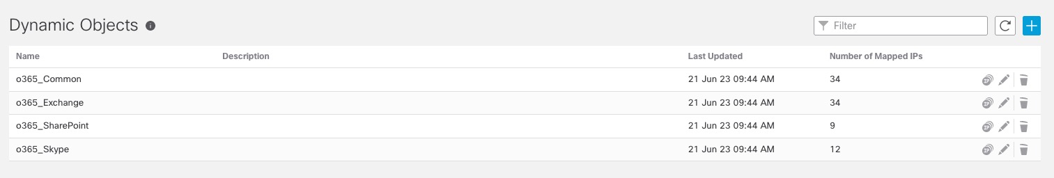
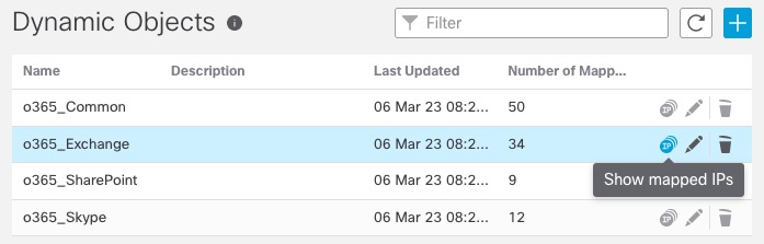
External Attribute: Security Group Tag (SGT) and Dynamic Object

no

no

URL

yes

yes

Geolocation

no

no

Time Range

no

no

Variable Set

no

no

Security Intelligence: Network, DNS, and URL lists and feeds

no

no

Sinkhole

no

no

File List

no

no

Cipher Suite List

no

no

Distinguished Name

yes

no

Public Key Infrastructure (PKI):

  • Internal and Trusted CA

  • Internal and External Certs

yes

no

Key Chain no yes

DNS Server Group

no

no

SLA Monitor

no

no

Prefix List: IPv4 and IPv6

no

yes

Route Map

no

yes

Access List: Standard and Extended

no

yes

AS Path

no

yes

Community List

no

yes

Policy List

no

yes

FlexConfig: Text and FlexConfig objects

no

yes

Objects and Multitenancy

In a multidomain deployment, you can create objects in Global and descendant domains with the exception of Security Group Tag (SGT) objects, which you can create only in the Global domain. The system displays objects created in the current domain, which you can edit. It also displays objects created in ancestor domains, which you cannot edit, with the exception of security zones and interface groups.


Note


Because security zones and interface groups are tied to device interfaces, which you configure at the leaf level, administrators in descendant domains can view and edit and groups created in ancestor domains. Subdomain users can add and delete interfaces from ancestor zones and groups, but cannot delete or rename the zones/groups.


Object names must be unique within the domain hierarchy. The system may identify a conflict with the name of an object you cannot view in your current domain.

For objects that support grouping, you can group objects in the current domain with objects inherited from ancestor domains.

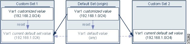
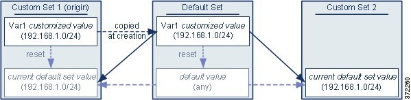
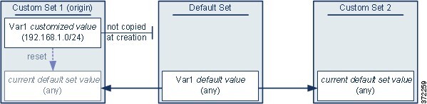
Object overrides allow you to define device-specific or domain-specific values for certain types of object, including network, port, VLAN tag, and URL. In a multidomain deployment, you can define a default value for an object in an ancestor domain, but allow administrators in descendant domains to add override values for that object.

The Object Manager

You can use the object manager to create and manage objects and object groups.

The object manager displays 20 objects or groups per page. If you have more than 20 of any type of object or group, use the navigation links at the bottom of the page to view additional pages. You can also go to a specific page or click Refresh (refresh icon) to refresh your view.

By default, the page lists objects and groups alphabetically by name. You can filter the objects on the page by name or value.

Importing Objects

Objects can be imported from a comma-separated values file. Up to 1000 objects can be imported in one attempt. The contents of the comma-separated values file should follow a specific format. The format is different for each object type. Only a few types of objects can be imported. See the following table to know the supported object types and the corresponding rules.

Object Type

Rules

Individual object

  • The column header must be mentioned in capital letters.

  • The file must have the following columns headers:

    • NAME

    • DN

  • Both NAME and DN column entries are mandatory to import an entry.

  • You can import individual objects directly into an existing distinguished name object group.

Network object

  • The column header must be mentioned in capital letters.

  • The file must have the following columns headers:

    • NAME

    • DESCRIPTION

    • TYPE

    • VALUE

    • LOOKUP

  • The NAME and VALUE column entries are mandatory to import an entry of host, range, or network object type.

  • For an FQDN object, the TYPE column entry must mention 'fqdn,' and the LOOKUP column entry must be specified as 'ipv4,' 'ipv6,' or 'ipv4_ipv6.'

  • If no content is provided in the LOOKUP column entry for the FQDN object, then the object is saved with the ipv4_ipv6 field value.

Port

  • The column header must be mentioned in capital letters.

  • The file must have the following columns headers:

    • NAME

    • PROTOCOL

    • PORT

    • ICMPCODE

    • ICMPTYPE

  • The NAME column entry is mandatory.

  • For 'tcp' and 'udp' protocol types, the PORT column entry is mandatory.

  • For 'icmp' and 'icmp6' protocol types, the ICMPCODE and ICMPTYPE column entries are mandatory.

URL

  • The column header must be mentioned in capital letters.

  • The file must have the following columns headers:

    • NAME

    • DESCRIPTION

    • URL

  • The NAME and URL column entries are mandatory to import an entry.

VLAN Tag

  • The column header must be mentioned in capital letters.

  • The file must have the following columns headers:

    • NAME

    • DESCRIPTION

    • TAG

  • The NAME and TAG column entries are mandatory to import an entry.

Procedure


Step 1

Choose Objects > Object Management.

Step 2

Choose one of the following object types from the left pane:

  • Distinguished Name > Individual Objects >

  • Network Object

  • Port

  • URL

  • VLAN Tag

Step 3

Choose Import Object from the Add [Object Type] drop-down list.

Note


If you have selected Individual Objects in the previous step, click Import.

Step 4

Click Browse.

Step 5

Locate and select the comma-separated file on your system.

Step 6

Click Open.

Note


While importing Distinguished Name objects, you can optionally check the Add imported Distinguished Name objects to the below object group check box and select the group name from the drop-down box to import the objects directly to an existing distinguished name object group.

Step 7

Click Import.


Editing Objects

Procedure


Step 1

Choose Objects > Object Management.

Step 2

Choose an object type from the list; see Introduction to Objects.

Step 3

Click Edit (edit icon) next to the object you want to edit.

If View (View button) appears instead, the object belongs to an ancestor domain and has been configured not to allow overrides, or you do not have permission to modify the object.

Step 4

Modify the object settings as desired.

Step 5

If you are editing a variable set, manage the variables in the set; see Managing Variables.

Step 6

For objects that can be configured to allow overrides:

  • If you want to allow overrides for this object, check the Allow Overrides check box; see Allowing Object Overrides. You can change this setting only for objects that belong to the current domain.
  • If you want to add override values to this object, expand the Override section and click Add; see Adding Object Overrides.

Step 7

Click Save.

Step 8

If you are editing a variable set, and that set is in use by an access control policy, click Yes to confirm that you want to save your changes.


What to do next

Viewing Objects and Their Usage

You can view usage details of objects on the Object Management page. Management Center provides this functionality for many object types. However, some object types are not supported.

Procedure


Step 1

Choose Objects > Object Management.

Step 2

Choose one of the following supported object types:

  • Access List > Extended

  • Access List > Standard

  • AS Path

  • Community List

  • Interface

  • Network

  • Policy List

  • Port

  • Prefix List > IPv4 Prefix List

  • Prefix List > IPv6 Prefix List

  • Route Map

  • SLA Monitor

  • URL

  • VLAN Tag

Step 3

Click the Find Usage (find usage icon) icon next to the object.

The Object Usage window displays a list of all the policies, objects, and other settings where the object is in use. Click any of the listed items to know more about the object usage. For policies and some other settings where the object is used, you can click the corresponding links to visit the respective UI pages.


Filtering Objects or Object Groups

Procedure


Step 1

Choose Objects > Object Management.

Step 2

Enter your filter criteria in the Filter field.

The page updates as you type to display matching items.

You can use the following wildcards:

  • The asterisk (*) matches zero or more occurrences of a character.

  • The caret (^) matches content at the beginning of a string.

  • The dollar sign ($) matches content at the end of a string.

Step 3

Check the Show Unused Object check box to view the objects and the object groups that are unused anywhere in the system.

Note

 
  • In case an object is a part of an unused object group, the object is considered as used. However, the unused object group is displayed when the Show Unused Object check box is checked.

  • The Show Unused Object check box is available only for network, port, URL and VLAN tag object types.


Object Groups

Grouping objects allows you to reference multiple objects with a single configuration. The system allows you to use objects and object groups interchangeably in the web interface. For example, anywhere you would use a port object, you can also use a port object group.

You can group network, port, VLAN tag, URL, and PKI objects. Network object groups can be nested, that is, you can add a network object group to another network object group up to 10 levels.

Objects and object groups of the same type cannot have the same name.

When you edit an object group used in a policy (for example, a network object group used in an access control policy), you must re-deploy the changed configuration for your changes to take effect.

Deleting a group does not delete the objects in the group, just their association with each other. Additionally, you cannot delete a group that is in use in an active policy. For example, you cannot delete a VLAN tag group that you are using in a VLAN condition in a saved access control policy.

Grouping Reusable Objects

Procedure

Step 1

Choose Objects > Object Management.

Step 2

If the object type you want to group is Network, Port, URL, or VLAN Tag:

  1. Choose the object type from the list of object types.

  2. Choose Add Group from the Add [Object Type] drop-down list.

Step 3

If the object type you want to group is Distinguished Name:

  1. Expand the Distinguished Name node.

  2. Choose Object Groups.

  3. Click Add Distinguished Name Group.

Step 4

If the object type you want to group is PKI:

  1. Expand the PKI node.

  2. Choose one of the following:

    • Internal CA Groups

    • Trusted CA Groups

    • Internal Cert Groups

    • External Cert Groups

  3. Click Add [Object Type] Group.

Step 5

Enter a unique Name.

Step 6

Choose one or more objects from the list, and click Add.

You can also:

  • Use the filter field Search (search icon) to search for existing objects to include, which updates as you type to display matching items. Click Reload (reload icon) above the search field or click Clear (clear icon) in the search field to clear the search string.

  • Click Add (add icon) to create objects on the fly if no existing objects meet your needs.

Step 7

Optionally for Network, Port, URL, and VLAN Tag groups:

  • Enter a Description.
  • Check the Allow Overrides check box to allow overrides for this object group; see Allowing Object Overrides.

Step 8

Click Save.


What to do next

Object Overrides

An object override allows you to define an alternate value for an object, which the system uses for the devices you specify.

You can create an object whose definition works for most devices, and then use overrides to specify modifications to the object for the few devices that need different definitions. You can also create an object that needs to be overridden for all devices, but its use allows you to create a single policy for all devices. Object overrides allow you to create a smaller set of shared policies for use across devices without giving up the ability to alter policies when needed for individual devices.

For example, you might want to deny ICMP traffic to the different departments in your company, each of which is connected to a different network. You can do this by defining an access control policy with a rule that includes a network object called Departmental Network. By allowing overrides for this object, you can then create overrides on each relevant device that specifies the actual network where that device is connected.

You can target an object override to a specific domain. In this case, the system uses the object override value for all devices in the targeted domain unless you override it at the device level.

From the object manager, you can choose an object that can be overridden and define a list of device-level or domain-level overrides for that object.

You can use object overrides with the following object types only:

  • Network

  • Port

  • VLAN tag

  • URL

  • SLA Monitor

  • Prefix List

  • Route Map

  • Access List

  • AS Path

  • Community List

  • Policy List

  • Cert Enrollment (PKI)

  • Key Chain

If you can override an object, the Override column appears for the object type in the object manager. Possible values for this column include:

  • Green checkmark — indicates that you can create overrides for the object and no overrides have been added yet

  • Red X — indicates that you cannot create overrides for the object

  • Number — represents a count of the overrides that have been added to that object (for example, "2" indicates two overrides have been added)

Managing Object Overrides

Procedure

Step 1

Choose Objects > Object Management.

Step 2

Choose from the list of object types; see Introduction to Objects.

Step 3

Click Edit (edit icon) next to the object you want to edit.

If View (View button) appears instead, the object belongs to an ancestor domain and has been configured not to allow overrides, or you do not have permission to modify the object.

Step 4

Manage the object overrides:


Allowing Object Overrides

Procedure

Step 1

In the object editor, check the Allow Overrides check box.

Step 2

Click Save.


What to do next

Add object override values; see Adding Object Overrides.

Adding Object Overrides

Before you begin

Allow object overrides; see Allowing Object Overrides.

Procedure

Step 1

In the object editor, expand the Override section.

Step 2

Click Add.

Step 3

On Targets, choose domains or devices in the Available Devices and Domains list and click Add.

Step 4

On the Override tab, enter a Name.

Step 5

Optionally, enter a Description.

Step 6

Enter an override value.

Example:

For a network object, enter a network value.

Step 7

Click Add.

Step 8

Click Save.


What to do next

Editing Object Overrides

You can modify the description and the value of an existing override, but you cannot modify the existing target list. Instead, you must add a new override with new targets, which replaces the existing override.

Procedure

Step 1

In the object editor, expand the Override section.

Step 2

Click Edit (edit icon) next to the override you want to modify.

Step 3

Optionally, modify the Description.

Step 4

Modify the override value.

Step 5

Click Save to save the override.

Step 6

Click Save to save the object.


What to do next

AAA Server

Add reusable AAA server objects.

Add a RADIUS Server Group

RADIUS Server Group objects contain one or more references to RADIUS servers. These servers are used to authenticate users logging in through Remote Access VPN connections.

You can use this object with threat defense devices.

Before you begin


Note


You cannot override RADIUS Server Group Objects.


Procedure


Step 1

Select Objects > Object Management > AAA Server > RADIUS Server Group.

All currently configured RADIUS Server Group objects will be listed. Use the filter to narrow down the list.

Step 2

Choose and edit a listed RADIUS Server Group object, or add a new one.

See RADIUS Server Options and RADIUS Server Group Options to configure this object.

Step 3

Click Save


RADIUS Server Group Options

Navigation Path

Objects > Object Management > AAA Server > RADIUS Server Group. Choose and edit a configured RADIUS Server Group object or add a new one.

Fields
  • Name and Description—Enter a name and optionally, a description to identify this RADIUS Server Group object.

  • Group Accounting Mode—The method for sending accounting messages to the RADIUS servers in the group. Choose Single, accounting messages are sent to a single server in the group, this is the default. Or, Multiple, accounting messages are sent to all servers in the group simultaneously.

  • Retry Interval—The interval between attempts to contact the RADIUS servers. Values range from 1 to 10 seconds.

  • Realms(Optional)—Specify or select the Active Directory (AD) realm this RADIUS server group is associated with. This realm is then selected in identity policies to access the associated RADIUS server group when determining the VPN authentication identity source for a traffic flow. This realm effectively provides a bridge from the identity policy to this Radius server group. If no realm is associated with this RADIUS server group, the RADIUS server group cannot be reached to determine the VPN authentication identity source for a traffic flow in an identity policy.


    Note


    This field is mandatory if you use remote access VPN with User Identity and RADIUS as the identity source.


  • Enable authorize only—If this RADIUS server group is not being used for authentication, but is being used for authorization or accounting, check this field to enable authorize-only mode for the RADIUS server group.

    Authorize only mode eliminates the need of including the RADIUS server password in the Access-Request. Thus, the password, configured for the individual RADIUS servers, is ignored.

  • Enable interim account update and Interval—Enables the generation of RADIUS interim-accounting-update messages in order to inform the RADIUS server of newly assigned IP addresses. Set the length, in hours, of the interval between periodic accounting updates in the Interval field. The valid range is 1 to 120 and the default value is 24.

  • Enable Dynamic Authorization and Port— Enables the RADIUS dynamic authorization or change of authorization (CoA) services for this RADIUS server group. Specify the listening port for RADIUS CoA requests in the Port field. The valid range is 1024 to 65535 and the default value is 1700. Once defined, the corresponding RADIUS server group will be registered for CoA notification and it listens to the port for the CoA policy updates from the Cisco Identity Services Engine (ISE).

  • Merge Downloadable ACL with Cisco AV Pair ACL—Enables merging a downloadable access control list (dACL) with a Cisco attribute-value (AV) pair ACL.

    A downloadable ACL defines and updates access control lists in CiscoISE and allows ACL download to all the applicable controllers. For more information about using dACLs in Cisco ISE, see the chapter on Segmentation, section on authorization policies, in the Cisco ISE Administrator Guide.

    A Cisco AV pair ACL can be utilized to define specific authentication, authorization, and accounting elements for each individual session. For more information about using dACLs in Cisco ISE, see the chapter on Segmentation, section on authorization profile settings, in the Cisco ISE Administrator Guide.

    If you select Merge Downloadable ACL with Cisco AV Pair ACL, you can choose the following options:

    • After Cisco AV Pair ACL means the downloadable ACL entries should be placed after the Cisco AV pair entries.

    • Before Cisco AV Pair ACL means the downloadable ACL entries should be placed before the Cisco AV pair entries.

  • RADIUS Servers—See RADIUS Server Options.

RADIUS Server Options

Navigation Path

Objects > Object Management > AAA Server > RADIUS Server Group. Choose and edit a listed RADIUS Server Group object or add a new one. Then, in the RADIUS Server Group dialog, choose and edit a listed RADIUS Server or add a new one.

Fields
  • IP Address/Hostname—The network object that identifies the hostname or IP address of the RADIUS server to which authentication requests will be sent. You may only select one, to add additional servers, add additional RADIUS Server to the RADIUS Server Group list.


    Note


    The device now supports IPv6 IP addresses for RADIUS authentication.


  • Authentication Port—The port on which RADIUS authentication and authorization are performed. The default is 1812.

  • Key and Confirm Key— The shared secret that is used to encrypt data between the managed device (client) and the RADIUS server.

    The key is a case-sensitive, alphanumeric string of up to 127 characters. Special characters are permitted.

    The key you define in this field must match the key on the RADIUS server. Enter the key again in the Confirm field.

  • Accounting Port—The port on which RADIUS accounting is performed. The default is 1813.

  • Timeout— Session timeout for authentication.


    Note


    The timeout value must be 60 seconds or more for RADIUS two factor authentication. The default timeout value is 10 seconds.


  • Connect Using —Establishes connectivity from the device to a RADIUS server using a route lookup or using a specific interface.

    • Click the Routing radio button to use the routing table.

    • Click the Specific Interface radio button and choose a security zone/interface group or the Management interface (the default) from the drop-down list. If you want to use Management, you must choose it specifically; it is not available when using a route lookup. You cannot specify any other management-only interface as the RADIUS source. You can also choose a loopback interface group.

  • Redirect ACL—Select the redirect ACL from the list or add a new one.


    Note


    This is the name of the ACL defined in the device to decide the traffic to be redirected. The Redirect ACL name here must be the same as the redirect-acl name in ISE server. When you configure the ACL object, ensure that you select Block action for ISE and DNS servers, and Allow action for the rest of the servers.


Add a Single Sign-on Server

Before you begin

Obtain the following from your SAML identity provider:

  • Identity Provider Entity ID URL

  • Sign-in URL

  • Sign-out URL

  • Identity provider certificate and enroll the certificate in threat defense using the management center web interface (Devices > Certificates)

For more information, see Configuring a SAML Single Sign-On Authentication.

Procedure


Step 1

Choose Object > Object Management > AAA Server > Single Sign-on Server.

Step 2

Click Add Single Sign-on Server and provide the following details:

  • Name—The name of the SAML single sign-on server object.

  • Identity Provider Entity ID—The URL that is defined in SAML IdP to identify a service provider uniquely.

    The URL for a page that serves a metadata XML that describes how the SAML Issuer is going to respond to requests.

  • SSO URL—The URL for signing into the SAML identity provider server.

  • Logout URL—The URL for signing out of the SAML identity provider server.

  • Base URL—URL that will redirect the user back to threat defense once the identity provider authentication is done. This is the URL of the access interface configured for the threat defense remote access VPN.

  • Identity Provider Certificate—Certificate of the IdP enrolled into the threat defense to verify the messages signed by the IdP.

    Select an identify provider certificate from the list or click Add to create a new certificate enrollment object.

    For more information, see Managing Threat Defense Certificates.

    You must enroll all of the Microsoft Azure registered application CA certificates as Trustpoints on the threat defense. The Microsoft Azure SAML identity provider is configured on threat defense for the initial application. All connection profiles are mapped to the configured MS Azure SAML identity provider. For each of the MS Azure applications (other than the default), you can choose the required trustpoint(CA certificate) in the connection profile configuration of the remote access VPN.

    For details, see Configure AAA Settings for Remote Access VPN.

  • Service Provider Certificatethreat defense certificate, which will be used to sign the requests and build circle of trust with IdP.

    If you have not enrolled internal threat defense certificates, click + to add and enroll a certificate. For more information, see Managing Threat Defense Certificates.

  • Request Signature—Select the encryption algorithm to sign the SAML single sign-on requests.

    The signatures are listed from weakest to strongest: SHA1,SHA256, SHA384, SHA512. Select None to disable encryption.

  • Request Timeout—Specify the SAML assertion validity duration for the users to complete the single sign-on request. The SAML IdP has two time outs: NotBefore and NotOnOrAfter. The threat defense validates if its current time is within the time range of (lower limit) NotBefore and (upper limit) the smaller of NotBefore plus timeout and NotOnOrAfter. Thus, if you set a timeout longer than the IdP's NotOnOrAfter timeout, the specified timeout is ignored and the NotOnOrAfter timeout is selected. If the sum of the specified timeout and the NotBefore timeout is less than the NotOnOrAfter time, threat defense timeout overrides the timeout.

    The timeout range is 1-7200 seconds; the default is 300 seconds.

  • Enable IdP only accessible on Internal Network—Select this option if the SAML IdP resides on the internal network. Threat Defense acts as a gateway and establishes communication between the users and IdP using an anonymous webvpn session.

  • Request IdP re-authentication on Login—Select this option to authenticate user at each login even if the previous IdP session is valid.

  • Allow Overrides—Select this check box to allow overrides for this single sign-on server object.

Step 3

Click Save.


Access List

An access list object, also known as an access control list (ACL), selects the traffic to which a service will apply. You use these objects when configuring particular features, such as route maps, for threat defense devices. Traffic identified as allowed by the ACL is provided the service, whereas “blocked” traffic is excluded from the service. Excluding traffic from a service does not necessarily mean that it is dropped altogether.

You can configure the following types of ACL:

  • Extended—Identifies traffic based on source and destination address and ports. Supports IPv4 and IPv6 addresses, which you can mix in a given rule.

  • Standard—Identifies traffic based on destination address only. Supports IPv4 only.

An ACL is composed of one or more access control entry (ACE), or rule. The order of ACEs is important. When the ACL is evaluated to determine if a packet matches an “allowed” ACE, the packet is tested against each ACE in the order in which the entries are listed. After a match is found, no more ACEs are checked. For example, if you want to “allow” 10.100.10.1, but “block” the rest of 10.100.10.0/24, the allow entry must come before the block entry. In general, place more specific rules at the top of an ACL.

Packets that do not match an “allow” entry are considered to be blocked.

The following topics explain how to configure ACL objects.

Configure Extended ACL Objects

Use extended ACL objects when you want to match traffic based on source and destination addresses, protocol and port, application group or if the traffic is IPv6.

Procedure


Step 1

Select Objects > Object Management and choose Access List > Extended from the table of contents.

Step 2

Do one of the following:

  • Click Add Extended Access List to create a new object.

  • Click Edit (edit icon) to edit an existing object.

Step 3

In the New Extended Access List Object dialog box, enter a name for the object (no spaces allowed), and configure the access control entries:

  1. Do one of the following:

    • Click Add to create a new entry.

    • Click Edit (edit icon) to edit an existing entry.

  2. Select the Action, whether to Allow (match) or Block (not match) the traffic criteria.

    Note


    The Logging, Log Level, and Log Interval options are used for access rules only (ACLs attached to interfaces or applied globally). Because ACL objects are not used for access rules, leave these values at their defaults.

  3. Configure the source and destination addresses on the Network tab using any of the following techniques:

    • Select the desired network objects or groups from the Available list and click Add to Source or Add to Destination. You can create new objects by clicking the + button above the list. You can mix IPv4 and IPv6 addresses.

    • Type an address in the edit box below the source or destination list and click Add. You can specify a single host address (such as 10.100.10.5 or 2001:DB8::0DB8:800:200C:417A), or a subnet (in 10.100.10.0/24 or 10.100.10.0 255.255.255.0 format, or for IPv6, 2001:DB8:0:CD30::/60).

  4. Click the Port tab and configure the service using any of the following techniques.

    • Select the desired port objects from the Available list and click Add to Source or Add to Destination. You can create new objects by clicking the + button above the list. The object can specify TCP/UDP ports, ICMP/ICMPv6 message types, or other protocols (including “any”). However, the source port, which you typically would leave empty, accepts TCP/UDP only. You cannot select port groups.

      For TCP/UDP, note that you must use the same protocol in both the source and destination fields, if you specify both. For example, you cannot specify a UDP source port and a TCP destination port.

    • Type or select a port or protocol in the edit box below the source or destination list and click Add.

    Note


    To get an entry that applies to all IP traffic, select a destination port object that specifies “all” protocols.

  5. Click the Application tab and choose the applications that are to be grouped for the direct internet access policy.

    Important

     
    • You cannot configure applications for cluster devices. Hence, this tab is not applicable for cluster devices.

    • Use extended ACL with applications only in Policy Based Routing. Do not use it in other policies as its behavior is unknown and not supported.

    Note

     
    • The Available Applications list displays a fixed set of pre-defined applications. This list is a subset of the applications that are available on the Access Control policy as only they can be detected by their first packet (FQDN end-points resolved to IP addresses and port). The application definitions are updated through the VDB updates and are pushed to threat defense during subsequent deployments.

    • User-defined custom applications or group of applications are not supported.

    • Currently, management center neither supports user-defined custom applications or group of applications nor allows you to modify the pre-defined applications list.

    • You can use the filter options provided under the Application Filters to refine this list.

  6. Click the Users tab and choose the users, user groups, or both that are to be classified for the Policy Based Routing (PBR).

    Important


    Use extended ACL with users, user groups, or both only for Policy Based Routing. Do not use it in other policies as its behavior is unknown and not supported.

    Note

     
    • The Available Realms list displays the configured active directory/LDAP realms. For information on creation of realm and managing them, see Create an LDAP Realm or an Active Directory Realm and Realm Directory and Manage a Realm respectively.

      Note


      Local realms and Azure AD realms are not supported.

    • The Available Users list displays the downloaded users and user groups of the selected AD/LDAP realms. To download the users, user groups, or both, navigate to Integrations > Other Integrations > Realms, and then click Download against the relevant active directory/LDAP realms.

      Note


      Threat defense can support a maximum of 512 user groups and 64000 user-IP mappings.

    • The user to IP mapping and user group membership information are updated and pushed to the threat defense from the management center during the user login or logouts, and changes in the group memberships.

  7. Click the Security Group Tag tab and choose the source SGT tags to be classified for the direct internet access policy.

    Important


    Use extended ACL with SGTs only for Policy Based Routing. Do not use it in other policies as its behavior is unknown and not supported.

    Note

     
  8. Select the required application, and click Add to Rule.

    Note

     
    • Do not configure destination networks and applications in the extended ACL object.

    • The selected applications (Nertwork Service objects) in each of the access control entries, form a Network Service Group (NSG) and this group is deployed on the threat defense. The NSG is used in direct internet access to classify traffic based on the match with the selected application group.

  9. Click Add to add the entry to the object.

  10. If necessary, click and drag the entry to move it up or down in the rule order to the desired location.

    Repeat the process to create or edit additional entries in the object.

Step 4

If you want to allow overrides for this object, check the Allow Overrides check box; see Allowing Object Overrides.

Step 5

Click Save.


Configure Standard ACL Objects

Use standard ACL objects when you want to match traffic based on destination IPv4 address only. Otherwise, use extended ACLs.

Procedure


Step 1

Select Objects > Object Management and choose Access List > Standard from the table of contents.

Step 2

Do one of the following:

  • Click Add Standard Access List to create a new object.

  • Click Edit (edit icon) to edit an existing object.

Step 3

In the New Standard Access List Object dialog box, enter a name for the object (no spaces allowed), and configure the access control entries:

  1. Do one of the following:

    • Click Add to create a new entry.

    • Click Edit (edit icon) to edit an existing entry.

  2. For each access control entry, configure the following properties:

    • Action—Whether to Allow (match) or Block (not match) the traffic criteria.

    • Network—Add the IPv4 network objects or groups that identify the destination of the traffic.

  3. Click Add to add the entry to the object.

  4. If necessary, click and drag the entry to move it up or down in the rule order to the desired location.

    Repeat the process to create or edit additional entries in the object.

Step 4

If you want to allow overrides for this object, check the Allow Overrides check box; see Allowing Object Overrides.

Step 5

Click Save.


Address Pools

You can configure IP address pools for both IPv4 and IPv6 that can be used for clustering or for VPN remote access profiles. For clustering in Individual interface mode, you can also configure MAC address pools.

Procedure


Step 1

Select Objects > Object Management > Address Pools.

Step 2

Click IPv4 Pools and then Add IPv4 Pools, and configure the following fields.

  • Name—Enter the name of the address pool. It can be up to 64 characters

  • Description—Add an optional description for this pool.

  • IP Address—Enter a range of addresses available in the pool. Use dotted decimal notation and a dash between the beginning and the end address, for example: 10.10.147.100-10.10.147.177.

  • Mask—Identifies the subnet on which this IP address pool resides.

  • Allow Overrides—Check this check box to enable object overrides. Click the expand arrow to show the Overrides table. You can add a new override by clicking Add. See Object Overrides for more information.

Step 3

Click Save.

Step 4

Click IPv6 Pools and then Add IPv6 Pools, and configure the following fields.

  • Name—Enter the name of the address pool. It can be up to 64 characters

  • Description—Add an optional description for this pool.

  • IPv6 Address—Enter the first IP address available in the configured pool and the prefix length in bits. For example: 2001:DB8::1/64.

  • Number of Addresses—Identifies the number of IPv6 addresses, starting at the Starting IP Address, that are in the pool.

  • Allow Overrides—Check this check box to enable overrides. Click the expand arrow to show the Overrides table. You can add a new override by clicking Add. See Object Overrides for more information.

Step 5

Click Save.

Step 6

Click MAC Address Pool and then Add MAC Address Pool, and configure the following fields.

For clustering in Individual interface mode, you can configure a MAC address pool for the interface. It is not common to manually configure MAC addresses for an interface, but if you have special needs to do so, then this pool is used to assign a unique MAC address to each interface. See Configure the MAC Address.

  • Name—Enter the name of the address pool. It can be up to 64 characters

  • Description—Add an optional description for this pool.

  • MAC Address Range—Enter a range of MAC addresses available in the pool. Use a dash between the beginning and the end address, for example: 000C.F142.4CD1-000C.F142.4CD7.

  • Allow Overrides—Check this check box to enable overrides. Click the expand arrow to show the Overrides table. You can add a new override by clicking Add. See Object Overrides for more information.


Application Filters

System-provided application filters help you perform application control by organizing applications according to basic characteristics: type, risk, business relevance, category, and tags. In the object manager, you can create and manage reuseable user-defined application filters based on combinations of the system-provided filters, or on custom combinations of applications. For detailed information, see Application Rule Conditions.

AS Path

An AS Path is a mandatory attribute to set up BGP. It is a sequence of AS numbers through which a network can be accessed. An AS-PATH is a sequence of intermediate AS numbers between source and destination routers that form a directed route for packets to travel. Neighboring autonomous systems (ASes ) use BGP to exchange and update messages about how to reach different AS prefixes. After each router makes a new local decision on the best route to a destination, it will send that route, or path information, along with the accompanying distance metrics and path attributes, to each of its peers. As this information travels through the network, each router along the path prepends its unique AS number to a list of ASes in the BGP message. This list is the route's AS-PATH. An AS-PATH along with an AS prefix, provides a specific handle for a one-way transit route through the network. Use the Configure AS Path page to create, copy and edit autonomous system (AS) path policy objects. You can create AS path objects to use when you are configuring route maps, policy maps, or BGP Neighbor Filtering. An AS path filter allows you to filter the routing update message by using regular expressions.

You can use this object with threat defense devices.

Procedure


Step 1

Select Objects > Object Management and choose AS Path from the table of contents.

Step 2

Click Add AS Path.

Step 3

Enter a name for the AS Path object in the Name field. Valid values are between 1 and 500.

Step 4

Click Add on the New AS Path Object window.

  1. Select the Allow or Block options from the Action drop-down list to indicate redistribution access.

  2. Specify the regular expression that defines the AS path filter in the Regular Expression field.

  3. Click Add.

Step 5

If you want to allow overrides for this object, check the Allow Overrides check box; see Allowing Object Overrides.

Step 6

Click Save.


BFD Template

The BFD template specifies a set of BFD interval values. BFD interval values as configured in the BFD template are not specific to a single interface. You can also configure authentication for single-hop and multi-hop sessions. Echo mode is disabled by default. You can enable Echo mode on single-hop only.

Procedure


Step 1

Choose Objects > Object Management > BFD Template.

Step 2

Click Add BFD Template or Edit.

Note


If you are editing a template, you cannot modify its name and type.

Step 3

On the Template tab, configure the following:

  • Template Name—The name of this BFD template. You must assign a name in order to configure the rest of the parameters in the template. The template name cannot have spaces and cannot have only numbers.

  • Type—Click the Single-Hop or Multi-Hop radio button.

  • Enable Echo—(Optional) Enables Echo for the single-hop template.

If the Echo function is not negotiated, BFD control packets are sent at a high rate to meet the detection time. If the Echo function is negotiated, BFD control packets are sent at a slower, negotiated rate and self-directed echo packets are sent at a high rate. We recommend that you use Echo mode, if possible.

Step 4

On the Interval tab, configure the following:

  1. From the Interval Type drop-down list, select Microseconds or Milliseconds.

  2. In the Multiplier field, enter the value to be used for computing the hold down time. This value indicates the number of consecutive BFD control packets that must be missed from a BFD peer before BFD declares that the peer is unavailable and the Layer 3 BFD peer is informed of the failure. The range is 3 to 50. The default is 3.

  3. In the Minimum Transmit field, enter the minimum transmit interval capability. The range is 50 to 999 milliseconds or 50000 to 999000 microseconds.

  4. In the Minimum Receive field, enter the minimum receive interval capability. The range is 50 to 999 milliseconds or 50000 to 999000 microseconds.

Step 5

On the Authentication tab, configure the following:

  • Authentication Type—Select NONE, md5, meticulous-sha-1, meticulous-md5, or sha-1 from the drop-down list.

  • Encrypted Password—(Optional) Enables encryption of the authentication password.

  • Password—The authentication password that must be sent and received in the packets using the routing protocol being authenticated. The valid value is a string containing 1 to 29 uppercase and lowercase alphanumeric characters, except that the first character CANNOT be a digit or a digit followed by a whitespace. For example, '1password' or '0 password' is invalid.

  • Key ID—The shared key ID that matches the key value. The range is 0 to 255.

Step 6

Click OK.

Step 7

Click Apply to save the BFD template configuration.


Cipher Suite List

A cipher suite list is an object comprised of several cipher suites. Each predefined cipher suite value represents a cipher suite used to negotiate an SSL- or TLS-encrypted session. You can use cipher suites and cipher suite lists in SSL rules to control encrypted traffic based on whether the client and server negotiated the SSL session using that cipher suite. If you add a cipher suite list to an SSL rule, SSL sessions negotiated with any of the cipher suites in the list match the rule.


Note


Although you can use cipher suites in the web interface in the same places as cipher suite lists, you cannot add, modify, or delete cipher suites.


Creating Cipher Suite Lists

Procedure


Step 1

Choose Objects > Object Management.

Step 2

Choose Cipher Suite List from the list of object types.

Step 3

Click Add Cipher Suites.

Step 4

Enter a Name.

Step 5

Choose one or more cipher suites from the Available Ciphers list.

Step 6

Click Add.

Step 7

Optionally, click Delete (delete icon) next to any cipher suites in the Selected Ciphers list that you want to remove.

Step 8

Click Save.


What to do next

Community List

A Community is an optional transitive BGP attribute. A community is a group of destinations that share some common attribute. It is used for route tagging. The BGP community attribute is a numerical value that can be assigned to a specific prefix and advertised to other neighbors. Communities can be used to mark a set of prefixes that share a common attribute. Upstream providers can use these markers to apply a common routing policy such as filtering or assigning a specific local preference or modifying other attributes. Use the Configure Community Lists page to create, copy and edit community list policy objects. You can create community list objects to use when you are configuring route maps or policy maps. You can use community lists to create groups of communities to use in a match clause of a route map. The community list is an ordered list of matching statements. Destinations are matched against the rules until a match is found.

You can use this object with threat defense devices.

Procedure


Step 1

Select Objects > Object Management and choose Community List from the table of contents.

Step 2

Click Add Community List.

Step 3

In the Name field, specify a name for the community list object.

Step 4

Click Add on the New Community List Object window.

Step 5

Select the Standard radio button to indicate the community rule type.

Standard community lists are used to specify well-known communities and community numbers.

Note

 
You cannot have entries using Standard and entries using Expanded community rule types in the same Community List object.
  1. Select the Allow or Block options from the Action drop-down list to indicate redistribution access.

  2. In the Communities field, specify a community number. Valid values can be from 1 to 4294967295 or from 0:1 to 65534:65535.

  3. Select the appropriate Route Type.

    • Internet — Select to specify the Internet well-known community. Routes with this community are advertised to all peers (internal and external).
    • No Advertise — Select to specify the no-advertise well-known community. Routes with this community are not advertised to any peer (internal or external).
    • No Export — Select to specify the no-export well-known community. Routes with this community are advertised to only peers in the same autonomous system or to only other sub-autonomous systems within a confederation. These routes are not advertised to external peers.

Step 6

Select the Expanded radio button to indicate the community rule type.

Expanded community lists are used to filter communities using a regular expression. Regular expressions are used to specify patterns to match COMMUNITIES attributes.
  1. Select the Allow or Block options from the Action drop-down list to indicate redistribution access.

  2. Specify the regular expression in the Expressions field.

Step 7

Click Add.

Step 8

If you want to allow overrides for this object, check the Allow Overrides check box; see Allowing Object Overrides.

Step 9

Click Save.


Extended Community

An extended community is a larger group of destinations that share some common attribute. The BGP extended community list has attributes that can be used to mark a set of prefixes that share a common attribute. These markers are used in the match clause of a route map to filter the routes for implementing route leaks among virtual routers. You can also define policy list objects with the extended community list for filtering. The extended community list is an ordered list of matching statements. Routes are matched against the rules until a match is found with the specified route target (standard) or regular expression (expanded). Use the Extended Community page to create and edit extended community list policy objects.


Note


The extended community lists are applicable only for configuring import or export of routes.


You can use this object with threat defense devices.

Procedure


Step 1

Select Objects > Object Management and choose Community List > Extended Community from the table of contents.

Step 2

Click Add Extended Community List.

Step 3

In the Name field, specify a name for the extended community list object. The length of the name cannot exceed 80 characters.

Step 4

Select the extended community rule type:

  • Click the Standard radio button to specify one or more route targets.

  • Click the Expanded radio button to specify regular expressions.

Note

 
You cannot have entries using Standard and Expanded extended community rule type in the same Extended Community List object.

Step 5

Click Add.

Step 6

If you have selected Standard as the extended community rule type, specify the following:

  1. In the Sequence No field, enter the order in which you want the rule to be executed.

    The sequence number must be unique in the list.

  2. From the Action drop-down list, if you want to permit routes that have matching route target that is specified here, select Allow; if you want to deny routes that have matching route target that is specified here, select Block.

  3. In the Route Target field, specify a route target.

    • You can add a single route target or a set of route targets separated by commas in a single entry. For example, 1:2,1:4,1:6.

    • Valid values can be from 1:1 to 65534:65535.

    • You can have a maximum of 8 route targets in an entry.

    • You cannot have redundant route target set across multiple entries. For example, say you want to configure seq1 with 1:200,100:100,1:300 route targets, and seq2 with 1:300,100:100,1:200 route targets. This results in redundant route target set and cannot be deployed.

Step 7

If you have selected Expanded as the extended community rule type, specify the following:

  1. In the Sequence No field, enter the order in which you want the rule to be executed.

    The sequence number must be unique in the list.

  2. From the Action drop-down list, if you want to permit routes that have matching regular expression that is specified here, select Allow; if you want to deny routes that have matching regular expression that is specified here, select Block.

  3. Specify the regular expression in the Expressions field.

    • You can add a single route target or a set of route targets separated by a space in a single entry. For example, ^((16) | (18)):(.)$.

    • You can add a maximum of 16 regular expressions to an entry.

    • You cannot have redundant regular expression set across multiple entries. For example, say you want to configure seq1 with ^((16) | (18)):(.)$ ^4_[0-9]*$ route targets, and seq2 with ^4_[0-9]*$ ^((16) | (18)):(.)$ route targets. This results in redundant regular expression set and cannot be deployed.

    For details on BGP regular expressions, see here.

Step 8

If you want to allow overrides for this object, check the Allow Overrides check box; see Allowing Object Overrides.

Step 9

Click Save.


The extended community list can be referenced in the match clause of the Route Map object or Policy List object:

  • In the Route Map object, the name of the extended community list is displayed in the Add Route Map Entry > Match Clause > BGP > Community List > Add Extended Community List dialog. For more details on configuring BGP settings in a route map, see Route Map.

  • In the Policy List object, the name of the extended community list is displayed in the Add Policy List > Community Rule > Add Extended Community List dialog. For more details on configuring BGP settings in a policy list, see Policy List.

DHCP IPv6 Pool

For clients that use StateLess Address Auto Configuration (SLAAC) in conjunction with the Prefix Delegation feature (Enable the IPv6 Prefix Delegation Client), you can configure the threat defense to provide information such as the DNS server or domain name when they send Information Request (IR) packets to the threat defense by defining a DHCP IPv6 Pool and assigning it to the DHCPv6 server. The threat defense only accepts IR packets and does not assign addresses to the clients. You will configure the client to generate its own IPv6 address by enabling IPv6 autoconfiguration on the client. Enabling stateless autoconfiguration on a client configures IPv6 addresses based on prefixes received in Router Advertisement messages; in other words, based on the prefix that the threat defense received using Prefix Delegation.

To add a pool, see Create the DHCP IPv6 Pool.

Distinguished Name

Each distinguished name object represents the distinguished name for a public key certificate’s subject or issuer. You can use distinguished name objects and groups in TLS/SSL rules to control encrypted traffic based on whether the client and server negotiated the TLS/SSL session using a server certificate with the distinguished name as subject or issuer.

(A distinguished name group is a named collection of existing distinguished name objects.)

The distinguished name can consist of country code, common name, organization, and organizational unit, but typically consists of a common name only. For example, the common name in the certificate for https://www.cisco.com is cisco.com. (However, it's not always this simple; Distinguished Name (DN) Rule Conditions shows how to find common names.) The certificate can contain multiple Subject Alternative Names (SANs) you can use as DNs in a rule condition. For detailed information about SANs, see RFC 5280, section 4.2.1.6.

The format of a distinguished name object that references a common name is CN=name. If you add a DN rule condition without CN=, the system prepends CN= before saving the object.

As discussed further in Distinguished Name (DN) Rule Conditions, the system uses Server Name Indication (SNI) to match the DN in the TLS/SSL rule whenever possible.

You can also add a distinguished name with one of each of the attributes listed in the following table, separated by commas.

Table 1. Distinguished name attributes

Attribute

Description

Allowed Values

C

Country Code

two alphabetic characters

CN

Common Name

up to 64 alphanumeric, backslash (/), hyphen (-), quotation ("), or asterisk (*) characters, or spaces

O

Organization

up to 64 alphanumeric, backslash (/), hyphen (-), quotation ("), or asterisk (*) characters, or spaces

OU

Organizational Unit

up to 64 alphanumeric, backslash (/), hyphen (-), quotation ("), or asterisk (*) characters, or spaces

Important notes about DN rule conditions

  • The first time the system detects an encrypted session to a new server, DN data is not available for ClientHello processing, which might result in an undecrypted first session.

    If the server requests TLS 1.3, the setting for TLS server identity discovery can help by making sure the server certificate is known before making decryption policy decisions. For more information, see Access Control Policy Advanced Settings.

  • You cannot configure a distinguished name condition if you also choose the Decrypt - Known Key action. Because that action requires you to choose a server certificate to decrypt traffic, the certificate already matches the traffic.

Wildcard examples

You can define one or more asterisks (*) as wildcards in an attribute. In a common name attribute, you can define one or more asterisks per domain name label. wildcards match only in that label, but you can define multiple labels with wildcards. See the following table for examples.

Table 2. Common Name attribute wildcard examples

Attribute

Matches

Does Not Match

CN=*ample.com

example.com

mail.example.com

example.text.com

ampleexam.com

CN=exam*.com

example.com

mail.example.com

example.text.com

ampleexam.com

CN=*xamp*.com

example.com

mail.example.com

example.text.com

ampleexam.com

CN=*.example.com

mail.example.com

www.myhost.example.com

example.com

example.text.com

ampleexam.com


Note


The DN object CN=amp.cisco.com would not match a CN like CN=auth.amp.cisco.com, which is why we recommend wildcards in these cases.


For more information and examples, see Distinguished Name (DN) Rule Conditions.

Creating Distinguished Name Objects

Procedure


Step 1

Choose Objects > Object Management.

Step 2

Expand the Distinguished Name node, and choose Individual Objects.

Step 3

Click Add Distinguished Name.

Step 4

Enter a Name.

Step 5

In the DN field, enter a value for the distinguished name or common name. You have the following options:

  • If you add a distinguished name, you can include one of each attribute listed in Distinguished Name separated by commas.
  • If you add a common name, you can include multiple labels and wild cards.

Step 6

Click Save.


What to do next

DNS Server Group

Domain Name System (DNS) servers resolve fully-qualified domain names (FQDN), such as www.example.com, to IP addresses.

Creating DNS Server Group Objects

Procedure


Step 1

Choose Objects > Object Management.

Step 2

Click DNS Server Group from the network objects list.

Step 3

Click Add DNS Server Group.

Step 4

Enter a Name.

Step 5

Optionally, enter the Default Domain that will be used to append to the host names that are not fully-qualified.

This setting is only used for the default server group.

Step 6

The default Timeout and Retries values are pre-populated. Change these values if necessary.

  • Retries—The number of times, from 0 to 10, to retry the list of DNS servers when the system does not receive a response. The default is 2.

  • Timeout—The number of seconds, from 1 to 30, to wait before trying the next DNS server. The default is 2 seconds. Each time the system retries the list of servers, this timeout doubles.

Step 7

Enter the DNS Servers that will be a part of this group, either in IPv4 or IPv6 format as comma separated entries.

A maximum of 6 DNS servers can belong to one group.

Step 8

Click Save.


What to do next

The DNS servers configured in the DNS server group should be assigned to interface objects in the DNS platform settings. For more information, see DNS.

External Attributes

Dynamic Objects

A dynamic object is an object that specifies one or many IP addresses retrieved either using REST API calls or using the Cisco Secure Dynamic Attributes Connector, which is capable of updating IP addresses from cloud sources. These dynamic objects can be used in access control rules without the need to deploy the access control policy afterward.


Note


Unlike most other objects, dynamic objects do not have to be deployed to managed devices to take effect. Just add dynamic objects to the Dyamic Attributes tab page of your access control rule; the object values are automatically updated on the managed device as soon as possible after being pushed by the Cisco Secure Dynamic Attributes Connector.


There are the following kinds of dynamic objects:

  • Dynamic objects created using the dynamic attributes connector are pushed to the management center as soon as they're created and are updated at a regular interval.

  • API-created dynamic objects:

    • Are IP addresses, with or without or classless inter-domain routing (CIDR), that can be used in access control rules much like a network object.

    • Do not support fully-qualified domain names or address ranges.

    • Must be updated using an API.

    For more information about API-created dynamic objects, see About API-Created Dynamic Objects.

Create Dynamic Objects for the First Time

The page available at Objects > Object Management > External Attributes > Dynamic Object is displayed as follows if you have not configured any dynamic objects yet.

If you have already created some dynamic objects, see Work With Dynamic Objects.

Before you create any dynamic objects, an informational page is dsiplayed that explains the entire process. You can create dynamic objects using the dynamic attributes connector included in the secure firewall manager; you can create dynamic objects using an on-prem secure firewall manager; or you can create dynamic objects using an on-prem secure firewall manager and an on-prem dynamic attributes connector. Click one of the rectangles, then either click How it Works or Start to get started.

To use this page:

Create Dynamic Objects with the Embedded Cisco Secure Dynamic Attributes Connector

The following page is displayed if you indicated you're configuring the Cisco Secure Dynamic Attributes Connector provided with this Secure Firewall Management Center. This Secure Firewall Management Center already has the Cisco Secure Dynamic Attributes Connector integrated with it (Integration > Dynamic Attributes Connector).

To use the dynamic attributes connector included with the secure firewall manager, enable it (Integration > Dynamic Attributes Connector), configure connectors that receive dynamic objects, and set up dynamic attributes filters that determine what dynamic objects are sent to this secure firewall manager

To use this type of deployment:

  1. Enable the Cisco Secure Dynamic Attributes Connector as discussed in Enable the Cisco Secure Dynamic Attributes Connector.

  2. Configure connectors, which retrieve IP addresses from cloud services.

    For more information, see Create a Connector.

  3. Configure dynamic attributes filters, which determine what IP addresses to send to the management center.

    For more information, see Create Dynamic Attributes Filters.

  4. View your dynamic objects at Objects > Object Management > External Attributes > Dynamic Object.

  5. Use dynamic objects in access control rules (Policies > Access Control, then click the Dynamic Attributes tab).

    You do not have to deploy access control rules with dynamic objects; they are updated on all targeted devices automatically.

Create Dynamic Objects with Cisco Defense Orchestrator

The following page is displayed if you indicated you're configuring the Cisco Secure Dynamic Attributes Connector provided with Cisco Defense Orchestrator.

To use an on-premises secure firewall manager with CDO, first onboard the firewall manager with CDO then, in CDO, create connectors that retrieve dynamic objects, create dynamic attributes filters to determine what objects are sent, and finally create an on-prem adapter to send those objects to the secure firewall manager

The preceding diagram has details about configuring Cisco Defense Orchestrator that are not discussed in this guide. For more detailed information, see Secure Device Connector (SDC) or SecureX and CDO.

To use this type of deployment:

  1. Configure connectors, which retrieve IP addresses from cloud services.

    For more information, see Create a Connector.

  2. Configure dynamic attributes filters, which determine what IP addresses to send to the management center.

    For more information, see Create Dynamic Attributes Filters.

  3. Configure adapters, which send IP addresses to a Secure Firewall Management Center or cloud-delivered Firewall Management Center.

    For more information, see the section on creating adapters in the Managing Firewall Threat Defense with Cloud-Delivered Firewall Management Center in Cisco Defense Orchestrator.

  4. Log in to the Secure Firewall Management Center you defined as an adapter.

    If the Secure Firewall Management Center is managed by Cisco Defense Orchestrator, click and choose Cloud-Delivered FMC.

  5. View your dynamic objects at Objects > Object Management > External Attributes > Dynamic Object.

  6. Use dynamic objects in access control rules (Policies > Access Control, then click the Dynamic Attributes tab).

    You do not have to deploy access control rules with dynamic objects; they are updated on all targeted devices automatically.

Create Dynamic Objects with the On-Premises Cisco Secure Dynamic Attributes Connector

The following page is displayed if you indicated you're configuring the on-premises Cisco Secure Dynamic Attributes Connector to send dynamic objects to a Secure Firewall Management Center or cloud-delivered Firewall Management Center.

To configure a secure firewall manager to use the dynamic attributes connector, install the dynamic attributes connector on a Linux VM then configure it with connectors that receive dynamic objects, an adapter that communicates with the secure firewall manager, and dynamic attributes filters that determine which dynamic objects to send

To use this type of deployment:

  1. Install the Cisco Secure Dynamic Attributes Connector on a supported Linux virtual machine.

  2. Configure connectors, which retrieve IP addresses from cloud services.

    For more information, see the section on creating connectors in the Cisco Secure Dynamic Attributes Connector Configuration Guide.

  3. Configure adapters, which send IP addresses to a Secure Firewall Management Center or cloud-delivered Firewall Management Center.

    For more information, see the section on creating adapters in the Cisco Secure Dynamic Attributes Connector Configuration Guide.

  4. Configure dynamic attributes filters, which determine what IP addresses to send to the management center.

    For more information, see the section on configuring dynamic attributes filters in the Cisco Secure Dynamic Attributes Connector Configuration Guide.

  5. View your dynamic objects at Objects > Object Management > External Attributes > Dynamic Object.

  6. Use dynamic objects in access control rules (Policies > Access Control, then click the Dynamic Attributes tab).

    You do not have to deploy access control rules with dynamic objects; they are updated on all targeted devices automatically.

For more information, see the Cisco Secure Dynamic Attributes Connector Configuration Guide.

Work With Dynamic Objects

The page available at Objects > Object Management > External Attributes > Dynamic Object is displayed similar to the following if you have already configured some dynamic objects.

The Dynamic Objects page displays all dynamic objects created using the API or using the Cisco Secure Dynamic Attributes Connector. You can edit, delete, or view IP address mappings on this page

This page displays information about each dynamic object and enables you to view or download IP addresses associated with that object. For more information, see Dynamic Object Mappings.

Dynamic Object Mappings

If you configured dynamic objects either using the API or using the dynamic attributes connector, your connectors send IPs matching dynamic attributes filters to the management center at regular intervals.

To view or download a current list of these IP addresses, click Show Mapped IDs as the following figure shows.

IP addresses are added dynamically with time so you should consider doing this on a regular basis, especially if your access control rules are not behaving as expected.

Related topics

About API-Created Dynamic Objects

A dynamic object is an object that specifies one or many IP addresses retrieved either using REST API calls or using the Cisco Secure Dynamic Attributes Connector, which is capable of updating IP addresses from cloud sources. These dynamic objects can be used in access control rules without the need to deploy the access control policy afterward.

For more information about the dynamic attributes connector, see the Cisco Secure Dynamic Attributes Configuration Guide (link to guide).

Differences between dynamic objects and network objects follow:

  • Dynamic objects created using the dynamic attributes connector are pushed to the management center as soon as they're created and are updated at a regular interval.

  • API-created dynamic objects:

    • Are IP addresses, with or without or classless inter-domain routing (CIDR), that can be used in access control rules much like a network object.

    • Do not support fully-qualified domain names or address ranges.

    • Must be updated using an API.

Add or Edit an API-Created Dynamic Object

This procedure discusses how to add or edit a dynamic object, which is a group of IP addresses using the API, with or without or classless inter-domain routing (CIDR), that can be used in access control rules much like a network object.


Note


This procedure is not necessary if you use the Cisco Secure Dynamic Attributes Connector because it automatically creates dynamic objects for you.


Before you begin

Consult the Firepower Management Center REST API Quick Start Guide for information about using the object services REST API to populate the IP object with an address. Dynamic objects do not require deployment.

Procedure

Step 1

Click Objects > Object Management.

Step 2

Click External Attributes > Dynamic Objects.

Step 3

Click Add Dynamic Object or Edit (edit icon).

Step 4

Enter a Name for the object and an optional Description.

Step 5

From the Type list, click IP.


What to do next

If necessary, update the dynamic object using the API. Deployment is not required.

Security Group Tag

A Security Group Tag (SGT) object specifies a single SGT value. You can use SGT objects in rules to control traffic with SGT attributes that were not assigned by Cisco ISE. You cannot group or override SGT objects.

Creating Security Group Tag Objects

You can create these objects in the global domain only. To use the object on Classic devices, you must have the Control license. For Smart Licensed devices, any license will do.

Before you begin
  • Disable ISE/ISE-PIC connections. You cannot create custom SGT objects if you use ISE/ISE-PIC as an identity source.

Procedure

Step 1

Click Objects > Object Management.

Step 2

Click External Attributes > Security Group Tag.

Step 3

Click Add Security Group Tag.

Step 4

Enter a Name.

Step 5

Optionally, enter a Description.

Step 6

In the Tag field, enter a single SGT.

Step 7

Click Save.


What to do next

File List

If you use malware defense, and the AMP cloud incorrectly identifies a file’s disposition, you can add the file to a file list to better detect the file in the future. These files are specified using SHA-256 hash values. Each file list can contain up to 10000 unique SHA-256 values.

There are two predefined categories of file lists:

Clean List

If you add a file to this list, the system treats it as if the AMP cloud assigned a clean disposition.

Custom Detection List

If you add a file to this list, the system treats it as if the AMP cloud assigned a malware disposition.

Because you manually specify the blocking behavior for the files included in these lists, the system does not query the AMP cloud for these files’ dispositions. You must configure a rule in the file policy with either a Malware Cloud Lookup or Block Malware action and a matching file type to calculate a file’s SHA value.


Caution


Do not include malware on the clean list. The clean list overrides both the AMP cloud and the custom detection list.


Source Files for File Lists

You can add multiple SHA-256 values to a file list by uploading a comma-separated value (CSV) source file containing a list of SHA-256 values and descriptions. The management center validates the contents and populates the file list with valid SHA-256 values.

The source file must be a simple text file with a .csv file name extension. Any header must start with a pound sign (#); it is treated as a comment and not uploaded. Each entry should contain a single SHA-256 value followed by a description and end with either the LF or CR+LF Newline character. The system ignores any additional information in the entry.

Note the following:

  • Deleting a source file from the file list also removes all associated SHA-256 hashes from the file list.

  • You cannot upload multiple files to a file list if the successful source file upload results in the file list containing more than 10000 distinct SHA-256 values.

  • The system truncates descriptions exceeding 256 characters to the first 256 characters on upload. If the description contains commas, you must use an escape character (\,). If no description is included, the source file name is used instead.

  • All non-duplicate SHA-256 values are added to the file list. If a file list contains a SHA-256 value, and you upload a source file containing that value, the newly uploaded value does not modify the existing SHA-256 value. When viewing captured files, file events, or malware events related to the SHA-256 value, any threat name or description is derived from the individual SHA-256 value.

  • The system does not upload invalid SHA-256 values in a source file.

  • If multiple uploaded source files contain an entry for the same SHA-256 value, the system uses the most recent value.

  • If a source file contains multiple entries for the same SHA-256 value, the system uses the last one.

  • You cannot directly edit a source file within the object manager. To make changes, you must first modify your source file directly, delete the copy on the system, then upload the modified source file.

  • The number of entries associated with a source file refers to the number of distinct SHA-256 values. If you delete a source file from a file list, the total number of SHA-256 entries the file list contains decreases by the number of valid entries in the source file.

Adding Individual SHA-256 Values to File Lists

You must have the Malware Defense license for this procedure.

You can submit a file’s SHA-256 value to add it to a file list. You cannot add duplicate SHA-256 values.

Before you begin

  • Right-click a file or malware event from the event view, choose Show Full Text in the context menu, and copy the full SHA-256 value for pasting into the file list.

Procedure


Step 1

Choose Objects > Object Management.

Step 2

Choose File List from the list of object types.

Step 3

Click Edit (edit icon) next to the clean list or custom detection list where you want to add a file.

If View (View button) appears instead, the object belongs to an ancestor domain, or you do not have permission to modify the object.

Step 4

Choose Enter SHA Value from the Add by drop-down list.

Step 5

Enter a description of the source file in the Description field.

Step 6

Enter or paste the file’s entire value in the SHA-256 field. The system does not support matching partial values.

Step 7

Click Add.

Step 8

Click Save.


What to do next


Note


After configuration changes are deployed, the system no longer queries the AMP cloud for files on the list.


Uploading Individual Files to File Lists

You must have the Malware Defense license for this procedure.

If you have a copy of the file you want to add to a file list, you can upload the file to the Secure Firewall Management Center for analysis; the system calculates the file’s SHA-256 value and adds the file to the list. The system does not enforce a limit on the size of files for SHA-256 calculation.

Procedure


Step 1

Choose Objects > Object Management.

Step 2

Choose File List from the list of object types.

Step 3

Click Edit (edit icon) next to the clean list or custom detection list where you want to add a file.

If View (View button) appears instead, the object belongs to an ancestor domain, or you do not have permission to modify the object.

Step 4

From the Add by drop-down list, choose Calculate SHA.

Step 5

Optionally, enter a description of the file in the Description field. If you do not enter a description, the file name is used for the description on upload.

Step 6

Click Browse, and choose a file to upload.

Step 7

Click Calculate and Add SHA.

Step 8

Click Save.


What to do next


Note


After you deploy configuration changes, the system no longer queries the AMP cloud for files on the list.


Uploading Source Files to File Lists

You must have the Malware Defense license for this procedure.

Procedure


Step 1

Choose Objects > Object Management.

Step 2

Click File List.

Step 3

Click Edit (edit icon) next to the file list where you want to add values from a source file.

If View (View button) appears instead, the object belongs to an ancestor domain, or you do not have permission to modify the object.

Step 4

In the Add by drop-down list, choose List of SHAs.

Step 5

Optionally, enter a description of the source file in the Description field. If you do not enter a description, the system uses the file name.

Step 6

Click Browse to browse to the source file, then click Upload and Add List.

Step 7

Click Save.


What to do next


Note


After you deploy the policies, the system no longer queries the AMP cloud for files on the list.


Editing SHA-256 Values in File Lists

You must have the Malware Defense license for this procedure.

You can edit or delete individual SHA-256 values on a file list. Note that you cannot directly edit a source file within the object manager. To make changes, you must first modify your source file directly, delete the copy on the system, then upload the modified source file.

Procedure


Step 1

Choose Objects > Object Management.

Step 2

Click File List.

Step 3

Click Edit (edit icon) next to the clean list or custom detection list where you want to modify a file.

If View (View button) appears instead, the object belongs to an ancestor domain, or you do not have permission to modify the object.

Step 4

You can:

  • Click Edit (edit icon) next to the SHA-256 value you want to change, and modify the SHA-256 or Description values as desired.
  • Click Delete (delete icon) next to the SHA-256 value you want to delete.

Step 5

Click Save to update the file entry in the list.

Step 6

Click Save to save the file list.


What to do next


Note


After configuration changes are deployed, the system no longer queries the AMP cloud for files on the list.


Downloading Source Files from File Lists

You must have the Malware Defense license for this procedure.

Procedure


Step 1

Choose Objects > Object Management.

Step 2

Choose File List from the list of object types.

Step 3

Click Edit (edit icon) next to the clean list or custom detection list where you want to download a source file.

If View (View button) appears instead, the object belongs to an ancestor domain, or you do not have permission to modify the object.

Step 4

Next to the source file you want to download, click View (View button).

Step 5

Click Download SHA List and follow the prompts to save the source file.

Step 6

Click Close.


FlexConfig

Use FlexConfig policy objects in FlexConfig policies to provide customized configuration of features on threat defense devices that you cannot otherwise configure using Secure Firewall Management Center. For more information on FlexConfig policies, see FlexConfig Policy Overview.

You can configure the following types of objects for FlexConfig.

Text Objects

Text objects define free-form text strings that you use as variables in a FlexConfig object. These objects can have single values or be a list of multiple values.

There are several predefined text objects that are used in the predefined FlexConfig objects. If you use the associated FlexConfig object, you simply need to edit the contents of the text object to customize how the FlexConfig object configures a given device. When editing a predefined object, it is in general a better option to create device overrides for each device you are configuring, rather than directly change the default values of these objects. This helps avoid unintended consequences if another user wants to use the same FlexConfig object for a different set of devices.

For information on configuring text objects, see Configure FlexConfig Text Objects.

FlexConfig Objects

FlexConfig Objects include device configuration commands, variables, and scripting language instructions. During configuration deployment, these instructions are processed to create a sequence of configuration commands with customized parameters to configure specific features on the target devices.

These instructions are either configured before (prepended) the system configures features defined in regular management center policies and settings, or after (appended). Any FlexConfig that depends on Secure Firewall Management Center-configured objects (for example, a network object) must be appended to the configuration deployment, or the needed objects would not be configured before the FlexConfig needed to refer to the objects.

For more information on configuring FlexConfig objects, see Configure FlexConfig Objects.

Geolocation

Each geolocation object you configure represents one or more countries or continents that the system has identified as the source or destination of traffic on your monitored network. You can use geolocation objects in various places in the system’s web interface, including access control policies, SSL policies, remote access VPN, and event searches. For example, you could write an access control rule that blocks traffic to or from certain countries.

To ensure that you are using up-to-date information to filter your network traffic, Cisco strongly recommends that you regularly update your Geolocation Database (GeoDB).

Creating Geolocation Objects

Procedure


Step 1

Choose Objects > Object Management.

Step 2

Choose Geolocation from the list of object types.

Step 3

Click Add Geolocation.

Step 4

Enter a Name.

Step 5

Check the check boxes for the countries and continents you want to include in your geolocation object. Checking a continent chooses all countries within that continent, as well as any countries that GeoDB updates may add under that continent in the future. Unchecking any country under a continent unchecks the continent. You can choose any combination of countries and continents.

Step 6

Click Save.


What to do next

Interface

Each interface can be assigned to a security zone and/or interface group. You then apply your security policy based on zones or groups. For example, you can assign the "inside" interface to the "inside" zone; and the "outside" interface to the "outside" zone. You can configure your access control policy to enable traffic to go from inside to outside, but not from outside to inside, for example. Some policies only support security zones, while other policies support zones and groups.

For more information about interface objects, see Security Zones and Interface Groups.

To add interface objects, see Create Security Zone and Interface Group Objects.

Key Chain

To enhance data security and protection of devices, rotating keys for authenticating IGP peers that have a duration of 180 days or less is introduced. The rotating keys prevent any malicious user from guessing the keys used for routing protocol authentication and thereby protecting the network from advertising incorrect routes and redirecting traffic. Changing the keys frequently reduces the risk of them eventually being guessed. When configuring authentication for routing protocols that provide key chains, configure the keys in a key chain to have overlapping lifetimes. This helps to prevent loss of key-secured communication due to absence of an active key. The rotating keys are applicable only for OSPFv2 protocol. If the key lifetime expires and no active keys are found, OSPF uses the last valid key to maintain the adjacency with peers.


Note


Only MD5 cryptographic algorithm is used for authentication.


Lifetime of a Key

To maintain stable communications, each device stores key chain authentication keys and uses more than one key for a feature at the same time. Based on the send and accept lifetimes of a key, key chain management provides a secured mechanism to handle key rollover. The device uses the lifetimes of keys to determine which keys in a key chain are active.

Each key in a key chain has two lifetimes:

  • Accept lifetime—The time interval within which the device accepts the key during key exchange with another device.

  • Send lifetime—The time interval within which the device sends the key during key exchange with another device.

During a key send lifetime, the device sends routing update packets with the key. The device does not accept communication from other devices when the key sent is not within the accept lifetime of the key on the device.

If lifetimes are not configured then it is equivalent to configuring MD5 authentication key without timelines.

Key Selection

  • When key chain has more than one valid key, OSPF selects the key that has the maximum life time.

  • Key having an infinite lifetime is preferred.

  • If keys have the same lifetime, then key with the higher key ID is preferred.

Creating Key Chain Objects

Procedure


Step 1

Choose Objects > Object Management.

Step 2

Choose Key Chain from the list of object types.

Step 3

Click Add Key Chain.

Step 4

In the Add Key Chain Object dialog box, enter a name for the key chain in the Name field.

The name must start with an underscore or alphabet, followed by alphanumeric characters or special characters( -, _, +, .).

Step 5

To add a key to the key chain, click Add.

Step 6

Specify the key identifier in the Key ID field.

The key id value can be between 0 and 255. Use the value 0 only when you want to signal an invalid key.

Step 7

The Algorithm field and the Crypto Encryption Type field displays the supported algorithm and the encryption type, namely MD5 and Plain Text respectively.

Step 8

Enter the password in the Crypto Key String field, and re-enter the password in the Confirm Crypto Key String field.

  • The password can be of a maximum length of 80 characters.

  • The passwords cannot be a single digit nor those starting with a digit followed by a white space. For example, "0 pass" or "1" are invalid.

Step 9

To set the time interval for a device to accept/send the key during key exchange with another device, provide the lifetime values in the Accept Lifetime and Send Lifetime fields:

Note


The Date Time values default to UTC timezones.

The end time can be the duration, the absolute time when the accept/send lifetime ends, or never expires. The default end time is DateTime.

Following are the validation rules for the start and end values:

  • Start lifetime cannot be null when the end lifetime is specified.

  • The start lifetime for accept or send lifetime must be earlier than the respective end lifetime.

Step 10

Click Add.

Repeat steps 5 to 10 to create keys. Create a minimum of two keys for a key chain with overlapping lifetimes. This helps to prevent loss of key-secured communication due to absence of an active key.

Step 11

Manage overrides for the object:

  • If you want to allow overrides for this object, check the Allow Overrides check box; see Allowing Object Overrides.
  • If you want to add override values to this object, expand the Override section and click Add; see Adding Object Overrides.

Step 12

Click Save.


What to do next

Network

A network object represents one or more IP addresses. You can use network objects and groups in various places, including access control policies, network variables, identity rules, network discovery rules, event searches, reports, identity policies, and so on.

When you configure an option that requires a network object, the list is automatically filtered to show only those objects that are valid for the option. For example, some options require host objects, while other options require subnets.

A network object can be one of the following types:

Host

A single IP address.

IPv4 example:

209.165.200.225

IPv6 example:

2001:DB8::0DB8:800:200C:417A or 2001:DB8:0:0:0DB8:800:200C:417A

Range

A range of IP addresses.

IPv4 example:

209.165.200.225-209.165.200.250

IPv6 example:

2001:db8:0:cd30::1-2001:db8:0:cd30::1000

Network

An address block, also known as a subnet.

IPv4 example:

209.165.200.224/27

IPv6 example:

2001:DB8:0:CD30::/60


Note


Security Intelligence ignores IP address blocks using a /0 netmask.


FQDN

A single fully-qualified domain name (FQDN). You can limit FQDN resolution to IPv4 address only, IPv6 address only, or both IPv4 and IPv6 addresses. FQDNs must begin and end with a digit or letter. Only letters, digits, and hyphens are allowed as internal characters in an FQDN.

For example:

  • www.example.com

Note


You can use FQDN objects in access control rules and prefilter rules, or manual NAT rules, only. The rules match the IP address obtained for the FQDN through a DNS lookup. To use an FQDN network object, ensure you have configured the DNS server settings in DNS Server Group and the DNS platform settings in DNS.

You cannot use FDQN network objects in identity rules.


Group

A group of network objects or other network object groups. You can create nested groups by adding one network object group to another network object group. You can nest up to 10 levels of groups.


Note


You can add up to 100 network literals in a network object. Additionally, each nested network object group can contain a maximum of 100 network literals.


Network Wildcard Mask

You can create and manage wildcard mask objects from the Object Management page.

You can create network objects with expanded subnet IP address. The existing network object is extended to support both Network and Network Wildcard object. The network object using wildcard mask is listed as Network Wildcard against the Type column in the network object listing page.

A wildcard mask is an IP address that is a discontinuous mask of bits. You can use contiguous masks to create standard network objects and discontinuous masks for wildcard network objects.

Example IP Address

Network Wildcard?

Object Type

192.0.0.0/8

No

Network

10.10.0.0/255.255.0.0

No

Network

10.10.0.10/255.255.0.255

Yes

Network Wildcard

72.0.240.10/255.255.240.255

Yes

Network Wildcard


Note


Network wildcard object and object group, which contains network wildcard objects, are allowed only while configuring the following policies:

  • Prefilter policy

  • Access control policy

  • NAT policy


Guidelines and Limitations

  • To create network wildcard objects, in the management center UI, choose Objects > Object Management > Network and click Add Network and then Add Object. Select the Network option and enter the value as expanded subnet mask. Example: 10.0.10.10/255.255.0.255.

  • Object override, group object support, group object override, wildcard literals, and wildcard object import are supported.

  • The network wildcard object is supported only for IPv4 addresses.

  • The network wildcard object is supported from management center and Threat Defense 7.1 version onwards.

  • Network wildcard objects are supported only for Snort-3.

Creating Network Objects

Procedure


Step 1

Choose Objects > Object Management.

Step 2

Choose Network from the list of object types.

Step 3

Choose Add Object from the Add Network drop-down menu.

Step 4

Alternatively, you can clone an existing network object and edit the parameters to create a new network object. Click the Clone icon on the existing network object that you want to clone.

Step 5

Enter a Name.

Step 6

Optionally, enter a Description.

Step 7

In the Network field, select the required option and enter an appropriate value; see Network.

Note


You can add up to 100 network literals in a network object. Additionally, each nested network object group can contain a maximum of 100 network literals.

Step 8

(FQDN objects only) Select the DNS resolution from the Lookup drop-down menu to determine whether you want the IPv4, IPv6, or both IPv4 and IPv6 addresses associated with the FQDN.

Step 9

Manage overrides for the object:

  • If you want to allow overrides for this object, check the Allow Overrides check box; see Allowing Object Overrides.
  • If you want to add override values to this object, expand the Override section and click Add; see Adding Object Overrides.

Step 10

Click Save.


What to do next

Importing Network Objects

For details on importing network objects, see Importing Objects.

PKI

PKI Objects for SSL Application

PKI objects represent the public key certificates and paired private keys required to support your deployment. Internal and trusted CA objects consist of certificate authority (CA) certificates; internal CA objects also contain the private key paired with the certificate. Internal and external certificate objects consist of server certificates; internal certificate objects also contain the private key paired with the certificate.

If you use trusted certificate authority objects and internal certificate objects to configure a connection to ISE/ISE-PIC, you can use ISE/ISE-PIC as an identity source.

If you use internal certificate objects to configure captive portal, the system can authenticate the identity of your captive portal device when connecting to users' web browsers.

If you use trusted certificate authority objects to configure realms, you can configure secure connections to LDAP or AD servers.

If you use PKI objects in SSL rules, you can match traffic encrypted with:

  • the certificate in an external certificate object

  • a certificate either signed by the CA in a trusted CA object, or within the CA’s chain of trust

If you use PKI objects in SSL rules, you can decrypt:

  • outgoing traffic by re-signing the server certificate with an internal CA object

  • incoming traffic using the known private key in an internal certificate object

You can manually input certificate and key information, upload a file containing that information, or in some cases, generate a new CA certificate and private key.

When you view a list of PKI objects in the object manager, the system displays the certificate’s Subject distinguished name as the object value. Hover your pointer over the value to view the full certificate Subject distinguished name. To view other certificate details, edit the PKI object.


Note


The management center and managed devices encrypt all private keys stored in internal CA objects and internal certificate objects with a randomly generated key before saving them. If you upload private keys that are password protected, the appliance decrypts the key using the user-supplied password, then reencrypts it with the randomly generated key before saving it.


PKI Objects for Certificate Enrollment

A certificate enrollment object contains the Certification Authority (CA) server information and enrollment parameters that are required for creating Certificate Signing Requests (CSRs) and obtaining Identity Certificates from the specified CA. These activities occur in your Private Key Infrastructure (PKI).

The certificate enrollment object may also includes certificate revocation information. For more information on PKI, digital certificates, and certificate enrollment see PKI Infrastructure and Digital Certificates.

Internal Certificate Authority Objects

Each internal certificate authority (CA) object you configure represents the CA public key certificate of a CA your organization controls. The object consists of the object name, CA certificate, and paired private key. You can use internal CA objects and groups in SSL rules to decrypt outgoing encrypted traffic by re-signing the server certificate with the internal CA.


Note


If you reference an internal CA object in a Decrypt - Resign SSL rule and the rule matches an encrypted session, the user’s browser may warn that the certificate is not trusted while negotiating the SSL handshake. To avoid this, add the internal CA object certificate to either the client or domain list of trusted root certificates.


You can create an internal CA object in the following ways:

  • import an existing RSA-based or elliptic curve-based CA certificate and private key

  • generate a new self-signed RSA-based CA certificate and private key

  • generate an unsigned RSA-based CA certificate and private key. You must submit a certificate signing request (CSR) to another CA to sign the certificate before using the internal CA object.

After you create an internal CA object containing a signed certificate, you can download the CA certificate and private key. The system encrypts downloaded certificates and private keys with a user-provided password.

Whether system-generated or user-created, you can modify the internal CA object name, but cannot modify other object properties.

You cannot delete an internal CA object that is in use. Additionally, after you edit an internal CA object used in an SSL policy, the associated access control policy goes out-of-date. You must re-deploy the access control policy for your changes to take effect.

CA Certificate and Private Key Import

You can configure an internal CA object by importing an X.509 v3 CA certificate and private key. You can upload files encoded in one of the following supported formats:

  • Distinguished Encoding Rules (DER)

  • Privacy-enhanced Electronic Mail (PEM)

If the private key file is password-protected, you can supply the decryption password. If the certificate and key are encoded in the PEM format, you can also copy and paste the information.

You can upload only files that contain proper certificate or key information, and that are paired with each other. The system validates the pair before saving the object.


Note


If you configure a rule with the Decrypt - Resign action, the rule matches traffic based on the referenced internal CA certificate’s encryption algorithm type, in addition to any configured rule conditions. You must upload an elliptic curve-based CA certificate to decrypt outgoing traffic encrypted with an elliptic curve-based algorithm, for example.


Importing a CA Certificate and Private Key

Procedure

Step 1

Choose Objects > Object Management.

Step 2

Expand the PKI node, and choose Internal CAs.

Step 3

Click Import CA.

Step 4

Enter a Name.

Step 5

Above the Certificate Data field, click Browse to upload a DER or PEM-encoded X.509 v3 CA certificate file.

Step 6

Above the Key field, click Browse to upload a DER or PEM-encoded paired private key file.

Step 7

If the uploaded file is password-protected, check the Encrypted, and the password is: check box, and enter the password.

Step 8

Click Save.


What to do next

Generating a New CA Certificate and Private Key

You can configure an internal CA object by providing identification information to generate a self-signed RSA-based CA certificate and private key.

The generated CA certificate is valid for ten years. The Valid From date is a week before generation.

Procedure

Step 1

Choose Objects > Object Management.

Step 2

Expand the PKI node, and choose Internal CAs.

Step 3

Click Generate CA.

Step 4

Enter a Name.

Step 5

Enter the identification attributes.

Step 6

Click Generate self-signed CA.


New Signed Certificates

You can configure an internal CA object by obtaining a signed certificate from a CA. This involves two steps:

  • Provide identification information to configure the internal CA object. This generates an unsigned certificate and paired private key, and creates a certificate signing request (CSR) to a CA you specify.

  • After the CA issues the signed certificate, upload it to the internal CA object, replacing the unsigned certificate.

You can only reference an internal CA object in an SSL rule if it contains a signed certificate.

Creating an Unsigned CA Certificate and CSR

Procedure

Step 1

Choose Objects > Object Management.

Step 2

Expand the PKI node, and choose Internal CAs.

Step 3

Click Generate CA.

Step 4

Enter a Name.

Step 5

Enter the identification attributes.

Step 6

Click Generate CSR.

Step 7

Copy the CSR to submit to a CA.

Step 8

Click OK.


What to do next

Uploading a Signed Certificate Issued in Response to a CSR

Once uploaded, the signed certificate can be referenced in SSL rules.

Procedure

Step 1

Choose Objects > Object Management.

Step 2

Expand the PKI node, and choose Internal CAs.

Step 3

Click Edit (edit icon) next to the CA object containing the unsigned certificate awaiting the CSR.

Step 4

Click Install Certificate.

Step 5

Click Browse to upload a DER or PEM-encoded X.509 v3 CA certificate file.

Step 6

If the uploaded file is password protected, check the Encrypted, and the password is: check box, and enter the password.

Step 7

Click Save to upload a signed certificate to the CA object.


What to do next

CA Certificate and Private Key Downloads

You can back up or transfer a CA certificate and paired private key by downloading a file containing the certificate and key information from an internal CA object.


Caution


Always store downloaded key information in a secure location.


The system encrypts the private key stored in an internal CA object with a randomly generated key before saving it to disk. If you download a certificate and private key from an internal CA object, the system first decrypts the information before creating a file containing the certificate and private key information. You must then provide a password the system uses to encrypt the downloaded file.


Caution


Private keys downloaded as part of a system backup are decrypted, then stored in the unencrypted backup file.


Downloading a CA Certificate and Private Key

You can download CA certificates for both the current domain and ancestor domains.

Procedure

Step 1

Choose Objects > Object Management.

Step 2

Expand the PKI node, and choose Internal CAs.

Step 3

Next to the internal CA object whose certificate and private key you want to download, click Edit (edit icon).

Step 4

Click Download.

Step 5

Enter an encryption password in the Password and Confirm Password fields.

Step 6

Click OK.


Trusted Certificate Authority Objects

Each trusted certificate authority (CA) object you configure represents a CA public key certificate belonging to a trusted CA. The object consists of the object name and CA public key certificate. You can use external CA objects and groups in:

  • your SSL policy to control traffic encrypted with a certificate signed either by the trusted CA, or any CA within the chain of trust.

  • your realm configurations to establish secure connections to LDAP or AD servers.

  • your ISE/ISE-PIC connection. Select trusted certificate authority objects for the pxGrid Server CA and MNT Server CA fields.

After you create the trusted CA object, you can modify the name and add certificate revocation lists (CRL), but cannot modify other object properties. There is no limit on the number of CRLs you can add to an object. If you want to modify a CRL you have uploaded to an object, you must delete the object and recreate it.


Note


Adding a CRL to an object has no effect when the object is used in your ISE/ISE-PIC integration configuration.


You cannot delete a trusted CA object that is in use. Additionally, after you edit a trusted CA object that is in use, the associated access control policy goes out-of-date. You must re-deploy the access control policy for your changes to take effect.

Trusted CA Object

You can configure an external CA object by uploading an X.509 v3 CA certificate. You can upload a file encoded in one of the following supported formats:

  • Distinguished Encoding Rules (DER)

  • Privacy-enhanced Electronic Mail (PEM)

If the file is password-protected, you must supply the decryption password. If the certificate is encoded in the PEM format, you can also copy and paste the information.

You can upload a CA certificate only if the file contains proper certificate information; the system validates the certificate before saving the object.

Adding a Trusted CA Object

Procedure

Step 1

Choose Objects > Object Management.

Step 2

Expand the PKI node, and choose Trusted CAs.

Step 3

Click Add Trusted CAs.

Step 4

Enter a Name.

Step 5

Click Browse to upload a DER or PEM-encoded X.509 v3 CA certificate file.

Step 6

If the file is password-protected, check the Encrypted, and the password is: check box, and enter the password.

Step 7

Click Save.


What to do next

Certificate Revocation Lists in Trusted CA Objects

You can upload CRLs to a trusted CA object. If you reference that trusted CA object in an SSL policy, you can control encrypted traffic based on whether the CA that issued the session encryption certificate subsequently revoked the certificate. You can upload files encoded in one of the following supported formats:

  • Distinguished Encoding Rules (DER)

  • Privacy-enhanced Electronic Mail (PEM)

After you add the CRL, you can view the list of revoked certificates. If you want to modify a CRL you have uploaded to an object, you must delete the object and recreate it.

You can upload only files that contain a proper CRL. There is no limit to the number of CRLs you can add to a trusted CA object. However, you must save the object each time you upload a CRL, before adding another CRL.


Note


Adding a CRL to an object has no effect when the object is used in your ISE/ISE-PIC integration configuration.


Adding a Certificate Revocation List to a Trusted CA Object


Note


Adding a CRL to an object has no effect when the object is used in your ISE/ISE-PIC integration configuration.


Procedure

Step 1

Choose Objects > Object Management.

Step 2

Expand the PKI node, and choose Trusted CAs.

Step 3

Click Edit (edit icon) next to a trusted CA object.

If View (View button) appears instead, the configuration belongs to an ancestor domain, or you do not have permission to modify the configuration.

Step 4

Click Add CRL to upload a DER or PEM-encoded CRL file.

Step 5

Click OK.


What to do next

External Certificate Objects

Each external certificate object you configure represents a server public key certificate that does not belong to your organization. The object consists of the object name and certificate. You can use external certificate objects and groups in SSL rules to control traffic encrypted with the server certificate. For example, you can upload a self-signed server certificate that you trust, but cannot verify with a trusted CA certificate.

You can configure an external certificate object by uploading an X.509 v3 server certificate. You can upload a file in one of the following supported formats:

  • Distinguished Encoding Rules (DER)

  • Privacy-enhanced Electronic Mail (PEM)

You can upload only files that contains proper server certificate information; the system validates the file before saving the object. If the certificate is encoded in the PEM format, you can also copy and paste the information.

Adding External Certificate Objects

Procedure

Step 1

Choose Objects > Object Management.

Step 2

Expand the PKI node, and choose External Certs.

Step 3

Click Add External Cert.

Step 4

Enter a Name.

Step 5

Above the Certificate Data field, click Browse to upload a DER or PEM-encoded X.509 v3 server certificate file.

Step 6

Click Save.


What to do next

Internal Certificate Objects

Each internal certificate object you configure represents a server public key certificate belonging to your organization. The object consists of the object name, public key certificate, and paired private key. You can use internal certificate objects and groups in:

  • your SSL rules to decrypt traffic incoming to one of your organization’s servers using the known private key.

  • your ISE/ISE-PIC connection. Select an internal certificate object for the MC Server Certificate field.

  • your captive portal configuration to authenticate the identity of your captive portal device when connecting to users' web browsers. Select an internal certificate object for the Server Certificate field.

You can configure an internal certificate object by uploading an X.509 v3 RSA-based or elliptic curve-based server certificate and paired private key. You can upload a file in one of the following supported formats:

  • Distinguished Encoding Rules (DER)

  • Privacy-enhanced Electronic Mail (PEM)

If the file is password-protected, you must supply the decryption password. If the certificate and key are encoded in the PEM format, you can also copy and paste the information.

You can upload only files that contain proper certificate or key information, and that are paired with each other. The system validates the pair before saving the object.

After you create the internal certificate object, you can modify the name, but cannot modify other object properties.

You cannot delete an internal certificate object that is in use. Additionally, after you edit an internal certificate object that is in use, the associated access control policy goes out-of-date. You must re-deploy the access control policy for your changes to take effect.

Adding Internal Certificate Objects

Procedure

Step 1

Choose Objects > Object Management.

Step 2

Expand the PKI node, and choose Internal Certs.

Step 3

Click Add Internal Cert.

Step 4

Enter a Name.

Step 5

Above the Certificate Data field, click Browse to upload a DER or PEM-encoded X.509 v3 server certificate file.

Step 6

Above the Key field, or click Browse to upload a DER or PEM-encoded paired private key file.

Step 7

If the uploaded private key file is password-protected, check the Encrypted, and the password is: check box, and enter the password.

Step 8

Click Save.


Certificate Enrollment Objects

Trustpoints let you manage and track CAs and certificates. A trustpoint is a representation of a CA or identity pair. A trustpoint includes the identity of the CA, CA-specific configuration parameters, and an association with one, enrolled identity certificate.

A certificate enrollment object contains the Certification Authority (CA) server information and enrollment parameters that are required for creating Certificate Signing Requests (CSRs) and obtaining Identity Certificates from the specified CA. These activities occur in your Private Key Infrastructure (PKI).

The certificate enrollment object may also includes certificate revocation information. For more information on PKI, digital certificates, and certificate enrollment see PKI Infrastructure and Digital Certificates.

How to Use Certificate Enrollment Objects

Certificate Enrollment Objects are used to enroll your managed devices into your PKI infrastructure, and create trustpoints (CA objects) on devices that support VPN connections by doing the following:

  1. Define parameters for CA authentication and enrollment in a Certificate Enrollment Object. Specify shared parameters and use the override facility to specify unique object setting for different devices.

  2. Associate and install this object on each managed device that requires the identity certificate. On the device, it becomes a trustpoint.

    When a certificate enrollment object is associated with and then installed on a device, the process of certificate enrollment starts immediately. The process is automatic for self-signed, SCEP, EST, and PKCS12 file enrollment types, meaning it does not require any additional administrator action. Manual certificate enrollment requires extra administrator action.

  3. Specify the created trustpoint in your VPN configuration.

Managing Certificate Enrollment Objects

To manage certificate enrollment objects, go to Objects > Object Management, then from the navigation pane choose PKI > Cert Enrollment. The following information is shown:

  • Existing certificate enrollment objects are listed in the Name column.

    Use the search field (the magnifying glass) to filter the list.

  • The enrollment type of each object is shown in the Type column. The following enrollment methods can be used:

    • Self Signed—The managed device generates its own self signed root certificate.

    • EST—Enrollment over Secure Transport is used by the device to obtain an identity certificate from the CA.

    • SCEP—(Default) Simple Certificate Enrollment Protocol is used by the device to obtain an identity certificate from the CA.

    • Manual—The process of enrolling is carried out manually by the administrator.

    • PKCS12 File—Import a PKCS12 file on a threat defense managed device that supports VPN connectivity. A PKCS#12, or PFX or P12 file holds the server certificate, any intermediate certificates, and the private key in one encrypted file. Enter the Passphrase value for decryption.

  • The Override column indicates whether the object allows overrides (a green check mark) or not (a red X). If a number is displayed, it is the number of overrides in place.

    Use the Override option to customize the object settings for each device that is part of the VPN configuration. Overriding makes each device's trustpoint details unique. Typically the Common Name or Subject is overridden for each device in the VPN configuration.

    See Object Overrides for details and procedures on overriding objects of any type.

  • Edit a previously created certificate enrollment object by clicking on the edit icon (a pencil). Editing can only be done if the enrollment object is not associated with any managed devices. Refer to the adding instructions for editing a certificate enrollment object. Failed enrollment objects can be edited.

  • Delete a previously created certificate enrollment object by clicking on the delete icon (a trash can). You cannot delete a certificate enrollment object if it is associated with any managed device.

Press (+) Add Cert Enrollment to open the Add Cert Enrollment dialog and configure a Certificate Enrollment Object, see Adding Certificate Enrollment Objects. Then install the certificate on each managed, headend device.

Adding Certificate Enrollment Objects

You can use these objects with threat defense devices. You must have Admin or Network Admin privileges to do this task.

Procedure

Step 1

Open the Add Cert Enrollment dialog:

  • Directly from Object Management: In the Objects > Object Management screen, choose PKI > Cert Enrollment from the navigation pane, and press Add Cert Enrollment.
  • While configuring a managed device: In the Devices > Certificates screen, choose Add > Add New Certificate and click (+) for the Certificate Enrollment field.

Step 2

Enter the Name, and optionally, a Description of this enrollment object.

When enrollment is complete, this name is the name of the trustpoint on the managed devices with which it is associated.

Step 3

Open the CA Information tab and choose the Enrollment Type.

  • Self-Signed Certificate—The managed device, acting as a CA, generates its own self-signed root certificate. No other information is needed in this pane.

    Note


    When enrolling a self-signed certificate you must specify the Common Name (CN) in the certificate parameters.

  • EST—Enrollment over Secure Transport protocol. Specify the EST information. See Certificate Enrollment Object EST Options.
  • SCEP—(Default) Simple Certificate Enrollment Protocol. Specify the SCEP information. See Certificate Enrollment Object SCEP Options.
  • Manual
    • CA Only—Check this check box to create only the CA certificate from the selected CA. An identity certificate will not be created for this certificate.

      If you do not select this check box, a CA certificate is not mandatory. You can generate the CSR without having a CA certificate and obtain the identity certificate.

    • CA Certificate—Paste the CA certificate in the PEM format in the box. You can also obtain a CA certificate by copying it from another device.

      You can leave this box empty if you choose to generate a CSR without the CA certificate.

  • PKCS12 File—Import a PKCS12 file on a threat defense managed device that supports VPN connectivity. A PKCS#12, or PFX, file holds a server certificate, intermediate certificates, and a private key in one encrypted file. Enter the Passphrase value for decryption.
  • Skip Check for CA flag in basic constraints of the CA Certificate—Check this check box if you want to skip checking the basic constraints extension and the CA flag in a trustpoint certificate.
  • Validation Usage—Choose from the options to validate the certificate during a VPN connection:
    • IPsec Client—Validate an IPsec client certificate for a site-to-site VPN connection.

    • SSL Client—Validate an SSL client certificate during a remote access VPN connection attempt.

    • SSL Server—Select to validate an SSL server certificate, like as a Cisco Umbrella server certificate.

Step 4

(Optional) Open the Certificate Parameters tab and specify the certificate contents. See Certificate Enrollment Object Certificate Parameters.

This information is placed in the certificate and is readable by any party who receives the certificate from the router.

Step 5

(Optional) Open the Key tab and specify the Key information. See Certificate Enrollment Object Key Options.

Step 6

(Optional) Click the Revocation tab, and specify the revocation options: See Certificate Enrollment Object Revocation Options.

Step 7

Allow Overrides of this object if desired. See Object Overrides for a full description of object overrides.

Step 8

Click Save.


What to do next

Associate and install the enrollment object on a device to create a trustpoint on that device.

Add Certificate Enrollment

Procedure

Step 1

Enter the Name.

Step 2

Paste the certificate information in the IdP Certificate field in PEM format.

Note

 
If the certificate is dependent on a root or intermediate certificate, you must install the dependant certificates. See Certificates.

Step 3

Click Save.


Certificate Enrollment Object EST Options

Secure Firewall Management Center Navigation Path

Objects > Object Management, then from the navigation pane choose PKI > Cert Enrollment. Click (+) Add Cert Enrollment to open the Add Cert Enrollment dialog, and select the CA Information tab.

Fields

Enrollment Type—set to EST.


Note


  • EST enrollment type does not support EdDSA key.

  • EST's ability to auto-enroll a device when its certificate expires is not supported.


Enrollment URL—The URL of the CA server to which devices should attempt to enroll.

Use an HTTPS URL in the form of https://CA_name:port, where CA_name is the host DNS name or IP address of the CA server. The port number is mandatory.

Username—The username to access the CA server.

Password / Confirm Password—The password to access the CA server.

Fingerprint—When retrieving the CA certificate using EST, you may enter the fingerprint for the CA server. Using the fingerprint to verify the authenticity of the CA server’s certificate helps prevent an unauthorized party from substituting a fake certificate in place of the real one. Enter the Fingerprint for the CA server in hexadecimal format. If the value you enter does not match the fingerprint on the certificate, the certificate is rejected. Obtain the CA’s fingerprint by contacting the server directly.

Source Interface—The interface that interacts with the CA server. By default, the diagnostic interface is displayed. To configure a data interface as the source interface, choose the respective security zone or interface group object.

Ignore EST Server Certificate Validations—The EST server certificate validation is done by default. Check the check box if you want to ignore threat defense validating EST server certificate.

Certificate Enrollment Object SCEP Options

Secure Firewall Management Center Navigation Path

Objects > Object Management, then from the navigation pane choose PKI > Cert Enrollment. Click (+) Add Cert Enrollment to open the Add Cert Enrollment dialog, and select the CA Information tab.

Fields

Enrollment Type—set to SCEP.

Enrollment URL—The URL of the CA server to which devices should attempt to enroll.

Use an HTTP URL in the form of http://CA_name:port, where CA_name is the host DNS name or IP address of the CA server. The port number is mandatory.


Note


If the SCEP Server is referred with hostname/FQDN, configure DNS Server using FlexConfig object.

If the CA cgi-bin script location at the CA is not the default (/cgi-bin/pkiclient.exe), you must also include the nonstandard script location in the URL, in the form of http://CA_name:port/script_location, where script_location is the full path to the CA scripts.

Challenge Password / Confirm Password—The password used by the CA server to validate the identity of the device. You can obtain the password by contacting the CA server directly or by entering the following address in a web browser: http://URLHostName/certsrv/mscep/mscep.dll. The password is good for 60 minutes from the time you obtain it from the CA server. Therefore, it is important that you deploy the password as soon as possible after you create it.

Retry Period—The interval between certificate request attempts, in minutes. Value can be 1 to 60 minutes. The default is 1 minute.

Retry Count—The number of retries that should be made if no certificate is issued upon the first request. Value can be 1 to 100. The default is 10.

CA Certificate Source—Specify how the CA certificate will be obtained.

  • Retrieve Using SCEP (Default, and only supported option)—Retrieve the certificate from the CA server using the Simple Certificate Enrollment Process (SCEP). Using SCEP requires a connection between your device and the CA server. Ensure there is a route from your device to the CA server before beginning the enrollment process.

Fingerprint—When retrieving the CA certificate using SCEP, you may enter the fingerprint for the CA server. Using the fingerprint to verify the authenticity of the CA server’s certificate helps prevent an unauthorized party from substituting a fake certificate in place of the real one. Enter the Fingerprint for the CA server in hexadecimal format. If the value you enter does not match the fingerprint on the certificate, the certificate is rejected. Obtain the CA’s fingerprint by contacting the server directly, or by entering the following address in a web browser: http://<URLHostName>/certsrv/mscep/mscep.dll.

Certificate Enrollment Object Certificate Parameters

Specify additional information in certificate requests sent to the CA server. This information is placed in the certificate and can be viewed by any party who receives the certificate from the router.

Secure Firewall Management Center Navigation Path

Objects > Object Management, then from the navigation pane choose PKI > Cert Enrollment. Press (+) Add Cert Enrollment to open the Add Cert Enrollment dialog, and select the Certificate Parameters tab.

Fields

Enter all information using the standard LDAP X.500 format.

  • Include FQDN—Whether to include the device’s fully qualified domain name (FQDN) in the certificate request. Choices are:

    • Use Device Hostname as FQDN

    • Don't use FQDN in certificate

    • Custom FQDN—Select this and then specify it in the Custom FQDN field that displays.

  • Include Device's IP Address—The interface whose IP address is included in the certificate request.

  • Common Name (CN)—The X.500 common name to include in the certificate.


    Note


    When enrolling a self-signed certificate you must specify the Common Name (CN) in the certificate parameters.


  • Organization Unit (OU)—The name of the organization unit (for example, a department name) to include in the certificate.

  • Organization (O)—The organization or company name to include in the certificate.

  • Locality (L)—The locality to include in the certificate.

  • State (ST)—The state or province to include in the certificate.

  • County Code (C)—The country to include in the certificate. These codes conform to ISO 3166 country abbreviations, for example "US" for the United States of America.

  • Email (E)—The email address to include in the certificate.

  • Include Device's Serial Number—Whether to include the serial number of the device in the certificate. The CA uses the serial number to either authenticate certificates or to later associate a certificate with a particular device. If you are in doubt, include the serial number, as it is useful for debugging purposes.

Certificate Enrollment Object Key Options

Secure Firewall Management Center Navigation Path

Objects > Object Management, then from the navigation pane choose PKI > Cert Enrollment. Press (+) Add Cert Enrollment to open the Add Cert Enrollment dialog, and select the Key tab.

Fields
  • Key Type—RSA, ECDSA, EdDSA.


    Note


    • For EST enrollment type, do not select EdDSA key as it is not supported.

    • EdDSA is supported only in Site-to-Site VPN topologies.

    • EdDSA is not supported as an identity certificate for the Remote Access VPN.


  • Key Name—If the key pair you want to associate with the certificate already exists, this field specifies the name of that key pair. If the key pair does not exist, this field specifies the name to assign to the key pair that will be generated during enrollment. If you do not specify a name, the fully qualified domain name (FQDN) key pair is used instead.

  • Key Size—If the key pair does not exist, defines the desired key size (modulus), in bits. The recommended size is 2048 bits. The larger the modulus size, the more secure the key. However, keys with larger modulus sizes take longer to generate (a minute or more when larger than 512 bits) and longer to process when exchanged.


    Important


    • On management center and threat defense Versions 7.0 and higher, you cannot enroll certificates with RSA key sizes smaller than 2048 bits and keys using SHA-1 with the RSA Encryption algorithm. However, you can use PKI Enrollment of Certificates with Weak-Crypto to allow certificates that use SHA-1 with RSA Encryption algorithm and smaller key size.

    • You cannot generate RSA keys with sizes smaller than 2048 bits for threat defense 7.0, even when you enable the weak-crypto option.


  • Advanced Settings—Select Ignore IPsec Key Usage if you do not want to validate values in the key usage and extended key usage extensions of IPsec remote client certificates. You can suppress key usage checking on IPsec client certificates. By default this option is not enabled.


    Note


    For site-to-site VPN connection, if you use a Windows Certificate Authority (CA), the default Application Policies extension is IP security IKE intermediate. If you are using this default setting, you must select the Ignore IPsec Key Usage option for the object you select. Otherwise, the endpoints cannot complete the site-to-site VPN connection.


PKI Enrollment of Certificates with Weak-Crypto

SHA-1 hashing signature algorithm, and RSA key sizes that are smaller than 2048 bits for certification are not supported on management center and threat defense Version 7.0 and higher. You cannot enroll certificates with RSA key sizes that are smaller than 2048 bits.

To override these restrictions on management center 7.0 managing threat defenses running Versions lesser than 7.0, you can use the enable weak-crypto option on the threat defense. We do not recommend you to permit weak-crypto keys, because, such keys are not as secure as the ones with higher key sizes.


Note


Threat Defense 7.0 or higher does not support generating RSA keys with sizes smaller than 2048 bits even when you permit weak-crypto.


To enable weak-crypto on the device, navigate to the Devices > Certificates page. Click the Enable Weak-Crypto () button provided against the threat defense device. When the weak-crypto option is enabled, the button changes to . By default, the weak-crypto option is disabled.


Note


When a certificate enrollment fails due to weak cipher usage, the management center displays a warning message prompting you to enable the weak-crypto option. Similarly, when you turn on the enable weak-crypto button, the management center displays a warning message before enabling weak-crypto configuration on the device.


Upgrading Earlier Versions to Threat Defense 7.0

When you are upgrading to threat defense 7.0, the existing certificate configurations are retained. However, if those certificates have RSA keys smaller than 2048 bits and use SHA-1 encryption algorithm, they cannot be used to establish VPN connections. You must either procure a certificate with RSA key sizes bigger than 2048 bits or enable the permit weak-crypto option for VPN connections.

Certificate Enrollment Object Revocation Options

Specify whether to check the revocation status of a certificate by choosing and configuring the method. Revocation checking is off by default, neither method (CRL or OCSP) is checked.

Secure Firewall Management Center Navigation Path

Objects > Object Management, then from the navigation pane choose PKI > Cert Enrollment. Press (+) Add Cert Enrollment to open the Add Cert Enrollment dialog, and select the Revocation tab.

Fields
  • Enable Certificate Revocation Lists—Check to enable CRL checking.

    • Use CRL distribution point from the certificate—Check to obtain the revocation lists distribution URL from the certificate.

    • Use static URL configured—Check this to add a static, pre-defined distribution URL for revocation lists. Then add the URLs.

      CRL Server URLs—The URL of the LDAP server from which the CRL can be downloaded.

      URLs must start with http://. Include a port number in the URL. Enclose IPv6 addresses in square brackets, for example: http://[0:0:0:0:0.18:0a01:7c16].

  • Enable Online Certificate Status Protocol (OCSP)—Check to enable OCSP checking.

    OCSP Server URL—The URL of the OCSP server checking for revocation if you require OCSP checks.

    URLs must start with http://. Enclose IPv6 addresses in square brackets, for example: http://[0:0:0:0:0.18:0a01:7c16].

  • Consider the certificate valid if revocation information cannot be reached—Checked by default. Uncheck if you do not want to allow this.

Policy List

Use the Configure Policy List page to create, copy, and edit policy list policy objects. You can create policy list objects to use when you are configuring route maps. When a policy list is referenced within a route map, all of the match statements within the policy list are evaluated and processed. Two or more policy lists can be configured with a route map. A policy list can also coexist with any other preexisting match and set statements that are configured within the same route map but outside of the policy list. When multiple policy lists perform matching within a route map entry, all policy lists match on the incoming attribute only.

You can use this object with threat defense devices.

Procedure


Step 1

Select Objects > Object Management and choose Policy List from the table of contents.

Step 2

Click Add Policy List.

Step 3

Enter a name for the policy list object in the Name field. Object names are not case-sensitive.

Step 4

Select whether to allow or block access for matching conditions from the Action drop-down list.

Step 5

Click the Interface tab to distribute routes that have their next hop out of one of the interfaces specified.

In the Zones/Interfaces list, add the zones that contain the interfaces through which the device communicates with the management station. For interfaces not in a zone, you can type the interface name into the field below the Selected Zone/Interface list and click Add. The host will be configured on a device only if the device includes the selected interfaces or zones.

Step 6

Click the Address tab to redistribute any routes that have a destination address that is permitted by a standard access list or prefix list.

Choose whether to use an Access List or Prefix List for matching and then enter or select the Standard Access List Objects or Prefix list objects you want to use for matching.

Step 7

Click the Next Hop tab to redistribute any routes that have a next hop router address passed by one of the access lists or prefix lists specified.

Choose whether to use an Access List or Prefix List for matching and then enter or select the Standard Access List Objects or Prefix list objects you want to use for matching.

Step 8

Click the Route Source tab to redistribute routes that have been advertised by routers and access servers at the address specified by the access lists or prefix list.

Choose whether to use an Access List or Prefix List for matching and then enter or select the Standard Access List Objects or Prefix list objects you want to use for matching.

Step 9

Click the AS Path tab to match a BGP autonomous system path. If you specify more than one AS path, then the route can match either AS path.

Step 10

Click the Community Rule tab to enable matching of the BGP community or extended community with the specified community list objects or the extended community list objects respectively. If you specify more than one rule, the routes are verified against the rules until a matching permit or deny is met.

  1. To specify a community list to the rule, click Edit (edit icon) given in the Selected Community List field. The community lists appear under Available Community List. Select the required list, click Add, and then click Ok.

    To enable matching the BGP community exactly with the specified community, check the Match the specified community exactly check box.

  2. To add the extended community list, click Edit (edit icon) given in the Selected Extended Community List field. The extended community lists appear under the Available Extended Community List. Select the required list, click Add, and then click Ok.

    Note


    The extended community lists are applicable only for configuring import or export of routes.

Step 11

Click the Metric & tag tab to match the metric and security group tag of a route.

  1. Enter the metric values to use for matching in the Metric field. You can enter multiple values separated by commas. This setting allows you to match any routes that have a specified metric. The metric values can range from 0 to 4294967295.

  2. Enter the tag values to use for matching in the Tag field. You can enter multiple values separated by commas. This setting allows you to match any routes that have a specified security group tag. The tag values can range from 0 to 4294967295.

Step 12

If you want to allow overrides for this object, check the Allow Overrides check box; see Allowing Object Overrides.

Step 13

Click Save.


Port

Port objects represent different protocols in slightly different ways:

TCP and UDP

A port object represents the transport layer protocol, with the protocol number in parentheses, plus an optional associated port or port range. For example: TCP(6)/22.

ICMP and ICMPv6 (IPv6-ICMP)

A port object represents the Internet layer protocol plus an optional type and code. For example: ICMP(1):3:3.

You can restrict an ICMP or IPV6-ICMP port object by type and, if applicable, code. For more information on ICMP types and codes, see:

Other

A port object can represent other protocols that do not use ports.

The system provides default port objects for well-known ports. You cannot modify or delete these default objects. You can create custom port objects in addition to the default objects.

You can use port objects and groups in various places in the system’s web interface, including access control policies, identity rules, network discovery rules, port variables, and event searches. For example, if your organization uses a custom client that uses a specific range of ports and causes the system to generate excessive and misleading events, you can configure your network discovery policy to exclude monitoring those ports.

When using port objects, observe the following guidelines:

  • You cannot add any protocol other than TCP or UDP for source port conditions in access control rules. Also, you cannot mix transport protocols when setting both source and destination port conditions in a rule.

  • If you add an unsupported protocol to a port object group used in a source port condition, the rule where it is used does not take affect on the managed device when the configuration is deployed.

  • If you create a port object containing both TCP and UDP ports, then add it as a source port condition in a rule, you cannot add a destination port, and vice versa.

Creating Port Objects

Procedure


Step 1

Choose Objects > Object Management.

Step 2

Choose Port from the list of object types.

Step 3

Choose Add Object from the Add Port drop-down list.

Alternatively, you can clone an existing port object and edit the parameters to create a new port object. Click the Clone icon on the existing port object that you want to clone.

Step 4

Enter a Name.

Step 5

Choose a Protocol.

Step 6

Depending on the protocol you chose, constrain by Port, or choose an ICMP Type and Code.

You can enter ports from 1 to 65535. Use a hyphen to specify a port range. You must constrain the object by port if you chose to match All protocols, using the Other drop-down list.

Step 7

Manage overrides for the object:

  • If you want to allow overrides for this object, check the Allow Overrides check box; see Allowing Object Overrides.
  • If you want to add override values to this object, expand the Override section and click Add; see Adding Object Overrides.

Step 8

Click Save.


What to do next

Importing Port Objects

For details on importing port objects, see Importing Objects.

Prefix List

You can create prefix list objects for IPv4 and IPv6 to use when you are configuring route maps, policy maps, OSPF Filtering, or BGP Neighbor Filtering.

Configure IPv6 Prefix List

Use the Configure IPv6 Prefix list page to create, copy and edit prefix list objects. You can create prefix list objects to use when you are configuring route maps, policy maps, OSPF Filtering, or BGP Neighbor Filtering.

You can use this object with threat defense devices.

Procedure


Step 1

Select Objects > Object Management and choose Prefix Lists > IPv6 Prefix List from the table of contents.

Step 2

Click Add Prefix List.

Step 3

Enter a name for the prefix list object in the Name field on the New Prefix List Object window.

Step 4

Click Add on the New Prefix List Object window.

Step 5

Select the appropriate action, Allow or Block from the Action drop-down list, to indicate the redistribution access.

Step 6

Enter a unique number that indicates the position a new prefix list entry will have in the list of prefix list entries already configured for this object, in the Sequence No. field. If left blank, the sequence number will default to five more than the largest sequence number currently in use.

Step 7

Specify the IPv6 address in the IP address/mask length format in the IP address field. The mask length must be a valid value between 1-128.

Step 8

Enter the minimum prefix length in the Minimum Prefix Length field. The value must be greater than the mask length and less than or equal to the Maximum Prefix Length, if specified.

Step 9

Enter the maximum prefix length in the Maximum Prefix Length field. The value must be greater than or equal to the Minimum Prefix Length, if present, or greater than the mask length if the Minimum Prefix Length is not specified.

Step 10

Click Add.

Step 11

If you want to allow overrides for this object, check the Allow Overrides check box; see Allowing Object Overrides.

Step 12

Click Save.


Configure IPv4 Prefix List

Use the Configure IPv4 Prefix list page to create, copy and edit prefix list objects. You can create prefix list objects to use when you are configuring route maps, policy maps, OSPF Filtering, or BGP Neighbor Filtering.

You can use this object with threat defense devices.

Procedure


Step 1

Select Objects > Object Management and choose Prefix Lists > IPv4 Prefix List from the table of contents.

Step 2

Click Add Prefix List.

Step 3

Enter a name for the prefix list object in the Name field on the New Prefix List Object window.

Step 4

Click Add.

Step 5

Select the appropriate action, Allow or Block from the Action drop-down list, to indicate the redistribution access.

Step 6

Enter a unique number that indicates the position a new prefix list entry will have in the list of prefix list entries already configured for this object, in the Sequence No. field. If left blank, the sequence number will default to five more than the largest sequence number currently in use.

Step 7

Specify the IPv4 address in the IP address/mask length format in the IP address field. The mask length must be a valid value between 1- 32.

Step 8

Enter the minimum prefix length in the Minimum Prefix Length field. The value must be greater than the mask length and less than or equal to the Maximum Prefix Length, if specified.

Step 9

Enter the maximum prefix length in the Maximum Prefix Length field. The value must be greater than or equal to the Minimum Prefix Length, if present, or greater than the mask length if the Minimum Prefix Length is not specified.

Step 10

Click Add.

Step 11

If you want to allow overrides for this object, check the Allow Overrides check box; see Allowing Object Overrides.

Step 12

Click Save.


Route Map

Route maps are used when redistributing routes into any routing process. They are also used when generating a default route into routing process. A route map defines which of the routes from the specified routing protocol are allowed to be redistributed into the target routing process. Configure a route map, to create a new route map entry for a Route Map object or to edit an existing one.

You can use this object with threat defense devices.

Before you begin

A Route Map may use one or mores of these objects; it is not mandatory to add all these objects. Create and use any of these objects as required, to configure your route map.

  • Add ACLs.

  • Add Prefix Lists.

  • Add AS Path.

  • Add Community Lists.

  • Add Extended Community Lists.


    Note


    The extended community lists are applicable only for configuring import or export of routes.


  • Add Policy Lists.

Procedure


Step 1

Select Objects > Object Management and choose Route Map from the table of contents.

Step 2

Click Add Route Map.

Step 3

Click Add on the New Route Map Object window.

Step 4

In the Sequence No. field, enter a number, from 0 through 65535, that indicates the position a new route map entry has in the list of route maps entries already configured for this route map object.

Note

 
We recommend that you number clauses in intervals of at least 10 to reserve numbering space in case you want to insert clauses in the future.

Step 5

Select the appropriate action, Allow or Block, from the Redistribution drop-down list, to indicate the redistribution access.

Step 6

Click the Match Clauses tab to match (routes/traffic) based on the following criteria, which you select in the table of contents:

  • Security Zones —Match traffic based on the (ingress/egress) interfaces. You can select zones and add them, or type in interface names and add them.

  • IPv4 — Match IPv4 (routes/traffic) based on the following criteria; select the tab to define the criteria.

    1. Click the Address tab to match routes based on the route address. For IPv4 addresses, choose whether to use an Access list or Prefix list for matching from the drop-down list and then enter or select the ACL objects or Prefix list objects you want to use for matching.

    2. Click the Next Hop tab to match routes based on the next hop address of a route. For IPv4 addresses, choose whether to use an access list or Prefix list for matching from the drop-down list and then enter or select the ACL objects or Prefix list objects you want to use for matching.

    3. Click the Route Source tab to match routes based on the advertising source address of the route. For IPv4 addresses, choose whether to use an access list or Prefix list for matching from the drop-down list and then enter or select the ACL objects or Prefix list objects you want to use for matching.

  • IPv6 —Match IPv6 (routes/traffic) based on the route address, next-hop address or advertising source address of route.

  • BGP —Match BGP (routes/traffic) based on the following criteria; select the tab to define the criteria.

    1. Click the AS Path tab to enable matching the BGP autonomous system path access list with the specified path access list. If you specify more than one path access list, then the route can match either path access list.

    2. Click the Community List tab to enable matching of the BGP community or extended community with the specified community list objects or the extended community list objects respectively.

      • To specify a community list to the rule, click Edit (edit icon) given in the Selected Community List field. The community lists appears under Available Community List. Select the required list, click Add, and then click Ok. For information on how to create community list objects, see Community List

      • To add the extended community list, click Edit (edit icon) given in the Selected Extended Community List field. The extended community lists appears under the Available Extended Community List. Select the required list, click Add, and then click Ok. For information on how to create extended community list objects, see Extended Community.

      To enable matching the BGP community exactly with the specified community list objects, check the Match the specified community exactly check box. This option is not applicable for the extended community list.

      Note


      If you specify more than one rule, the routes are verified against the rules until a matching permit or deny condition is met. Any route that does not match at least one Match community will not be advertised for outbound route maps.

    3. Click the Policy List tab to configure a route map to evaluate and process a BGP policy. When multiple policy lists perform matching within a route map entry, all policy lists match on the incoming attribute only.

  • Others —Match routes or traffic based on the following criteria.

    1. Enter the metric values to use for matching in the Metric Route Value field, to enable matching the metric of a route. You can enter multiple values separated by commas. This setting allows you to match any routes that have a specified metric. The metric values can range from 0 to 4294967295.

    2. Enter the tag values to use for matching in the Tag Values field. You can enter multiple values separated by commas. This setting allows you to match any routes that have a specified security group tag. The tag values can range from 0 to 4294967295.

    3. Check the appropriate Route Type option to enable matching of the route type. Valid route types are External1, External2, Internal, Local, NSSA-External1, and NSSA-External2. You can choose more than one route type from the list.

Step 7

Click the Set Clauses tab to set routes/traffic based on the following criteria, which you select in the table of contents:

  • Metric Values—Set either Bandwidth, all of the values or none of the values.

    1. Enter a metric value or bandwidth in Kbits per second in the Bandwidth field. Valid values are an integer value in the range from 0 to 4294967295.

    2. Select to specify the type of metric for the destination routing protocol, from the Metric Type drop-down list. Valid values are : internal, type-1, or type-2.

  • BGP Clauses —Set BGP routes based on the following criteria; select the tab to define the criteria.

    1. Click the AS Path tab to modify an autonomous system path for BGP routes.

      1. Enter an AS path number in the Prepend AS Path field to prepend an arbitrary autonomous system path string to BGP routes. Usually the local AS number is prepended multiple times, increasing the autonomous system path length. If you specify more than one AS path number then the route can prepend either AS number.

      2. Enter an AS path number in the Prepend Last AS to AS Path field to prepend the AS path with the last AS number. Enter a value for the AS number from 1 to 10.

      3. Check the Convert route tag into AS path check box to convert the tag of a route into an autonomous system path.

    2. Click the Community List tab to set the community attributes:

      Under Specific Community:

      1. Click the None radio button, to remove the community attribute from the prefixes that pass the route map.

      2. Click the Specific Community radio button, to enter a community number, if applicable. Valid values are from 1 to 4294967295.

      3. Check the Add to existing communities check box, to add the community to the already existing communities.

      4. Select the Internet, No-Advertise, or No-Export check-boxes to use one of the well-known communities.

      Under Specific Extended Community, in the Route Target field, enter the route target number in ASN:nn format:

      • You can enter values that ranges from 1:1 to 65534:65535.

        You can add a single route target or a set of route targets separated by commas in a single entry. For example, 1:2,1:4,1:6.

      • You can have a maximum of 8 route targets in an entry.

      • You cannot have redundant route target entries across route maps.

    3. Click the Others tab to set additional attributes.

      1. Check the Set Automatic Tag check-box to automatically compute the tag value.

      2. Enter a preference value for the autonomous system path in the Set Local Preference field. Enter a value between 0 and 4294967295.

      3. Enter a BGP weight for the routing table in the Set Weight field. Enter a value between 0 and 65535.

      4. Select to specify the BGP origin code. Valid values are Local IGP Local IGP and Incomplete.

      5. In the IPv4 Settings section, specify a next hop IPv4 address of the next hop to which packets are output. It need not be an adjacent router. If you specify more than one IPv4 address then the packets can output at either IP address.

        Select to specify an IPv4 prefix list in the Prefix List drop-down list.

      6. In the IPv6 Settings section, specify a next hop IPv6 address of the next hop to which packets are output. It need not be an adjacent router. If you specify more than one IPv6 address, then the packets can output at any of the IP addresses.

        Select to specify an IPv6 prefix in the Prefix List drop-down list.

Step 8

Click Add.

Step 9

If you want to allow overrides for this object, check the Allow Overrides check box; see Allowing Object Overrides.

Step 10

Click Save.


Security Intelligence

Security Intelligence functionality requires the IPS license (for threat defense devices) or the Protection license (all other device types).

Security Intelligence lists and feeds are collections of IP addresses, domain names, and URLs that you can use to quickly filter traffic that matches an entry on a list or feed.

  • A list is a static collection that you manage manually.

  • A feed is a dynamic collection that updates on an interval over HTTP or HTTPS.

Security Intelligence lists/feeds are grouped into:

  • DNS (Domain names )

  • Network (IP addresses)

  • URLs

System-Provided Feeds

Cisco provides the following feeds as Security Intelligence objects:

  • Security Intelligence feeds updated regularly with the latest threat intelligence from Talos:

    • Cisco-DNS-and-URL-Intelligence-Feed (under DNS Lists and Feeds)

    • Cisco-Intelligence-Feed (for IP addresses, under Network Lists and Feeds)

    You cannot delete the system-provided feeds, but you can change the frequency of (or disable) their updates.

  • Cisco-TID-Feed (under Network Lists and Feeds)

    This feed is not used in the Security Intelligence tab of the access control policy.

    Instead, you must enable and configure Secure Firewall threat intelligence director to use this feed, which is a collection of TID observables data.

    Use this object to set how frequently this data is published to TID elements.

    For more information, see Secure Firewall Threat Intelligence Director.

Predefined Lists: Global Block Lists and Global Do Not Block Lists

The system ships with predefined global Block lists and Do Not Block lists for domains (DNS), IP addresses (Networks), and URLs.

These lists are empty until you populate them. To build these lists, see Global and Domain Security Intelligence Lists.

By default, access control and DNS policies use these lists as part of Security Intelligence.

Custom Feeds

You can use third-party feeds, or use a custom internal feed to easily maintain an enterprise-wide Block list in a large deployment with multiple Secure Firewall Management Center appliances.

See Custom Security Intelligence Feeds.

Custom Lists

Custom lists can augment and fine-tune feeds and the Global lists.

See Custom Security Intelligence Lists.

Where Security Intelligence Lists and Feeds Are Used

  • IP address and address blocks—Use Block and Do Not Block lists in access control policies, as part of Security Intelligence.

  • Domain Names—Use Block and Do Not Block lists in DNS policies, as part of Security Intelligence.

  • URLs—Use Block and Do Not Block lists in access control policies, as part of Security Intelligence. You can also use URL lists in access control and QoS rules, whose analysis and traffic handling phases occur after Security Intelligence.

How to Modify Security Intelligence Objects

To add or delete entries on a Block list, Do Not Block list, feed, or sinkhole object:

Object Type

Edit Capabilities

Requires Redeploy After Edit?

Custom Block and Do Not Block lists

Upload new and replacement lists using the object manager.

No

Default (but custom-populated) Block lists and Do Not Block lists: Global, descendant, and domain-specific

Add entries using the context menu or delete entries using the object manager.

No

System-provided Intelligence Feeds

Disable or change update frequency using the object manager.

No

Custom feeds

Fully modify using the object manager.

No

Sinkhole

Fully modify using the object manager.

Yes

Global and Domain Security Intelligence Lists

The management center includes Global Block and Do-Not-Block lists, which enable you to use Security Intelligence to consistently block specific connections or exempt certain connections from being blocked, allowing them to be evaluated by other threat detection processes you have configured.

For example, if you notice a set of routable IP addresses in intrusion events associated with exploit attempts, you can immediately block those IP addresses. Although it may take a few minutes for your changes to propagate, you do not have to redeploy.

By default, Access control and DNS policies use these Global lists, which apply to all security zones. You can opt not to use these lists on a per-policy basis.


Note


These options apply to Security Intelligence only. Security Intelligence cannot block traffic that has already been fastpathed. Similarly, adding an item to a Security Intelligence Do Not Block list does not automatically trust or fastpath matching traffic. For more information, see About Security Intelligence.

Security Intelligence Lists and Multitenancy

Multitenancy adds:

  • Domain lists—Block or Do Not Block lists whose contents apply to a particular subdomain only. The Global lists are Domain lists for the Global domain.

  • Descendant Domain lists—Block or Do Not Block lists that aggregate the Domain lists of the current domain’s descendants.

Domain Lists
In addition to being able to access (but not edit) the Global lists, each subdomain has its own named lists, the contents of which apply only to that subdomain. For example, a subdomain named Company A owns:
  • Domain Block list - Company A and Domain Do Not Block list - Company A

  • Domain Block list for DNS - Company A, Domain Do Not Block list for DNS - Company A

  • Domain Block list for URL - Company A, Domain Do Not Block list for URL - Company A

Any administrator at or above the current domain can populate these lists. You can use the context menu to add an item to the Block or Do Not Block list in the current and all descendant domains. However, only an administrator in the associated domain can remove an item from a Domain list.

For example, a Global administrator could choose to add the same IP address to the Block list in the Global domain and Company A’s domain, but not add it to the Block list in Company B’s domain. This action would add the same IP address to:

  • Global Block list (where it can be removed only by Global administrators)

  • Domain Block list - Company A (where it can be removed only by Company A administrators)

Descendant Domain Lists

A Descendant Domain list is a Do Not Block list or Block list that aggregates the Domain lists of the current domain’s descendants. Leaf domains do not have Descendant Domain lists.

Descendant Domain lists are useful because a higher-level domain administrator can enforce general Security Intelligence settings, while still allowing subdomain users to add items to a Block or Do Not Block list in their own deployment.

For example, the Global domain has the following Descendant Domain lists:

  • Descendant Block lists - Global, Descendant Do Not Block lists - Global

  • Descendant Block lists for DNS - Global, Descendant Do Not Block lists for DNS - Global

  • Descendant Block lists for URL - Global, Descendant Do Not Block lists for URL - Global


Note


Descendant Domain lists do not appear in the object manager because they are symbolic aggregations, not hand-populated lists. They appear where you can use them: in access control and DNS policies.

Add Entries to Global Security Intelligence Lists

When reviewing events and dashboards, you can instantly block future traffic involving IP addresses, domains, and URLs that appear in those events by adding them to a predefined Block list.

Similarly, if Security Intelligence is blocking traffic that you want evaluated by threat detection processes subsequent to Security Intelligence blocking, you can add IP addresses, domains, and URLs from events to a predefined Do Not Block list.

Traffic is evaluated against entries on these lists during the Security Intelligence phase of threat detection.

For more information about these lists, see Global and Domain Security Intelligence Lists.

Before you begin

Because adding an entry to a Security Intelligence list affects access control, you must have one of the following user roles:

  • Administrator

  • A combination of roles: Network Admin or Access Admin, plus Security Analyst and Security Approver

  • A custom role with both Modify Access Control Policy and Deploy Configuration to Devices permissions

If appropriate, verify that these lists are used in the policies in which you expect them to be used.

Procedure

Step 1

Navigate to an event that includes an IP address, domain, or URL that you want to always block using Security Intelligence, or exempt from Security Intelligence blocking.

Step 2

Right-click the IP address, domain, or URL and choose the appropriate option:

Item Type

Context Menu Option

IP address

Add IP to Block List

Add IP to Do-Not-Block List

These options add the IP address to the respective lists for Networks.

URL

Add URL to Global Block List for URL

Add URL to Global Do-Not-Block List for URL

Domain of a URL in the URL field

Add Domain to Global Block List for URL

Add Domain to Global Do-Not-Block List for URL

Domain in the DNS Query field

Add Domain to Global Block List for DNS

Add Domain to Global Do-Not-Block List for DNS


What to do next

You do NOT need to redeploy for these changes to take effect.

If you want to delete an item from a list, see Delete Entries from Global Security Intelligence Lists.

Delete Entries from Global Security Intelligence Lists


Note


To add entries to these lists, see Add Entries to Global Security Intelligence Lists.


Procedure

Step 1

Choose Objects > Object Management.

Step 2

Click Security Intelligence.

Step 3

Click the appropriate option:

  • Network Lists and Feeds (for IP addresses)

  • DNS Lists and Feeds (for domain names)

  • URL Lists and Feeds

Step 4

Click the pencil beside the Global Block or Global Do-Not-Block list.

Step 5

Click the trash button beside the entry to delete.


List and Feed Updates for Security Intelligence

List and feed updates replace the existing list or feed file with the contents of the new file. Contents of existing and new files are not merged.

If the system downloads a corrupt feed or a feed with no recognizable entries, the system continues using the old feed data (unless it is the first download). However, if the system can recognize even one entry in the feed, it uses the entries it can recognize.

By default, each feed updates the Management Center every two hours; you can modify this frequency. Any updates the Management Center receives are passed immediately to managed devices. In addition, managed devices poll the management center every 30 minutes for changes. You cannot modify this frequency.

To modify feed update intervals, see Changing the Update Frequency for Security Intelligence Feeds.

Changing the Update Frequency for Security Intelligence Feeds

You can specify the intervals at which the management center updates Security Intelligence Feeds.

For details about feed updates, see List and Feed Updates for Security Intelligence.

Procedure

Step 1

Choose Objects > Object Management.

Step 2

Expand the Security Intelligence node, then choose the feed type whose frequency you want to change.

The system-provided URL feed is combined with the domain feed under DNS Lists and Feeds.

Step 3

Next to the feed you want to update, click Edit (edit icon).

If View (View button) appears instead, the object belongs to an ancestor domain, or you do not have permission to modify the object.

Step 4

Edit the Update Frequency.

Step 5

Click Save.


Custom Security Intelligence Lists and Feeds

Custom Lists and Feeds: Requirements

List and Feed Formatting

Each list or feed must be a simple text file no larger than 500MB. List files must have the .txt extension. Include one entry or comment per line: one IP address, one URL, one domain name.


Tip


The number of entries you can include is limited by the maximum size of the file. For example, a URL list with no comments and an average URL length of 100 characters (including Punycode or percent Unicode representations and newlines) can contain more than 5.24 million entries.


In a DNS list entry, you can specify an asterisk (*) wildcard character for a domain label. All labels match the wildcard. For example, an entry of www.example.* matches both www.example.com and www.example.co.

If you add comment lines within the source file, they must start with the pound (#) character. If you upload a source file with comments, the system removes your comments during upload. Source files you download contain all your entries without your comments.

Feed Requirements

When you configure a feed, you specify its location using a URL; the URL cannot be Punycode-encoded.

For feed update intervals of 30 minutes or less, you must specify an MD5 URL. This prevents frequent downloads of unchanged feeds. If your feed server does not provide an MD5 URL, you must use a download interval of at least 30 minutes.

If you use an MD5 checksum, the checksum must be stored in a simple text file with only the checksum. Comments are not supported.

URL Lists and Feeds: URL Syntax and Matching Criteria

Security Intelligence URL lists and feeds, including custom lists and feeds and entries in the global Block list and Do Not Block list, can include the following, which have the matching behavior as described:

  • Hostnames

    For example, www.example.com.

  • URLs

    example.com matches example.com and all subdomains, including www.example.com, eu.example.com, example.com/abc, and www.example.com/def -- but NOT example.co.uk or examplexyz.com or example.com.malicious-site.com

    You can also include an entire URL path, such as https://www.cisco.com/c/en/us/products/security/firewalls/index.html


    Note


    You can create a custom URL, Network, and DNS feeds, wherin, you can add the username and password inside the URL itself, for example: https://admin:password@server.domain.com/list.txt

    However, if your password contain special characters such as a colon (:) or an at sign (@), the transmission would fail. Ensure that your password does not have any special characters. Alternatively, you could use an encoded password in the URL.


  • A slash at the end of a URL to specify an exact match

    example.com/ matches ONLY example.com; it does NOT match www.example.com or any other URL.

  • A wildcard (*) to represent any domain in a URL

    An asterisk can represent a complete domain string separated by dots, but not a partial domain string, and not any part of the URL following the first slash.

    Valid examples:

    • *.example.com

    • www.*.com

    • example.*

      (This will match example.com and example.org and example.de, for example, but NOT example.co.uk)

    • *.example.*

    • example.*/

    Invalid examples:

    • example*.com

    • example.com/*

  • IP addresses (IPv4)

    For IPv6 addresses, or to use ranges or CIDR notation, use the Security Intelligence Network object.

    You can include one or more wildcards representing an octet, for example 10.10.10.* or 10.10.*.*.

See also Custom Security Intelligence Lists.

Custom Security Intelligence Feeds

Custom or third-party Security Intelligence feeds allow you to augment the system-provided Intelligence Feeds with other regularly-updated reputable Block lists and Do Not Block lists on the Internet. You can also set up an internal feed, which is useful if you want to update multiple Secure Firewall Management Center appliances in your deployment using one source list.


Note


You cannot add address blocks to Block or Do Not Block lists using a /0 netmask in a Security Intelligence feed. If you want to monitor or block all traffic targeted by a policy, use an access control rule with the Monitor or Block rule action, respectively, and a default value of any for the Source Networks and Destination Networks.


You also can configure the system to use an MD5 checksum to determine whether to download an updated feed. If the checksum has not changed since the last time the system downloaded the feed, the system does not need to re-download it. You may want to use MD5 checksums for internal feeds, especially if they are large.


Note


The system does not perform peer SSL certificate verification when downloading custom feeds, nor does the system support the use of certificate bundles or self-signed certificates to verify the remote peer.

If you want strict control over when the system updates a feed from the Internet, you can disable automatic updates for that feed. However, automatic updates ensure the most up-to-date, relevant data.

Manually updating Security Intelligence feeds updates all feeds, including the Intelligence Feeds.

See complete requirements at Custom Lists and Feeds: Requirements.

Creating Security Intelligence Feeds

You must have the IPS license (for threat defense devices) or the Protection license (all other device types).

Procedure

Step 1

Choose Objects > Object Management.

Step 2

Expand the Security Intelligence node, then choose a feed type you want to add.

Step 3

Click the option appropriate to the feed type you chose above:

  • Add Network Lists and Feeds (for IP addresses)
  • Add DNS Lists and Feeds
  • Add URL Lists and Feeds

Step 4

Enter a Name for the feed.

Step 5

Choose Feed from the Type drop-down list.

Step 6

Enter a Feed URL.

Step 7

Enter an MD5 URL.

This is used to determine whether the feed contents have changed since the last update, so the system does not download unchanged feeds.

MD5 URL is required for update intervals shorter than 30 minutes.

If your feed server does not provide an MD5 URL, you must choose an interval of at least 30 minutes.

Step 8

Choose an Update Frequency.

Step 9

Click Save.

Unless you disabled feed updates, the system attempts to download and verify the feed.

Manually Updating Security Intelligence Feeds

You must have the IPS license (for threat defense devices) or the Protection license (all other device types).

Before you begin

At least one device must already be added to the management center.

Procedure

Step 1

Choose Objects > Object Management.

Step 2

Expand the Security Intelligence node, then choose a feed type.

Step 3

Click Update Feeds, then confirm.

Step 4

Click OK.


After the Secure Firewall Management Center downloads and verifies the feed updates, it communicates any changes to its managed devices. Your deployment begins filtering traffic using the updated feeds.

Custom Security Intelligence Lists

Security Intelligence lists are simple static lists of IP addresses and address blocks, URLs, or domain names that you manually upload to the system. Custom lists are useful if you want to augment and fine-tune feeds or one of the global lists, for a single Secure Firewall Management Center’s managed devices.

For example, if a reputable feed improperly blocks your access to vital resources but is overall useful to your organization, you can create a custom Do Not Block list that contains only the improperly classified IP addresses, rather than removing the IP address feed object from the access control policy’s Block list.


Note


You cannot add address blocks to a Block or Do Not Block list using a /0 netmask in a Security Intelligence list. If you want to monitor or block all traffic targeted by a policy, use an access control rule with the Monitor or Block rule action, respectively, and a default value of any for the Source Networks and Destination Networks.


Regarding list entry formatting, note the following:

  • Netmasks for address blocks can be integers from 0 to 32 or 0 to 128, for IPv4 and IPv6, respectively.

  • Unicode in domain names must be encoded in Punycode format, and are case insensitive.

  • Characters in domain names are case-insensitive.

  • Unicode in URLs should be encoded in percent-encoding format.

  • Characters in URL subdirectories are case-sensitive.

  • List entries that start with the pound sign (#) are treated as comments.

  • See additional formatting requirements at Custom Lists and Feeds: Requirements.

Regarding matching list entries, note the following:

  • The system matches sub-level domains if a higher-level domain exists in a URL or DNS list. For example, if you add example.com to a DNS list, the system matches both www.example.com and test.example.com.

  • The system does not perform DNS lookups (forward or reverse) on DNS or URL list entries. For example, if you add http://192.168.0.2 to a URL list, and it resolves to http://www.example.com, the system only matches http://192.168.0.2, not http://www.example.com.

Uploading New Security Intelligence Lists to the Secure Firewall Management Center

To modify a Security Intelligence list, you must make your changes to the source file and upload a new copy. You cannot modify the file’s contents using the web interface. If you do not have access to the source file, download a copy from the system.

Procedure

Step 1

Choose Objects > Object Management.

Step 2

Expand the Security Intelligence node, then choose a list type.

Step 3

Click the option appropriate to the list you chose above:

  • Add Network Lists and Feeds (for IP addresses)
  • Add DNS Lists and Feeds
  • Add URL Lists and Feeds

Step 4

Enter a Name.

Step 5

From the Type drop-down list, choose List.

Step 6

Click Browse to browse to the list .txt file, then click Upload.

Step 7

Click Save.


What to do next

You do not need to redeploy these changes to take effect. If you want to delete an entry from the list, see Delete Entries from Global Security Intelligence Lists.

Updating Security Intelligence Lists
Procedure

Step 1

Choose Objects > Object Management.

Step 2

Expand the Security Intelligence node, then choose a list type.

Step 3

Next to the list you want to update, click Edit (edit icon).

If View (View button) appears instead, the configuration belongs to an ancestor domain, or you do not have permission to modify the configuration.

Step 4

If you need a copy of the list to edit, click Download, then follow your browser’s prompts to save the list as a text file.

Step 5

Make changes to the list as necessary.

Step 6

On the Security Intelligence pop-up window, click Browse to browse to the modified list, then click Upload.

Step 7

Click Save.


What to do next

You do not need to redeploy these changes to take effect. If you want to delete an entry from the list, see Delete Entries from Global Security Intelligence Lists.

Sinkhole

A sinkhole object represents either a DNS server that gives non-routable addresses for all domain names within the sinkhole, or an IP address that does not resolve to a server. You can reference the sinkhole object within a DNS policy rule to redirect matching traffic to the sinkhole. You must assign the object both an IPv4 address and an IPv6 address.

Creating Sinkhole Objects

You must have the IPS license (for threat defense devices) or the Protection license (all other device types).

Procedure


Step 1

Choose Objects > Object Management.

Step 2

Choose Sinkhole from the list of object types.

Step 3

Click Add Sinkhole.

Step 4

Enter a Name.

Step 5

Enter the IPv4 Address and IPv6 Address of your sinkhole.

Step 6

You have the following options:

  • If you want to redirect traffic to a sinkhole server, choose Log Connections to Sinkhole.
  • If you want to redirect traffic to a non-resolving IP address, choose Block and Log Connections to Sinkhole.

Step 7

If you want to assign an Indication of Compromise (IoC) type to your sinkhole, choose one from the Type drop-down.

Step 8

Click Save.


SLA Monitor

Each Internet Protocol Service Level Agreement (SLA) monitor defines a connectivity policy to a monitored address and tracks the availability of a route to the address. The route is periodically checked for availability by sending ICMP echo requests and waiting for the response. If the requests time out, the route is removed from the routing table and replaced with a backup route. SLA monitoring jobs start immediately after deployment and continue to run unless you remove the SLA monitor from the device configuration (that is, they do not age out). The Internet Protocol Service Level Agreement (SLA) Monitor Object is used in the Route Tracking field of an IPv4 Static Route Policy. IPv6 routes do not have the option to use SLA monitor via route tracking.

You can use these objects with threat defense devices.

Procedure


Step 1

Select Objects > Object Management and choose SLA Monitor from the table of contents.

Step 2

Click Add SLA Monitor.

Step 3

Enter a name for the object in the Name field.

Step 4

(Optional) Enter a description for the object in the Description field.

Step 5

Enter the frequency of ICMP echo request transmissions, in seconds, in the Frequency field. Valid values range from 1 to 604800 seconds (7 days). The default is 60 seconds.

Note

 
The frequency cannot be less than the timeout value; you must convert frequency to milliseconds to compare the values.

Step 6

Enter the ID number of the SLA operation in the SLA Monitor ID field. Values range from 1 to 2147483647. You can create a maximum of 2000 SLA operations on a device. Each ID number must be unique to the policy and the device configuration.

Step 7

Enter the amount of time that must pass after an ICMP echo request before a rising threshold is declared, in milliseconds, in the Threshold field. Valid values range from 0 to 2147483647 milliseconds. The default is 5000 milliseconds. The threshold value is used only to indicate events that exceed the defined value. You can use these events to evaluate the proper timeout value. It is not a direct indicator of the reachability of the monitored address.

Note

 
The threshold value should not exceed the timeout value.

Step 8

Enter the amount of time that the SLA operation waits for a response to the ICMP echo requests, in milliseconds, in the Timeout field. Values range from 0 to 604800000 milliseconds (7 days). The default is 5000 milliseconds. If a response is not received from the monitored address within the amount of time defined in this field, the static route is removed from the routing table and replaced by the backup route.

Note

 
The timeout value cannot exceed the frequency value (adjust the frequency value to milliseconds to compare the numbers).

Step 9

Enter the size of the ICMP request packet payload, in bytes, in the Data Size field. Values range from 0 to 16384 bytes. The default is 28 bytes, which creates a total ICMP packet of 64 bytes. Do not set this value higher than the maximum allowed by the protocol or the Path Maximum Transmission Unit (PMTU). For purposes of reachability, you might need to increase the default data size to detect PMTU changes between the source and the target. A low PMTU can affect session performance and, if detected, might indicate that the secondary path should be used.

Step 10

Enter a value for type of service (ToS) defined in the IP header of the ICMP request packet in the ToS field. Values range from 0 to 255. The default is 0. This field contains information such as delay, precedence, reliability, and so on. It can be used by other devices on the network for policy routing and features such as committed access rate.

Step 11

Enter the number of packets that are sent in the Number of Packets field. Values range from 1 to 100. The default is 1 packet.

Note

 
Increase the default number of packets if you are concerned that packet loss might falsely cause the Secure Firewall Threat Defense device to believe that the monitored address cannot be reached.

Step 12

Enter the IP address that is being monitored for availability by the SLA operation, in the Monitored Address field.

Step 13

The Available Zones list displays both zones and interface groups. In the Zones/Interfaces list, add the zones or interface groups that contain the interfaces through which the device communicates with the management station. To specify a single interface, you need to create a zone or the interface groups for the interface; see Create Security Zone and Interface Group Objects. The host will be configured on a device only if the device includes the selected interfaces or zones.

Step 14

Click Save.


Time Range

Use time range objects to define time periods that you will use to determine when rules apply.


Note


Time-based ACLs is supported in Snort 3 also from management center 7.0 onwards.


Creating Time Range Objects

If you want a policy to apply only during a specified time range, create a time range object, then specify that object in the policy. Note that this object works on threat defense devices only.

You can specify time range objects only in policy types listed at the bottom of this topic.


Note


The timezone represents the device's local time and is used ONLY for applying the time ranges in rules in the policies that support the time ranges. The timezone does not change the configured time of the device. To verify the configuration, in the threat defense CLI, use the show time-range timezone and show time commands (see the Cisco Secure Firewall Threat Defense Command Reference guide). In addition, the timezone of a chassis overrides the management center timezone.


Before you begin

Time ranges are applied based on the time zone associated with the device that processes the traffic. By default, this is UTC. To change the time zone associated with a device, go to Device > Platform Settings.

Procedure


Step 1

Choose Objects > Object Management.

Step 2

Choose Time Range from the list of object types.

Step 3

Click Add Time Range.

Step 4

Enter values.

Observe the following guidelines:

  • If you see a red error box around the object name you have entered, mouse over the Name field to see naming restrictions.

  • All times are in UTC, unless you specify a time zone for the device in Device > Platform Settings.

  • Enter times using a 24-hour clock. For example, enter 1:30 PM as 13:30.

  • To specify a single continuous range, such as typical weekend hours (Fridays at 5pm through Mondays at 8am, including evenings and nights), choose Range Type Range.

  • To specify part of multiple days, such as Monday through Friday from 8am to 5pm (excluding evenings, nights, and early mornings every day), choose Range Type Daily Interval.

  • You can specify up to 28 time periods in a single object.

  • To specify multiple noncontiguous times of day or different hours for different days, create multiple recurring intervals. For example, to apply a policy at all times other than standard working hours, create a single time range object with the following two recurring intervals:

    • A Daily Interval for Monday through Friday from 5pm through 8am, and

    • A Range recurring interval for Friday at 5pm through Monday at 8am.

Step 5

Click Save.


What to do next

Configure time ranges in any of the following:

  • Access control rules

  • Prefilter rules

  • Tunnel rules

  • VPN group policy

In a VPN group policy object, specify the time range object using the Access Hours field. For details, see Configure Group Policy Objects and Group Policy Advanced Options.

Time Zone

To specify a local time zone for a managed device, create a time zone object and specify it in the device platform settings policy assigned to the device.

This device local time is used ONLY for applying time ranges in rules in policies that support time ranges, such as access control, prefilter, and VPN Group policies. If you do not assign a time zone to a device, UTC is used by default when applying time ranges in these policies. No other functionality in the system uses the time zone specified in a time zone object.

Time zone objects are supported only for threat defense devices.


Note


Time-based ACLs is supported in Snort 3 also from management center 7.0 onwards.


Tunnel Zone

A tunnel zone represents certain types of plaintext, passthrough tunnels that you explicitly tag for special analysis. A tunnel zone is not an interface object, even though you can use it as an interface constraint in some configurations.

For detailed information, see Tunnel Zones and Prefiltering.

URL


Important


For best practices for using this and similar options in Security Intelligence configurations and for URL rules in access control and QoS policies, see Manual URL Filtering Options.


A URL object defines a single URL or IP address, whereas a URL group object can define more than one URL or address. You can use URL objects and groups in various places in the system’s web interface, including access control policies and event searches.

When creating URL objects, keep the following points in mind:

  • If you do not include a path (that is, there are no / characters in the URL), the match is based on the server’s hostname only. If you include one or more / character, the entire URL string is used for a substring match. Then, a URL is considered a match if any of the following are true:

    • The string is at the beginning of the URL.

    • The string follows a dot.

    • The string contains a dot in the beginning.

    • The string follows the :// characters.

    For example, ign.com matches ign.com or www.ign.com, but not versign.com.


    Note


    We recommend that you do not use manual URL filtering to block or allow individual web pages or parts of sites (that is, URL strings with / characters), as servers can be reorganized and pages moved to new paths.


  • The system disregards the encryption protocol (HTTP vs HTTPS). In other words, if you block a website, both HTTP and HTTPS traffic to that website is blocked, unless you use an application condition to target a specific protocol. When creating a URL object, you do not need to specify the protocol when creating an object. For example, use example.com rather than http://example.com.

  • If you plan to use a URL object to match HTTPS traffic in an access control rule, create the object using the subject common name in the public key certificate used to encrypt the traffic. Also, the system disregards subdomains within the subject common name, so do not include subdomain information. For example, use example.com rather than www.example.com.

    However, please understand that the subject common name in the certificate might be completely unrelated to a web site’s domain name. For example, the subject common name in the certificate for youtube.com is *.google.com (this of course might change at any time). You will get more consistent results if you use the SSL Decryption policy to decrypt HTTPS traffic so that URL filtering rules work on decrypted traffic.


    Note


    URL objects will not match HTTPS traffic if the browser resumes a TLS session because the certificate information is no longer available. Thus, even if you carefully configure the URL object, you might get inconsistent results for HTTPS connections.


Creating URL Objects

Procedure


Step 1

Choose Objects > Object Management.

Step 2

Choose URL from the list of object types.

Step 3

Choose Add Object from the Add URL drop-down list.

Step 4

Enter a Name.

Step 5

Optionally, enter a Description.

Step 6

Enter the URL or IP address.

Step 7

Manage overrides for the object:

  • If you want to allow overrides for this object, check the Allow Overrides check box; see Allowing Object Overrides.
  • If you want to add override values to this object, expand the Override section and click Add; see Adding Object Overrides.

Step 8

Click Save.


What to do next

Variable Set

Variables represent values commonly used in intrusion rules to identify source and destination IP addresses and ports. You can also use variables in intrusion policies to represent IP addresses in rule suppressions, adaptive profile updates, and dynamic rule states.


Tip


Preprocessor rules can trigger events regardless of the hosts defined by network variables used in intrusion rules.


You use variable sets to manage, customize, and group your variables. You can use the default variable set provided by the system or create your own custom sets. Within any set you can modify predefined default variables and add and modify user-defined variables.

Most of the shared object rules and standard text rules that the system provides use predefined default variables to define networks and port numbers. For example, the majority of the rules use the variable $HOME_NET to specify the protected network and the variable $EXTERNAL_NET to specify the unprotected (or outside) network. In addition, specialized rules often use other predefined variables. For example, rules that detect exploits against web servers use the $HTTP_SERVERS and $HTTP_PORTS variables.

Rules are more effective when variables more accurately reflect your network environment. At a minimum, you should modify default variables in the default set. By ensuring that a variable such as $HOME_NET correctly defines your network and $HTTP_SERVERS includes all web servers on your network, processing is optimized and all relevant systems are monitored for suspicious activity.

To use your variables, you link variable sets to intrusion policies associated with access control rules or with the default action of an access control policy. By default, the default variable set is linked to all intrusion policies used by access control policies.

Adding a variable to any set adds it to all sets; that is, each variable set is a collection of all variables currently configured on your system. Within any variable set, you can add user-defined variables and customize the value of any variable.

Initially, the system provides a single, default variable set comprised of predefined default values. Each variable in the default set is initially set to its default value, which for a predefined variable is the value set by the Talos Intelligence Group and provided in rule updates.

Although you can leave predefined default variables configured to their default values, Cisco recommends that you modify a subset of predefined variables.

You could work with variables only in the default set, but in many cases you can benefit most by adding one or more custom sets, configuring different variable values in different sets, and perhaps even adding new variables.

When using multiple sets, it is important to remember that the current value of any variable in the default set determines the default value of the variable in all other sets.

When you select Variable Sets on the Object Manager page, the object manager lists the default variable set and any custom sets you created.

On a freshly installed system, the default variable set is comprised only of the default variables predefined by Cisco.

Each variable set includes the default variables provided by the system and all custom variables you have added from any variable set. Note that you can edit the default set, but you cannot rename or delete the default set.


Caution


Importing an access control or an intrusion policy overwrites existing default variables in the default variable set with the imported default variables. If your existing default variable set contains a custom variable not present in the imported default variable set, the unique variable is preserved.


Variable Sets in Intrusion Policies

By default, the system links the default variable set to all intrusion policies used in an access control policy. When you deploy an access control policy that uses an intrusion policy, intrusion rules that you have enabled in the intrusion policy use the variable values in the linked variable set.

When you modify a custom variable set used by an intrusion policy in an access control policy, the system reflects the status for that policy as out-of-date on the Access Control Policy page. You must re-deploy the access control policy to implement changes in your variable set. When you modify the default set, the system reflects the status of all access control policies that use intrusion policies as out-of-date, and you must re-deploy all access control policies to implement your changes.

Variables

Variables belong to one of the following categories:

Default Variables

Variables provided by the system. You cannot rename or delete a default variable, and you cannot change its default value. However, you can create a customized version of a default variable.

Customized Variables

Variables you create. These variables can include:

  • customized default variables

    When you edit the value for a default variable, the system moves the variable from the Default Variables area to the Customized Variables area. Because variable values in the default set determine the default values of variables in custom sets, customizing a default variable in the default set modifies the default value of the variable in all other sets.

  • user-defined variables

    You can add and delete your own variables, customize their values within different variable sets, and reset customized variables to their default values. When you reset a user-defined variable, it remains in the Customized Variables area.

    User-defined variables can be one of the following types:

    • network variables specify the IP addresses of hosts in your network traffic.

    • port variables specify TCP or UDP ports in network traffic, including the value any for either type.

For example, if you create custom standard text rules, you might also want to add your own user-defined variables to more accurately reflect your traffic or as shortcuts to simplify the rule creation process. Alternatively, if you create a rule that you want to inspect traffic in the “demilitarized zone” (or DMZ) only, you can create a variable named $DMZ whose value lists the server IP addresses that are exposed. You can then use the $DMZ variable in any rule written for this zone.

Advanced Variables

Variables provided by the system under specific conditions. These variables have a very limited deployment.

Predefined Default Variables

By default, the system provides a single default variable set, which is comprised of predefined default variables. The Talos Intelligence Group uses rule updates to provide new and updated intrusion rules and other intrusion policy elements, including default variables.

Because many intrusion rules provided by the system use predefined default variables, you should set appropriate values for these variables. Depending on how you use variable sets to identify traffic on your network, you can modify the values for these default variables in any or all variable sets.


Caution


Importing an access control or an intrusion policy overwrites existing default variables in the default variable set with the imported default variables. If your existing default variable set contains a custom variable not present in the imported default variable set, the unique variable is preserved.


The following table describes the variables provided by the system and indicates which variables you typically would modify. For assistance determining how to tailor variables to your network, contact Professional Services or Support.

Table 3. System-Provided Variables

Variable Name

Description

Modify?


$AIM_SERVERS

Defines known AOL Instant Messenger (AIM) servers, and is used in chat-based rules and rules that look for AIM exploits.

Not required.


$DNS_SERVERS

Defines Domain Name Service (DNS) servers. If you create a rule that affects DNS servers specifically, you can use the $DNS_SERVERS variable as a destination or source IP address.

Not required in current rule set.


$EXTERNAL_NET

Defines the network that the system views as the unprotected network, and is used in many rules to define the external network.

Yes, you should adequately define $HOME_NET and then exclude $HOME_NET as the value for $EXTERNAL_NET.


$FILE_DATA_PORTS

Defines non-encrypted ports used in intrusion rules that detect files in a network stream.

Not required.


$FTP_PORTS

Defines the ports of FTP servers on your network, and is used for FTP server exploit rules.

Yes, if your FTP servers use ports other than the default ports (you can view the default ports in the web interface).


$GTP_PORTS

Defines the data channel ports where the packet decoder extracts the payload inside a GTP (General Packet Radio Service [GPRS] Tunneling Protocol) PDU.

Not required.


$HOME_NET

Defines the network that the associated intrusion policy monitors, and is used in many rules to define the internal network.

Yes, to include the IP addresses for your internal network.


$HTTP_PORTS

Defines the ports of web servers on your network, and is used for web server exploit rules.

Yes, if your web servers use ports other than the default ports (you can view the default ports in the web interface).


$HTTP_SERVERS

Defines the web servers on your network. Used in web server exploit rules.

Yes, if you run HTTP servers.


$ORACLE_PORTS

Defines Oracle database server ports on your network, and is used in rules that scan for attacks on Oracle databases.

Yes, if you run Oracle servers.


$SHELLCODE_PORTS

Defines the ports you want the system to scan for shell code exploits, and is used in rules that detect exploits that use shell code.

Not required.


$SIP_PORTS

Defines the ports of SIP servers on your network, and is used for SIP exploit rules.

Not required.


$SIP_SERVERS

Defines SIP servers on your network, and is used in rules that address SIP-targeted exploits.

Yes, if you run SIP servers, you should adequately define $HOME_NET and then include $HOME_NET as the value for $SIP_SERVERS.


$SMTP_SERVERS

Defines SMTP servers on your network, and is used in rules that address exploits that target mail servers.

Yes, if you run SMTP servers.


$SNMP_SERVERS

Defines SNMP servers on your network, and is used in rules that scan for attacks on SNMP servers.

Yes, if you run SNMP servers.


$SNORT_BPF

Identifies a legacy advanced variable that appears only when it existed on your system in a software release before Version 5.3.0 that you subsequently upgraded to Version 5.3.0 or greater.

No, you can only view or delete this variable. You cannot edit it or recover it after deleting it.


$SQL_SERVERS

Defines database servers on your network, and is used in rules that address database-targeted exploits.

Yes, if you run SQL servers.


$SSH_PORTS

Defines the ports of SSH servers on your network, and is used for SSH server exploit rules.

Yes, if your SSH servers use ports other than the default port (you can view the default ports in the web interface).


$SSH_SERVERS

Defines SSH servers on your network, and is used in rules that address SSH-targeted exploits.

Yes, if you run SSH servers, you should adequately define $HOME_NET and then include $HOME_NET as the value for $SSH_SERVERS.


$TELNET_SERVERS

Defines known Telnet servers on your network, and is used in rules that address Telnet server-targeted exploits.

Yes, if you run Telnet servers.


$USER_CONF

Provides a general tool that allows you to configure one or more features not otherwise available via the web interface.

Conflicting or duplicate $USER_CONF configurations will halt the system.

No, only as instructed in a feature description or with the guidance of Support.

Network Variables

Network variables represent IP addresses you can use in intrusion rules that you enable in an intrusion policy and in intrusion policy rule suppressions, dynamic rule states, and adaptive profile updates. Network variables differ from network objects and network object groups in that network variables are specific to intrusion policies and intrusion rules, whereas you can use network objects and groups to represent IP addresses in various places in the system’s web interface, including access control policies, network variables, intrusion rules, network discovery rules, event searches, reports, and so on.

You can use network variables in the following configurations to specify the IP addresses of hosts on your network:

  • intrusion rules—Intrusion rule Source IPs and Destination IPs header fields allow you to restrict packet inspection to the packets originating from or destined to specific IP addresses.

  • suppressions—The Network field in source or destination intrusion rule suppressions allows you to suppress intrusion event notifications when a specific IP address or range of IP addresses triggers an intrusion rule or preprocessor.

  • dynamic rule states—The Network field in source or destination dynamic rule states allows you to detect when too many matches for an intrusion rule or preprocessor rule occur in a given time period.

  • adaptive profile updatesWhen you enable adaptive profile updates, the adaptive profiles Networks field identifies hosts where you want to improve reassembly of packet fragments and TCP streams in passive deployments.

When you use variables in the fields identified in this section, the variable set you link to an intrusion policy determines the variable values in the network traffic handled by an access control policy that uses the intrusion policy.

You can add any combination of the following network configurations to a variable:

  • any combination of network variables, network objects, and network object groups that you select from the list of available networks

  • individual network objects that you add from the New Variable or Edit Variable page, and can then add to your variable and to other existing and future variables

  • literal, single IP addresses or address blocks

    You can list multiple literal IP addresses and address blocks by adding each individually. You can list IPv4 and IPv6 addresses and address blocks alone or in any combination. When specifying IPv6 addresses, you can use any addressing convention defined in RFC 4291.

The default value for included networks in any variable you add is the word any, which indicates any IPv4 or IPv6 address. The default value for excluded networks is none, which indicates no network. You can also specify the address :: in a literal value to indicate any IPv6 address in the list of included networks, or no IPv6 addresses in the list of exclusions.

Adding networks to the excluded list negates the specified addresses and address blocks. That is, you can match any IP address with the exception of the excluded IP address or address blocks.

For example, excluding the literal address 192.168.1.1 specifies any IP address other than 192.168.1.1, and excluding 2001:db8:ca2e::fa4c specifies any IP address other than 2001:db8:ca2e::fa4c.

You can exclude any combination of networks using literal or available networks. For example, excluding the literal values 192.168.1.1 and 192.168.1.5 includes any IP address other than 192.168.1.1 or 192.168.1.5. That is, the system interprets this as “not 192.168.1.1 and not 192.168.1.5,” which matches any IP address other than those listed between brackets.

Note the following points when adding or editing network variables:

  • You cannot logically exclude the value any which, if excluded, would indicate no address. For example, you cannot add a variable with the value any to the list of excluded networks.

  • Network variables identify traffic for the specified intrusion rule and intrusion policy features. Note that preprocessor rules can trigger events regardless of the hosts defined by network variables used in intrusion rules.

  • Excluded values must resolve to a subset of included values. For example, you cannot include the address block 192.168.5.0/24 and exclude 192.168.6.0/24.

Port Variables

Port variables represent TCP and UDP ports you can use in the Source Port and Destination Port header fields in intrusion rules that you enable in an intrusion policy. Port variables differ from port objects and port object groups in that port variables are specific to intrusion rules. You can create port objects for protocols other than TCP and UDP, and you can use port objects in various places in the system’s web interface, including port variables, access control policies, network discovery rules, and event searches.

You can use port variables in the intrusion rule Source Port and Destination Port header fields to restrict packet inspection to packets originating from or destined to specific TCP or UDP ports.

When you use variables in these fields, the variable set you link to the intrusion policy associated with an access control rule or policy determines the values for these variables in the network traffic where you deploy the access control policy.

You can add any combination of the following port configurations to a variable:

  • any combination of port variables and port objects that you select from the list of available ports

    Note that the list of available ports does not display port object groups, and you cannot add these to variables.

  • individual port objects that you add from the New Variable or Edit Variable page, and can then add to your variable and to other existing and future variables

    Only TCP and UDP ports, including the value any for either type, are valid variable values. If you use the new or edit variables page to add a valid port object that is not a valid variable value, the object is added to the system but is not displayed in the list of available objects. When you use the object manager to edit a port object that is used in a variable, you can only change its value to a valid variable value.

  • single, literal port values and port ranges

    You must separate port ranges with a dash (-). Port ranges indicated with a colon (:) are supported for backward compatibility, but you cannot use a colon in port variables that you create.

    You can list multiple literal port values and ranges by adding each individually in any combination.

Note the following points when adding or editing port variables:

  • The default value for included ports in any variable you add is the word any, which indicates any port or port range. The default value for excluded ports is none, which indicates no ports.


    Tip


    To create a variable with the value any, name and save the variable without adding a specific value.


  • You cannot logically exclude the value any which, if excluded, would indicate no ports. For example, you cannot save a variable set when you add a variable with the value any to the list of excluded ports.

  • Adding ports to the excluded list negates the specified ports and port ranges. That is, you can match any port with the exception of the excluded ports or port ranges.

  • Excluded values must resolve to a subset of included values. For example, you cannot include the port range 10-50 and exclude port 60.

Advanced Variables

Advanced variables allow you to configure features that you cannot otherwise configure via the web interface. The system currently provides only one advanced variable, the USER_CONF variable.

USER_CONF

USER_CONF provides a general tool that allows you to configure one or more features not otherwise available via the web interface.


Caution


Do not use the advanced variable USER_CONF to configure an intrusion policy feature unless you are instructed to do so in the feature description or by Support. Conflicting or duplicate configurations will halt the system.


When editing USER_CONF, you can type up to 4096 total characters on a single line; the line wraps automatically. You can include any number of valid instructions or lines until you reach the 8192 maximum character length for a variable or a physical limit such as disk space. Use the backslash (\) line continuation character after any complete argument in a command directive.

Resetting USER_CONF empties it.

Variable Reset

You can reset a variable to its default value on the variable set new or edit variables page. The following table summarizes the basic principles of resetting variables.

Table 4. Variable Reset Values

Resetting this variable type...

In this set type...

Resets it to...

default

default

the rule update value

user-defined

default

any

default or user-defined

custom

the current default set value (modified or unmodified)

Resetting a variable in a custom set simply resets it to the current value for that variable in the default set.

Conversely, resetting or modifying the value of a variable in the default set always updates the default value of that variable in all custom sets. When the reset icon is grayed out, indicating that you cannot reset the variable, this means that the variable has no customized value in that set. Unless you have customized the value for a variable in a custom set, a change to the variable in the default set updates the value used in any intrusion policy where you have linked the variable set.


Note


It is good practice when you modify a variable in the default set to assess how the change affects any intrusion policy that uses the variable in a linked custom set, especially when you have not customized the variable value in the custom set.


You can hover your pointer over the Reset icon in a variable set to see the reset value. When the customized value and the reset value are the same, this indicates one of the following:

  • you are in the custom or default set where you added the variable with the value any

  • you are in the custom set where you added the variable with an explicit value and elected to use the configured value as the default value

Adding Variables to Sets

Adding a variable to a variable set adds it to all other sets. When you add a variable from a custom set, you must choose whether to use the configured value as the customized value in the default set:

  • If you use the configured value (for example, 192.168.0.0/16), the variable is added to the default set using the configured value as a customized value with a default value of any. Because the current value in the default set determines the default value in other sets, the initial, default value in other custom sets is the configured value (which in the example is 192.168.0.0/16).

  • If you do not use the configured value, the variable is added to the default set using only the default value any and, consequently, the initial, default value in other custom sets is any.

Example: Adding User-Defined Variables to Default Sets

The following diagram illustrates set interactions when you add the user-defined variable Var1 to the default set with the value 192.168.1.0/24.


You can customize the value of Var1 in any set. In Custom Set 2 where Var1 has not been customized, its value is 192.168.1.0/24. In Custom Set 1 the customized value 192.168.2.0/24 of Var1 overrides the default value. Resetting a user-defined variable in the default set resets its default value to any in all sets.

It is important to note in this example that, if you do not update Var1 in Custom Set 2, further customizing or resetting Var1 in the default set consequently updates the current, default value of Var1 in Custom Set 2, thereby affecting any intrusion policy linked to the variable set.

Although not shown in the example, note that interactions between sets are the same for user-defined variables and default variables except that resetting a default variable in the default set resets it to the value configured by Cisco in the current rule update.

Example: Adding User-Defined Variables to Custom Sets

The next two examples illustrate variable set interactions when you add a user-defined variable to a custom set. When you save the new variable, you are prompted whether to use the configured value as the default value for other sets. In the following example, you elect to use the configured value.


Note that, except for the origin of Var1 from Custom Set 1, this example is identical to the example above where you added Var1 to the default set. Adding the customized value 192.168.1.0/24 for Var1 to Custom Set 1 copies the value to the default set as a customized value with a default value of any. Thereafter, Var1 values and interactions are the same as if you had added Var1 to the default set. As with the previous example, keep in mind that further customizing or resetting Var1 in the default set consequently updates the current, default value of Var1 in Custom Set 2, thereby affecting any intrusion policy linked to the variable set.

In the next example, you add Var1 with the value 192.168.1.0/24 to Custom Set 1 as in the previous example, but you elect not to use the configured value of Var1 as the default value in other sets.


This approach adds Var1 to all sets with a default value of any. After adding Var1, you can customize its value in any set. An advantage of this approach is that, by not initially customizing Var1 in the default set, you decrease your risk of customizing the value in the default set and thus inadvertently changing the current value in a set such as Custom Set 2 where you have not customized Var1.

Nesting Variables

You can nest variables so long as the nesting is not circular. Nested, negated variables are not supported.

Valid Nested Variables

In this example, SMTP_SERVERS, HTTP_SERVERS, and OTHER_SERVERS are valid nested variables.

Variable

Type

Included Networks

Excluded Networks

SMTP_SERVERS

customized default

10.1.1.1

HTTP_SERVERS

customized default

10.1.1.2

OTHER_SERVERS

user-defined

10.2.2.0/24

HOME_NET

customized default

10.1.1.0/24

OTHER_SERVERS

SMTP_SERVERS

HTTP_SERVERS

An Invalid Nested Variable

In this example, HOME_NET is an invalid nested variable because the nesting of HOME_NET is circular; that is, the definition of OTHER_SERVERS includes HOME_NET, so you would be nesting HOME_NET in itself.

Variable

Type

Included Networks

Excluded Networks

SMTP_SERVERS

customized default

10.1.1.1

HTTP_SERVERS

customized default

10.1.1.2

OTHER_SERVERS

user-defined

10.2.2.0/24

HOME_NET

HOME_NET

customized default

10.1.1.0/24

OTHER_SERVERS

SMTP_SERVERS

HTTP_SERVERS

An Unsupported Nested, Negated Variable

Because nested, negated variables are not supported, you cannot use the variable NONCORE_NET as shown in this example to represent IP addresses that are outside of your protected networks.

Variable

Type

Included Networks

Excluded Networks

HOME_NET

customized default

10.1.0.0/16

10.2.0.0/16

10.3.0.0/16

EXTERNAL_NET

customized default

HOME_NET

DMZ_NET

user-defined

10.4.0.0/16

NOT_DMZ_NET

user-defined

DMZ_NET

NONCORE_NET

user-defined

EXTERNAL_NET

NOT_DMZ_NET

Alternative to an Unsupported Nested, Negated Variable

As an alternative to the example above, you could represent IP addresses that are outside of your protected networks by creating the variable NONCORE_NET as shown in this example.

Variable

Type

Included Networks

Excluded Networks

HOME_NET

customized default

10.1.0.0/16

10.2.0.0/16

10.3.0.0/16

DMZ_NET

user-defined

10.4.0.0/16

NONCORE_NET

user-defined

HOME_NET

DMZ_NET

Managing Variable Sets

To use variable sets, you must have the IPS license (for threat defense devices) or the Protection license (all other device types).

Procedure


Step 1

Choose Objects > Object Management.

Step 2

Choose Variable Set from the list of object types.

Step 3

Manage your variable sets:

  • Add — If you want to add a custom variable set, click Add Variable Set; see Creating Variable Sets.
  • Delete — If you want to delete a custom variable set, click Delete (delete icon) next to the variable set, then click Yes. You cannot delete the default variable set or variable sets belonging to ancestor domains.

    Note


    Variables created in a variable set you delete are not deleted or otherwise affected in other sets.

  • Edit — If you want to edit a variable set, click Edit (edit icon) next to the variable set you want to modify; see Editing Objects.
  • Filter — If you want to filter variable sets by name, begin entering a name; as you type, the page refreshes to display matching names. If you want to clear name filtering, click Clear (clear icon) in the filter field.
  • Manage Variables — To manage the variables included in variable sets, see Managing Variables.

Creating Variable Sets

Procedure

Step 1

Choose Objects > Object Management.

Step 2

Choose Variable Set from the list of object types.

Step 3

Click Add Variable Set.

Step 4

Enter a Name.

Step 5

Optionally, enter a Description.

Step 6

Manage the variables in the set; see Managing Variables.

Step 7

Click Save.


What to do next

Managing Variables

You must have the IPS license (for threat defense devices) or the Protection license (all other device types).

Procedure


Step 1

Choose Objects > Object Management.

Step 2

Choose Variable Set from the list of object types.

Step 3

Click Edit (edit icon) next to the variable set you want to edit.

If View (View button) appears instead, the configuration belongs to an ancestor domain, or you do not have permission to modify the configuration.

Step 4

Manage your variables:

  • Display — If you want to display the complete value for a variable, hover your pointer over the value in the Value column next to the variable.
  • Add — If you want to add a variable, click Add; see Adding Variables.
  • Delete — Click Delete (delete icon) next to the variable. If you have saved the variable set since adding the variable, click Yes to confirm that you want to delete the variable.

    You cannot delete the following:

    • default variables

    • user-defined variables that are used by intrusion rules or other variables

    • variables belonging to ancestor domains

  • Edit — Click Edit (edit icon) next to the variable you want to edit; see Editing Variables.
  • Reset — If you want to reset a modified variable to its default value, click Reset next to a modified variable. If reset is dimmed, one of the following is true:
    • The current value is already the default value.

    • The configuration belongs to an ancestor domain.

    Tip


    Hover your pointer over an active reset to display the default value.

Step 5

Click Save to save the variable set. If the variable set is in use by an access control policy, click Yes to confirm that you want to save your changes.

Because the current value in the default set determines the default value in all other sets, modifying or resetting a variable in the default set changes the current value in other sets where you have not customized the default value.


What to do next

Adding Variables

You must have the IPS license (for threat defense devices) or the Protection license (all other device types).

Procedure

Step 1

In the variable set editor, click Add.

Step 2

Enter a unique variable Name.

Step 3

From the Type drop-down list, choose either Network or Port.

Step 4

Specify values for the variable:

  • If you want to move items from the list of available networks or ports to the list of included or excluded items, you can choose one or more items and then drag and drop, or click Include or Exclude.

    Tip


    If addresses or ports in the included and excluded lists for a network or port variable overlap, excluded addresses or ports take precedence.

  • Enter a single literal value, then click Add. For network variables, you can enter a single IP address or address block. For port variables you can add a single port or port range, separating the upper and lower values with a hyphen (-). Repeat this step as needed to enter multiple literal values.
  • If you want to remove an item from the included or excluded lists, click Delete (delete icon) next to the item.

Note


The list of items to include or exclude can be comprised of any combination of literal strings and existing variables, objects, and network object groups in the case of network variables.

Step 5

Click Save to save the variable. If you are adding a new variable from a custom set, you have the following options:

  • Click Yes to add the variable using the configured value as the customized value in the default set and, consequently, the default value in other custom sets.

  • Click No to add the variable as the default value of any in the default set and, consequently, in other custom sets.

Step 6

Click Save to save the variable set. Your changes are saved, and any access control policy the variable set is linked to displays an out-of-date status.


What to do next

Editing Variables

You must have the IPS license (for threat defense devices) or the Protection license (all other device types).

You can edit both custom and default variables.

You cannot change the Name or Type values in an existing variable.

Procedure

Step 1

In the variable set editor, click Edit (edit icon) next to the variable you want to modify.

If View (View button) appears instead, the object belongs to an ancestor domain, or you do not have permission to modify the object.

Step 2

Modify the variable:

  • If you want to move items from the list of available networks or ports to the list of included or excluded items, you can select one or more items and then drag and drop, or click Include or Exclude.

    Tip


    If addresses or ports in the included and excluded lists for a network or port variable overlap, excluded addresses or ports take precedence.

  • Enter a single literal value, then click Add. For network variables, you can enter a single IP address or address block. For port variables you can add a single port or port range, separating the upper and lower values with a hyphen (-). Repeat this step as needed to enter multiple literal values.
  • If you want to remove an item from the included or excluded lists, click Delete (delete icon) next to the item.

Note


The list of items to include or exclude can be comprised of any combination of literal strings and existing variables, objects, and network object groups in the case of network variables.

Step 3

Click Save to save the variable.

Step 4

Click Save to save the variable set. If the variable set is in use by an access control policy, click Yes to confirm that you want to save your changes. Your changes are saved, and any access control policy the variable set is linked to displays an out-of-date status.


What to do next

VLAN Tag

Each VLAN tag object you configure represents a VLAN tag or range of tags.

You can group VLAN tag objects. Groups represent multiple objects; using a range of VLAN tags in a single object is not considered a group in this sense.

You can use VLAN tag objects and groups in various places in the system’s web interface, including rules and event searches. For example, you could write an access control rule that applies only to a specific VLAN.

Creating VLAN Tag Objects

Procedure


Step 1

Choose Objects > Object Management.

Step 2

Choose VLAN Tag from the list of object types.

Step 3

Choose Add Object from the Add VLAN Tag drop-down list.

Step 4

Enter a Name.

Step 5

Enter a Description.

Step 6

Enter a value in the VLAN Tag field. Use a hyphen to specify a range of VLAN tags.

Step 7

Manage overrides for the object:

  • If you want to allow overrides for this object, check the Allow Overrides check box; see Allowing Object Overrides.
  • If you want to add override values to this object, expand the Override section and click Add; see Adding Object Overrides.

Step 8

Click Save.


What to do next

VPN

You can use the following VPN objects on threat defense devices. To use these objects, you must have Admin privileges, and your Smart License account must satisfy export controls. You can configure these objects in leaf domains only.

Certificate Map Objects

Certificate Map objects are a named set of certificate matching rules. These objects are used to provide an association between a received certificate and a Remote Access VPN connection profile. Connection Profiles and Certificate Map objects are both part of a remote access VPN policy. If a received certificate matches the rules contained in the certificate map, the connection is "mapped", or associated with the specified connection profile. The rules are in priority order, they are matched in the order they are shown in the UI. The matching ends when the first rule within the Certificate Map object results in a match.

Navigation

Objects > Object Management > VPN > Certificate Map

Fields

  • Name—Identify this object so it can be referred to from other configurations, such as Remote Access VPN.

  • Mapping CriteriaSpecify the contents of the certificate to evaluate. If the certificate satisfies these rules, the user will be mapped to the connection profile containing this object.

    • FieldSelect the field for the matching rule according to the Subject or the Issuer of the client certificate.

      If the Field is set to Alternative Subject or Extended Key Usage the Component will be frozen as Whole Field

    • ComponentSelect the component of the client certificate to use for the matching rule.


      Note


      SER (Serial Number) component - Ensure you specify the serial number for the Subject field. The certificate map only matches with a serial number attribute in the subject name.


    • OperatorSelect the operator for the matching rule as follows:

      • Equals—The certificate component must match the entered value. If they do not match exactly, the connection is denied.

      • Contains—The certificate component must contain the entered value. If the component does not contain the value, the connection is denied.

      • Does Not Equal—The certificate component cannot equal the entered value. For example, for a selected certificate component of Country, and an entered value of US, if the client county value equals US, then the connection is denied.

      • Does Not Contain—The certificate component cannot contain the entered value. For example, for a selected certificate component of Country, and an entered value of US, if the client county value contains US, the connection is denied.

  • ValueThe value of the matching rule. The value entered is associated with the selected component and operator.

Secure Client Custom Attributes Objects

Custom attributes are used by the Secure Client to configure features such as Per App VPN, Allow or defer upgrade, and Dynamic split tunneling. A custom attribute has a type and a named value. The type of the attribute is defined first, then one or more named values of this type can be defined. You can create the Secure Client custom attributes objects using the management center, add the objects to a group policy and associate the group policy with a remote access VPN to enable the features for the VPN clients.

Threat Defense supports the following features using the custom attribute objects:

  • Per App VPN—The Per App VPN feature helps identify an app and tunnel only applications allowed by the threat defense administrator over the VPN.

  • Allow or defer upgrade— Deferred Upgrade allows the Secure Client user to delay download of the Secure Client upgrade. When a client update is available, you can configure the attributes for Secure Client to open a dialog asking the user if they would like to update, or to defer the upgrade.

  • Dynamic Split Tunneling— With dynamic split tunneling, you can provision policies that either include or exclude IP addresses or networks from the VPN tunnel. Dynamic split tunneling is configured by creating a custom attribute and adding it to a group policy.

For step-by-step instructions to configure Secure Client custom attributes, see Add Secure Client Custom Attributes Objects and

For details about the specific custom attributes to configure for a feature, see the Cisco Secure Client (including AnyConnect) Administrator Guide for the Secure Client release you are using.

Add Secure Client Custom Attributes Objects

Before you begin
Ensure that you have done the following before adding a custom attribute object for Per App VPN:
  • Per App VPN must be properly configured via MDM and each device must be enrolled to the MDM server

  • Create a base64 encoded string for each app using the Cisco Secure Client Enterprise Application Selector Tool.

    1. Download the Cisco Secure Client Enterprise Application Selector Tool from here.

    2. Open the Application Selection Tool and select the mobile platform from the drop-down menu located on the upper left.

    3. Add rule by entering Friendly name and App ID; rest of the fields are optional.

    4. On the menu bar, click on Policy. The encoded base65 rule is displayed in its encoded format.

    5. Select and copy the policy string, and save it to use later when you create the Secure Client Custom Attributes object.

Procedure

Step 1

Choose Objects > Object Management > VPN > Custom Attribute.

Step 2

Click Secure Client Custom Attribute.

Step 3

Enter a Name and optionally a Description for the attribute.

Step 4

Select an attribute from the Secure Client Attribute drop-down list:

  • Per App VPN — Select this option and specify the base64 encoded string in the Attribute Value box.

  • Allow Defer Update—Select one of the following options and specify the required information to allow or defer Secure Client update:

    • Show the prompt until user takes action—Display the prompt to the VPN user until the user chooses to allow or defer the VPN client update.

    • Show the prompt until times out—Choose this option to display the prompt for a specified duration and specify the duration int the Timeout box.

    • Do not show the prompt and take automatic action—Choose this option to automatically allow or defer the VPN update.

    • Default Action—Select the default action to be taken when the user does not respond, or when you want to configure an automatic action without the user's intervention. You can choose to update the Secure Client or postpone the update.

    • Minimum Version—Specify the minimum Secure Client version to be present on the client system to allow or defer the update.

  • Dynamic Split Tunneling—Select this option to include or exclude IP addresses or networks from the VPN tunnel.

    • Include domains—Specify domain names that will be included in the remote access VPN tunnel.

    • Exclude domains—Specify domain names that will be excluded from the remote access VPN tunnel.

Step 5

Select the Allow Overrides check box to allow object overrides.

Step 6

Click Save.

The custom attributes object is added to the list.

What to do next
Associate the custom attributes with a group policy. See Add Custom Attributes to a Group Policy .

Add Custom Attributes to a Group Policy

You must associate Secure Client custom attributes with a group policy to use them for remote access VPN connections. You
Procedure

Step 1

Select Objects > Object Management > VPN > Group Policy.

Step 2

Add a new group policy or edit an existing group policy.

Step 3

Click Secure Client > Custom Attributes.

Step 4

Click Add.

Step 5

Select the Secure Client Attribute: Per App VPN, Allow Defer Update, or Dynamic Split Tunneling.

Step 6

Select a Custom Attribute Object from the list.

Note


Click Add (+) to create a new custom attribute object for the selected Secure Client attribute. You can also create a custom attribute object at Objects > Object Management > VPN > Custom Attribute. See Add Secure Client Custom Attributes Objects.

Step 7

Click Add to save the attributes to the group policy and then click Save to save the changes to the group policy.


Threat Defense Group Policy Objects

A group policy is a set of attribute and value pairs, stored in a group policy object, that define the remote access VPN experience. For example, in the group policy object, you configure general attributes such as addresses, protocols, and connection settings.

The group policy applied to a user is determined when the VPN tunnel is being established. The RADIUS authorization server assigns the group policy, or it is obtained from the current connection profile.


Note


There is no group policy attribute inheritance on the threat defense. A group policy object is used, in its entirety, for a user. The group policy object identified by the AAA server upon login is used, or, if that is not specified, the default group policy configured for the VPN connection is used. The provided default group policy can be set to your default values, but will only be used if it is assigned to a connection profile and no other group policy has been identified for the user.


To use group objects, you must have one of these Secure Client licenses associated with your Smart License account with Export-Controlled Features enabled:

  • Secure Client VPN Only

  • Secure Client Advantage

  • Secure Client Premier

Configure Group Policy Objects

See Threat Defense Group Policy Objects.

Procedure

Step 1

Choose Objects > Object Management > VPN > Group Policy.

Previously configured policies are listed including the system default. Depending on your level of access, you may edit, view, or delete a group policy.

Step 2

Click Add Group Policy or choose a current policy to edit.

Step 3

Enter a Name and optionally a Description for this policy.

The name can be up to 64 characters, spaces are allowed. The description can be up to 1,024 characters.

Step 4

Specify the General parameters for this Group Policy as described in Group Policy General Options.

Step 5

Specify the Secure Client parameters for this Group Policy as described in Group Policy Secure Client Options.

Step 6

Specify the Advanced parameters for this Group Policy as described in Group Policy Advanced Options.

Step 7

Click Save.

The new Group Policy is added to the list.

What to do next
Add the group policy object to a remote access VPN connection profile.

Group Policy General Options

Navigation Path

Objects > Object Management > VPN > Group Policy, Click Add Group Policy or choose a current policy to edit., then select the General tab.

VPN Protocols Fields

Specify the types of Remote Access VPN tunnels that can be used when applying this group policy. SSL or IPsec IKEv2.

IP Address Pools

Specifies the IPv4 address assignment that is applied based on address pools that are specific to user-groups in Remote Access VPN. For Remote Access VPN, you can assign IP address from specific address pools for identified user groups using RADIUS/ISE for authorization. You can seamlessly perform policy enforcement for user or user groups in systems which are not identity-aware, by configuring particular Group Policy as RADIUS Authorization attribute (GroupPolicy/Class), for a particular user group. For example, you have to select a specific address pool for contractors and policy enforcement using those addresses to allow restricted access to internal network.

The order of preference that threat defense device assigns the IPv4 Address Pools to the clients:

  1. RADIUS attribute for IPv4Address Pool

  2. RADIUS attribute for Group Policy

  3. Address Pool in Group Policy mapped to a Connection Profile

  4. IPv4Address Pool in Connection Profile

Some limitations around using IP address pools in Group Policy:

  • IPv6 address pool is not supported.

  • Maximum of six IPv4 address pools can be configured in a Group Policy.

  • Deployment failures are seen when address pools in use are modified. You must logoff all the users before making any changes to the address pools.

  • When address pools are renamed or overlapping address pools are configured, deployment could fail. You must deploy the changes by removing the old address pool and later deploying the changed address pool.

    Some troubleshooting commands :

    • show ip local pool <address-pool-name>
    • show vpn-sessiondb detail anyconnect
    • vpn-sessiondb loggoff all noconfirm
Banner Fields

Specifies the banner text to present to users at login. The length can be up to 491 characters. There is no default value. The IPsec VPN client supports full HTML for the banner, however, the Secure Client supports only partial HTML. To ensure that the banner displays properly to remote users, use the /n tag for IPsec clients, and the <BR> tag for SSL clients.

DNS/WINS Fields

Domain Naming System (DNS) and Windows Internet Naming System (WINS) servers. Used for Secure Client name resolution.

  • Primary DNS Server and Secondary DNS Server—Choose or create a Network Object which defines the IPv4 or IPv6 addresses of the DNS servers you want this group to use.

  • Primary WINS Server and Secondary WINS Server—Choose or create a Network Object containing the IP addresses of the WINS servers you want this group to use.

  • DHCP Network Scope—Choose or create a Network Object containing a routable IPv4 address on the same subnet as the desired pool, but not within the pool. The DHCP server determines which subnet this IP address belongs to and assigns an IP address from that pool. If not set properly, deployment of the VPN policy fails.

    If you configure DHCP servers for the address pool in the connection profile, the DHCP scope identifies the subnets to use for the pool for this group. The DHCP server must also have addresses in the same subnet identified by the scope. The scope allows you to select a subset of the address pools defined in the DHCP server to use for this specific group.

    If you do not define a network scope, the DHCP server assigns IP addresses in the order of the address pools configured. It goes through the pools until it identifies an unassigned address.

    We recommend using the IP address of an interface whenever possible for routing purposes. For example, if the pool is 10.100.10.2-10.100.10.254, and the interface address is 10.100.10.1/24, use 10.100.10.1 as the DHCP scope. Do not use the network number. You can use DHCP for IPv4 addressing only. If the address you choose is not an interface address, you might need to create a static route for the scope address.

    LINK-SELECTION (RFC 3527) and SUBNET-SELECTION (RFC 3011) are currently not supported.

  • Default Domain—Name of the default domain. Specify a top-level domain, for example, example.com.

Split Tunneling Fields

Split tunneling directs some network traffic through the VPN tunnel (encrypted) and the remaining network traffic outside the VPN tunnel (unencrypted or “in the clear”).

  • IPv4 Split Tunneling / IPv6 Split Tunneling—By default, split tunneling is not enabled. For both IPv4 and IPv6 it is set to Allow all traffic over tunnel. Left as is, all traffic from the endpoint goes over the VPN connection.

    To configure split tunneling, choose the Tunnel networks specified below or Exclude networks specified below policy. Then configure an access control list for that policy.

  • Split Tunnel Network List Type—Choose the type of Access List you are using. Then choose or create a Standard Access List or Extended Access List. See Access List for details.

  • DNS Request Split Tunneling—Also known as Split DNS. Configure the DNS behavior expected in your environment.

    By default, split DNS is not enabled and set to Send DNS request as per split tunnel policy. Choosing Always send DNS request over tunnel forces all DNS requests to be sent over the tunnel to the private network.

    To configure split DNS, choose Send only specified domains over tunnel, and enter the list of domain names in the Domain List field. These requests are resolved through the split tunnel to the private network. All other names are resolved using the public DNS server. Enter up to ten entries in the list of domains, separated by commas. The entire string can be no longer than 255 characters.

Group Policy Secure Client Options

These specifications apply to the operation of the Secure Client VPN.

Navigation

Objects > Object Management > VPN > Group Policy. Click Add Group Policy or choose a current policy to edit. Then select the Secure Client tab.

Profile Fields

Profile—Choose or create a file object containing the Secure Client Profile. See File Objects for object creation details.

The Secure Client Profile is a group of configuration parameters stored in an XML file. The Secure Client software uses it to configure the connection entries that appear in the client's user interface. These parameters (XML tags) also configure settings to enable more Secure Client features.

Use the GUI-based Secure Client Profile Editor, an independent configuration tool, to create the Secure Client Profile. See the Secure Client Profile Editor chapter in the appropriate release of the Cisco Secure Client (including AnyConnect) Administrator Guide for details.

Management Profile Fields

A Management VPN Tunnel provides connectivity to the corporate network whenever the endpoint is powered up, even if end-user does not connect over VPN.

Management VPN Profile—The Management Profile file contains settings for enabling and establishing Management VPN Tunnel on endpoint.

The Standalone Management VPN Tunnel profile editor can be used to create a new profile file or modify an existing file. You can download the profile editor from Cisco Software Download Center.

For more information about adding a profile file, see File Objects.

Client Modules Fields

Cisco Secure Client VPN Only offers enhanced security through various built-in modules. These modules provide services such as web security, network visibility into endpoint flows, and off-network roaming protection. Each client module includes a client profile that includes a group of custom configurations as per your requirement.

The following Secure Client modules are optional and you can configure these modules to be downloaded when a VPN user downloads Secure Client:

  • AMP Enabler—Deploys advanced malware protection (AMP) for endpoints.

  • DART—Captures a snapshot of system logs and other diagnostic information, which can be sent to the Cisco TAC for troubleshooting.

  • ISE Posture—Uses the OPSWAT library to perform posture checks to assess an endpoint's compliance.

  • Network Access Manager—Provides 802.1X (Layer 2) and device authentication for access to both wired and wireless networks.

  • Network Visibility—Enhances the enterprise administrator's ability to do capacity and service planning, auditing, compliance, and security analytics.

  • Start Before Login—Forces the user to connect to the enterprise infrastructure over a VPN connection before logging on to Windows by starting Secure Client before the Windows login dialog box appears.

  • Umbrella Roaming Security—Provides DNS-layer security when no VPN is active.

  • Web Security—Analyzes the elements of a web page, allows acceptable content, and blocks malicious or unacceptable content based on a defined security policy.

Click Add and select the following for each client module:

  • Client Module—Select the Secure Client module from the list.

  • Profile to download—Choose or create a file object containing the Secure Client Profile. See File Objects for object creation details.

  • Enable module download—Select to enable endpoints to download the client module along with the profile. If not selected, the endpoints can download only the client profile.

Use the GUI-based Secure Client Profile Editor, an independent configuration tool to create a client profile for each module. Download the Secure Client Profile Editor from Cisco Software Download Center. See the Secure Client Profile Editor chapter in the appropriate release of the Cisco Secure Client (including AnyConnect) for details.

SSL Settings Fields
  • SSL Compression—Whether to enable data compression, and if so, the method of data compression to use, Deflate, or LZS. SSL Compression is Disabled by default.

    Data compression speeds up transmission rates, but also increases the memory requirement and CPU usage for each user session. Therefore, decreasing the overall throughput of the security appliance.

  • DTLS Compression—Whether to compress Datagram Transport Layer Security (DTLS) connections for this group using LZS or not. DTLS Compression is Disabled by default.

  • MTU Size—The maximum transmission unit (MTU) size for SSL VPN connections established by the Cisco Secure Client VPN Only. Default is 1406 Bytes, valid range is 576 to 1462 Bytes.

    • Ignore DF Bit—Whether to ignore the Don't Fragment (DF) bit in packets that need fragmentation. Allows the forced fragmentation of packets that have the DF bit set, allowing them to pass through the tunnel.

Connection Settings Fields
  • Enable Keepalive Messages between Secure Client and VPN gateway. And its Interval setting.—Whether to exchange keepalive messages between peers to demonstrate that they are available to send and receive data in the tunnel. Default is enabled. Keepalive messages transmit at set intervals. If enabled, enter the time interval (in seconds) that the remote client waits between sending IKE keepalive packets. The default interval is 20 seconds, the valid range is 15 to 600 seconds.

  • Enable Dead Peer Detection on .... And their Interval settings.—Dead Peer Detection (DPD) ensures that the VPN secure gateway or the VPN client quickly detects when the peer is no longer responding, and the connection has failed. Default is enabled for both the gateway and the client. DPD messages transmit at set intervals. If enabled, enter the time interval (in seconds) that the remote client waits between sending DPD messages. The default interval is 30 seconds, the valid range is 5 to 3600 seconds.

  • Enable Client Bypass Protocol—Allows you to configure how the secure gateway manages IPv4 traffic (when it is expecting only IPv6 traffic), or how it manages IPv6 traffic (when it is expecting only IPv4 traffic).

    When the Secure Client makes a VPN connection to the headend, the headend assigns it an IPv4, IPv6, or both an IPv4 and IPv6 address. If the headend assigns the Secure Client connection only an IPv4 address or only an IPv6 address, you can configure the Client Bypass Protocol to drop network traffic for which the headend did not assign an IP address (default, disabled, not checked), or allow that traffic to bypass the headend and be sent from the client unencrypted or “in the clear” (enabled, checked).

    For example, assume that the secure gateway assigns only an IPv4 address to the Secure Client connection and the endpoint is dual-stacked. When the endpoint attempts to reach an IPv6 address, if Client Bypass Protocol is disabled, the IPv6 traffic is dropped; however, if Client Bypass Protocol is enabled, the IPv6 traffic is sent from the client in the clear.

  • SSL rekey—Enables the client to rekey the connection, renegotiating the crypto keys and initialization vectors, increasing the security of the connection. This is disabled by default. When enabled, the renegotiation can be done at a specified interval and rekey the existing tunnel or create a new tunnel by setting the following fields:

    • Method—Available when SSL rekey is enabled. Create a New Tunnel (default), or renegotiate, the Existing Tunnel's specifications.

    • Interval—Available when SSL rekey is enabled. Set to a default of 4 minutes with a range of 4-10080 minutes (1 week).

  • Client Firewall Rules—Use the Client Firewall Rules to configure firewall settings for the VPN client's platform. Rules are based on criteria such as source address, destination address, and protocol. Extended Access Control List building block objects are used to define the traffic filter criteria. Choose or create an Extended ACL for this group policy. Define a Private Network Rule to control data flowing to the private network, a Public Network Rule to control data flowing "in the clear", outside of the established VPN tunnel, or both.


    Note


    Ensure that the ACL contains only TCP/UDP/ICMP/IP ports and source network as any, any-ipv4 or any-ipv6.

    Only VPN clients running Microsoft Windows can use these firewall settings.


Custom Attributes Fields

This section lists the Secure Client Custom attributes that are used by the Secure Client to configure features such as Per App VPN, Allow or defer upgrade, and Dynamic split tunneling. Click Add to add custom attributes to the group policy.

  1. Select the Secure Client Attrinute: Per App VPN, Allow Defer Update, or Dynamic Split Tunneling.

  2. Select a Custom Attribute Object from the list.


    Note


    Click Add (+) to create a new custom attribute object for the selected Secure Client attribute. You can also create a custom attribute object at Objects > Object Management > VPN > Custom Attribute. See Add Secure Client Custom Attributes Objects.


  3. Click Add to save the attributes to the group policy and then click Save to save the changes to the group policy.

Group Policy Advanced Options

Navigation Path

Objects > Object Management > VPN > Group Policy, Click Add Group Policy or choose a current policy to edit., then select the Advanced tab.

Traffic Filter Fields
  • Access List Filter—Filters consist of rules that determine whether to allow or block tunneled data packets coming through the VPN connection. Rules are based on criteria such as source address, destination address, and protocol. Note that the VPN filter applies to initial connections only. It does not apply to secondary connections, such as a SIP media connection, that are opened due to the action of application inspection. Extended Access Control List building block objects are used to define the traffic filter criteria. Choose or create a new Extended ACL for this group policy.

  • Restrict VPN to VLAN—Also called “VLAN mapping,” this parameter specifies the egress VLAN interface for sessions to which this group policy applies. The ASA forwards all traffic from this group to the selected VLAN.

    Use this attribute to assign a VLAN to the group policy to simplify access control. Assigning a value to this attribute is an alternative to using ACLs to filter traffic on a session. In addition to the default value (Unrestricted), the drop-down list shows only the VLANs that are configured in this ASA. Allowed values range from 1 to 4094.

Session Settings Fields
  • Access Hours—Choose or create a time range object. This object specifies the range of time this group policy is available to be applied to a remote access user. See Time Range for details.

  • Simultaneous Logins Per User—Specifies the maximum number of simultaneous logins allowed for a user. The default value is 3. The minimum value is 0, which disables login and prevents user access. Allowing several simultaneous connections may compromise security and affect performance.

  • Maximum Connection Time / Alert Interval—Specifies the maximum user connection time in minutes. At the end of this time, the system stops the connection. The minimum is 1 minute). The Alert interval specifies the interval of time before maximum connection time is reached to display a message to the user.

  • Idle Timeout / Alert Interval—Specifies this user’s idle timeout period in minutes. If there is no communication activity on the user connection in this period, the system stops the connection. The minimum time is 1 minute. The default is 30 minutes. The Alert interval specifies the interval of time before idle time is reached to display a message to the user.

Threat Defense IPsec Proposals

IPsec Proposals (or Transform Sets) are used when configuring VPN topologies. During the IPsec security association negotiation with ISAKMP, the peers agree to use a particular proposal to protect a particular data flow. The proposal must be the same for both peers.

There are separate IPsec proposal objects based on the IKE version, IKEv1, or IKEv2:

  • When you create an IKEv1 IPsec Proposal (Transform Set) object, you select the mode in which IPsec operates, and define the required encryption and authentication types. You can select single options for the algorithms. If you want to support multiple combinations in a VPN, create multiple IKEv1 IPsec Proposal objects.

  • When you create an IKEv2 IPsec Proposal object, you can select all of the encryption and Hash Algorithms allowed in a VPN. During IKEv2 negotiations, the peers select the most appropriate options that each support.

The Encapsulating Security Protocol (ESP) is used for both IKEv1 and IKEv2 IPsec Proposals. It provides authentication, encryption, and antireplay services. ESP is IP protocol type 50.


Note


We recommend using both encryption and authentication on IPsec tunnels.


Configure IKEv1 IPsec Proposal Objects

Procedure

Step 1

Choose Objects > Object Management and then VPN > IPsec IKev1 Proposal from the table of contents.

Previously configured Proposals are listed including system defined defaults. Depending on your level of access, you may Edit (edit icon), View (View button), or Delete (delete icon) a Proposal.

Step 2

Choose Add (add icon)Add IPsec IKEv1 Proposal to create a new Proposal.

Step 3

Enter a Name for this Proposal

The name of the policy object. A maximum of 128 characters is allowed.

Step 4

Enter a Description for this Proposal.

A description of the policy object. A maximum of 1024 characters is allowed.

Step 5

Choose the ESP Encryption method. The Encapsulating Security Protocol (ESP) encryption algorithm for this Proposal.

For IKEv1, select one of the options. When deciding which encryption and Hash Algorithms to use for the IPsec proposal, your choice is limited to algorithms supported by the devices in the VPN. For a full explanation of the options, see Deciding Which Encryption Algorithm to Use.

Step 6

Select an option for ESP Hash.

For a full explanation of the options, see Deciding Which Hash Algorithms to Use.

Step 7

Click Save

The new Proposal is added to the list.

Configure IKEv2 IPsec Proposal Objects

Procedure

Step 1

Choose Objects > Object Management and then VPN > IKEv2 IPsec Proposal from the table of contents.

Previously configured Proposals are listed including system defined defaults. Depending on your level of access, you may Edit (edit icon), View (View button), or Delete (delete icon) a Proposal.

Step 2

Choose Add (add icon)Add IKEv2 IPsec Proposal to create a new Proposal.

Step 3

Enter a Name for this Proposal

The name of the policy object. A maximum of 128 characters is allowed.

Step 4

Enter a Description for this Proposal.

A description of the policy object. A maximum of 1024 characters is allowed.

Step 5

Choose the ESP Hash method, the hash or integrity algorithm to use in the Proposal for authentication.

Note


Threat Defense does not support IPSec tunnels with NULL encryption. Make sure that you do not choose NULL encryption for IPSec IKEv2 proposal.

For IKEv2, select all the options you want to support for ESP Hash. For a full explanation of the options, see Deciding Which Hash Algorithms to Use.

Step 6

Choose the ESP Encryption method. The Encapsulating Security Protocol (ESP) encryption algorithm for this Proposal.

For IKEv2, click Select to open a dialog box where you can select all of the options you want to support. When deciding which encryption and Hash Algorithms to use for the IPsec proposal, your choice is limited to algorithms supported by the devices in the VPN. For a full explanation of the options, see Deciding Which Encryption Algorithm to Use.

Step 7

Click Save

The new Proposal is added to the list.

Threat Defense IKE Policies

Internet Key Exchange (IKE) is a key management protocol that is used to authenticate IPsec peers, negotiate and distribute IPsec encryption keys, and automatically establish IPsec security associations (SAs). The IKE negotiation comprises two phases. Phase 1 negotiates a security association between two IKE peers, which enables the peers to communicate securely in Phase 2. During Phase 2 negotiation, IKE establishes SAs for other applications, such as IPsec. Both phases use proposals when they negotiate a connection. An IKE proposal is a set of algorithms that two peers use to secure the negotiation between them. IKE negotiation begins by each peer agreeing on a common (shared) IKE policy. This policy states which security parameters are used to protect subsequent IKE negotiations.

For IKEv1, IKE proposals contain a single set of algorithms and a modulus group. You can create multiple, prioritized policies to ensure that at least one policy matches a remote peer’s policy. Unlike IKEv1, in an IKEv2 proposal, you can select multiple algorithms and modulus groups in one policy. Since peers choose during the Phase 1 negotiation, this makes it possible to create a single IKE proposal, but consider multiple, different proposals to give higher priority to your most desired options. For IKEv2, the policy object does not specify authentication, other policies must define the authentication requirements.

An IKE policy is required when you configure a site-to-site IPsec VPN. For more information, see VPN.

Configure IKEv1 Policy Objects

Use the IKEv1 Policy page to create, delete, or edit an IKEv1 policy object. These policy objects contain the parameters required for IKEv1 policies.

Procedure

Step 1

Choose Objects > Object Management and then VPN > IKEv1 Policy from the table of contents.

Previously configured policies are listed including system defined defaults. Depending on your level of access, you may Edit (edit icon), View (View button), or Delete (delete icon) a proposal.

Step 2

(Optional) Choose Add (add icon)Add IKEv1 Policy to create a new policy object.

Step 3

Enter a Name for this policy. A maximum of 128 characters is allowed.

Step 4

(Optional) Enter a Description for this proposal. A maximum of 1,024 characters is allowed.

Step 5

Enter the Priority value of the IKE policy.

The priority value determines the order of the IKE policy compared by the two negotiating peers when attempting to find a common security association (SA). If the remote IPsec peer does not support the parameters selected in your first priority policy, it tries to use the parameters defined in the next lowest priority. Valid values range from 1 to 65,535. The lower the number, the higher the priority. If you leave this field blank, Management Center assigns the lowest unassigned value starting with 1, then 5, then continuing in increments of 5.

Step 6

Choose the Encryption method.

When deciding which encryption and Hash Algorithms to use for the IKEv1 policy, your choice is limited to algorithms supported by the peer devices. For an extranet device in the VPN topology, you must choose the algorithm that matches both peers. For IKEv1, select one of the options. For a full explanation of the options, see Deciding Which Encryption Algorithm to Use.

Step 7

Choose the Hash Algorithm that creates a Message Digest, which is used to ensure message integrity.

When deciding which encryption and Hash Algorithms to use for the IKEv1 proposal, your choice is limited to algorithms supported by the managed devices. For an extranet device in the VPN topology, you must choose the algorithm that matches both peers. For a full explanation of the options, see Deciding Which Hash Algorithms to Use.

Step 8

Set the Diffie-Hellman Group.

The Diffie-Hellman group to use for encryption. A larger modulus provides higher security but requires more processing time. The two peers must have a matching modulus group. Select the group that you want to allow in the VPN. For a full explanation of the options, see Deciding Which Diffie-Hellman Modulus Group to Use.

Step 9

Set the Lifetime of the security association (SA), in seconds. You can specify a value from 120 to 2,147,483,647 seconds. The default is 86400.

When the lifetime is exceeded, the SA expires and must be renegotiated between the two peers. Generally, the shorter the lifetime (up to a point), the more secure your IKE negotiations. However, with longer lifetimes, future IPsec security associations can be set up more quickly than with shorter lifetimes.

Step 10

Set the Authentication Method to use between the two peers.

Select Preshared Key. This is the only supported method, certificate authentication is not supported at this time. Preshared keys allow for a secret key to be shared between two peers and to be used by IKE during the authentication phase. If one of the participating peers is not configured with the same preshared key, the IKE SA cannot be established.

  • Preshared Key—Preshared keys allow for a secret key to be shared between two peers and to be used by IKE during the authentication phase. If one of the participating peers is not configured with the same preshared key, the IKE SA cannot be established.

  • Certificate—When you use Certificates as the authentication method for VPN connections, peers obtain digital certificates from a CA server in your PKI infrastructure, and trade them to authenticate each other.

Note


In a VPN topology that supports IKEv1, the Authentication Method specified in the chosen IKEv1 Policy object becomes the default in the IKEv1 Authentication Type setting. These values must match, otherwise, your configuration will error.

Step 11

Click Save

The new IKEv1 policy is added to the list.

Configure IKEv2 Policy Objects

Use the IKEv2 policy dialog box to create, delete, and edit an IKEv2 policy object. These policy objects contain the parameters required for IKEv2 policies.

Procedure

Step 1

Choose Objects > Object Management and then VPN > IKEv2 Policy from the table of contents.

Previously configured policies are listed including system defined defaults. Depending on your level of access, you may Edit (edit icon), View (View button), or Delete (delete icon) a policy.

Step 2

Choose Add (add icon)Add IKEv2 Policy to create a new policy.

Step 3

Enter a Name for this policy.

The name of the policy object. A maximum of 128 characters is allowed.

Step 4

Enter a Description for this policy.

A description of the policy object. A maximum of 1024 characters is allowed.

Step 5

Enter the Priority.

The priority value of the IKE proposal. The priority value determines the order of the IKE proposals compared by the two negotiating peers when attempting to find a common security association (SA). If the remote IPsec peer does not support the parameters selected in your first priority policy, it tries to use the parameters defined in the next lowest priority policy. Valid values range from 1 to 65535. The lower the number, the higher the priority. If you leave this field blank, Management Center assigns the lowest unassigned value starting with 1, then 5, then continuing in increments of 5.

Step 6

Set the Lifetime of the security association (SA), in seconds. You can specify a value from 120 to 2,147,483,647 seconds. The default is 86400.

When the lifetime is exceeded, the SA expires and must be renegotiated between the two peers. Generally, the shorter the lifetime (up to a point), the more secure your IKE negotiations. However, with longer lifetimes, future IPsec security associations can be set up more quickly than with shorter lifetimes.

Step 7

Choose the Integrity Algorithms portion of the Hash Algorithm used in the IKE policy. The Hash Algorithm creates a Message Digest, which is used to ensure message integrity.

When deciding which encryption and Hash Algorithms to use for the IKEv2 proposal, your choice is limited to algorithms supported by the managed devices. For an extranet device in the VPN topology, you must choose the algorithm that matches both peers. Select all the algorithms that you want to allow in the VPN.For a full explanation of the options, see Deciding Which Hash Algorithms to Use.

Step 8

Choose the Encryption Algorithm used to establish the Phase 1 SA for protecting Phase 2 negotiations.

When deciding which encryption and Hash Algorithms to use for the IKEv2 proposal, your choice is limited to algorithms supported by the managed devices. For an extranet device in the VPN topology, you must choose the algorithm that matches both peers. Select all the algorithms that you want to allow in the VPN. For a full explanation of the options, see Deciding Which Encryption Algorithm to Use.

Step 9

Choose the PRF Algorithm.

The pseudorandom function (PRF) portion of the Hash Algorithm used in the IKE policy. In IKEv1, the Integrity and PRF algorithms are not separated, but in IKEv2, you can specify different algorithms for these elements. Select all of the algorithms that you want to allow in the VPN. For a full explanation of the options, see Deciding Which Hash Algorithms to Use.

Step 10

Select and Add a DH Group.

The Diffie-Hellman group used for encryption. A larger modulus provides higher security but requires more processing time. The two peers must have a matching modulus group. Select the groups that you want to allow in the VPN. For a full explanation of the options, see Deciding Which Diffie-Hellman Modulus Group to Use.

Step 11

Click Save

If a valid combination of choices has been selected the new IKEv2 policy is added to the list. If not, errors are displayed and you must make changes accordingly to successfully save this policy.

Secure Client Customization

You can now customize Secure Client and deploy these customizations to the VPN headend. The threat defense distributes these customizations to the endpoint when an end user connects from the Secure Client.

Secure Client Customization objects represent files used to customize Secure Client. The following are the supported Secure Client customizations:

  • GUI text and messages

  • Icons and images

  • Scripts

  • Binaries

  • Custom Installer Transforms

  • Localized Installer Transforms

For more information about configuring these Secure Client customizations, see Customize Cisco Secure Client.

File Objects

Use the Add and Edit File Object dialog boxes to create, and edit file objects. File objects represent files used in configurations, typically for remote access VPN policies. They can contain Secure Client Profile and Secure Client Image files.

Profiles are also created for each AnyConnect module and Secure Client Management VPN using independent profile editors and deployed to administrator-defined end user requirements and authentication policies on endpoints as part of Secure Client, and they make the preconfigured network profiles available to end users.

When you create a file object, the management center makes a copy of the file in its repository. These files are backed up whenever you create a backup of the database, and they are restored if you restore the database. When copying a file to the management center platform to be used in a file object, do not copy the file directly to the file repository.

When you deploy configurations that specify a file object, the associated file is downloaded to the device in the appropriate directory.

You can click one of the following options against each file:

  • Download Click to download the Secure Client file.

  • Edit Modify the file object details.

  • Delete Delete the Secure Client file object. When you delete a file object, the associated file is not deleted from the file repository, only the object is deleted.

Navigation Path

Objects > Object Management > VPN > Secure Client File.

Fields

  • Name—Enter the name of the file to identify the file object; you can add up to 128 characters.

  • File Name—Click Browse to select the file. The file name and full path of the file are added when you select the file.

  • File Type—Choose the file type corresponding to the file you have selected. The following file types are available:

    • Secure Client Image—Select this type when you add the Secure Client image you have downloaded from the Cisco Software Download Center.

      You can associate any new or additional Secure Client images to the remote access VPN policy. You can also unassociate the unsupported or end of life client packages that are no longer required.

    • Secure Client VPN Profile—Choose this type for the Secure Client VPN profile file.

      The profile file is created using the GUI-based Secure Client Profile Editor, an independent configuration tool. See the Secure Client Profile Editor chapter in the appropriate release of the Cisco Secure Client (including AnyConnect) User Guide for details.

    • Secure Client Management VPN Profile—Select this type when you add a profile file for the Secure Client management VPN tunnel.

      Download the Secure Client VPN Management Tunnel Standalone Profile Editor from Cisco Software Download Center if you have not done already and create a profile with required settings for the Secure Client management VPN tunnel.

    • AMP Enabler Service Profile—The profile is used for the Secure Client AMP Enabler. The AMP Enabler along with this profile is pushed to the endpoints from threat defense when a remote access VPN user connects to the VPN.

    • Feedback Profile—You can add a Customer Experience Feedback profile and select this type to receive information about the features and modules customers have enabled and use.

    • ISE Posture Profile—Choose this option if you are adding a profile file for the Secure Client ISE Posture module.

    • NAM Service Profile—Configure and add the NAM profile file using the Network Access Manager profile editor.

    • Network Visibility Service Profile—Profile file for Secure Client Network Visibility module. You can create the profile using the NVM profile editor.

    • Umbrella Roaming Security Profile—You must select this file type if you are deploying the Umbrella Roaming Security module using the .json file created using the profile editor.

    • Web Security Service Profile—Select this file type when you add a prole file for the Web security module.

    • Secure Firewall Posture Package—Select this file type when you add a Secure Firewall Posture Package file. This file is used while configuring a Dynamic Access Policy (DAP) to collect information about the operating system, anti-virus, anti-spyware, and firewall software installed on the endpoints.

    • Secure Client External Browser Package—This file type is for selecting an external browser package file for SAML single sing-on web authentication.

      You can add an the package file when a new version of the external package file is available.

      For more information, see Configure AAA Settings for Remote Access VPN.

  • Description—Add an optional description.

History for Object Management

Feature

Minimum Management Center

Minimum Threat Defense

Details

Merged ACL and AV ACL

7.4.1

Any

New/modified screens: Objects > > Object Management > RADIUS Server Group > Add RADIUS Server Group > Merge Downloadable ACL with Cisco AV Pair ACL

New CLI commands:

  • sh run aaa-server aaa-server ISE-Server protocol radius merge-dacl after-avpair

  • sh run aaa-server aaa-server ISE-Server protocol radius merge-dacl before-avpair

Secure Client Customization

Any

7.4

You can now customize Secure Client and deploy these customizations to the VPN headend. The threat defense distributes these customizations to the endpoint when an end user connects from the Secure Client.

IPv6 support for CRL and OCSP urls

Any

7.4

You can now configure IPv6 OCSP and CRL URLs.

Loopback and Management type interface group objects

Any

7.4

You can now create interface group objects that include only management-only interfaces or only loopback interfaces. You can then use these groups for management features such as DNS servers, HTTP access, or SSH. Loopback groups are supported for any feature that supports loopback intefaces. Note that DNS does not support management interfaces.

New/Modified screens: Objects > Object Management > Interface > Add > Interface Group

Loopback interface support for AAA

Any

7.4

You can use a loopback interface group for configuring a RADIUS server.

New/Modified screens: Objects > Object Management > AAA Server > RADIUS Server Group

Clone network and port objects

Any

7.4

You can now clone network and port objects. In the object manager (Objects > Object Management), click the new Clone icon next to a port or network object. You can then change the new object's properties and save it using a new name.

DHCP IPv6 Pool

Any

7.3

The threat defense now supports a light DHCPv6 stateless server when using the DHCPv6 Prefix Delegation client. The threat defense provides other information such as the domain name to SLAAC clients when they send Information Request (IR) packets to the threat defense. The threat defense only accepts IR packets and does not assign addresses to the clients.

New/Modified screens:

  • Devices > Device Management > Interfaces > Add/Edit Interfaces > IPv6 > DHCP

  • Objects > Object Management > DHCP IPv6 Pool

New/Modified commands: show ipv6 dhcp

BFD Template

Any

7.3

In the previous releases, BFD was configurable on threat defense only through FlexConfig. FlexConfig no longer supports BFD configuration. You can now configure BFD policies for threat defense in the management center UI. Hence, the BFD Template object was introduced.

New/modified screens:

  • Devices > Device Management > Routing > BFD.

  • Objects > Object Management > BFD Template

New Applications tab for policy based routing

Any

7.1

A new tab for selecting the applications for configuring direct internet access policy (policy based routing) was introduced in the extended access list object.

New/Modified Screens: New option to select applications when configuring Objects > Object Management >Access List> Extended page.

Supported platforms: Secure Firewall Management Center

New Extended Community List object and

Any

7.1

Extended community list object was introduced to be used in policy list and route map objects. The extended community list object is applicable only for importing or exporting routes in BGP route leaking support for virtual routers.

New/Modified Screens: New object for configuring policy list and route maps Objects > Object Management > Community List > Extended Community page.

Supported platforms: Secure Firewall Management Center

Enhancements to Policy List object and Route Map object

Any

7.1

Options to select the newly introduced Extended Community List objects in policy list and route maps.

New/Modified Screens: New options for configuring policy list and route maps Objects > Object Management > Policy List > Community Rule tab, and Objects > Object Management > Route Map > BGP > Community List tab.

Supported platforms: Secure Firewall Management Center

Time-based ACL support for Snort 3

Any

7.0

Time-based rules in access control and prefilter policies are supported in Snort 3 as well.

Supported platforms: threat defense

EST for certificate enrollment

Any

7.0

Support for Enrollment over Secure Transport for certificate enrollment was provided.

New/Modified Screens: New enrollment options when configuring Objects > PKI > Cert Enrollment > CA Information tab.

Supported platforms: Secure Firewall Management Center

Support for EdDSA certificate type

Any

7.0

A new certificate key type- EdDSA was added with key size 256.

New/Modified Screens: New certificate key options when configuring Objects > PKI > Cert Enrollment > Key tab.

Supported platforms: Secure Firewall Management Center

Restrictions on ciphers and key sizes

Any

7.0

Certificates having SHA-1 with RSA Encryption signature algorithm, and RSA key sizes smaller than 2048 bits are not supported. To override these restrictions on existing certificates, you can enable the weak-crypto option on threat defense. However, you cannot generate RSA keys with sizes smaller than 2048 bits.

New/Modified Screens: New toggle button when configuring Devices > Certificates.

Supported platforms: Secure Firewall Management Center

Security Intelligence feed options

Any

6.7

New update frequency options (5 and 15 minutes) for custom Security Intelligence feeds.

Update frequencies of less than 30 minutes require an MD5 URL, to prevent unnecessary downloads if the feed has not changed.

New/Modified Screens: New frequency choices when configuring Security Intelligence > Network Lists and Feeds.

Supported platforms: Secure Firewall Management Center

Bulk upload of objects using a comma-separated-values (csv) file

Any

6.7

Objects can be imported from a comma-separated-values file. Up to 1000 objects can be imported in one attempt.

New/Modified Screens: The following object types have a new Import Object option in the Add [Object Type] drop-down list.

  • Distinguished Name > Individual Objects

  • Network Object

  • Port

  • URL

  • VLAN Tag

Supported platforms: Secure Firewall Management Center

See the policies in which interface objects are used

Any

6.6

See the policies in which interface objects are used.

New/Modified Screens: The Interface object page in Objects > Object Management has a new Find Usage (find usage icon) button.

Supported platforms: Secure Firewall Management Center

Time zone objects introduced

Any

6.6

You can assign time zones to threat defense devices, for use when applying time-based policies.

New/Modified Screens: New Time Zone Object in Objects > Object Management.

Supported platforms: Secure Firewall Management Center

Time-based objects can now be used in access control and prefilter policies

Any

6.6

Use time range objects in conjunction with new time zone objects for applying time-based rules in access control and prefilter policies.

You can specify an absolute or recurring time or time range for a rule to be applied. The rule is applied based on the time zone of the device that processes the traffic.

View Object Details from prefilter rule page

Any

6.6

Feature introduced: Option to view details for an object or object group when viewing prefilter rules.

New options: Right-clicking a value in any of the following columns in the prefilter rule list offers options to view object details: Source Networks, Destination Networks, Source Port, Destination Port, and VLAN Tag.

Supported platforms: Secure Firewall Management Center