Device Management

This guide applies to an on-premises Secure Firewall Management Center, either as your primary manager or as an analytics-only manager. When using the Cisco Defense Orchestrator (CDO) cloud-delivered Firewall Management Center as your primary manager, you can use an on-prem management center for analytics. Do not use this guide for cloud-delivered Firewall Management Center management; see Managing Firewall Threat Defense with Cloud-Delivered Firewall Management Center in Cisco Defense Orchestrator.

You can add and manage devices in the Secure Firewall Management Center.

About Device Management

Use the management center to manage your devices.

About the Management Center and Device Management

When the management center manages a device, it sets up a two-way, SSL-encrypted communication channel between itself and the device. The management center uses this channel to send information to the device about how you want to analyze and manage your network traffic to the device. As the device evaluates the traffic, it generates events and sends them to the management center using the same channel.

By using the management center to manage devices, you can:

  • configure policies for all your devices from a single location, making it easier to change configurations

  • install various types of software updates on devices

  • push health policies to your managed devices and monitor their health status from the management center


Note


If you have a CDO-managed device and are using the on-prem management center for analytics only, then the on-prem management center does not support policy configuration or upgrading. Chapters and procedures in this guide related to device configuration and other unsupported features do not apply to devices whose primary manager is CDO.


The management center aggregates and correlates intrusion events, network discovery information, and device performance data, allowing you to monitor the information that your devices are reporting in relation to one another, and to assess the overall activity occurring on your network.

You can use the management center to manage nearly every aspect of a device’s behavior.


Note


Although the management center can manage devices running certain previous releases as specified in the compatibility matrix available at http://www.cisco.com/c/en/us/support/security/defense-center/products-device-support-tables-list.html, new features that require the latest version of threat defense software are not available to these previous-release devices. Some management center features may be available for earlier versions.


What Can Be Managed by a Secure Firewall Management Center?

You can use the Secure Firewall Management Center as a central management point to manage threat defense devices.

When you manage a device, information is transmitted between the management center and the device over a secure, TLS-1.3-encrypted communication channel. You do not need to run this traffic over an additional encrypted tunnel such as Site-to-Site VPN for security purposes. If the VPN goes down, for example, you will lose your management connection, so we recommend a simple management path.

The following illustration lists what is transmitted between the management center and its managed devices. Note that the types of events and policies that are sent between the appliances are based on the device type.
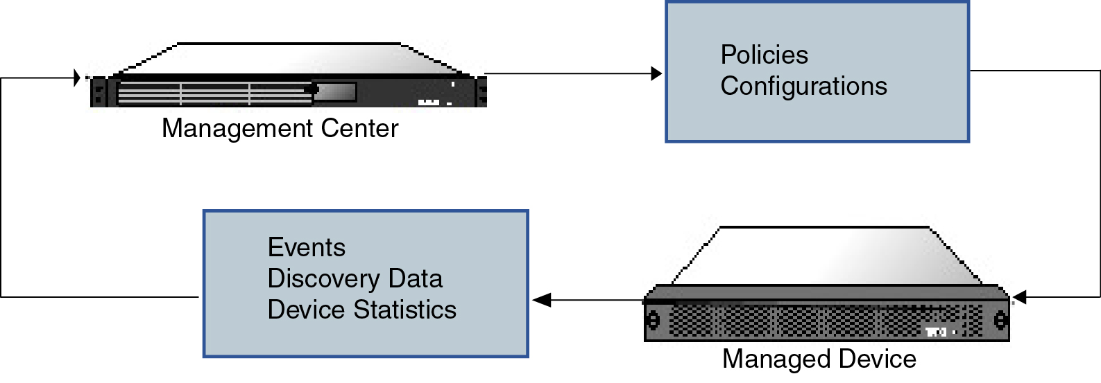

Diagram illustrating information passed between a management center and its managed devices. Policy and configuration information is passed from the management center to the managed devices. Events, discovery data, and device statistics are passed from the managed devices to the management center.

About the Management Connection

After you configure the device with the management center information and after you add the device to the management center, either the device or the management center can establish the management connection. Depending on initial setup:

  • Either the device or the management center can initiate.

  • Only the device can initiate.

  • Only the management center can initiate.

Initiation always originates with eth0 on the management center or with the lowest-numbered management interface on the device. Additional management interfaces are tried if the connection is not established. Multiple management interfaces on the management center let you connect to discrete networks or to segregate management and event traffic. However, the initiator does not choose the best interface based on the routing table.

Make sure the management connection is stable, without excessive packet loss, with at least 5 Mbps throughput. By default, the management connection uses TCP port 8305 (this port is configurable). If you place another threat defense between devices and the management center, to prevent potential management disruption, be sure to exempt management traffic from deep inspection by applying a prefilter policy for it.


Note


The management connection is a secure, TLS-1.3-encrypted communication channel between itself and the device. You do not need to run this traffic over an additional encrypted tunnel such as Site-to-Site VPN for security purposes. If the VPN goes down, for example, you will lose your management connection, so we recommend a simple management path.


Beyond Policies and Events

In addition to deploying policies to devices and receiving events from them, you can also perform other device-related tasks on the management center.

Backing Up a Device

You cannot backup a physical managed device from the FTD CLI. To back up configuration data, and, optionally, unified files, perform a backup of the device using the management center that is managing the device.

To back up event data, perform a backup of the management center that is managing the device.

Updating Devices

From time to time, Cisco releases updates to the Firepower System, including:

  • intrusion rule updates, which may contain new and updated intrusion rules

  • vulnerability database (VDB) updates

  • geolocation updates

  • software patches and updates

You can use the management center to install an update on the devices it manages.

About Device Management Interfaces

Each device includes a single dedicated Management interface for communicating with the management center. You can optionally configure the device to use a data interface for management instead of the dedicated Management interface.

You can perform initial setup on the management interface, or on the console port.

Management interfaces are also used to communicate with the Smart Licensing server, to download updates, and to perform other management functions.

Management and Event Interfaces on the Threat Defense

When you set up your device, you specify the management center IP address or hostname that you want to connect to, if known. In this case, the device initiates the connection, and both management and event traffic go to this address at initial registration. If the management center is not known, then the management center establishes the initial connection. In this case, it might initially connect from a different management center management interface than specified on the threat defense. Subsequent connections should use the management center management interface with the specified IP address.

If the management center has a separate event-only interface, the managed device sends subsequent event traffic to the management center event-only interface if the network allows. In addition, some managed-device models include an additional management interface that you can configure for event-only traffic. Note that if you configure a data interface for management, you cannot use separate management and event interfaces. If the event network goes down, then event traffic reverts to the regular management interfaces on the management center and/or on the managed device.

Using the Threat Defense Data Interface for Management

You can use either the dedicated Management interface or a regular data interface for communication with the management center. Manager access on a data interface is useful if you want to manage the threat defense remotely from the outside interface, or you do not have a separate management network. Moreover, using a data interface lets you configure a redundant secondary interface to take over management functions if the primary interface goes down.

Manager Access Requirements

Manager access from a data interface has the following requirements.

  • You can only enable manager access on a physical, data interface. You cannot use a subinterface or EtherChannel, nor can you create a subinterface on the manager access interface. You can also use the management center to enable manager access on a single secondary interface for redundancy.

  • This interface cannot be management-only.

  • Routed firewall mode only, using a routed interface.

  • PPPoE is not supported. If your ISP requires PPPoE, you will have to put a router with PPPoE support between the threat defense and the WAN modem.

  • The interface must be in the global VRF only.

  • SSH is not enabled by default for data interfaces, so you will have to enable SSH later using the management center. Because the Management interface gateway will be changed to be the data interfaces, you also cannot SSH to the Management interface from a remote network unless you add a static route for the Management interface using the configure network static-routes command. For threat defense virtual on Amazon Web Services, a console port is not available, so you should maintain your SSH access to the Management interface: add a static route for Management before you continue with your configuration. Alternatively, be sure to finish all CLI configuration (including the configure manager add command) before you configure the data interface for manager access and you are disconnected.

  • You cannot use separate management and event-only interfaces.

  • Clustering is not supported. You must use the Management interface in this case.

High Availability Requirements

When using a data interface with device high availability, see the following requirements.

  • Use the same data interface on both devices for manager access.

  • Redundant manager access data interface is not supported.

  • You cannot use DHCP; only a static IP address is supported. Features that rely on DHCP cannot be used, including DDNS and zero-touch provisioning.

  • Have different static IP addresses in the same subnet.

  • Use either IPv4 or IPv6; you cannot set both.

  • Use the same manager configuration (configure manager add command) to ensure that the connectivity is the same.

  • You cannot use the data interface as the failover or state link.

Management Interface Support Per Device Model

See the hardware installation guide for your model for the management interface locations.


Note


For the Firepower 4100/9300, the MGMT interface is for chassis management, not for threat defense logical device management. You must configure a separate interface to be of type mgmt (and/or firepower-eventing), and then assign it to the threat defense logical device.


See the following table for supported management interfaces on each managed device model.

Table 1. Management Interface Support on Managed Devices

Model

Management Interface

Optional Event Interface

Firepower 1000

management0

Note


management0 is the internal name of the Management 1/1 interface.

No Support

Secure Firewall 1200

management0

Note


management0 is the internal name of the Management 1/1 interface.

No Support

Secure Firewall 3100

management0

Note


management0 is the internal name of the Management 1/1 interface.

No Support

Secure Firewall 4200

management0

Note


management0 is the internal name of the Management 1/1 interface.

management1

Note


management1 is the internal name of the Management 1/2 interface.

Firepower 4100 and 9300

management0

Note


management0 is the internal name of this interface, regardless of the physical interface ID.

management1

Note


management1 is the internal name of this interface, regardless of the physical interface ID.

ISA 3000

br1

Note


br1 is the internal name of the Management 1/1 interface.

No support

Secure Firewall Threat Defense Virtual

eth0

No support

Network Routes on Device Management Interfaces

Management interfaces (including event-only interfaces) support only static routes to reach remote networks. When you set up your managed device, the setup process creates a default route to the gateway IP address that you specify. You cannot delete this route; you can only modify the gateway address.


Note


The routing for management interfaces is completely separate from routing that you configure for data interfaces. If you configure a data interface for management instead of using the dedicated Management interface, traffic is routed over the backplane to use the data routing table. The information in this section does not apply.


You can configure multiple management interfaces on some platforms (a management interface and an event-only interface). The default route does not include an egress interface, so the interface chosen depends on the gateway address you specify, and which interface's network the gateway belongs to. In the case of multiple interfaces on the default network, the device uses the lower-numbered interface as the egress interface.

At least one static route is recommended per management interface to access remote networks. We recommend placing each interface on a separate network to avoid potential routing problems, including routing problems from other devices to the threat defense.


Note


The interface used for management connections is not determined by the routing table. Connections are always tried using the lowest-numbered interface first.


NAT Environments

Network address translation (NAT) is a method of transmitting and receiving network traffic through a router that involves reassigning the source or destination IP address. The most common use for NAT is to allow private networks to communicate with the internet. Static NAT performs a 1:1 translation, which does not pose a problem for management center communication with devices, but port address translation (PAT) is more common. PAT lets you use a single public IP address and unique ports to access the public network; these ports are dynamically assigned as needed, so you cannot initiate a connection to a device behind a PAT router.

Normally, you need both IP addresses (along with a registration key) for both routing purposes and for authentication: the management center specifies the device IP address when you add a device, and the device specifies the management center IP address. However, if you only know one of the IP addresses, which is the minimum requirement for routing purposes, then you must also specify a unique NAT ID on both sides of the connection to establish trust for the initial communication and to look up the correct registration key. The management center and device use the registration key and NAT ID (instead of IP addresses) to authenticate and authorize for initial registration.

For example, you add a device to the management center, and you do not know the device IP address (for example, the device is behind a PAT router), so you specify only the NAT ID and the registration key on the management center; leave the IP address blank. On the device, you specify the management center IP address, the same NAT ID, and the same registration key. The device registers to the management center's IP address. At this point, the management center uses the NAT ID instead of IP address to authenticate the device.

Although the use of a NAT ID is most common for NAT environments, you might choose to use the NAT ID to simplify adding many devices to the management center. On the management center, specify a unique NAT ID for each device you want to add while leaving the IP address blank, and then on each device, specify both the management center IP address and the NAT ID. Note: The NAT ID must be unique per device.

The following example shows three devices behind a PAT IP address. In this case, specify a unique NAT ID per device on both the management center and the devices, and specify the management center IP address on the devices.
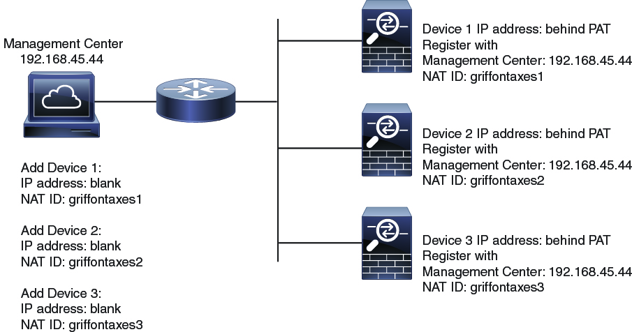
Figure 1. NAT ID for Managed Devices Behind PAT
NAT ID for Managed Devices Behind PAT

The following example shows the management center behind a PAT IP address. In this case, specify a unique NAT ID per device on both the management center and the devices, and specify the device IP addresses on the management center.
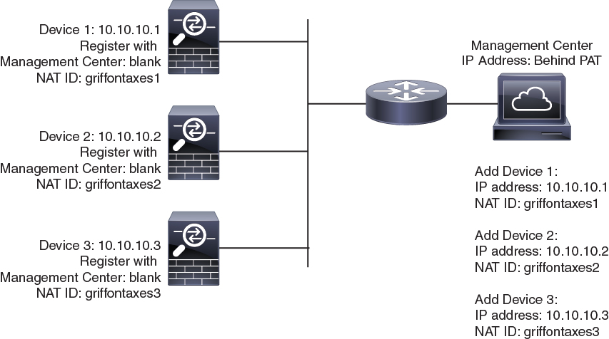
Figure 2. NAT ID for Management Center Behind PAT
NAT ID for management center Behind PAT

Management and Event Traffic Channel Examples


Note


If you use a data interface for management on a threat defense, you cannot use separate management and event interfaces for that device.


The following example shows the management center and managed devices using only the default management interfaces.
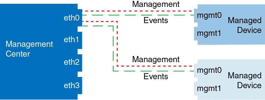
Figure 3. Single Management Interface on the Secure Firewall Management Center

The following example shows the management center using separate management interfaces for devices; and each managed device using 1 management interface.

Figure 4. Multiple Management Interfaces on the Secure Firewall Management Center

The following example shows the management center and managed devices using a separate event interface.
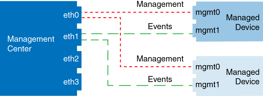
Figure 5. Separate Event Interface on the Secure Firewall Management Center and Managed Devices

The following example shows a mix of multiple management interfaces and a separate event interface on the management center and a mix of managed devices using a separate event interface, or using a single management interface.
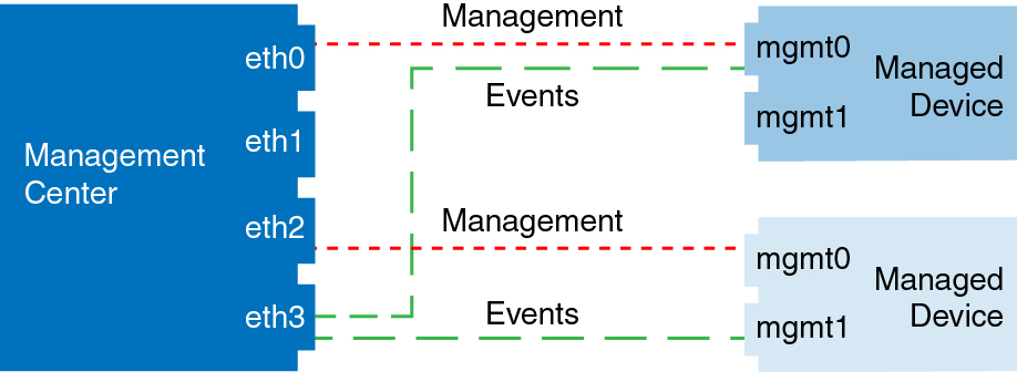
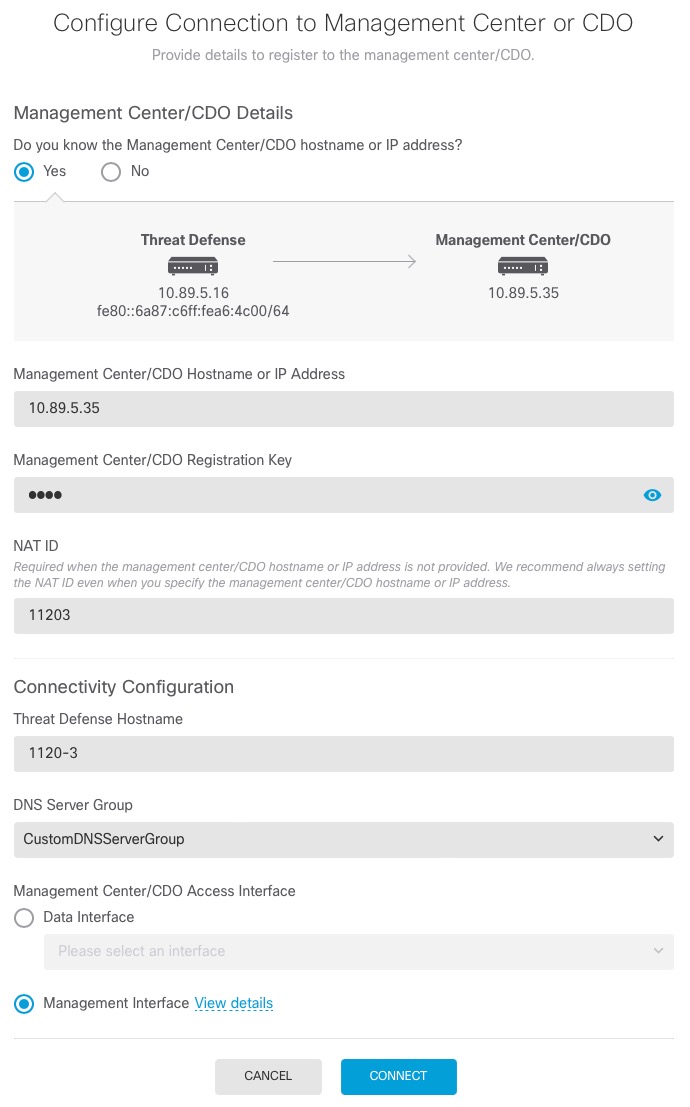
Figure 6. Mixed Management and Event Interface Usage

Requirements and Prerequisites for Device Management

Supported Domains

The domain in which the device resides.

User Roles

  • Admin

  • Network Admin

Management Connection

Make sure the management connection is stable, without excessive packet loss, with at least 5Mbps throughput.

Log Into the Command Line Interface on the Device

You can log directly into the command line interface on threat defense devices. If this is your first time logging in, complete the initial setup process using the default admin user; see Complete the Threat Defense Initial Configuration Using the CLI.


Note


If a user makes three consecutive failed attempts to log into the CLI via SSH, the system terminates the SSH connection.


Before you begin

Create additional user accounts that can log into the CLI using the configure user add command.

Procedure


Step 1

Connect to the threat defense CLI, either from the console port or using SSH.

You can SSH to the management interface of the threat defense device. You can also connect to the address on a data interface if you open the interface for SSH connections. SSH access to data interfaces is disabled by default. See SSH Access to allow SSH connections to specific data interfaces.

For physical devices, you can directly connect to the console port on the device. See the hardware guide for your device for more information about the console cable. Use the following serial settings:

  • 9600 baud

  • 8 data bits

  • No parity

  • 1 stop bit

The CLI on the console port is FXOS (with the exception of the ISA 3000, where it is the regular threat defense CLI). Use the threat defense CLI for basic configuration, monitoring, and normal system troubleshooting. See the FXOS documentation for information on FXOS commands.

For a chassis in multi-instance mode, you can connect to FXOS on the console port, or you can enable SSH for the Management interface according to Configure SSH and SSH Access List. SSH is disabled by default.

Step 2

Log in with the admin username and password.

Example:


firepower login: admin
Password:
Last login: Thu May 16 14:01:03 UTC 2019 on ttyS0
Successful login attempts for user 'admin' : 1

firepower# 

Step 3

If you used the console port, access the threat defense CLI.

connect ftd

Multi-instance mode:

connect ftd name

To view the instance names, enter the command without a name.

Note


This step does not apply to the ISA 3000.

Example:


firepower# connect ftd
>

Step 4

At the CLI prompt (>), use any of the commands allowed by your level of command line access.

To return to FXOS on the console port, enter exit .

Step 5

(Optional) If you used SSH, you can connect to FXOS.

connect fxos

To return to the threat defense CLI, enter exit .

Step 6

(Optional) Access the diagnostic CLI:

system support diagnostic-cli

Use this CLI for advanced troubleshooting. This CLI includes additional show and other commands.

This CLI has two sub-modes: user EXEC and privileged EXEC mode. More commands are available in privileged EXEC mode. To enter privileged EXEC mode, enter the enable command; press enter without entering a password when prompted.

Example:


> system support diagnostic-cli
firepower> enable
Password:
firepower#

To return to the regular CLI, type Ctrl-a, d.


Complete the Threat Defense Initial Configuration for Manual Registration

You can complete the threat defense initial configuration using the CLI or the device manager for all models except for the Firepower 4100/9300. For the Firepower 4100/9300, you complete initial configuration when you deploy the logical device. See Logical Devices on the Firepower 4100/9300.

For zero-touch provisioning (serial number registration), you should not log into the device or perform initial setup. See Add a Device Using the Serial Number (Zero-Touch Provisioning).

Complete the Threat Defense Initial Configuration Using the Device Manager

When you use the device manager for initial setup, the following interfaces are preconfigured in addition to the Management interface and manager access settings:

  • Ethernet 1/1—"outside", IP address from DHCP, IPv6 autoconfiguration

  • Ethernet 1/2 (or for the Firepower 1010 and Secure Firewall 1210/1220, the VLAN1 interface)— "inside", 192.168.95.1/24

  • Default route—Obtained through DHCP on the outside interface

Note that other settings, such as the DHCP server on inside, access control policy, or security zones, are not configured.

If you perform additional interface-specific configuration within device manager before registering with the management center, then that configuration is preserved.

When you use the CLI, only the Management interface and manager access settings are retained (for example, the default inside interface configuration is not retained).

  • The Secure Firewall 4200 does not support the device manager. You need to use the CLI procedure: Complete the Threat Defense Initial Configuration Using the CLI.

  • This procedure does not apply for CDO-managed devices for which you want to use an on-prem management center for analytics only. The device manager configuration is meant to configure the primary manager. See Complete the Threat Defense Initial Configuration Using the CLI for more information about configuring the device for analytics.

  • This procedure applies to all other devices except for the Firepower 4100/9300 and the ISA 3000. You can use the device manager to onboard these devices to the management center, but because they have different default configurations than other platforms, the details in this procedure may not apply to these platforms.

Procedure


Step 1

Log into the device manager.

  1. Enter the following URL in your browser.

    • Inside—https://192.168.95.1 .

    • Management—https://management_ip . The Management interface is a DHCP client, so the IP address depends on your DHCP server. You will have to set the Management IP address to a static address as part of this procedure, so we recommend that you use the inside interface so you do not become disconnected.

  2. Log in with the username admin, and the default password Admin123.

  3. You are prompted to read and accept the End User License Agreement and change the admin password.

Step 2

Use the setup wizard when you first log into the device manager to complete the initial configuration. You can optionally skip the setup wizard by clicking Skip device setup at the bottom of the page.

After you complete the setup wizard, in addition to the default configuration for the inside interface, you will have configuration for an outside (Ethernet1/1) interface that will be maintained when you switch to the management center management.

  1. Configure the following options for the outside and management interfaces, and click Next.

    1. Outside Interface Address—This interface is typically the internet gateway, and might be used as your manager access interface. You cannot select an alternative outside interface during initial device setup. The first data interface is the default outside interface.

      If you want to use a different interface from outside (or inside) for manager access, you will have to configure it manually after completing the setup wizard.

      Configure IPv4—The IPv4 address for the outside interface. You can use DHCP or manually enter a static IP address, subnet mask, and gateway. You can also select Off to not configure an IPv4 address. You cannot configure PPPoE using the setup wizard. PPPoE may be required if the interface is connected to a DSL modem, cable modem, or other connection to your ISP, and your ISP uses PPPoE to provide your IP address. You can configure PPPoE after you complete the wizard.

      Configure IPv6—The IPv6 address for the outside interface. You can use DHCP or manually enter a static IP address, prefix, and gateway. You can also select Off to not configure an IPv6 address.

    2. Management Interface

      You will not see Management Interface settings if you performed initial setup at the CLI.

      The Management interface settings are used even if you enable manager access on a data interface. For example, the management traffic that is routed over the backplane through the data interface will resolve FQDNs using the Management interface DNS servers, and not the data interface DNS servers.

      DNS Servers—The DNS server for the system's management address. Enter one or more addresses of DNS servers for name resolution. The default is the OpenDNS public DNS servers. If you edit the fields and want to return to the default, click Use OpenDNS to reload the appropriate IP addresses into the fields.

      Firewall Hostname—The hostname for the system's management address.

  2. Configure the Time Setting (NTP) and click Next.

    1. Time Zone—Select the time zone for the system.

    2. NTP Time Server—Select whether to use the default NTP servers or to manually enter the addresses of your NTP servers. You can add multiple servers to provide backups.

  3. Select Start 90 day evaluation period without registration.

    Do not register the threat defense with the Smart Software Manager; all licensing is performed on the management center.

  4. Click Finish.

  5. You are prompted to choose Cloud Management or Standalone. For management center management, choose Standalone, and then Got It.

Step 3

(Might be required) Configure the Management interface.

You may need to change the Management interface configuration, even if you intend to use a data interface for manager access. You will have to reconnect to the device manager if you were using the Management interface for the device manager connection.

  • Data interface for manager access—The Management interface must have the gateway set to data interfaces. By default, the Management interface receives an IP address and gateway from DHCP. If you do not receive a gateway from DHCP (for example, you did not connect this interface to a network), then the gateway will default to data interfaces, and you do not need to configure anything. If you did receive a gateway from DHCP, then you need to instead configure this interface with a static IP address and set the gateway to data interfaces.

  • Management interface for manager access—If you want to configure a static IP address, be sure to also set the default gateway to be a unique gateway instead of the data interfaces. If you use DHCP, then you do not need to configure anything assuming you successfully get the gateway from DHCP.

Step 4

If you want to configure additional interfaces, including an interface other than outside or inside that you want to use for manager access, choose Device, and then click the link in the Interfaces summary.

Other device manager configuration will not be retained when you register the device to management center.

Step 5

Choose Device > System Settings > Central Management, and click Proceed to set up the management center management.

Step 6

Configure the Management Center/CDO Details.

Figure 7. Management Center/CDO Details
Management Center/CDO Details
  1. For Do you know the Management Center/CDO hostname or IP address, click Yes if you can reach the management center using an IP address or hostname, or No if the management center is behind NAT or does not have a public IP address or hostname.

    At least one of the devices, either the management center or the threat defense device, must have a reachable IP address to establish the two-way, TLS-1.3-encrypted communication channel between the two devices.

  2. If you chose Yes, then enter the Management Center/CDO Hostname/IP Address.

  3. Specify the Management Center/CDO Registration Key.

    This key is a one-time registration key of your choice that you will also specify on the management center when you register the threat defense device. The registration key must not exceed 37 characters. Valid characters include alphanumerical characters (A–Z, a–z, 0–9) and the hyphen (-). This ID can be used for multiple devices registering to the management center.

  4. Specify a NAT ID.

    This ID is a unique, one-time string of your choice that you will also specify on the management center. This field is required if you only specify the IP address on one of the devices; but we recommend that you specify the NAT ID even if you know the IP addresses of both devices. The NAT ID must not exceed 37 characters. Valid characters include alphanumerical characters (A–Z, a–z, 0–9) and the hyphen (-). This ID cannot be used for any other devices registering to the management center. The NAT ID is used in combination with the IP address to verify that the connection is coming from the correct device; only after authentication of the IP address/NAT ID will the registration key be checked.

Step 7

Configure the Connectivity Configuration.

  1. Specify the FTD Hostname.

    If you use a data interface for the Management Center/CDO Access Interface access, then this FQDN will be used for this interface.

  2. Specify the DNS Server Group.

    Choose an existing group, or create a new one. The default DNS group is called CiscoUmbrellaDNSServerGroup, which includes the OpenDNS servers.

    If you intend to choose a data interface for the Management Center/CDO Access Interface, then this setting sets the data interface DNS server. The Management DNS server that you set with the setup wizard is used for management traffic. The data DNS server is used for DDNS (if configured) or for security policies applied to this interface. You are likely to choose the same DNS server group that you used for Management, because both management and data traffic reach the DNS server through the outside interface.

    On the management center, the data interface DNS servers are configured in the Platform Settings policy that you assign to this threat defense device. When you add the threat defense device to the management center, the local setting is maintained, and the DNS servers are not added to a Platform Settings policy. However, if you later assign a Platform Settings policy to the threat defense device that includes a DNS configuration, then that configuration will overwrite the local setting. We suggest that you actively configure the DNS Platform Settings to match this setting to bring the management center and the threat defense device into sync.

    Also, local DNS servers are only retained by the management center if the DNS servers were discovered at initial registration.

    If you intend to choose the Management interface for the CDOFMC Access Interface, then this setting configures the Management DNS server.

  3. For the Management Center/CDO Access Interface, choose any configured interface.

    You can change the manager interface after you register the threat defense device to the management center, to either the Management interface or another data interface.

Step 8

(Optional) If you chose a data interface, and it was not the outside interface, then add a default route.

You will see a message telling you to check that you have a default route through the interface. If you chose outside, you already configured this route as part of the setup wizard. If you chose a different interface, then you need to manually configure a default route before you connect to the management center.

If you chose the Management interface, then you need to configure the gateway to be a unique gateway before you can proceed on this screen.

Step 9

(Optional) If you chose a data interface, click Add a Dynamic DNS (DDNS) method.

DDNS ensures the management center can reach the threat defense device at its Fully-Qualified Domain Name (FQDN) if the IP address changes. See Device > System Settings > DDNS Service to configure DDNS.

If you configure DDNS before you add the threat defense device to the management center, the threat defense device automatically adds certificates for all of the major CAs from the Cisco Trusted Root CA bundle so that the threat defense device can validate the DDNS server certificate for the HTTPS connection. Threat Defense supports any DDNS server that uses the DynDNS Remote API specification (https://help.dyn.com/remote-access-api/).

DDNS is not supported when using the Management interface for manager access.

Step 10

Click Connect. The Registration Status dialog box shows the current status of the switch to the management center. After the Saving Management Center/CDO Registration Settings step, go to the management center, and add the firewall.

If you want to cancel the switch to the management center, click Cancel Registration. Otherwise, do not close the device manager browser window until after the Saving Management Center/CDO Registration Settings step. If you do, the process will be paused, and will only resume when you reconnect to the device manager.

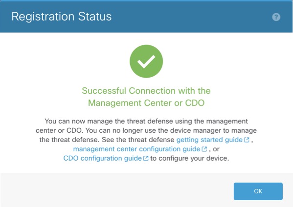
If you remain connected to the device manager after the Saving Management Center/CDO Registration Settings step, you will eventually see the Successful Connection with Management Center or CDO dialog box, after which you will be disconnected from the device manager.

Figure 8. Successful Connection
Successful Connection

Complete the Threat Defense Initial Configuration Using the CLI

Connect to the threat defense CLI to perform initial setup, including setting the Management IP address, gateway, and other basic networking settings using the setup wizard. The dedicated Management interface is a special interface with its own network settings. If you do not want to use the Management interface for manager access, you can use the CLI to configure a data interface instead. You will also configure management center communication settings. When you perform initial setup using the device manager, all interface configuration completed in the device manager is retained when you switch to the management center for management, in addition to the Management interface and manager access interface settings. Note that other default configuration settings, such as the access control policy, are not retained.

This procedure applies to all models except for the Firepower 4100/9300. To deploy a logical device and complete initial configuration on the Firepower 4100/9300, see Logical Devices on the Firepower 4100/9300.

Procedure


Step 1

Connect to the threat defense CLI, either from the console port or using SSH to the Management interface, which obtains an IP address from a DHCP server by default. If you intend to change the network settings, we recommend using the console port so you do not get disconnected.

(Firepower and Secure Firewall hardware models) The console port connects to the FXOS CLI. The SSH session connects directly to the threat defense CLI.

Step 2

Log in with the username admin and the password Admin123.

(Firepower and Secure Firewall hardware models) At the console port, you connect to the FXOS CLI. The first time you log in to FXOS, you are prompted to change the password. This password is also used for the threat defense login for SSH.

Note


If the password was already changed, and you do not know it, you must reimage the device to reset the password to the default.

For Firepower and Secure Firewall hardware, see the Reimage Procedures in the Cisco FXOS Troubleshooting Guide for the Firepower 1000/2100 and Secure Firewall 3100/4200 with Threat Defense .

For the ISA 3000, see the Cisco Secure Firewall ASA and Secure Firewall Threat Defense Reimage Guide.

Example:


firepower login: admin
Password: Admin123
Successful login attempts for user 'admin' : 1

[...]

Hello admin. You must change your password.
Enter new password: ********
Confirm new password: ********
Your password was updated successfully.

[...]

firepower# 

Step 3

(Firepower and Secure Firewall hardware models) If you connected to FXOS on the console port, connect to the threat defense CLI.

connect ftd

Example:


firepower# connect ftd
>

Step 4

The first time you log in to the threat defense, you are prompted to accept the End User License Agreement (EULA) and, if using an SSH connection, to change the admin password. You are then presented with the CLI setup script.

Note


You cannot repeat the CLI setup wizard unless you clear the configuration; for example, by reimaging. However, all of these settings can be changed later at the CLI using configure network commands. See the threat defense command reference.

Defaults or previously entered values appear in brackets. To accept previously entered values, press Enter.

Note


The Management interface settings are used even when you enable manager access on a data interface. For example, the management traffic that is routed over the backplane through the data interface will resolve FQDNs using the Management interface DNS servers, and not the data interface DNS servers.

See the following guidelines:

  • Do you want to configure IPv4? and/or Do you want to configure IPv6?—Enter y for at least one of these types of addresses.

  • Enter the IPv4 default gateway for the management interface and/or Enter the IPv6 gateway for the management interface—If you want to use a data interface for manager access instead of the Management interface, choose manual. Although you do not plan to use the Management interface, you must set an IP address, for example, a private address. Make sure this interface is on a different subnet from the manager access interface to prevent routing issues. You cannot configure a data interface for management if the management interface is set to DHCP, because the default route, which must be data-interfaces (see the next bullet), might be overwritten with one received from the DHCP server.

  • Enter the IPv4 default gateway for the management interface and/or Configure IPv6 via DHCP, router, or manually?If you want to use a data interface for manager access instead of the management interface, set the gateway to be data-interfaces. This setting forwards management traffic over the backplane so it can be routed through the manager access data interface. If you want to use the Management interface for manager access, you should set a gateway IP address on the Management 1/1 network.

  • If your networking information has changed, you will need to reconnect—If you are connected with SSH but you change the IP address at initial setup, you will be disconnected. Reconnect with the new IP address and password. Console connections are not affected.

  • Manage the device locally?—Enter no to use the management center. A yes answer means you will use Secure Firewall device manager instead.

  • Configure firewall mode?—We recommend that you set the firewall mode at initial configuration. Changing the firewall mode after initial setup erases your running configuration. Note that data interface manager access is only supported in routed firewall mode.

Example:


You must accept the EULA to continue.
Press <ENTER> to display the EULA:
Cisco General Terms
[...]

Please enter 'YES' or press <ENTER> to AGREE to the EULA: 


System initialization in progress.  Please stand by.
You must configure the network to continue.
Configure at least one of IPv4 or IPv6 unless managing via data interfaces.
Do you want to configure IPv4? (y/n) [y]:
Do you want to configure IPv6? (y/n) [y]: n
Configure IPv4 via DHCP or manually? (dhcp/manual) [manual]:
Enter an IPv4 address for the management interface [192.168.45.61]: 10.89.5.17
Enter an IPv4 netmask for the management interface [255.255.255.0]: 255.255.255.192
Enter the IPv4 default gateway for the management interface [data-interfaces]: 10.89.5.1
Enter a fully qualified hostname for this system [firepower]: 1010-3
Enter a comma-separated list of DNS servers or 'none' [208.67.222.222,208.67.220.220,2620:119:35::35]:
Enter a comma-separated list of search domains or 'none' []: cisco.com
If your networking information has changed, you will need to reconnect.
Disabling IPv6 configuration: management0
Setting DNS servers: 208.67.222.222,208.67.220.220,2620:119:35::35
Setting DNS domains:cisco.com
Setting hostname as 1010-3
Setting static IPv4: 10.89.5.17 netmask: 255.255.255.192 gateway: 10.89.5.1 on management0
Updating routing tables, please wait...
All configurations applied to the system. Took 3 Seconds.
Saving a copy of running network configuration to local disk.
For HTTP Proxy configuration, run 'configure network http-proxy'

Manage the device locally? (yes/no) [yes]: no
DHCP server is already disabled
DHCP Server Disabled
Configure firewall mode? (routed/transparent) [routed]:
Configuring firewall mode ...


Device is in OffBox mode - disabling/removing port 443 from iptables.
Update policy deployment information
    - add device configuration
    - add network discovery
    - add system policy

You can register the sensor to a Firepower Management Center and use the
Firepower Management Center to manage it. Note that registering the sensor
to a Firepower Management Center disables on-sensor Firepower Services
management capabilities.

When registering the sensor to a Firepower Management Center, a unique
alphanumeric registration key is always required.  In most cases, to register
a sensor to a Firepower Management Center, you must provide the hostname or
the IP address along with the registration key.
'configure manager add [hostname | ip address ] [registration key ]'

However, if the sensor and the Firepower Management Center are separated by a
NAT device, you must enter a unique NAT ID, along with the unique registration
key.
'configure manager add DONTRESOLVE [registration key ] [ NAT ID ]'

Later, using the web interface on the Firepower Management Center, you must
use the same registration key and, if necessary, the same NAT ID when you add
this sensor to the Firepower Management Center.
>

Step 5

Identify the management center that will manage this threat defense.

configure manager add {hostname | IPv4_address | IPv6_address | DONTRESOLVE} reg_key [nat_id] [display_name]

Note


If you are using CDO for management, use the CDO-generated configure manager add command for this step.

  • {hostname | IPv4_address | IPv6_address | DONTRESOLVE}—Specifies either the FQDN or IP address of the management center. If the management center is not directly addressable, use DONTRESOLVE and also specify the nat_id. At least one of the devices, either the management center or the threat defense, must have a reachable IP address to establish the two-way, TLS-1.3-encrypted communication channel between the two devices. If you specify DONTRESOLVE in this command, then the FTD must have a reachable IP address or hostname.

  • reg_key—Specifies a one-time registration key of your choice that you will also specify on the management center when you register the threat defense. The registration key must not exceed 37 characters. Valid characters include alphanumerical characters (A–Z, a–z, 0–9) and the hyphen (-).

  • nat_id—Specifies a unique, one-time string of your choice that you will also specify on the management center when you register the threat defense when one side does not specify a reachable IP address or hostname. For example, it is required if you set the management center to DONTRESOLVE. It is also required if you use the data interface for management, even if you specify IP addresses. The NAT ID must not exceed 37 characters. Valid characters include alphanumerical characters (A–Z, a–z, 0–9) and the hyphen (-). This ID cannot be used for any other devices registering to the management center.

    Note


    If you use a data interface for management, then you must specify the NAT ID on both the threat defense and management center, even if you specify both IP addresses.

  • display_name —Provide a display name for showing this manager with the show managers command. This option is useful if you are identifying CDO as the primary manager and an on-prem management center for analytics only. If you don't specify this argument, the firewall auto-generates a display name using one of the following methods:

    • hostname | IP_address (if you don't use the DONTRESOLVE keyword)

    • manager-timestamp

Example:


> configure manager add MC.example.com 123456
Manager successfully configured.

Example:

If the management center is behind a NAT device, enter a unique NAT ID along with the registration key, and specify DONTRESOLVE instead of the hostname, for example:


> configure manager add DONTRESOLVE regk3y78 natid90
Manager successfully configured.

Example:

If the threat defense is behind a NAT device, enter a unique NAT ID along with the management center IP address or hostname, for example:


> configure manager add 10.70.45.5 regk3y78 natid56
Manager successfully configured.

Step 6

If you are using CDO as your primary manager and want to use an on-prem management center for analytics only, identify the on-prem management center.

configure manager add {hostname | IPv4_address | IPv6_address | DONTRESOLVE} reg_key [nat_id] [display_name]

Example:

The following example uses the generated command for CDO with a CDO-generated display name and then specifies an on-prem management center for analytics only with the "analytics-FMC" display name.


> configure manager add account1.app.us.cdo.cisco.com KPOOP0rgWzaHrnj1V5ha2q5Rf8pKFX9E
Lzm1HOynhVUWhXYWz2swmkj2ZWsN3Lb account1.app.us.cdo.cisco.com
Manager successfully configured.
> configure manager add 10.70.45.5 regk3y78 natid56 analytics-FMC
Manager successfully configured.

Step 7

(Optional) Configure a data interface for manager access.

configure network management-data-interface

You are then prompted to configure basic network settings for the data interface.

Note


You should use the console port when using this command. If you use SSH to the Management interface, you might get disconnected and have to reconnect to the console port. See below for more information about SSH usage.

See the following details for using this command. See also Using the Threat Defense Data Interface for Management.

  • The original Management interface cannot use DHCP if you want to use a data interface for management. If you did not set the IP address manually during initial setup, you can set it now using the configure network {ipv4 | ipv6} manual command. Make sure this interface is on a different subnet from the manager access interface to prevent routing issues. If you did not already set the Management interface gateway to data-interfaces, this command will set it now.

  • When you add the threat defense to the management center, the management center discovers and maintains the interface configuration, including the following settings: interface name and IP address, static route to the gateway, DNS servers, and DDNS server. For more information about the DNS server configuration, see below. In the management center, you can later make changes to the manager access interface configuration, but make sure you don't make changes that can prevent the threat defense or management center from re-establishing the management connection. If the management connection is disrupted, the threat defense includes the configure policy rollback command to restore the previous deployment.

  • DDNS ensures the management center can reach the threat defense at its Fully-Qualified Domain Name (FQDN) if the IP address changes. If you configure a DDNS server update URL, the threat defense automatically adds certificates for all of the major CAs from the Cisco Trusted Root CA bundle so that the threat defense can validate the DDNS server certificate for the HTTPS connection. The threat defense supports any DDNS server that uses the DynDNS Remote API specification (https://help.dyn.com/remote-access-api/).

  • This command sets the data interface DNS server. The Management DNS server that you set with the setup script (or using the configure network dns servers command) is used for management traffic. The data DNS server is used for DDNS (if configured) or for security policies applied to this interface.

    On the management center, the data interface DNS servers are configured in the Platform Settings policy that you assign to this threat defense. When you add the threat defense to the management center, the local setting is maintained, and the DNS servers are not added to a Platform Settings policy. However, if you later assign a Platform Settings policy to the threat defense that includes a DNS configuration, then that configuration will overwrite the local setting. We suggest that you actively configure the DNS Platform Settings to match this setting to bring the management center and the threat defense into sync.

    Also, local DNS servers are only retained by the management center if the DNS servers were discovered at initial registration. For example, if you registered the device using the Management interface, but then later configure a data interface using the configure network management-data-interface command, then you must manually configure all of these settings in the management center, including the DNS servers, to match the FTD configuration.

  • You can change the management interface after you register the threat defense to the management center, to either the Management interface or another data interface.

  • The FQDN that you set in the setup wizard will be used for this interface.

  • You can clear the entire device configuration as part of the command; you might use this option in a recovery scenario, but we do not suggest you use it for initial setup or normal operation.

  • To disable data management, enter the configure network management-data-interface disable command.

Example:


> configure network management-data-interface
Data interface to use for management: ethernet1/1
Specify a name for the interface [outside]:
IP address (manual / dhcp) [dhcp]:  
DDNS server update URL [none]: https://dwinchester:pa$$w0rd17@domains.example.com/nic/update?hostname=<h>&myip=<a>
Do you wish to clear all the device configuration before applying ? (y/n) [n]:

Configuration done with option to allow manager access from any network,
if you wish to change the manager access network 
use the 'client' option in the command 'configure network management-data-interface'.

Setting IPv4 network configuration.
Network settings changed.

> 

Example:


> configure network management-data-interface
Data interface to use for management: ethernet1/1
Specify a name for the interface [outside]: internet
IP address (manual / dhcp) [dhcp]: manual
IPv4/IPv6 address: 10.10.6.7
Netmask/IPv6 Prefix: 255.255.255.0
Default Gateway: 10.10.6.1
Comma-separated list of DNS servers [none]: 208.67.222.222,208.67.220.220
DDNS server update URL [none]:
Do you wish to clear all the device configuration before applying ? (y/n) [n]:

Configuration done with option to allow manager access from any network,
if you wish to change the manager access network
use the 'client' option in the command 'configure network management-data-interface'.

Setting IPv4 network configuration.
Network settings changed.

>

Step 8

(Optional) Limit data interface access to a manager on a specific network.

configure network management-data-interface client ip_address netmask

By default, all networks are allowed.


What to do next

Register your device to a management center.

Configure an Event Interface

You always need a management interface for management traffic. If your device has a second management interface, for example, the Firepower 4100/9300 and Secure Firewall 4200, you can enable it for event-only traffic.

Before you begin

To use a separate event interface, you also need to enable an event interface on the management center. See the Cisco Secure Firewall Management Center Administration Guide.

Procedure


Step 1

Enable the second management interface as an event-only interface.

configure network management-interface enable management1

configure network management-interface disable-management-channel management1

You can optionally disable events for the main management interface using the configure network management-interface disable-events-channel command. In either case, the device will try to send events on the event-only interface, and if that interface is down, it will send events on the management interface even if you disable the event channel.

You cannot disable both event and management channels on an interface.

Example:


> configure network management-interface enable management1
Configuration updated successfully

> configure network management-interface disable-management-channel management1
Configuration updated successfully

>

Step 2

Configure the IP address of the event interface.

The event interface can be on a separate network from the management interface, or on the same network.

  1. Configure the IPv4 address:

    configure network ipv4 manual ip_address netmask gateway_ip management1

    Note that the gateway_ip in this command is used to create the default route for the device, so you should enter the value you already set for the management0 interface. It does not create a separate static route for the eventing interface. If you are using an event-only interface on a different network from the management interface, we recommend that you create a static route separately for the event-only interface.

    Example:

    
    > configure network ipv4 manual 10.10.10.45 255.255.255.0 10.10.10.1 management1
    Setting IPv4 network configuration.
    Network settings changed.
    
    >
    
    
  2. Configure the IPv6 address:

    • Stateless autoconfiguration:

      configure network ipv6 router management1

      Example:

      
      > configure network ipv6 router management1
      Setting IPv6 network configuration.
      Network settings changed.
      
      >
      
      
    • Manual configuration:

      configure network ipv6 manual ip6_address ip6_prefix_length management1

      Example:

      
      > configure network ipv6 manual 2001:0DB8:BA98::3210 64 management1
      Setting IPv6 network configuration.
      Network settings changed.
      
      >


Step 3

Add a static route for the event-only interface if the management center is on a remote network; otherwise, all traffic will match the default route through the management interface.
configure network static-routes {ipv4 | ipv6}add management1 destination_ip netmask_or_prefix gateway_ip

For the default route, do not use this command; you can only change the default route gateway IP address when you use the configure network ipv4 or ipv6 commands (see, Step 2).

Example:


> configure network static-routes ipv4 add management1 192.168.6.0 255.255.255.0 10.10.10.1
Configuration updated successfully

> configure network static-routes ipv6 add management1 2001:0DB8:AA89::5110 64 2001:0DB8:BA98::3211
Configuration updated successfully

>

To display static routes, enter show network-static-routes (the default route is not shown):


> show network-static-routes
---------------[ IPv4 Static Routes ]---------------
Interface                 : management1
Destination               : 192.168.6.0
Gateway                   : 10.10.10.1
Netmask                   : 255.255.255.0
[…]


Manage Devices

The Devices > Device Management page provides you with range of information and options.

  • View By—View devices based on group, licenses, model, version, or access control policy.

  • Device State—View devices based on state (Error, Warning, etc.). You can click on a state icon to view the devices belonging to it. The number of devices belonging to the states are provided within brackets.

  • Search Device—Search for a device by device name, host name, or IP address.

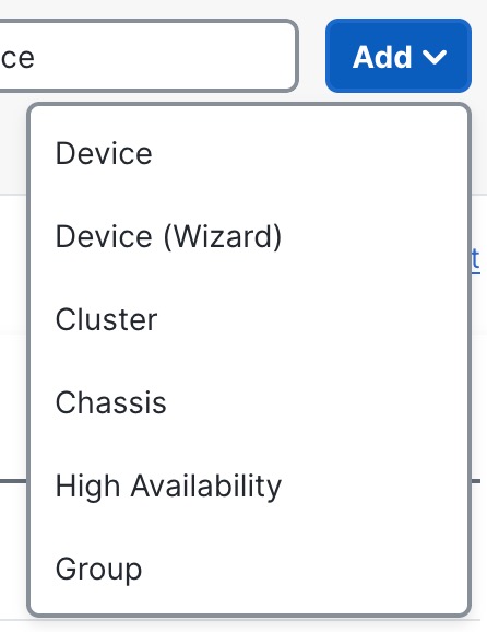
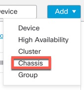
  • Add—Add devices and other manageable components.

    Figure 9. Add Menu
    Device Management Page
  • Columns—Click the column head to sort by that column.

    • Name

    • Model

    • Version

    • Chassis—For supported models, click Manage to bring up the integrated Chassis Manager. For the Firepower 4100/9300, the link cross-launches the chassis manager.

    • Licenses

    • Access Control Policy—Click on the link in the Access Control Policy column to view the policy that is deployed to the device.

    • Auto-Rollback—Shows whether auto-rollback of the configuration is enabled (auto rollback on icon) or disabled auto rollback off icon) if the deployment causes the management connection to go down. See Edit Deployment Settings.

  • Edit—For each device, use the Edit (edit icon) icon to edit the device settings.

    You can also just click on the device name or IP address.

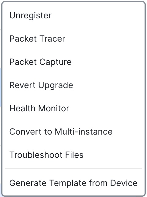
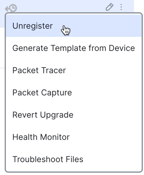
  • More—For each device, click the More (more icon) icon to execute other actions:

    Figure 10. More Menu
    Device Management Page
    • Unregister—To unregister the device.

    • Packet Tracer—To navigate to the packet tracer page for examining policy configuration on the device by injecting a model packet into the system.

    • Packet Capture—To navigate to the packet capture page, where, you can view the verdicts and actions the system takes while processing a packet.

    • Revert Upgrade—To revert the upgrade and configuration changes that were made after the last upgrade. This action results in restoring the device to the version that was before the upgrade.

    • Health Monitor—To navigate to the device's health monitoring page.

    • Convert to Multi-instance—For supported models, convert the chassis to multi-instance mode.

    • Troubleshoot Files—Generate troubleshooting files, where you can choose the type of data to be included in the report.

    • Generate Template from Device—Generate a new device template from a registered device. The new template has the same configuration as the device from which it is generated. You can generate a new device template from standalone and HA devices. However, if you generate a template from HA devices, the new template will not contain the failover configurations.

Add a Device Group

The management center allows you to group devices so you can easily deploy policies and install updates on multiple devices. You can expand and collapse the list of devices in the group.

If you add the primary device in a high-availability pair to a group, both devices are added to the group. If you break the high-availability pair, both devices remain in that group.

Procedure


Step 1

Choose Devices > Device Management.

Step 2

From the Add drop-down menu, choose Add Group.

To edit an existing group, click Edit (edit icon) for the group you want to edit.

Step 3

Enter a Name.

Step 4

Under Available Devices, choose one or more devices to add to the device group. Use Ctrl or Shift while clicking to choose multiple devices.

Step 5

Click Add to include the devices you chose in the device group.

Step 6

Optionally, to remove a device from the device group, click Delete (delete icon) next to the device you want to remove.

Step 7

Click OK to add the device group.


Register With the Management Center

The management center offers multiple methods to register your devices.

Registration Key Method

Add a device using a registration key that you specify in both the management center and the device initial configuration.

Add a Device Using a Registration Key

Use this procedure to add a single device to the management center using a registration key. If you plan to link devices for high availability, you must still use this procedure; see Add a High Availability Pair. For clustering, see the clustering chapter for your model.

You can also use this procedure to add a device that is managed by a cloud-delivered Firewall Management Center, and you want to use the on-prem management center for event logging and analytics purposes only.

To add a device using a template, see Add a Device Using a Registration Key—Device Template.

If you use management center high availability, add devices only to the active management center. Devices registered to the active management center are automatically registered to the standby.

Before you begin
  • Set up the device to be managed by the management center. See:

  • The management center must be registered to the Smart Software Manager. A valid evaluation license is sufficient, but if it expires, you will not be able to add new devices until you successfully register.

  • If you registered a device using IPv4 and want to convert it to IPv6, you must unregister and reregister the device.

Procedure

Step 1

Choose Devices > Device Management.

Step 2

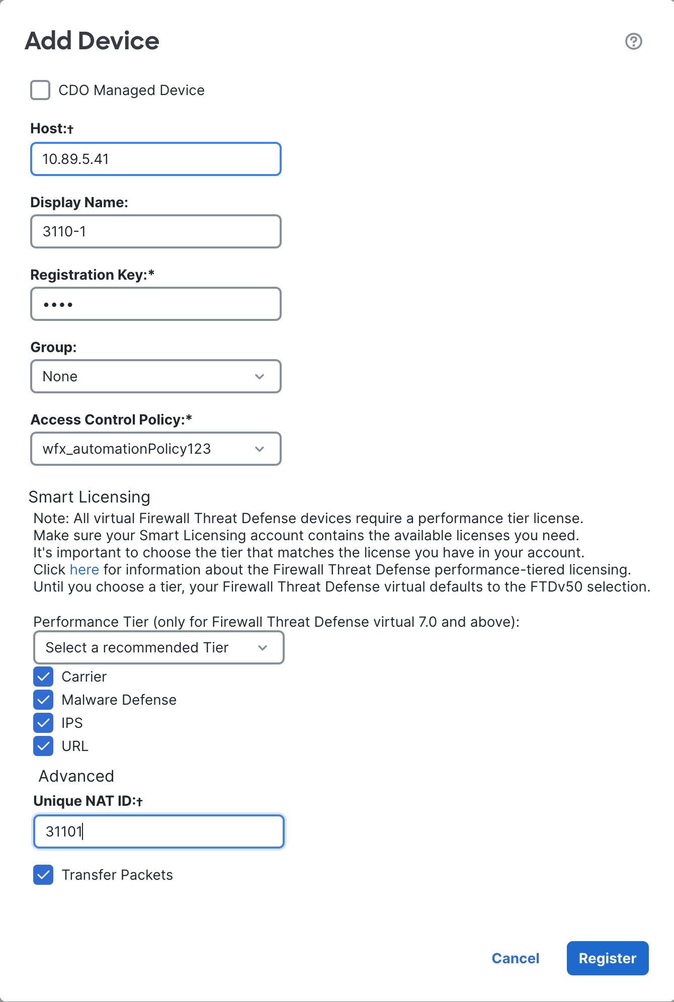
From the Add drop-down menu, choose Device.

Figure 11. Add Device Using a Registration Key
Add Device Using a Registration Key

Step 3

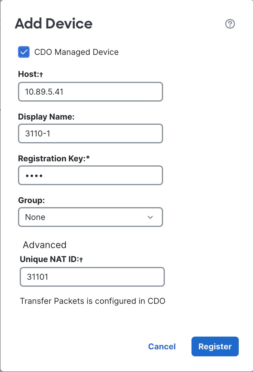
If you want to add a cloud-managed device to your on-prem management center for analytics only, check CDO Managed Device.

The system hides licensing and packet transfer settings because they are managed by CDO (formerly CDO). You can skip those steps.

Figure 12. Add Device for CDO
Add Device for CDO

Step 4

For the Host, enter the IP address or the hostname of the device you want to add. Leave this field blank if you don't know the device IP address (for example, it's behind NAT).

If you leave this field blank, the initial configuration on the device needs to include a reachable management center IP address or hostname plus the NAT ID. For more information, see NAT Environments.

Step 5

For the Display Name, enter a name for the device as you want it to display in the management center. You cannot change this name later.

Step 6

For the Registration Key, enter the same registration key in your initial configuration. The registration key is a one-time-use shared secret. The key can be up to 37-characters in length and include alphanumerical characters (A–Z, a–z, 0–9) and the hyphen (-). The registration key does not need to be unique per device.

Step 7

(Optional) Add the device to a device Group.

Step 8

Choose an initial Access Control Policy to deploy to the device upon registration, or create a new policy.

If the device is incompatible with the policy you choose, deploying will fail. This incompatibility could occur for multiple reasons, including licensing mismatches, model restrictions, passive vs inline issues, and other misconfigurations. After you resolve the issue that caused the failure, manually deploy configurations to the device.

Step 9

Choose licenses to apply to the device.

You can also apply licenses after you add the device, from the System > Licenses > Smart Licenses page.

For threat defense virtual, you must also select the Performance Tier. It’s important to choose the tier that matches the license you have in your account. Until you choose a tier, your device defaults to the FTDv50 selection. For more information about the performance-tiered license entitlements available for threat defense virtual, see FTDv Licenses in the Cisco Secure Firewall Management Center Administration Guide.

Note


If you are upgrading your threat defense virtual to Version 7.0+, you can choose FTDv - Variable to maintain your current license compliance.

Step 10

If you specified a NAT ID during initial configuration, in the Advanced section enter the same NAT ID for the Unique NAT ID.

The Unique NAT ID specifies a unique, one-time string of your choice that you will also specify on the device during initial configuration. It is required when one side does not specify a reachable IP address or hostname, for example if you left the Host field blank. Although technically optional, we recommend always specifying the NAT ID even when you know the IP addresses of both sides because it is required in certain situations. The ID can be up to 37-characters in length and include alphanumerical characters (A–Z, a–z, 0–9) and the hyphen (-). This ID cannot be used for any other devices registering to the management center.

Step 11

Check Transfer Packets so that for each intrusion event, the device transfers the packet to the management center for inspection.

This option is enabled by default. For each intrusion event, the device sends event information and the packet that triggered the event to the management center for inspection. If you disable it, only event information will be sent to the management center; the packet will not be sent.

Step 12

Click Register.

It may take up to two minutes for the management center to verify the device’s heartbeat and establish communication. If the registration succeeds, the device is added to the list. If it fails, you will see an error message. If the device fails to register, check the following items:

  • Ping—Access the device CLI, and ping the management center IP address using the following command:

    ping system ip_address

    If the ping is not successful, check your network settings using the show network command. If you need to change the device IP address, use the configure network {ipv4 | ipv6} manual command.

  • Registration key, NAT ID, and management center IP address—Make sure you are using the same registration key, and if used, NAT ID, on both devices. You can set the registration key and NAT ID on the device using the configure manager add command.

For more troubleshooting information, see https://cisco.com/go/fmc-reg-error.


Add a Device Using a Registration Key—Device Template

You can use a template to add a device, register the device with the management center and bring up the device with the given template configurations.

Before you begin

Create a device template according to Device Management Using Device Templates. You must specify any required variables and network object overrides for each device and ensure that model mapping is done for the target device model.

We recommend that you create a checklist to ensure that all configurations in the template have been entered correctly before applying the template on the device.

A sample checklist is given below.

  • Check version, model, operation modes.

  • Check list of variables and overrides.

  • Check sanity of variable and override values.

  • Check if the required Model Mappings exist.

  • Check if parallel device template operations are in progress.


Note


If you are adding a device that will be managed by a data interface, ensure that you configure the template to be compatible with the connectivity parameters of the device. For more information, see Configure a Template for Threat Defense Devices Managed Through the Data Interface.


Procedure

Step 1

Choose Devices > Device Management.

Step 2

From the Add drop-down menu, choose Device (Wizard).

Step 3

Click Registration Key, and then click Next.

Figure 13. Device Registration Method
Device Registration Method

Step 4

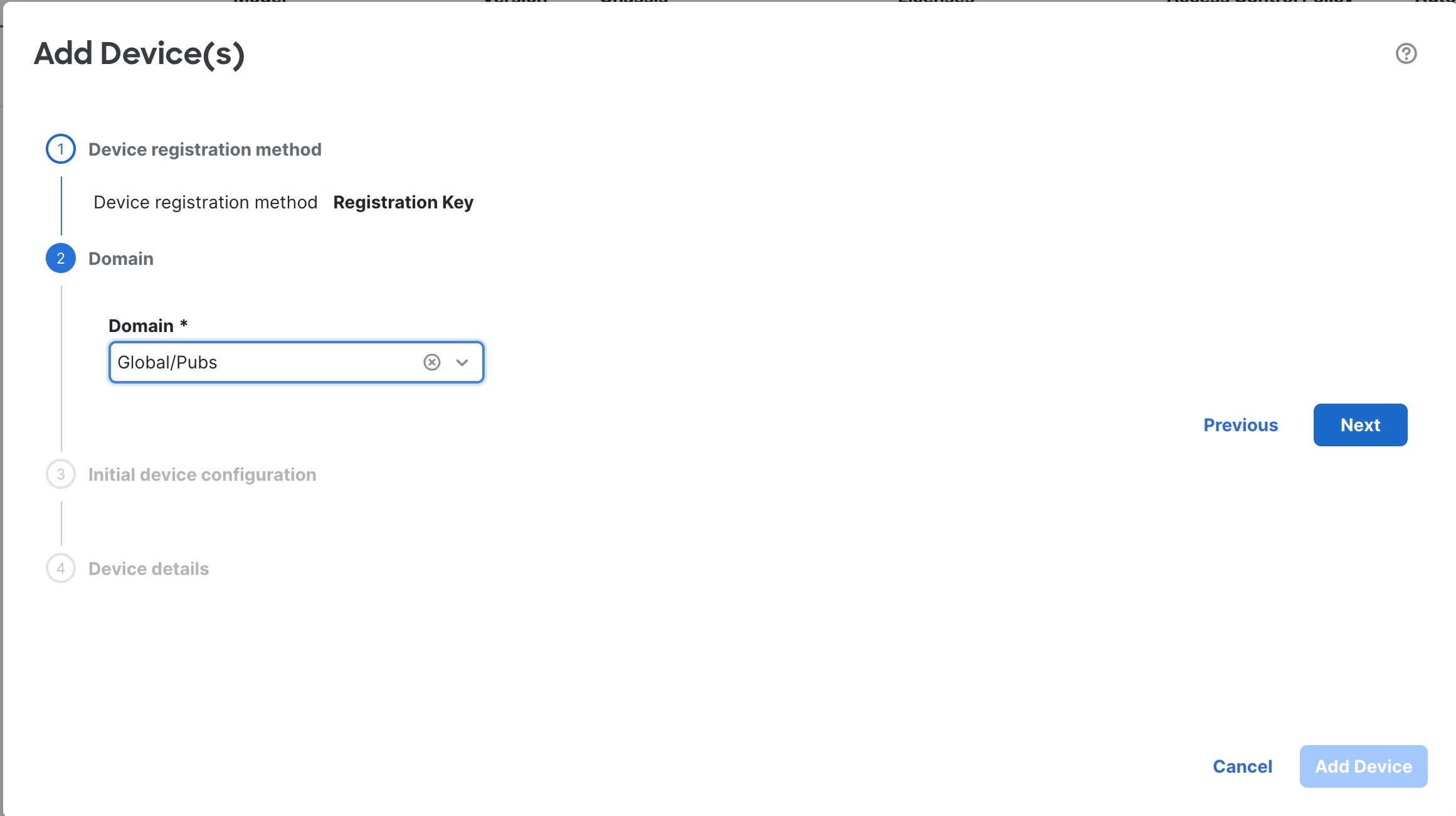
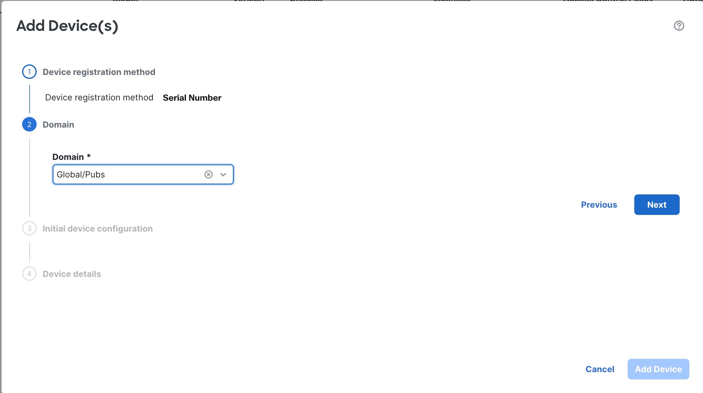
In a multi-domain environment, choose the Domain from the drop-down list and click Next.

Figure 14. Domain
Domain

Step 5

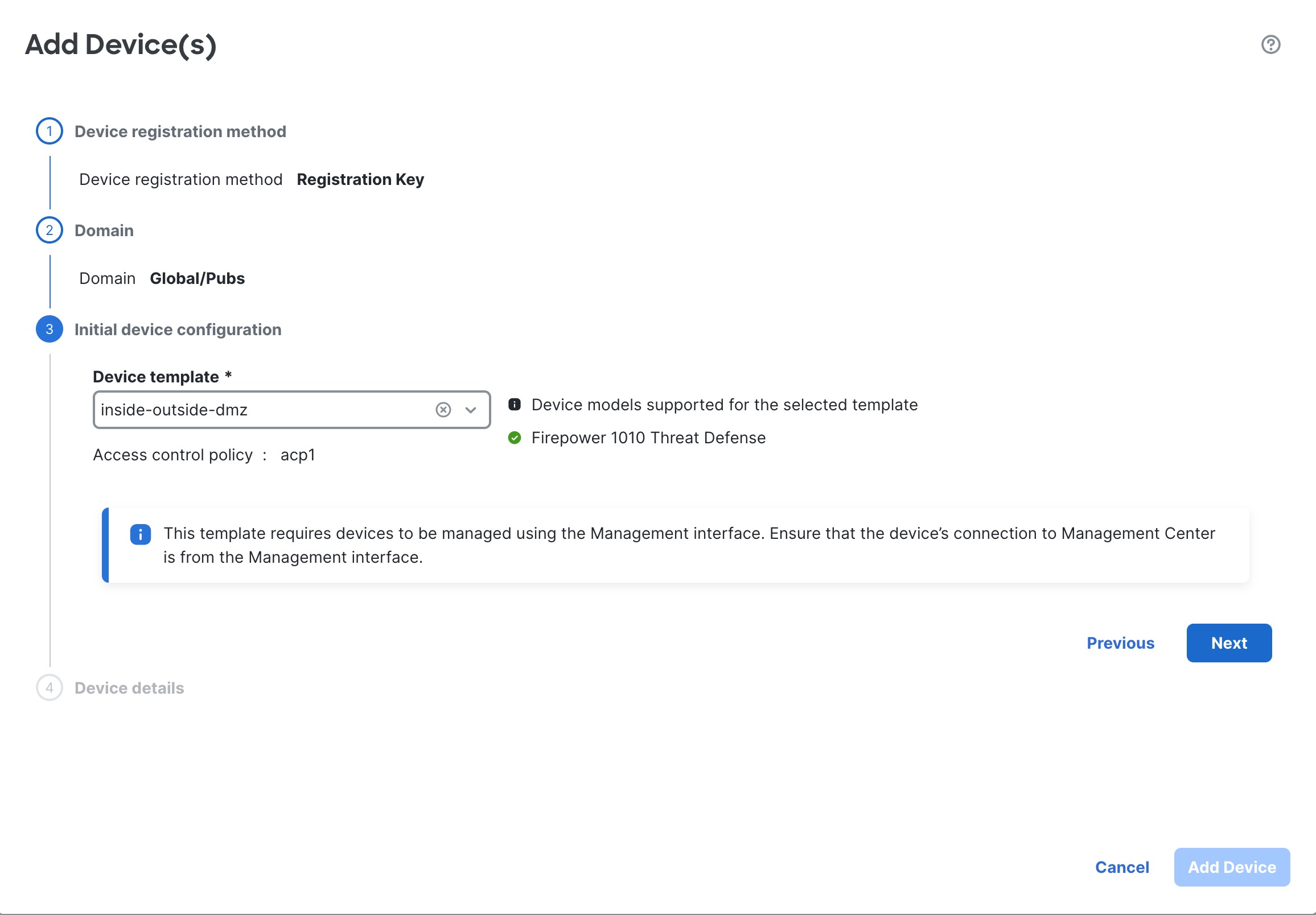
In Initial device configuration, choose a template from the Device template drop-down list.

Figure 15. Initial Device Configuration
Initial Device Configuration

Step 6

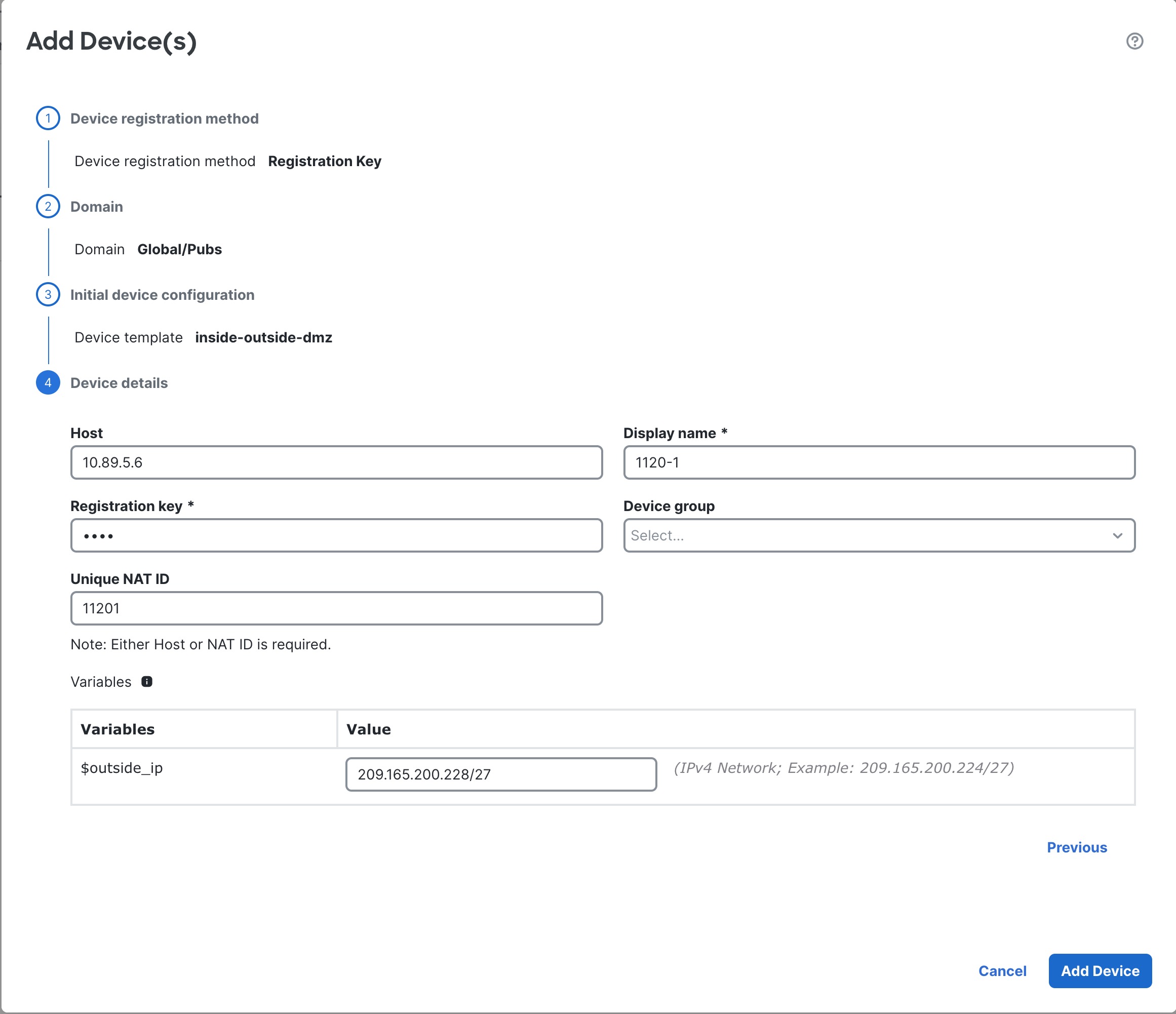
Specify the Device details.

Figure 16. Device Details
Device Details
  1. For the Host, enter the IP address or the hostname of the device you want to add. Leave this field blank if you don't know the device IP address (for example, it's behind NAT).

    If you leave this field blank, the initial configuration on the device needs to include a reachable management center IP address or hostname plus the NAT ID. For more information, see NAT Environments.

  2. For the Display name, enter a name for the device as you want it to display in the management center. You cannot change this name later.

  3. For the Registration Key, enter the same registration key in your initial configuration. The registration key is a one-time-use shared secret. The key can be up to 37-characters in length and include alphanumerical characters (A–Z, a–z, 0–9) and the hyphen (-). The registration key does not need to be unique per device.

  4. (Optional) Add the device to a Device group

  5. If you specified a NAT ID during initial configuration, enter the same NAT ID for the Unique NAT ID.

    The Unique NAT ID specifies a unique, one-time string of your choice that you will also specify on the device during initial configuration. It is required when one side does not specify a reachable IP address or hostname, for example if you left the Host field blank. Although technically optional, we recommend always specifying the NAT ID even when you know the IP addresses of both sides because it is required in certain situations. The ID can be up to 37-characters in length and include alphanumerical characters (A–Z, a–z, 0–9) and the hyphen (-). This ID cannot be used for any other devices registering to the management center.

  6. Check Transfer Packets so that for each intrusion event, the device transfers the packet to the management center for inspection.

    For each intrusion event, the device sends event information and the packet that triggered the event to the management center for inspection. If you disable it, only event information will be sent to the management center; the packet will not be sent.

  7. Enter values for the Variables and Network object overrides.

Step 7

Click Add Device to initiate device registration. The template configurations are applied after the device is successfully registered with the management center.


Serial Number Method (Zero-Touch Provisioning)

Zero-Touch Provisioning lets you register devices to the management center by serial number without having to perform any initial setup on the device.

Add a Device Using the Serial Number (Zero-Touch Provisioning)

Zero-Touch Provisioning lets you register devices to the management center by serial number without having to perform any initial setup on the device. The management center integrates with the Cisco Security Cloud and CDO for this functionality.

When you use zero-touch provisioning, the following interfaces are preconfigured. Note that other settings, such as the DHCP server on inside, access control policy, or security zones, are not configured.

  • Ethernet 1/1—"outside", IP address from DHCP, IPv6 autoconfiguration

  • Ethernet 1/2 (or for the Firepower 1010 and Secure Firewall 1210/1220, the VLAN1 interface)— "inside", 192.168.95.1/24

  • Default route—Obtained through DHCP on the outside interface

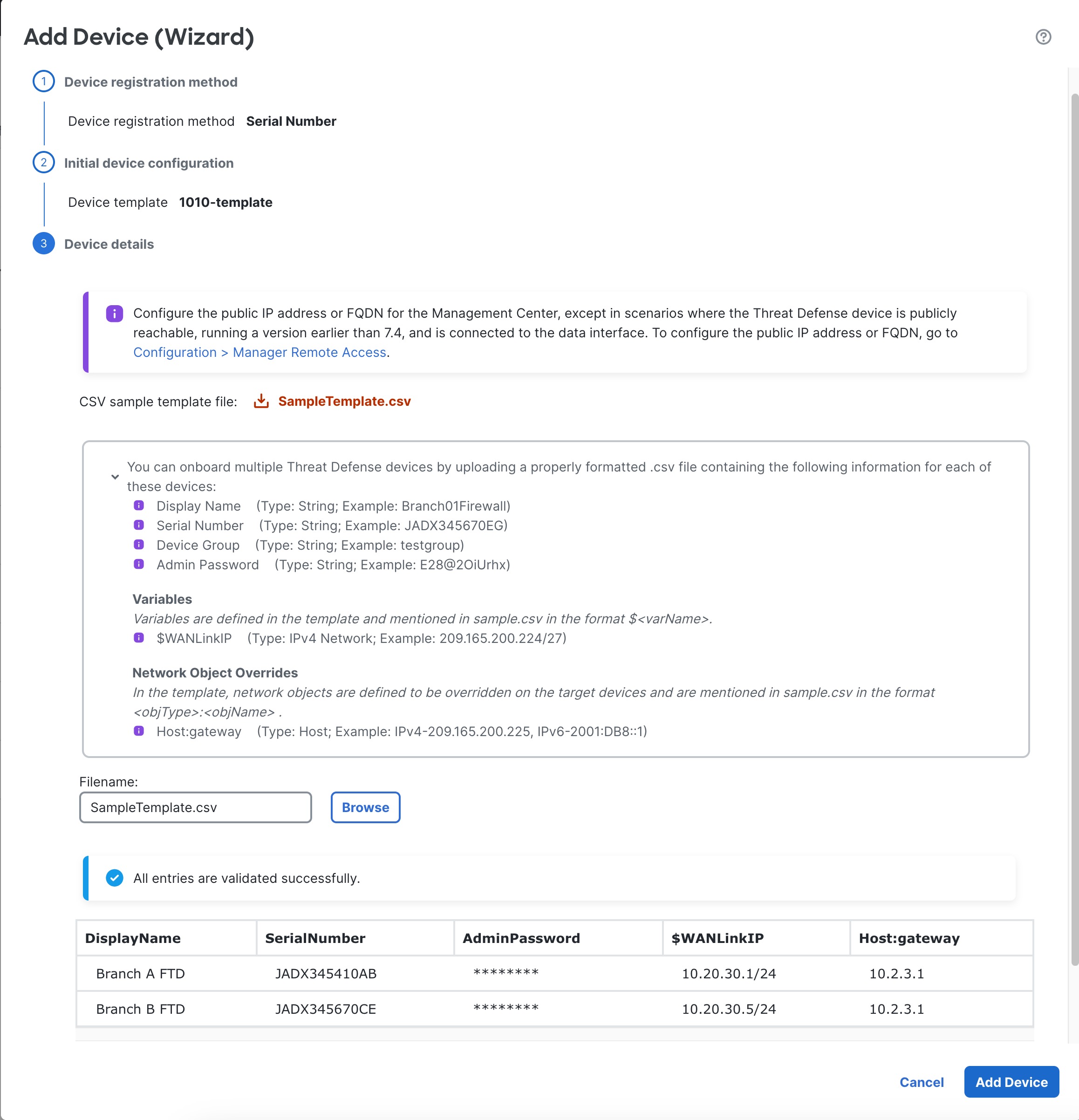
Use this procedure to add a single device to the management center using a basic configuration. To add one or more devices using a template, see Add Devices Using Serial Numbers (Zero-Touch Provisioning)—Device Template.

Zero-Touch Provisioning is not supported with clustering or multi-instance mode.

High availability is only supported when you use the Management interface because zero-touch provisioning uses DHCP, which is not supported for data interfaces and high availability.

Zero-Touch Provisioning is only supported on the following models using 7.2 and 7.4 or later; prior to 7.2.4, the management center must be publicly reachable.

  • Firepower 1010

  • Firepower 1100

  • Secure Firewall 1200

  • Firepower 2100 (on supported versions)

  • Secure Firewall 3100

Before you begin
  • Make sure the device is unconfigured or a fresh install. Zero-Touch Provisioning is meant for new devices only. Pre-configuration can disable zero-touch provisioning, depending on how you configure the device.

  • Cable the outside interface or Management interface so it can reach the internet. If you use the outside interface for zero-touch provisioning, do not also cable the Management interface; if the Management interface gets an IP address from DHCP, the routing will be incorrect for the outside interface.

  • If the device does not have a public IP address or FQDN, or you use the Management interface, set a public IP address/FQDN for the management center (for example, if it is behind NAT), so the device can initiate the management connection. See System > Configuration > Manager Remote Access.

  • The management center must be registered to the Smart Software Manager. A valid evaluation license is sufficient, but if it expires, you will not be able to add new devices until you successfully register.

  • If you registered a device using IPv4 and want to convert it to IPv6, you must unregister and reregister the device.

Procedure

Step 1

The first time you add a device using a serial number, integrate the management center with Cisco Security Cloud.

Note


For a management center high-availability pair, you also need to integrate the secondary management center with Cisco Security Cloud.

  1. Choose Integration > Cisco Security Cloud.

  2. Click Enable Cisco Security Cloud to open a separate browser tab to log you into your Cisco Security Cloud account and confirm the displayed code.

    Make sure this page is not blocked by a pop-up blocker. If you do not already have a Cisco Security Cloud and CDO account, you can add one during this procedure.

    For detailed information about this integration, see the "System Configuration" chapter in the Cisco Secure Firewall Management Center Administration Guide.

    CDO onboards the on-prem management center after you integrate the management center with Cisco Security Cloud. CDO needs the management center in its inventory for zero-touch provisioning to operate. However, you do not need to use CDO directly. If you do use CDO, its management center support is limited to device onboarding, viewing its managed devices, viewing objects associated with the management center, and cross-launching the management center.

  3. Make sure Enable Zero-Touch Provisioning is checked.

  4. Click Save.

Step 2

Choose Devices > Device Management.

Step 3

From the Add drop-down menu, choose Device (Wizard).

Step 4

Click Use Serial Number, and then click Next.

Figure 17. Device Registration Method
Device Registration Method

Step 5

In a multi-domain environment, choose the Domain from the drop-down list and click Next.

Figure 18. Domain
Domain

Step 6

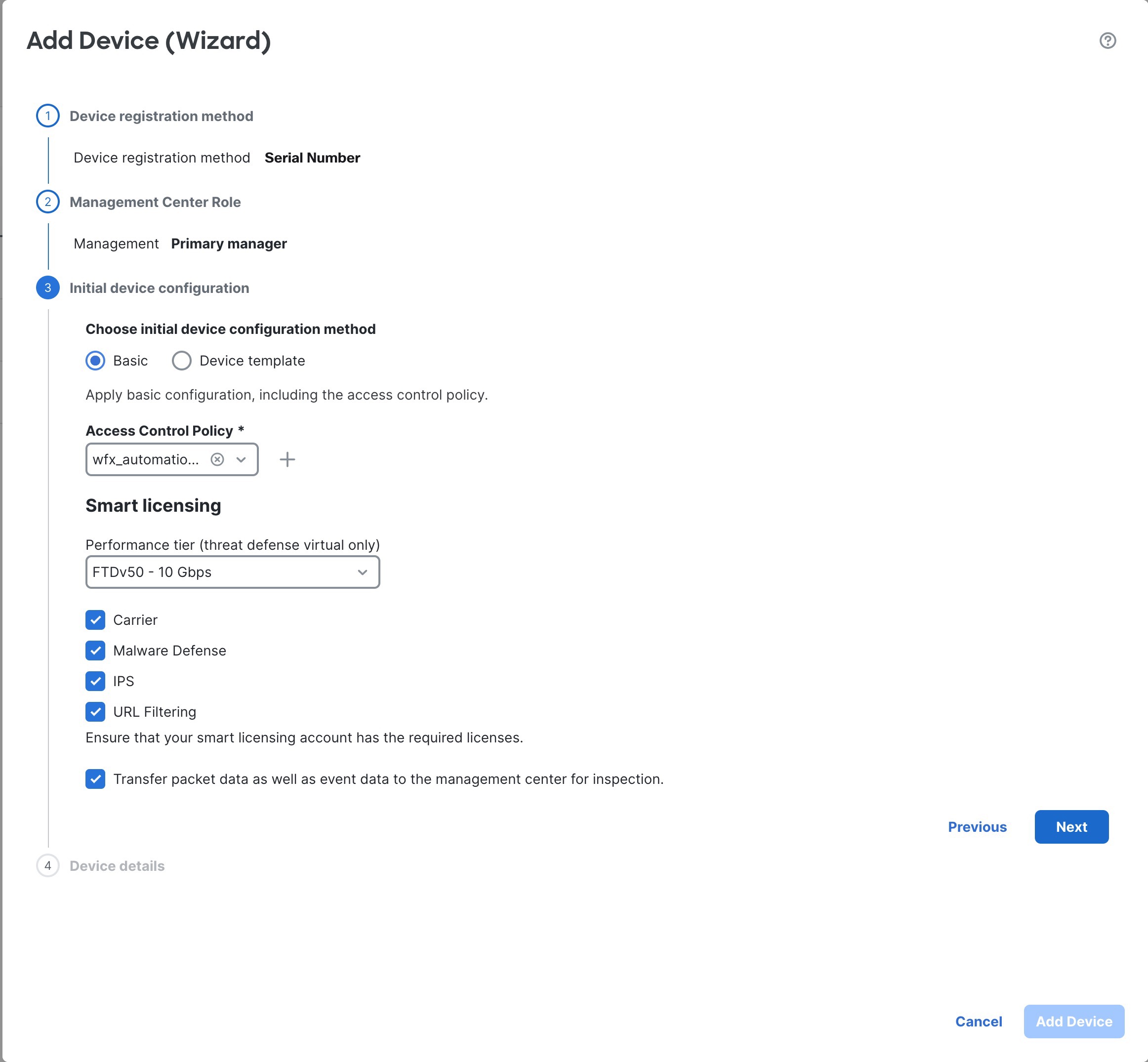
For the Initial device configuration, click the Basic radio button.

Figure 19. Initial Device Configuration Method
Initial Device Configuration Method
  1. Choose an initial Access Control Policy to deploy to the device upon registration, or create a new policy.

    If the device is incompatible with the policy you choose, deploying will fail. This incompatibility could occur for multiple reasons, including licensing mismatches, model restrictions, passive vs inline issues, and other misconfigurations. After you resolve the issue that caused the failure, manually deploy configurations to the device.

  2. Choose Smart licensing licenses to apply to the device.

    You can also apply licenses after you add the device, from the System > Licenses > Smart Licenses page.

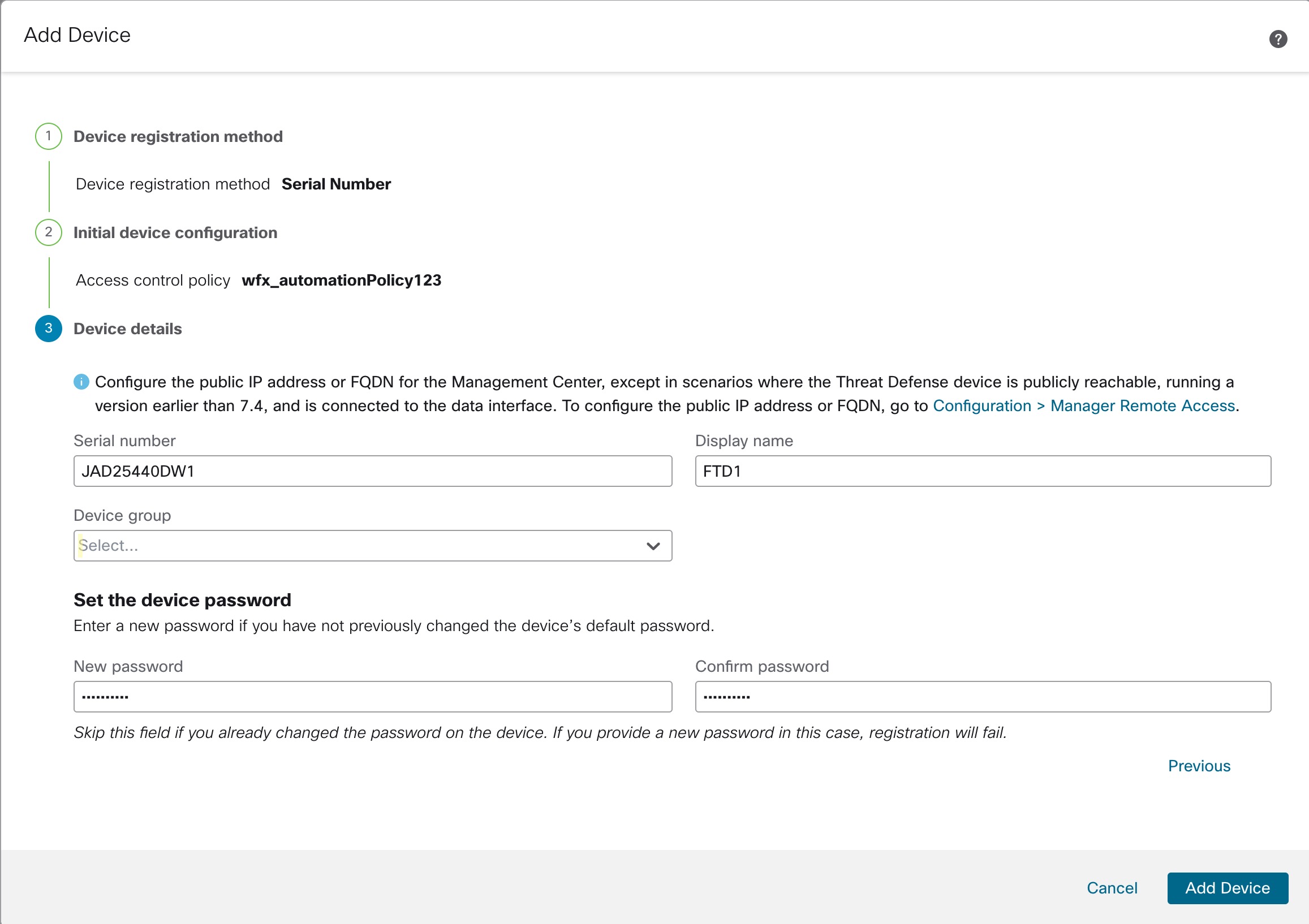
  3. Click Next.

Step 7

Configure the Device details.

Figure 20. Device details
Connection Settings
  1. Enter the Serial number.

  2. Enter the Display name as you want it to display in the management center

  3. (Optional) Choose the Device Group.

  4. Set the device password.

    If this device is unconfigured or a fresh install, then you need to set a new password. If you already logged in and changed the password, then leave this field blank. Otherwise, registration will fail.

Step 8

Click Add Device.

It may take up to two minutes for the management center to verify the device’s heartbeat and establish communication. If the registration succeeds, the device is added to the list.

When using zero-touch provisioning on the outside interface, CDO acts as a DDNS provider and does the following:

  • Enables DDNS on outside using the FMC Only method. This method is only supported for zero-touch provisioning devices.

  • Maps the outside IP address with the following hostname: serial-number.local.

  • Provides the IP address/hostname mapping to the management center so it can resolve the hostname to the correct IP address.

  • Informs the management center if the IP address ever changes, for example, if the DHCP lease renews.

If you use zero-touch provisioning on the Management interface, DDNS is not supported. The management center must be publicly reachable so the device can initiate the management connection.

You can continue to use CDO as the DDNS provider, or you can later change the DDNS configuration in the management center to a different method. See Configure Dynamic DNS for more information.

If the device fails to register, see Resolve Serial Number (Zero-Touch Provisioning) Registration Issues.


Add Devices Using Serial Numbers (Zero-Touch Provisioning)—Device Template

Zero-Touch Provisioning lets you register devices to the management center by serial number without having to perform any initial setup on the device. The management center integrates with the Cisco Security Cloud and CDO for this functionality.

You can use a template to add a device, register the device with the management center and bring up the device with template configurations.

Use this procedure to add devices to the management center using serial numbers and a device template. To add a device without using a template, see Add a Device Using the Serial Number (Zero-Touch Provisioning).

Zero-Touch Provisioning is not supported with clustering or multi-instance mode.

High availability is only supported when you use the Management interface because zero-touch provisioning uses DHCP, which is not supported for data interfaces and high availability.

Zero-Touch Provisioning is supported on the following models using 7.4 or later:

  • Firepower 1010

  • Firepower 1100

  • Secure Firewall 1200

  • Firepower 2100 (on supported versions)

  • Secure Firewall 3100

Before you begin
  • Make sure the device is unconfigured or a fresh install. Zero-Touch Provisioning is meant for new devices only. Pre-configuration can disable zero-touch provisioning, depending on how you configure the device.

  • Cable the outside interface or Management interface so it can reach the internet. If you use the outside interface for zero-touch provisioning, do not also cable the Management interface; if the Management interface gets an IP address from DHCP, the routing will be incorrect for the outside interface.

  • If the device does not have a public IP address or FQDN, or you use the Management interface, set a public IP address/FQDN for the management center (for example, if it is behind NAT), so the device can initiate the management connection. See System > Configuration > Manager Remote Access.

  • The management center must be registered to the Smart Software Manager. A valid evaluation license is sufficient, but if it expires, you will not be able to add new devices until you successfully register.

  • If you registered a device using IPv4 and want to convert it to IPv6, you must unregister and reregister the device.

  • Create a device template according to Device Management Using Device Templates. You must specify any required variables and network-object overrides for each device and ensure that model mapping is done for the target device model.

    We recommend that you create a checklist to ensure that all configurations in the template have been entered correctly before applying the template on the device.

    A sample checklist is given below.

    • Check version, model, operation modes.

    • Check list of variables and overrides.

    • Check sanity of variable and override values.

    • Check if the required Model Mappings exist.

    • Check if parallel device template operations are in progress.


    Note


    If you are adding a device that will be managed by a data interface, ensure that you configure the template to be compatible with the connectivity parameters of the device. For more information, see Configure a Template for Threat Defense Devices Managed Through the Data Interface.


Procedure

Step 1

The first time you add a device using a serial number, integrate the management center with Cisco Security Cloud.

Note


For a management center high-availability pair, you also need to integrate the secondary management center with Cisco Security Cloud.

  1. Choose Integration > Cisco Security Cloud.

  2. Click Enable Cisco Security Cloud to open a separate browser tab to log you into your Cisco Security Cloud account and confirm the displayed code.

    Make sure this page is not blocked by a pop-up blocker. If you do not already have a Cisco Security Cloud and CDO account, you can add one during this procedure.

    For detailed information about this integration, see the "System Configuration" chapter in the Cisco Secure Firewall Management Center Administration Guide.

    CDO onboards the on-prem management center after you integrate the management center with Cisco Security Cloud. CDO needs the management center in its inventory for zero-touch provisioning to operate. However, you do not need to use CDO directly. If you do use CDO, its management center support is limited to device onboarding, viewing its managed devices, viewing objects associated with the management center, and cross-launching the management center.

  3. Make sure Enable Zero-Touch Provisioning is checked.

  4. Click Save.

Step 2

Choose Devices > Device Management.

Step 3

From the Add drop-down menu, choose Device (Wizard).

Step 4

Click Use Serial Number, and then click Next.

Figure 21. Device Registration Method
Device Registration Method

Step 5

In a multi-domain environment, choose the Domain from the drop-down list and click Next.

Figure 22. Domain
Domain

Step 6

For the Initial device configuration, click the Device template radio button.

Figure 23. Initial Device Configuration
Initial Device Configuration

Step 7

Choose the Device template from the drop-down list, and click Next.

Step 8

In Device details, upload a CSV file with the device details required by the template.

Figure 24. Device Details
Device Details
  1. Download SampleTemplate.csv. This file includes all required headers for values that you need to define per device. For more information on the CSV template file fields, see CSV Template File.

  2. Drag & drop your CSV template file or Browse to select the CSV template file that you want to upload. A validation check is done on the file after you upload it.

    After the CSV template file has been uploaded successfully, the content of the CSV template file is displayed in a table format.

Step 9

Click Add Device to register the devices.

When using zero-touch provisioning on the outside interface, CDO acts as a DDNS provider and does the following:

  • Enables DDNS on outside using the "fmcOnly" method. This method is only supported for zero-touch provisioning devices.

  • Maps the outside IP address with the following hostname: serial-number.local.

  • Provides the IP address/hostname mapping to the management center so it can resolve the hostname to the correct IP address.

  • Informs the management center if the IP address ever changes, for example, if the DHCP lease renews.

If you use zero-touch provisioning on the Management interface, DDNS is not supported. The management center must be publicly reachable so the device can initiate the management connection.

You can continue to use CDO as the DDNS provider, or you can later change the DDNS configuration in the management center to a different method. See Configure Dynamic DNS for more information.

If the device fails to register, see Resolve Serial Number (Zero-Touch Provisioning) Registration Issues.


CSV Template File for Serial Number Registration with a Device Template

The CSV template file must be less than 2 MB in size. The filename must satisfy the following criteria:

  • Can have a maximum of 64 characters.

  • Only alphanumeric characters and special characters such as dash (-), period (.), and underscore (_) are allowed.

  • Must not contain any spaces.

See the following sample CSV template file containing configuration for two devices.


DisplayName,SerialNumber,AdminPassword,$WANLinkIP,Host:gateway
Branch A FTD,JADX345410AB,C15c05n0rt#,10.20.30.1/24,10.2.3.1
Branch B FTD,JADX345670CE,Admin123!,10.20.30.5/24,10.2.3.1

A properly formatted CSV file has the following fields.

Mandatory Fields
  • DisplayName—Name of the device. Type: string. Example: test1

  • SerialNumber—Serial number of the device. Type: string, Example: JADX345670EG

  • AdminPassword—Password for admin access, Type: string, Example: E28@2OiUrhx

Optional Fields
  • DeviceGroup—Name of the device group, Type: string, Example: testgroup

Variables

Use the following format: $varName.

Sample variable: $LAN-Devices-IPv4Address—IPv4 address of the LAN device. Type: string. Example: 10.2.3.4/24.

Network Object Overrides

Use the following format: objType:objName.

Sample network object override: Network:LAN-Devices-Network—IP address of the network of LAN devices. Type: string. Example: 10.2.3.0/24

FQDNs

For serial number registration, DDNS is automatically enabled. If you want to set different values from the default for the FMC Only type DDNS, then you can configure the settings in the template. In this case, when you provide the CSV value for the hostaname, be sure to specify it as serialnumber.local.

Add a Chassis

You can add a Firepower 4100/9300 chassis to the management center. The management center and the chassis share a separate management connection using the chassis MGMT interface. The management center offers chassis-level health alerts. For configuration, you still need to use the Secure Firewall chassis manager or FXOS CLI.


Note


For the Secure Firewall 3100/4200, the chassis is added to the management center as part of the conversion to multi-instance mode. See Convert a Device to Multi-Instance Mode. However, if you used the CLI to convert to multi-instance mode (Enable Multi-Instance Mode at the CLI), skip to Step 3 of this procedure to add the chassis to the management center.


Procedure

Step 1

Connect to the chassis FXOS CLI, either using the console port or SSH.

Step 2

Configure the management center.

create device-manager manager_name [hostname {hostname | ipv4_address | ipv6_address}] [nat-id nat_id]

You are prompted for the registration key.

You can enter this command from any scope. This command is accepted immediately without using commit-buffer .

  • hostname {hostname | ipv4_address | ipv6_address} —Specifies either the FQDN or IP address of the management center. At least one of the devices, either the management center or the chassis, must have a reachable IP address to establish the two-way, TLS-1.3-encrypted communication channel between the two devices. If you do not specify a hostname , then the chassis must have a reachable IP address or hostname and you must specify the nat-id.

  • nat-id nat_id —Specifies a unique, one-time string of your choice that you will also specify on the management center when you register the chassis when one side does not specify a reachable IP address or hostname. It is required if you do not specify a hostname , however we recommend that you always set the NAT ID even when you specify a hostname or IP address. The NAT ID must not exceed 37 characters. Valid characters include alphanumerical characters (A–Z, a–z, 0–9) and the hyphen (-). This ID cannot be used for any other devices registering to the management center.

  • Registration Key: reg_key —You will be prompted for a one-time registration key of your choice that you will also specify on the management center when you register the chassis. The registration key must not exceed 37 characters. Valid characters include alphanumerical characters (A–Z, a–z, 0–9) and the hyphen (-).

Example:

firepower# create device-manager boulder_fmc hostname 10.89.5.35 nat-id 93002
(Valid registration key characters: [a-z],[A-Z],[0-9],[-]. Length: [2-36])
Registration Key: Impala67

Step 3

In the management center, add the chassis using the chassis management IP address or hostname.

  1. Choose Device > Device Management, and then Add > Chassis.

    Figure 25. Add Chassis
    Add Chassis
    Figure 26. Add Chassis
    Add Chassis
  2. In the Hostname/IP Address field, enter the IP address or the hostname of the chassis you want to add.

    If you don't know the hostname or IP address, you can leave this field blank specify the Unique NAT ID.

  3. In the Chassis Name field, enter a name for the chassis as you want it to display in the management center.

  4. In the Registration Key field, enter the same registration key that you used when you configured the chassis to be managed by the management center.

    The registration key is a one-time-use shared secret. The key can include alphanumeric characters and hyphens (-).

  5. In a multidomain deployment, regardless of your current domain, assign the chassis to a leaf Domain.

    If your current domain is a leaf domain, the chassis is automatically added to the current domain. If your current domain is not a leaf domain, post-registration, you must switch to the leaf domain to configure the chassis. A chassis can only belong to one domain.

  6. (Optional) Add the chassis to a Device Group.

  7. If you used a NAT ID during chassis setup, expand enter the same NAT ID in the Unique NAT ID field.

    The NAT ID can include alphanumeric characters and hyphens (-).

  8. Click Submit.

    The chassis is added to the Device > Device Management page.


Register With a New Management Center

This procedure shows how to register with a new management center. You should perform these steps even if the new management center uses the old management center's IP address.

Procedure

Step 1

On the old management center, if present, unregister the managed device. See Unregister a Device from the Management Center.

You cannot change the management center IP address if you have an active connection with the management center.

Step 2

Connect to the device CLI, for example using SSH.

Step 3

Configure the new management center.

configure manager add {hostname | IPv4_address | IPv6_address | DONTRESOLVE } regkey [nat_id] [display_name]

  • {hostname | IPv4_address | IPv6_address}—Sets the management center hostname, IPv4 address, or IPv6 address.

  • DONTRESOLVE —If the management center is not directly addressable, use DONTRESOLVE instead of a hostname or IP address. If you use DONTRESOLVE , then a nat_id is required. When you add this device to the management center, make sure that you specify both the device IP address and the nat_id ; one side of the connection needs to specify an IP address, and both sides need to specify the same, unique NAT ID.

  • regkey —Make up a registration key to be shared between the management center and the device during registration. You can choose any text string for this key between 1 and 37 characters; you will enter the same key on the management center when you add the threat defense.

  • nat_id —Make up an alphanumeric string from 1 to 37 characters used only during the registration process between the management center and the device when one side does not specify an IP address. This NAT ID is a one-time password used only during registration. Make sure the NAT ID is unique, and not used by any other devices awaiting registration. Specify the same NAT ID on the management center when you add the threat defense.

  • display_name —Provide a display name for showing this manager with the show managers command. This option is useful if you are identifying CDO as the primary manager and an on-prem management center for analytics only. If you don't specify this argument, the firewall auto-generates a display name using one of the following methods:

    • hostname | IP_address (if you don't use the DONTRESOLVE keyword)

    • manager-timestamp

Example:

> configure manager add DONTRESOLVE abc123 efg456
Manager successfully configured.
Please make note of reg_key as this will be required while adding Device in FMC.

>

Step 4

Add the device to the management center.


Resolve Serial Number (Zero-Touch Provisioning) Registration Issues

If the device fails to register using the serial number, the device may not have successfully connected to the cloud. To confirm the cloud connection, check that the Managed Status LED is flashing green. If it is not flashing green, this failure might occur because:

  • You performed initial configuration at the CLI or the device manager and disabled low-touch provisioning

  • The serial number was already claimed by another manager

For other requirements for serial number registration, see Add a Device Using the Serial Number (Zero-Touch Provisioning).

To work around a registration failure, do one of the following tasks.

Reset the Device

Supported for the following models:

  • Firepower 1010

  • Firepower 1100

  • Secure Firewall 1200

  • Secure Firewall 3100

If you do not have access to the CLI and want to make sure your device is unconfigured and ready for zero-touch provisioning, reset the device to its default state by press the small, recessed Reset button for longer than five seconds. See your hardware installation guide for more information.

Use Manual Registration and a Registration Key

If low-touch provisioning fails, the easiest way to complete registration is to use the registration key method.

  1. See Complete the Threat Defense Initial Configuration for Manual Registration or Complete the Threat Defense Initial Configuration Using the Device Manager.

  2. If you are not presented with the initial setup tasks, it's possible your device was successfully registered to another management center. You must first delete the management connection and then re-register with the correct manager.

    1. First, check if registration has completed:

      
      > show managers
      Type                      : Manager
      Host                      : 10.10.1.4
      Display name              : 10.10.1.4
      Identifier                : f7ffad78-bf16-11ec-a737-baa2f76ef602
      Registration              : Completed
      Management type           : Configuration
       
    2. If Registration shows Completed, you need to delete the manager:

      configure manager delete

    3. You can then register the device at the CLI using configure manager add .

Restart Low-Touch Provisioning at the CLI

If the device was previously registered using low-touch provisioning, reregistration will fail, and you will see a Serial Number Already Claimed error in CDO.

You can unregister the serial number, clear the configuration and any existing management connection, and start the process over.

  1. Connect to the FXOS CLI using SSH or the console port.

    If you used SSH, you connect to the threat defense CLI. In this case, enter connect fxos . If you used the console port, you connect directly to FXOS.

    
    > connect fxos
    firepower# 
    
    
  2. Enter local management.

    connect local-mgmt

    
    firepower# connect local-mgmt
    firepower(local-mgmt)# 
  3. Deregister the device from the Cisco cloud.

    cloud deregister

    
    firepower(local-mgmt)# cloud deregister
    Release Image Detected RESULT=success MESSAGE=SUCCESS 10, X-Flow-Id: 2b3c9e8b-76c3-4764-91e4-cfd9828e73f9
    
    
  4. Erase the configuration to restore cloud connectivity.

    erase configuration

    
    firepower(local-mgmt)# erase configuration 
    All configurations will be erased and system will reboot. Are you sure? (yes/no):yes
    Removing all the configuration. Please wait....
    Configurations are cleaned up. Rebooting....
  5. Add a Device Using the Serial Number (Zero-Touch Provisioning)

Restart Low-Touch Provisioning Using the Device Manager

You can accidentally disable low-touch provisioning if you log into the device manager. In this case, you can restart low-touch provisioning within the device manager.


Note


If the serial number was already claimed, see Restart Low-Touch Provisioning at the CLI instead.


  1. In the device manager, click Device, then click the System Settings > Cloud Services.

  2. Check Auto-enroll with Cisco Defense Orchestrator or Secure Firewall Management Center.

  3. Click Register.

  4. Add a Device Using the Serial Number (Zero-Touch Provisioning)

Unregister a Device from the Management Center

If you no longer want to manage a device, you can unregister it from the management center.

To unregister a cluster, cluster node, or high availability pair, see the chapters for those deployments.

Unregistering a device:

  • Severs all communication between the management center and the device.

  • Removes the device from the Device Management page.

  • Returns the device to local time management if the device's platform settings policy is configured to receive time from the management center using NTP.

  • Leaves the configuration intact, so the device continues to process traffic.

    Policies, such as NAT and VPN, ACLs, and the interface configurations remain intact.

Registering the device again to the same or a different management center causes the configuration to be removed, so the device will stop processing traffic at that point.

Before you unregister the device, be sure to export the configuration or create a template so you can re-apply the device-level configuration (interfaces, routing, and so on) when you re-register it. If you do not have a saved configuration or template, you will have to re-configure device settings.

After you re-add the device and either import a saved configuration, use a template, or re-configure your settings, you need to deploy the configuration before it starts passing traffic again.

Before you begin

To re-apply the device-level configuration if you re-add it to the management center, do one of the following:

Procedure


Step 1

Choose Devices > Device Management.

Step 2

Next to the device you want to unregister, click More (more icon), and then click Unregister.

Figure 27. Unregister
Unregister

Step 3

Confirm that you want to unregister the device.

Step 4

You can now change your manager.


Shut Down or Restart the Device

It's important that you shut down your system properly. Simply unplugging the power or pressing the power switch can cause serious file system damage. Remember that there are many processes running in the background all the time, and unplugging or shutting off the power does not allow the graceful shutdown of your firewall.

See the following task to shut down or restart your system properly.


Note


After restarting your device, you may see an error that the management connection could not be reestablished. In some cases, the connection is attempted before the Management interface on the device is ready. The connection will be retried automatically and should come up within 15 minutes.


Procedure


Step 1

Choose Devices > Device Management.

Step 2

Next to the device that you want to restart, click Edit (edit icon).

Step 3

Click Device.

Step 4

To restart the device:

  1. Click Restart Device (restart device icon).

  2. When prompted, confirm that you want to restart the device.

Step 5

To shut down the device:

  1. Click Shut Down Device (shut down device icon) in the System section.

  2. When prompted, confirm that you want to shut down the device.

  3. If you have a console connection to the firewall, monitor the system prompts as the firewall shuts down. You will see the following prompt:

    
    System is stopped.
    It is safe to power off now.
    Do you want to reboot instead? [y/N]
    

    If you do not have a console connection, wait approximately 3 minutes to ensure the system has shut down.

    For the ISA 3000, when shutdown is complete, the System LED will turn off. Wait at least 10 seconds before you remove the power.


Download the Managed Device List

You can download a report of all the managed devices.

Before you begin

To perform the following task, you must be an Admin user.

Procedure


Step 1

Choose Devices > Device Management.

Step 2

Click the Download Device List Report link.

Step 3

You can download the device list in CSV or PDF format. Choose Download CSV or Download PDF to download the report.


Migrate the Configuration to a New Model

The Secure Firewall Threat Defense model migration wizard enables you to migrate configurations from an old model to a new model. You can map source device interfaces to target device interfaces. Before the migration, the source and target devices are locked.

Supported Devices for Migration

Supported Source Devices
  • Cisco Firepower 1120

  • Cisco Firepower 1140

  • Cisco Firepower 1150

  • Cisco Firepower 2110

  • Cisco Firepower 2120

  • Cisco Firepower 2130

  • Cisco Firepower 2140


Note


The source devices must be version 7.0 or later.


Supported Target Devices
  • Cisco Secure Firewall 3105

  • Cisco Secure Firewall 3110

  • Cisco Secure Firewall 3120

  • Cisco Secure Firewall 3130

  • Cisco Secure Firewall 3140


Note


The Cisco Secure Firewall 3110, 3120, 3130, and 3140 devices must be version 7.1 or later. Cisco Secure Firewall 3105 must be version 7.3 or later.


License for Migration

You must register and enroll the device with the smart licensing account. The migration copies the source device licenses to the target device.

Prerequisites for Migration

  • You must register the source and the target devices to the management center.

  • Your Smart Licensing account​ must have the license entitlements for the target device.

  • We recommend that the target device is a freshly registered device without any configurations.

  • Source and target devices must be in the same:

    • Domain

    • Firewall mode: Routed or Transparent

    • Compliance mode

  • The target device must not be:

    • In a multi-instance mode

    • Part of a cluster

  • The user must have modify permissions on the device.

  • The configurations on the source device must be valid and have no errors.

  • The source device can have pending deployments. However, deployment, import, or export tasks must not run on either of the devices during the migration.

  • If the source device is part of an HA pair, the target device need not be part of an HA pair and vice versa. The migration does not form or break the HA pair.

What Configurations Does the Wizard Migrate?

The migration wizard copies the following configurations from the source device to the target device:

  • Licenses

  • Interface configurations

  • Inline sets configurations

  • Routing configurations

  • DHCP and DDNS configurations

  • Virtual router configurations

  • Policies

  • Associated objects and object overrides

  • Platform settings

  • Remote branch deployment configurations

The migration wizard copies the following policy configurations from the source device to the target device:

  • Health policies

  • NAT policies

  • QoS policies

  • Remote access VPN policies

  • FlexConfig policies

  • Access control policies

  • Prefilter policies

  • IPS policies

  • DNS policies

  • SSL policies

  • Malware and File policies

  • Identity policies

The migration wizard copies the following routing configurations from the source device to the target device:

  • ECMP

  • BFD

  • OSPFv2/v3

  • EIGRP

  • RIP

  • BGP

  • Policy Based Routing

  • Static Route

  • Multicast Routing

  • Virtual Router

The migration wizard copies the following interfaces from the source device to the target device:

  • Physical interfaces

  • Sub-interfaces

  • Etherchannel interfaces

  • Bridge group interfaces

  • VTI interfaces

  • VNI interfaces

  • Loopback interfaces

Limitations for Migration

  • The wizard does not migrate:

    • Site-to-site VPN policies

    • SNMP configurations

      After the migration, you can configure SNMP using the platform settings for the device.

  • You can perform only one migration at a time.

  • If the speed, auto-negotiation, and duplex settings of the source interface are valid for the mapped interface of the target device, the values are copied. If not, these parameters are set to the default values.

  • Remote access VPN trustpoint certificates are not enrolled. You must manually enroll these certificates before the deployment.

  • After migration, by default, the target device uses Snort 3 and not Snort 2, even if the source device uses Snort 2.

  • For HA devices:

    • Target Device: You cannot map the interfaces that are part of the failover configuration. These interfaces are disabled in the wizard.

    • Source and Target Devices: The wizard does not migrate HA configurations such as monitored interfaces, failover trigger criteria, and interface MAC addresses. You must manually configure these parameters after the migration if required.

Migrate the Secure Firewall Threat Defense

Before you begin

Review the prerequisites and limitations for the migration.

Procedure

Step 1

Choose Devices > Device Management.

Step 2

Click Migrate on the top-right of the page.

Step 3

Click Start on the welcome screen.

Step 4

From the Source Device drop-down list, choose a device.

If the device is part of an HA pair, only the container name of the HA pair appears.

Step 5

Click Next.

Step 6

From the Target Device drop-down list, choose a device.

If the device is part of an HA pair, only the container name of the HA pair appears.

Step 7

Click Next.

Step 8

In the Configure Interfaces step, map the physical interfaces of the source device with those of the target device.

Mapping of all interfaces is not mandatory. You must map all named interfaces and interfaces that are part of other interfaces. You cannot map interfaces that are part of an HA failover configuration. These interfaces are disabled in the wizard. The wizard creates the logical interfaces according to the interface mapping provided by the user.

  • Click Map Default to configure default interface mappings.

    For example, Ethernet1/1 in the source device will be mapped to Ethernet1/1 in the target device.

  • Click Clear All to clear all the mappings.

Step 9

Click Next.

Step 10

Click View Mappings to verify the interface mappings.

Step 11

Click Submit to start the migration.

Step 12

View the migration status in the Notifications > Tasks page.


What to do next

After a successful migration, you can deploy the device.

Deployment is not mandatory, you can validate the configurations and deploy as required. However, before the deployment ensure that you perform the actions mentioned in Best Practices for Migration.

Best Practices for Migration

After a successful migration, we recommend that you perform the following actions before the deployment:

  • Change the IP addresses of the interfaces if the source device is live, as they are copied to the target device from the source device.

  • Ensure that you update your NAT policies with the modified IP addresses.

  • Configure the interface speeds if they are set to default values after migration.

  • Re-enroll the device certificates, if any, on the target device.

  • If you have a HA setup, configure HA parameters such as monitored interfaces, failover trigger criteria, and interface MAC addresses.

  • Configure the diagnostic interface as it gets reset after migration.

  • (Optional) Configure SNMP using the platform settings for the device.

  • (Optional) Configure remote branch deployment configurations.

    If the source or target device had manager access through a data interface, after the migration, the manager access will be lost. Update the manager access configuration on the target device. For more information, see the Change the Manager Access Interface from Management to Data topic in the Cisco Secure Firewall Management Center Device Configuration Guide or the Online Help.

  • (Optional) Configure site-to-site VPN if required. These configurations are not migrated from the source device.

  • View the deployment preview before the deployment. Choose Deploy > Advanced Deploy and click the Preview (preview icon) icon for the device.

Switch Managers

You can change between managers if needed.

Switch from the Device Manager to the Management Center

When you switch from the device manager to the management center, all interface configuration is retained, in addition to the Management interface and the manager access settings. Note that other configuration settings, such as the access control policy or security zones, are not retained.

After you switch to the management center, you can no longer use the device manager to manage the threat defense device.

Before you begin

If the firewall is configured for high availability, you must first break the high availability configuration using the device manager (if possible) or the configure high-availability disable command. Ideally, break high availability from the active unit.

Procedure


Step 1

In the device manager, unregister the device from the Cisco Smart Software Manager.

Step 2

(Might be required) Configure the Management interface.
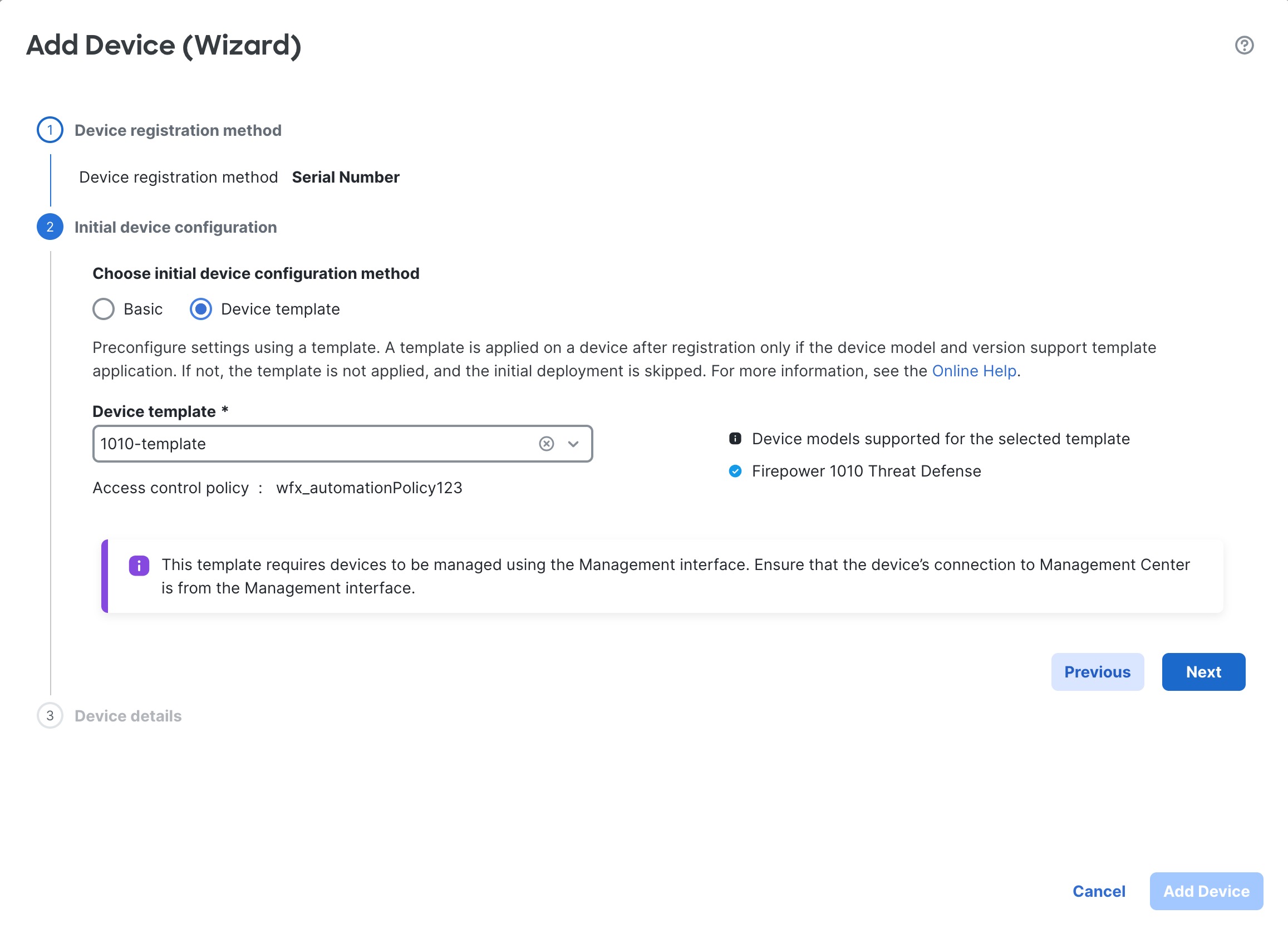
You may need to change the Management interface configuration, even if you intend to use a data interface for manager access. You will have to reconnect to the device manager if you were using the Management interface for the device manager connection.

  • Data interface for manager access—The Management interface must have the gateway set to data interfaces. By default, the Management interface receives an IP address and gateway from DHCP. If you do not receive a gateway from DHCP (for example, you did not connect this interface to a network), then the gateway will default to data interfaces, and you do not need to configure anything. If you did receive a gateway from DHCP, then you need to instead configure this interface with a static IP address and set the gateway to data interfaces.

  • Management interface for manager access—If you want to configure a static IP address, be sure to also set the default gateway to be a unique gateway instead of the data interfaces. If you use DHCP, then you do not need to configure anything assuming you successfully get the gateway from DHCP.

Step 3

Choose Device > System Settings > Central Management, and click Proceed to set up the management center management.

Step 4

Configure the Management Center/CDO Details.

Figure 28. Management Center/CDO Details
Management Center/CDO Details
  1. For Do you know the Management Center/CDO hostname or IP address, click Yes if you can reach the management center using an IP address or hostname, or No if the management center is behind NAT or does not have a public IP address or hostname.

    At least one of the devices, either the management center or the threat defense device, must have a reachable IP address to establish the two-way, TLS-1.3-encrypted communication channel between the two devices.

  2. If you chose Yes, then enter the Management Center/CDO Hostname/IP Address.

  3. Specify the Management Center/CDO Registration Key.

    This key is a one-time registration key of your choice that you will also specify on the management center when you register the threat defense device. The registration key must not exceed 37 characters. Valid characters include alphanumerical characters (A–Z, a–z, 0–9) and the hyphen (-). This ID can be used for multiple devices registering to the management center.

  4. Specify a NAT ID.

    This ID is a unique, one-time string of your choice that you will also specify on the management center. This field is required if you only specify the IP address on one of the devices; but we recommend that you specify the NAT ID even if you know the IP addresses of both devices. The NAT ID must not exceed 37 characters. Valid characters include alphanumerical characters (A–Z, a–z, 0–9) and the hyphen (-). This ID cannot be used for any other devices registering to the management center. The NAT ID is used in combination with the IP address to verify that the connection is coming from the correct device; only after authentication of the IP address/NAT ID will the registration key be checked.

Step 5

Configure the Connectivity Configuration.

  1. Specify the FTD Hostname.

    If you use a data interface for the Management Center/CDO Access Interface access, then this FQDN will be used for this interface.

  2. Specify the DNS Server Group.

    Choose an existing group, or create a new one. The default DNS group is called CiscoUmbrellaDNSServerGroup, which includes the OpenDNS servers.

    If you intend to choose a data interface for the Management Center/CDO Access Interface, then this setting sets the data interface DNS server. The Management DNS server that you set with the setup wizard is used for management traffic. The data DNS server is used for DDNS (if configured) or for security policies applied to this interface. You are likely to choose the same DNS server group that you used for Management, because both management and data traffic reach the DNS server through the outside interface.

    On the management center, the data interface DNS servers are configured in the Platform Settings policy that you assign to this threat defense device. When you add the threat defense device to the management center, the local setting is maintained, and the DNS servers are not added to a Platform Settings policy. However, if you later assign a Platform Settings policy to the threat defense device that includes a DNS configuration, then that configuration will overwrite the local setting. We suggest that you actively configure the DNS Platform Settings to match this setting to bring the management center and the threat defense device into sync.

    Also, local DNS servers are only retained by the management center if the DNS servers were discovered at initial registration.

    If you intend to choose the Management interface for the CDOFMC Access Interface, then this setting configures the Management DNS server.

  3. For the Management Center/CDO Access Interface, choose any configured interface.

    You can change the manager interface after you register the threat defense device to the management center, to either the Management interface or another data interface.

Step 6

(Optional) If you chose a data interface, and it was not the outside interface, then add a default route.

You will see a message telling you to check that you have a default route through the interface. If you chose outside, you already configured this route as part of the setup wizard. If you chose a different interface, then you need to manually configure a default route before you connect to the management center.

If you chose the Management interface, then you need to configure the gateway to be a unique gateway before you can proceed on this screen.

Step 7

(Optional) If you chose a data interface, click Add a Dynamic DNS (DDNS) method.

DDNS ensures the management center can reach the threat defense device at its Fully-Qualified Domain Name (FQDN) if the IP address changes. See Device > System Settings > DDNS Service to configure DDNS.

If you configure DDNS before you add the threat defense device to the management center, the threat defense device automatically adds certificates for all of the major CAs from the Cisco Trusted Root CA bundle so that the threat defense device can validate the DDNS server certificate for the HTTPS connection. Threat Defense supports any DDNS server that uses the DynDNS Remote API specification (https://help.dyn.com/remote-access-api/).

DDNS is not supported when using the Management interface for manager access.

Step 8

Click Connect. The Registration Status dialog box shows the current status of the switch to the management center. After the Saving Management Center/CDO Registration Settings step, go to the management center, and add the firewall.

If you want to cancel the switch to the management center, click Cancel Registration. Otherwise, do not close the device manager browser window until after the Saving Management Center/CDO Registration Settings step. If you do, the process will be paused, and will only resume when you reconnect to the device manager.

If you remain connected to the device manager after the Saving Management Center/CDO Registration Settings step, you will eventually see the Successful Connection with Management Center or CDO dialog box, after which you will be disconnected from the device manager.

Figure 29. Successful Connection
Successful Connection

Switch from Management Center to Device Manager

You can configure the threat defense device currently being managed by the on-premises or cloud-delivered management center to use the device manager instead.

You can switch from the management center to the device manager without reinstalling the software. Before switching from the management center to the device manager, verify that the device manager meets all of your configuration requirements. If you want to switch from the device manager to the management center, see Switch from the Device Manager to the Management Center.


Caution


Switching to the device manager erases the device configuration and returns the system to the default configuration. However, the Management IP address and hostname are preserved.


Procedure


Step 1

In the management center, unregister the firewall from the Devices > Device Management page.

Step 2

Connect to the threat defense CLI using SSH or the console port. For SSH, open a connection to the management IP address, and log into the threat defense CLI with the admin username (or any other user with admin privileges).

The console port defaults to the FXOS CLI. Connect to the threat defense CLI using the connect ftd command. The SSH session connects directly to the threat defense CLI.

If you cannot connect to the management IP address, do one of the following:

  • Ensure that the Management physical port is wired to a functioning network.

  • Ensure that the management IP address and gateway are configured for the management network. Use the configure network ipv4/ipv6 manual command.

Step 3

Verify you are currently in remote management mode.

show managers

Example:


> show managers
Type                      : Manager
Host                      : 10.89.5.35
Display name              : 10.89.5.35
Identifier                : f7ffad78-bf16-11ec-a737-baa2f76ef602
Registration              : Completed

Step 4

Delete the remote manager and go into no manager mode.

configure manager delete uuid

You cannot go directly from remote management to local management. If you have more than one manager defined, you need to specify the identifier (also known as the UUID; see the show managers command). Delete each manager entry separately.

Example:


> configure manager delete 
Deleting task list
Manager successfully deleted.

> 
> show managers 
No managers configured.

Step 5

Configure the local manager.

configure manager local

You can now use a web browser to open the local manager at https://management-IP-address .

Example:


> configure manager local 
Deleting task list

> show managers 
Managed locally.


Hot Swap an SSD on the Secure Firewall 3100/4200

If you have two SSDs, they form a RAID when you boot up. You can perform the following tasks at the threat defense CLI while the firewall is powered up:

  • Hot swap one of the SSDs—If an SSD is faulty, you can replace it. Note that if you only have one SSD, you cannot remove it while the firewall is powered on.

  • Remove one of the SSDs—If you have two SSDs, you can remove one.

  • Add a second SSD—If you have one SSD, you can add a second SSD and form a RAID.


Caution


Do not remove an SSD without first removing it from the RAID using this procedure. You can cause data loss.


Procedure


Step 1

Remove one of the SSDs.

  1. Remove the SSD from the RAID.

    configure raid remove-secure local-disk {1 | 2}

    The remove-secure keyword removes the SSD from the RAID, disables the self-encrypting disk feature, and performs a secure erase of the SSD. If you only want to remove the SSD from the RAID and want to keep the data intact, you can use the remove keyword.

    Example:

    
    > configure raid remove-secure local-disk 2
    
    
  2. Monitor the RAID status until the SSD no longer shows in the inventory.

    show raid

    After the SSD is removed from the RAID, the Operability and Drive State will show as degraded. The second drive will no longer be listed as a member disk.

    Example:

    
    > show raid
    Virtual Drive
    ID:                         1
    Size (MB):                  858306
    Operability:                operable
    Presence:                   equipped
    Lifecycle:                  available
    Drive State:                optimal
    Type:                       raid
    Level:                      raid1
    Max Disks:                  2
    Meta Version:               1.0
    Array State:                active
    Sync Action:                idle
    Sync Completed:             unknown
    Degraded:                   0
    Sync Speed:                 none
    
    RAID member Disk:
    Device Name:                nvme0n1
    Disk State:                 in-sync
    Disk Slot:                  1
    Read Errors:                0
    Recovery Start:             none
    Bad Blocks:
    Unacknowledged Bad Blocks:   
    
    Device Name:                nvme1n1
    Disk State:                 in-sync
    Disk Slot:                  2
    Read Errors:                0
    Recovery Start:             none
    Bad Blocks:
    Unacknowledged Bad Blocks:   
    
    > show raid
    Virtual Drive
    ID:                         1
    Size (MB):                  858306
    Operability:                degraded
    Presence:                   equipped
    Lifecycle:                  available
    Drive State:                degraded
    Type:                       raid
    Level:                      raid1
    Max Disks:                  2
    Meta Version:               1.0
    Array State:                active
    Sync Action:                idle
    Sync Completed:             unknown
    Degraded:                   1
    Sync Speed:                 none
    
    RAID member Disk:
    Device Name:                nvme0n1
    Disk State:                 in-sync
    Disk Slot:                  1
    Read Errors:                0
    Recovery Start:             none
    Bad Blocks:
    Unacknowledged Bad Blocks:   
    
    
  3. Physically remove the SSD from the chassis.

Step 2

Add an SSD.

  1. Physically add the SSD to the empty slot.

  2. Add the SSD to the RAID.

    configure raid add local-disk {1 | 2}

    It can take several hours to complete syncing the new SSD to the RAID, during which the firewall is completely operational. You can even reboot, and the sync will continue after it powers up. Use the show raid command to show the status.

    If you install an SSD that was previously used on another system, and is still locked, enter the following command:

    configure raid add local-disk {1 | 2} psid

    The psid is printed on the label attached to the back of the SSD. Alternatively, you can reboot the system, and the SSD will be reformatted and added to the RAID.


Disable the USB Port

By default, the type-A USB port is enabled. You might want to disable USB port access for security purposes. Disabling USB is supported on the following models:

  • Firepower 1000 Series

  • Secure Firewall 3100

  • Secure Firewall 4200

Guidelines

  • Enabling or disabling the USB port requires a reboot.

  • If the USB port is disabled and you downgrade to a version that does not support this feature, the port will remain disabled, and you cannot re-enable it without erasing the NVRAM (the FXOS local-mgmt erase secure all command).

  • If you perform a ROMMON factory-reset or FXOS local-mgmt erase secure , the USB port will be re-enabled.

  • For high availability or clustering, you must disable or re-enable the port individually on each unit.


Note


This feature does not affect the USB console port, if present.


Disable the USB Port on a Device

To disable the USB port on a device, you can do so at the threat defense CLI.

Procedure


Step 1

Disable the USB port.

system support usb configure disable

reboot

To re-enable the USB port, enter system support usb configure enable .

Example:


>system support usb configure disable
USB Port Admin State set to 'disabled’.
Please reboot the system to apply any control state changes.

>reboot
This command will reboot the system. Continue?
Please enter 'YES' or 'NO': YES

Step 2

View the port status.

system support usb show

The Admin State shows the USB port configuration. The Oper State shows the current operation. For example, if you disable the USB port but do not reload, the Admin State will show disabled while the Oper State would will enabled.

Example:


>system support usb show
USB Port Info
---------------
Admin State: disabled
Oper State: disabled

Disable the USB Port in Multi-Instance Mode

To disable the USB port in multi-instance mode, you can do so at the FXOS CLI.

Procedure


Step 1

Disable the USB port and reboot for the change to take effect.

  1. Disable the USB port.

    scope fabric-interconnect

    disable usb-port

    commit buffer

  2. Reboot the chassis.

    connect local-mgmt

    reboot

Example:


firepower-4245 /fabric-interconnect # disable usb-port
Note: USB enablement or disablement changes are effected only after FXOS reboot.
Confirm change? (yes/no) [yes]:
device /fabric-interconnect* # commit buffer
Note: USB enablement or disablement changes are effected only after FXOS reboot.
Confirm change? (yes/no) [yes]:yes
firepower-4245 /fabric-interconnect # connect local-mgmt
firepower-4245(local-mgmt)# reboot
Before rebooting, please take a configuration backup.
Do you still want to reboot? (yes/no):yes
Broadcast message from admin@firepower-4245 (Wed Feb 21 05:59:55 2024):
All shells being terminated due to system /sbin/reboot

Step 2

Enable the USB port and reboot for the change to take effect.

  1. Enable the USB port.

    scope fabric-interconnect

    enable usb-port

    commit buffer

  2. Reboot the chassis.

    connect local-mgmt

    reboot

Example:


firepower-4245 /fabric-interconnect # enable usb-port
Note: USB enablement or disablement changes are effected only after FXOS reboot.
Confirm change? (yes/no) [yes]:
device /fabric-interconnect* # commit buffer
Note: USB enablement or disablement changes are effected only after FXOS reboot.
Confirm change? (yes/no) [yes]:yes
firepower-4245 /fabric-interconnect # connect local-mgmt
firepower-4245(local-mgmt)# reboot
Before rebooting, please take a configuration backup.
Do you still want to reboot? (yes/no):yes
Broadcast message from admin@firepower-4245 (Wed Feb 21 05:59:55 2024):
All shells being terminated due to system /sbin/reboot

Step 3

View the USB port status.

scope fabric-interconnect

show usb-port

The Admin State shows the USB port configuration. The Oper State shows the current operation. For example, if you disable the USB port but do not reload, the Admin State will show Disabled while the Oper State would will Enabled.

Example:


firepower-4245# scope fabric-interconnect
firepower-4245 /fabric-interconnect # show usb-port
Usb Port:
Equipment         Admin State Oper State
---------------- -----------  ----------
A                 Disabled    Disabled


History for Device Management

Feature

Minimum Management Center

Minimum Threat Defense

Details

Serial-number registration (zero-touch provisioning) supported from an on-prem management center.

7.6.0

Mgmt. center must be publicly reachable: 7.2.0

Restriction removed: 7.2.4/7.4.0

You can now register a device using its serial number from an on-prem management center. With templates (requires threat defense 7.4.1+ on the device), you can register multiple devices at once. This feature was previously known as low-touch provisioning.

Requires Cisco Security Cloud. For upgraded management centers, your existing CDO integration continues to work until you enable Cisco Security Cloud.

New/modified screens: Devices > Device Management > Add > Device (Wizard)

Supported platforms: Firepower 1000/2100, Secure Firewall 1200/3100. Note that Firepower 2100 support is for threat defense 7.4.1–7.4.x only; those devices cannot run Version 7.6.0.

Delete menu item renamed to Unregister

7.6.0

Any

The Delete menu choice was renamed to Unregister to better indicate that the device, high-availability pair, or cluster is being unregistered from the management center and not deleted from the high availability pair or cluster or having its configuration erased. The device, high-availability pair, or cluster continues to pass traffic until it is re-registered.

New/modified screens: Devices > Device Management > More (more icon)

Add devices using templates

7.6.0

7.4

The Devices > Device Management > Add > Device (Wizard) screen lets you add devices using a template.

New/modified screens: Devices > Device Management > Add > Device (Wizard)

Disable the front panel USB-A port on the Firepower 1000 and Secure Firewall 3100/4200.

7.6.0

7.6.0

You can now disable the front panel USB-A port on the Firepower 1000 and Secure Firewall 3100/4200. By default, the port is enabled.

New/modified threat defense CLI commands: system support usb show , system support usb port disable , system support usb port enable

New/modified FXOS CLI commands for the Secure Firewall 3100/4200 in multi-instance mode: show usb-port , disable USB port , enable usb-port

See: Cisco Secure Firewall Threat Defense Command Reference and Cisco Firepower 4100/9300 FXOS Command Reference

Chassis-level health alerts for the Firepower 4100/9300.

7.4.1

7.4.1

You can now view chassis-level health alerts for Firepower 4100/9300 by registering the chassis to the management center as a read-only device. You must also enable the Firewall Threat Defense Platform Faults health module and apply the health policy. The alerts appear in the Message Center, the health monitor (in the left pane, under Devices, select the chassis), and in the health events view.

You can also add a chassis (and view health alerts for) the Secure Firewall 3100 in multi-instance mode. For those devices, you use the management center to manage the chassis. But for the Firepower 4100/9300 chassis, you still must use the chassis manager or the FXOS CLI.

New/modified screens: Devices > Device Management > Add > Chassis

Zero-Touch Provisioning to register the Firepower 1000/2100 and Secure Firewall 3100 to the management center using a serial number.

7.4.0

Mgmt. center is publicly reachable: 7.2.0

Mgmt. center is not publicly reachable: 7.2.4/7.4.0

Zero-Touch Provisioning (also called low-touch provisioning) lets you register Firepower 1000/2100 and Secure Firewall 3100 devices to the management center by serial number without having to perform any initial setup on the device. The management center integrates with SecureX and Cisco Defense Orchestrator for this functionality.

New/modified screens: Devices > Device Management > Add > Device > Serial Number

Other version restrictions: This feature is not supported on Version 7.3.x or 7.4.0 threat defense devices when the management center is not publicly reachable. Support returns in Version 7.4.1.

Merged management and diagnostic interfaces.

7.4.0

7.4.0

Upgrade impact. Merge interfaces after upgrade.

For new devices using 7.4 and later, you cannot use the legacy diagnostic interface. Only the merged management interface is available.

If you upgraded to 7.4 or later and:

  • You did not have any configuration for the diagnostic interface, then the interfaces will merge automatically.

  • You have configuration for the diagnostic interface, then you have the choice to merge the interfaces manually, or you can continue to use the separate diagnostic interface. Note that support for the diagnostic interface will be removed in a later release, so you should plan to merge the interfaces as soon as possible.

Merged mode also changes the behavior of AAA traffic to use the data routing table by default. The management-only routing table can now only be used if you specify the management-only interface (including Management) in the configuration.

For platform settings, this means:

  • You can no longer enable HTTP, ICMP, or SMTP for diagnostic.

  • For SNMP, you can allow hosts on management instead of diagnostic.

  • For Syslog servers, you can reach them on management instead of diagnostic.

  • If Platform Settings for syslog servers or SNMP hosts specify the diagnostic interface by name, then you must use separate Platform Settings policies for merged and non-merged devices.

  • DNS lookups no longer fall back to the management-only routing table if you do not specify interfaces.

New/modified screens: Devices > Device Management > Interfaces

New/modified commands: show management-interface convergence

Migrate from Firepower 1000/2100 to Secure Firewall 3100.

7.4.0

Any

You can now easily migrate configurations from the Firepower 1000/2100 to the Secure Firewall 3100.

New/modified screens: Devices > Device Management > Migrate

Platform restrictions: Migration not supported from the Firepower 1010 or 1010E.

Download a report of all registered devices.

7.4.0

Any

You can now download a report of all registered devices. On Devices > Device Management, click the new Download Device List Report link, at the top right of the page.

Manage threat defense high availability pairs using a data interface.

7.4.0

7.4.0

Threat defense high availability now supports using a regular data interface for communication with the management center. Previously, only standalone devices supported this feature.

See: Using the Threat Defense Data Interface for Management

ISA 3000 System LED support for shutting down.

7.0.5/7.3.0

7.0.5/7.3.0

When you shut down the ISA 3000, the System LED will turn off. You should wait at least 10 seconds before removing the power.

ISA 3000 support for shutting down.

7.0.2/7.2.0

7.0.2/7.2.0

You can now shut down the ISA 3000; previously, you could only reboot the device.

Multi-manager support.

7.2.0

7.2.0

We introduced the cloud-delivered management center. The cloud-delivered management center uses the Cisco Defense Orchestrator (CDO) platform and unites management across multiple Cisco security solutions. We take care of manager updates.

Hardware or virtual management centers running Version 7.2+ can "co-manage" cloud-managed devices, but for event logging and analytics purposes only. You cannot deploy policy to these devices from the hardware or virtual management center.

New/modified commands: configure manager add , configure manager delete , configure manager edit , show managers

New/modified screens:

  • When you add a cloud-managed device to a hardware or virtual management center, use the new CDO Managed Device check box to specify that it is analytics-only.

  • View which devices are analytics-only on Devices > Device Management.

For more information, see CDO documentation.

RAID support for SSDs on the Secure Firewall 3100.

7.1.0

7.1.0

The SSDs are self-encrypting drives (SEDs), and if you have 2 SSDs, they form a software RAID.

New/modified commands: configure raid, show raid, show ssd

Support for TLS 1.3 for the management connection.

7.1.0

7.1.0

The FMC-device management connection now uses TLS 1.3. Previously, TLS 1.2 was supported.

Use FDM to configure FTD for management by the FMC.

7.1.0

7.1.0

When you perform initial setup using FDM, all interface configuration completed in FDM is retained when you switch to FMC for management, in addition to the Management and manager access settings. Note that other default configuration settings, such as the access control policy or security zones, are not retained. When you use the FMC CLI, only the Management and manager access settings are retained (for example, the default inside interface configuration is not retained).

After you switch to FMC, you can no longer use FDM to manage FTD.

New/modified FDM screens: System Settings > Management Center

Filter devices by upgrade status.

6.7.0

6.7.0

The Device Management page now provides upgrade information about your managed devices, including whether a device is upgrading (and what its upgrade path is), and whether its last upgrade succeeded or failed.

New/modified screens: Devices > Device Management

One-click access to the Firepower Chassis Manager.

6.4.0

6.4.0

For Firepower 4100/9300 series devices, the Device Management page provides a link to the Firepower Chassis Manager web interface.

New/modified screens: Devices > Device Management

Filter devices by health and deployment status; view version information.

6.2.3

6.2.3

The Device Management page now provides version information for managed devices, as well as the ability to filter devices by health and deployment status.

New/modified screens: Devices > Device Management