Device Management Using Device Templates

You can add devices to the management center using device templates.

About Device Management using Device Templates

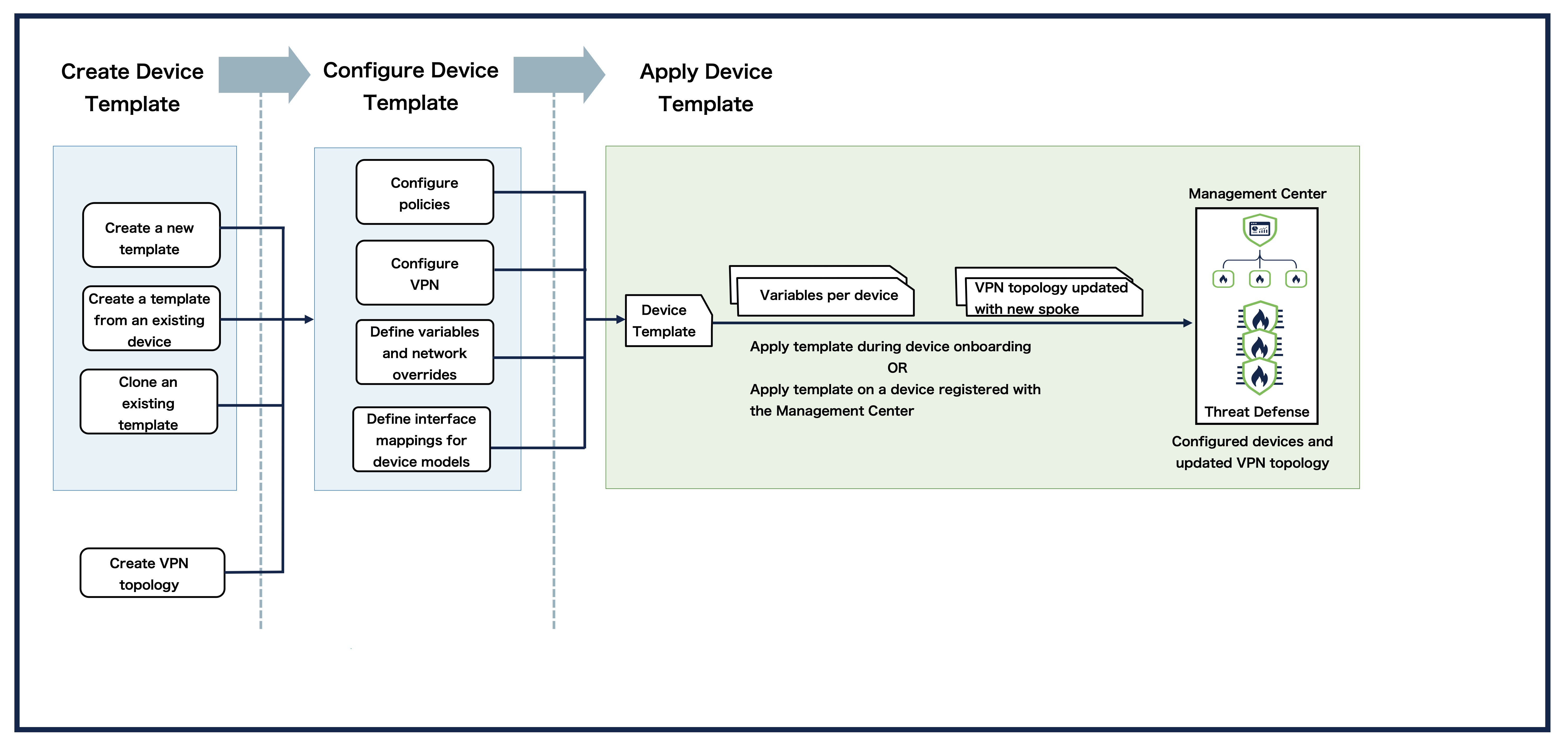
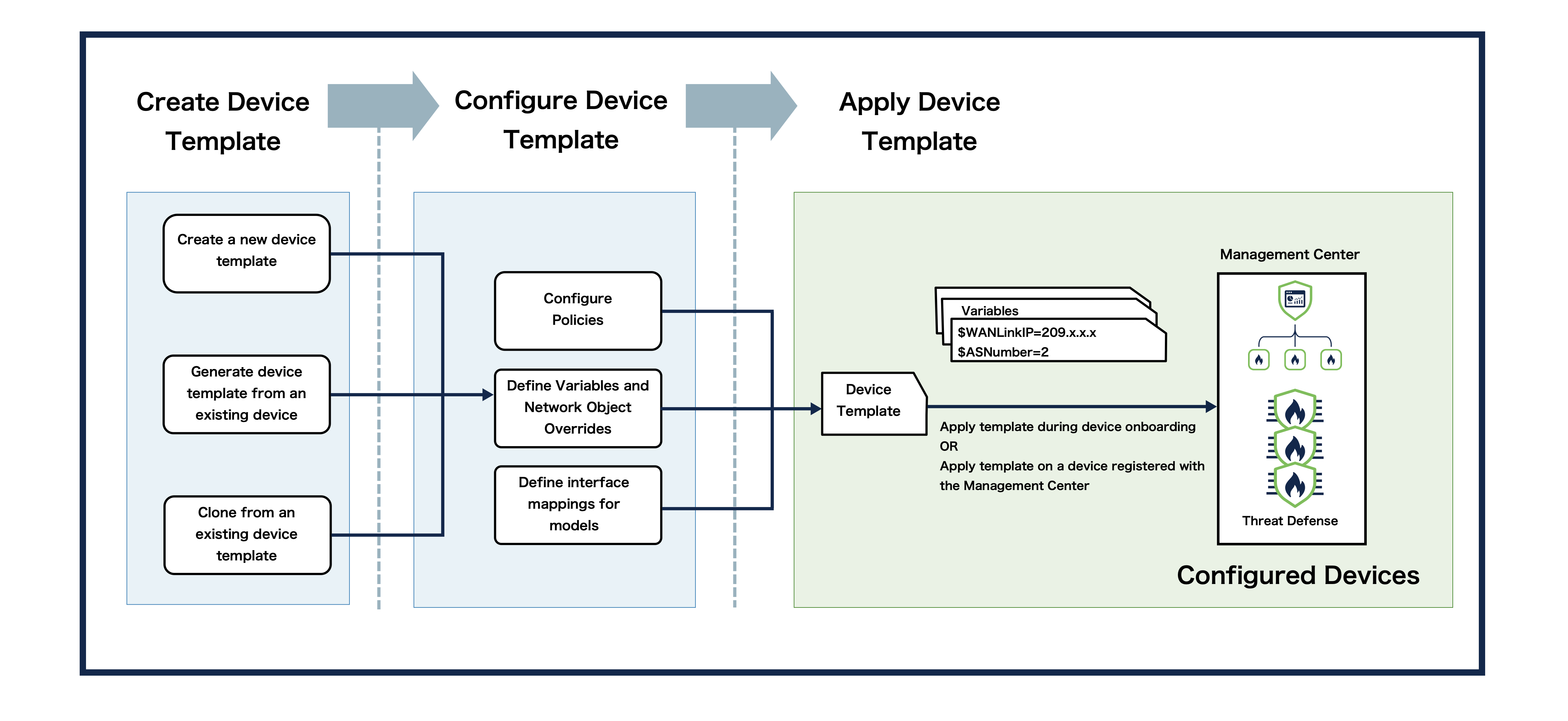
Device templates enable deployment of multiple branch devices with pre-provisioned initial device configurations. You can use device templates to perform bulk zero-touch provisioning of multiple devices, apply day 2 configuration changes to multiple devices with different interface configurations, and clone configuration parameters from existing devices. You can also register more than one device at a time with the Management Center using serial numbers.

When you register a device using basic initial configuration, you can apply limited configurations such as the access control policy and licenses. You must then configure other device settings such as interfaces, routing, and site-to-site VPN configurations individually after device registration. Device templates let you pre-configure these settings and more so you can apply them at the time of registration. Values that need to be unique per device, such as IP addresses, can be defined using variables and network object overrides that you define at registration.

You can also configure site-to-site VPN connections in a device template. These configurations define the site-to-site VPN topologies that a device should be a part of. The VPN configurations along with the other device template policies and configurations enable easy deployment of the branch device to your network. Device templates support the configuration of a device only as a spoke. A device can be part of multiple hub and spoke site-to-site VPN topologies.

After the configured device template is applied to a device, the variables are resolved, the protected network overrides are configured, and the device is added as a spoke in the specified VPN topology.

Methods to Register Devices using Templates

You can use device templates with the following methods to register the device on the management center and set up day 0 configuration:

  • Registration Key - You can register a single device by specifying the registration key and defining variables in the management center.

  • Serial Number - You can use zero-touch provisioning to register one or more devices by serial number. For serial number registration, define all variables and overrides in a CSV file that you upload.

Variables and Network Object Overrides

You can parameterize template configurations using variables and network object overrides.

A variable is an object type that is supported for template configurations. A variable in a template defines specific configuration values for a device. You can define values for these variables during device registration and during application of the template on the device. You can see the variable icon (x) for the fields that use a variable. The variables are displayed with a $ prefix to distinguish these values from the other values.

For information on supported variable types and creating variables, see Supported Variables and Add a Variable.

Network object overrides are similar to variables. But, these are used to provide override values for a network object. You can declare a list of network objects in the template and create network object overrides for these objects. You can then provide values for these network object overrides during the application of the template on the device. For example, if you define a host network object in a template, you can add a network object override before the application of the template on the device and then provide a relevant value during the application of the template on the device.

For more information on supported network objects and adding a network object override, see Supported Network Object Overrides and Add a Network Object Override.

Model Mapping

As interface configurations vary for different device models, the interface configurations in the template have to be copied to the target interfaces on the device. Model mapping enables you to define mapping of interfaces defined in the template to the interfaces of the required threat defense model. During application of the template on the device, the variables in the interface configurations are replaced with the values that you provide and copied to the mapped interfaces on the device. Note that you have to create the model mappings in the template before initiating application of the template on the device. For more information on setting up model mapping, see Add Model Mapping.

Requirements and Prerequisites for Device Management using Device Templates

Model Support

Device templates are supported on On-Prem Management Center, cloud-delivered Firewall Management Center(cdFMC), with the following models running Secure Firewall version 7.4.1 and later versions:

  • Firepower 1000 series

  • Secure Firewall 1200 series

  • Firepower 2100 series (7.4.x only)

  • Secure Firewall 3100 series

Supported Domains

Any

User Roles

  • To create, modify, or delete templates:

    • Admin

    • Network Admin

  • To view the created templates:

    • Any

Prerequisites for VPN Connections in Device Templates

  • Configure site-to-site VPN topologies that must be used in the device template.

  • Ensure that you have configured all hub and VPN topology-related configurations such as authentication methods, IKE and IPsec policies.

  • Supported types of VPN hub and spoke topologies are:

    • Policy-based

    • Route-based

    • SD-WAN

  • Assign appropriate logical names and IP addresses to the interfaces of the threat defense devices. For example, use inside for the interface connected to the LAN, and outside for the interface connected to the internet or WAN.

  • Spoke devices must be version 7.4.1 and later.

Licenses for Device Management using Device Templates

  • Device templates does not have any specific license requirements.

  • License entitlements for the target device must be present in the Smart Licensing account.

  • To configure VPN connections in the template, the Essentials license must allow export-controlled functionality. Choose System > Licenses > Smart Licenses to verify this functionality in the management center.

  • When you apply a template on a device, note the following conditions for Secure Client licensing:

    Device with Secure Client License

    Template with Secure Client License

    Secure Client License after Device Template Application

    Yes

    Yes

    Template License

    Yes

    No

    Device License

    No

    Yes

    Template License

Guidelines and Limitations for Device Management using Device Templates

General Guidelines for Device Templates

  • All device configurations other than VNI and VTEP are supported.

  • You can attach shared policies and S2S VPN policies to a template. These policies are assigned during template application.

  • Templates can be applied on HA devices. However, application of device templates during HA device pair registration is not supported. You also cannot manage HA-related configurations such as failover links, standby IP addresses, and so on. For more information, see Device Template Operations on Threat Defense HA Devices.

  • Device template operations are supported only on the active management center. The standby peer does not support device template operations.

  • Ensure that the template names and device display names are not the same.

  • Ensure that you do not create or delete a template during device backup or restore operations.

  • After application of the template on the device, if the manager access is changed from management to data interface or vice-versa, you must re-establish the management connection with the device. Note that you cannot change the manager access interface during template application.

  • You can add a maximum of 250 device templates to the management center.

  • Templates that are created and configured for devices that are managed through the data interface cannot be used to register and apply to devices that are managed through the management interface.

  • Device registration and application of template does not come under the Change Management workflow. Only approved data, such as access policies, templates, template variables, network overrides declared in template, and template configurations used in the template application operation are used.

  • Device registration with serial number and access control policy is supported for only one device at a time.

  • Devices with IPv6 DHCP discoverability are not supported when you add devices using serial numbers.

  • When you apply a template to a device that is already registered, the configuration in the template is only copied to the target device. You can then choose to manually deploy the configuration on the device or let the copied configuration stay on the device and deploy later. However, if you apply the template during device onboarding, the configuration in the template is copied to the target device and, as per existing behavior, automatically deployed on the device after device registration.

  • Any change in model mapping causes the device to be marked as ‘Out of Sync’. Consider reapplying the template to the devices if you have made changes to the interface mapping in the corresponding model mapping or if you have made any configuration changes after the previous application of the template.

  • Device templates are only supported on merged management and diagnostic interfaces. For more information, see Merge the Management and Diagnostic Interfaces.

  • Template configuration updates are supported by change management. Creation and application of device templates is not supported by change management.

  • You cannot sync configuration changes from a device to the template. A few sample scenarios during which you may want to make changes to the device configuration using a template along with recommended solutions are given below:

    • If you want to test the new configuration changes on one device before propagating the changes to multiple devices, we recommend that you make the changes in the template and apply the template to one device. Validate the changes on that device and then apply the template to the other devices.

    • If you want to make a large number of changes resulting in a signification deviation from the current configuration on a device, and then propagate those changes to other devices, you may choose one of the following options:

      • Export the current template to get a copy of the template. You can then make the required changes in the template and apply to a single device. Validate the changes on that device and then apply the template to the other devices.

      • You can also make the required changes on the device and create a template from that device. You can then apply and validate the changes on the other devices. However, we do not recommend this as template parameters such as variables and network object overrides will not be present in the created template.

    • If the configuration on a particular device starts to differ significantly from the configuration in the template, you may also choose to not use the template for this device and delete the device-template association from the Associated Devices window.

Guidelines for VPN Connections in Device Templates

  • Supported interfaces for VPN topologies are:

    Topology Type

    Interface Type

    Policy-Based and SD-WAN

    • Physical interfaces

      • Non-management

      • Interface Mode must be either Routed or None

    • Subinterfaces

    • Redundant interfaces

    • Etherchannel interfaces

    • VLAN interfaces

    Route-Based

    Static Virtual Tunnel Interfaces

  • When you apply a template on a device that is part of a VPN topology, you must ensure that the template includes interface configurations for all interfaces used in the topology.

  • When you apply a template with VPN connections to multiple devices, note the following:

    A template is applied to multiple devices in the order in which you have selected the devices. If the template has VPN connections, the corresponding VPN topology is locked.

  • For SD-WAN topology VPN connections: Ensure that IP address subnet of the interface does not conflict with the subnet of the IP address pool of the SD-WAN hub.

  • Domain:

    • You can define a template in a global or leaf domain. However, you can define a VPN topology only in a leaf domain.

    • You can configure VPN connections in a template for all domains. During template application, VPN connections are applied to the device only if the device is in the same domain as the VPN topology.

    For more information, see Device Templates in Domains.

  • Change management: Before you apply a device template to a device, ensure that the VPN topology is not locked by a Change management ticket.

Limitations for Device Templates

  • The following features and configurations are not supported using device templates:

    • Multi-instance mode

    • Clustering

    • Non-converged management interface

    • Transparent mode

    • HA failover configurations

    • Chassis configurations

    • Logical devices

    • Variables for nested objects

    • Override support for network groups and other object types

Limitations for VPN Connections

  • When you create a template from a device that is part of a VPN topology (Devices > Device Management > More (more icon) > Generate Template from Device), VPN configurations are not part of the template. You must reconfigure the VPN configurations on the template.

  • When you export a device template with one or more VPN connections (Template Settings > General > General pane > Export), the VPN connections are not exported. You must reconfigure the VPN connections on the imported template.

  • Certificate-based authentication:

    • Device templates do not support automatic certificate enrolment of a device.

    • When you onboard a device using a template with VPN configurations, if the VPN topology uses certificate-based authentication, the first deployment to the device will fail. Ensure that you manually enroll the device certificate after the device registration and deploy the configurations on the device again.

Template Management

Choose Devices > Template Management to bring up the Template Management window. This window provides you with a range of information and options to manage templates. All the created device templates are listed on this window.

Information on each template is provided under the following columns:

  • Name - Displays the name of the template.

  • Domain - Displays the domain in which the template is present.

  • Variables - Displays the variables and network object overrides in the template.

  • Access Control Policy - Click the link in the Access Control Policy column to view the policy that is deployed on the device.

  • Model Interface Mapping – Displays the device model interfaces that are mapped to the template interfaces.

Against each template, there is an Edit (edit icon) icon and a More (more icon) icon. When you click the Edit (edit icon) icon, the Device Management window appears with several tabs. You can use the tabs to configure interfaces, inline sets, routing, DHCP, VPN, and template settings.

Click the More (more icon) icon for the following options:.

Workflow for Device Management using Device Templates

Add a Device Template

You can add a new device template with the required configuration or generate a device template from an existing device.

Create a New Device Template

You can specify the device template name, description, access control policy, and routing mode. You can add more configurations after the template has been created. Perform the procedure given below to create a device template.

Procedure


Step 1

Choose Devices > Template Management.

Step 2

Click Add Device Template.

Step 3

In the Add Device Template window, enter a Name for the template.

Step 4

(Optional) Enter a Description for the template.

Step 5

Choose an Access Control Policy from the drop-down list.

Step 6

Choose a Mode from the drop-down list.

Step 7

Click OK.


Generate a New Device Template from an Existing Device

You can generate a new device template from a device that is registered with the management center. The new template has the same configuration as the device from which it is generated. You can generate a new device template from standalone and HA devices. However, if you generate a template from HA devices, the new template will not contain the failover configurations.

Perform the procedure given below to generate a new device template from an existing device.

Procedure


Step 1

Choose Devices > Device Management.

Step 2

Click the More (more icon) icon, and click Generate Template from Device.

Step 3

In the Generate template from device window, enter a Name for the template.

Step 4

(Optional) Enter a Description for the template.

Step 5

Choose an Access Control Policy from the drop-down list.

Note


This policy is assigned to the generated template. Any other shared policies that are associated with the device from which the template is generated are assigned to the generated template only if these policies are visible in the domain in which the template is being generated.

Step 6

Click OK. You can view the status of template creation in the Notifications > Tasks window.

Step 7

Choose Devices > Template Management to view the newly created template.


Import a Device Template

You can import a template into the management center or export a template to your local system. This feature is useful in the following scenarios:

  • Generate a copy of the template from a device, export it, and import that template into another management center or cloud-delivered Firewall Management Center.

  • Generate a copy of the template, export it, modify as required to create a variation of the existing template, and import the template into the management center.

  • Generate a copy of the template, export it, and import that template into another domain in which the source template is not visible.

When you import a template into a domain, any objects that are part of the configuration are either newly created or reused if the objects with the same name are visible in the domain into which the template is imported. Any object with matching names that is not visible, due to domain hierarchy, is imported as a new object with the name suffixed with a _x.

If there is a mismatch in the variable names when you want to onboard devices in a domain using the cloned template from another domain, you must specify the new variable names in the .csv file to onboard the devices.

Perform the procedure given below to import a device template into the management center from your local system.

Procedure


Step 1

Choose Devices > Template Management.

Step 2

Click the More (more icon) icon for the template that you want to replace with an imported template.

Step 3

Click Import and click Import again.

If you want to export a template, click Export and click OK.

Step 4

View the status of the import task in the Notifications > Tasks window.

Step 5

Choose the template SFO file on your local system and click Open. This template SFO file that you import can be newly created, generated from a device, or cloned from an existing template.

Step 6

View the status of the import task in the Notifications > Tasks window. You will see a notification informing you that the import or export task is successfully completed. If you are exporting a template, click Download Export Package in the Notifications > Tasks window to download the template configuration as an SFO file.

Note


Alternatively, you can also go to the Template Management window and click the Edit (edit icon) icon of the template. Then, go to Template Settings > General, and click Import or Export in the General tile to import or export the template.


Configure a Device Template

After creating the template, you can set up device configurations and configure settings that you want to apply on the device by editing the template.

Add a Physical Interface

By default, a device template will enable the device to come up with the following physical interfaces:

  • Management interface

  • Inside interface

  • Outside interface

Perform the procedure given below to create a physical interface.

Procedure


Step 1

Choose Devices > Template Management.

Step 2

Click the Edit (edit icon) icon of the template in which you want to add the physical interface.

Step 3

In the Interfaces tab, click Add Physical Interface.

Step 4

Choose a Slot and Port Index number from the drop-down list.

Step 5

Click Create Interface.


Add a Logical Interface

You can create a logical interface in the same way as you do on the management center without using the template. Perform the procedure given below to create a logical interface.

Procedure


Step 1

Choose Devices > Template Management.

Step 2

Click the Edit (edit icon) icon of the template in which you want to add the logical interface.

Step 3

In the Interfaces tab, click Add Interface, and choose the type of interface that you want to create from the drop-down list. You can create the following types of interfaces:

  • Sub-interface

  • Ether channel interface

  • Bridge group interface

  • VLAN interface

  • Virtual tunnel interface

  • Loopback interface

For more information, see Interface overview and Regular Firewall Interfaces.


Edit an Interface

You can edit an interface in the same way as you do on the management center without using the template. Use template variables to set up the IPv4 and IPv6 addresses. The device template supports the configurations that are supported on Firepower 1000,Secure Firewall 1200, Firepower 2100, and Secure Firewall 3100 Threat Defense devices. Perform the procedure given below to edit an interface.

Procedure


Step 1

Choose Devices > Template Management.

Step 2

Click the Edit (edit icon) icon of the template in which you want to edit the physical interface.

Step 3

In the Interfaces tab, click the Edit icon for the interface that you want to edit.

Step 4

In the Edit Physical Interface window, you can edit any of the following settings:

  • General

  • PoE

  • IPv4

  • IPv6

  • Path Monitoring

  • Hardware Configuration

  • Manager Access

  • Advanced

Note


Use variables to configure IPv4 and IPv6 addresses. For more information on templatizing variables, see Configure Template Parameters.

For more information on editing the settings mentioned above, see Interface overview and Regular Firewall Interfaces.


Configure Other Device Settings

Configure the other device settings in the same way as you do on the management center without using the template.

Procedure


Step 1

Choose Devices > Template Management.

Step 2

Click the Edit (edit icon) icon for the template in which you want to configure the settings.

Step 3

Click the tabs at the top of the window to configure any of the following settings:

  • Inline Sets

  • Routing

  • DHCP

  • VPN

  • Template Settings


Configure Template Settings

These are template-specific settings that are copied to the device when the template is applied on the device. In the Template Settings window, you can configure the following template settings:

Edit General Settings

In the General tile, you see the following fields:

  • Template Name – The name of the template.

  • Transfer Packets – Displays whether or not the managed device sends packet data with the events to the management center.

  • Mode – Displays the mode of the management interface for the device: routed.

  • Configuration – Click Export to export the template configurations as an SFO file. Click Import to import an SFO file that has the template configurations that you require.

  • Manage device by Data Interface – Toggle the button to enable or disable management of the device using the data interface.

Perform the procedure given below to edit the name of the device, and to enable or disable packet transfer.

Procedure

Step 1

Click the Edit (edit icon) icon in the General tile.

Step 2

Change the Template Name as per your requirement.

Step 3

Check the Transfer Packets checkbox to allow packet data to be stored with events on the management center.

Step 4

Click Save.


Edit Licenses

In the License tile, you can see the License types that are required based on the configurations used in the template. Choosing a license here does not consume that license on the device. The license is consumed only when you apply the template to a device.

Perform the procedure given below to edit the license types as per your requirement.

Procedure

Step 1

Click the Edit (edit icon) icon in the License tile.

Step 2

Check or clear the check box next to the license you want to enable or disable for the managed device.

Step 3

Click Save.


Edit Applied Policies

In the Applied Policies tile, you can see the access control policies that are associated with the template.

For policies with links, you can click the link to view the policy.

Perform the procedure given below to edit the policy assignments as per your requirement.

Procedure

Step 1

Click the Edit (edit icon) icon in the Applied Policies tile.

Step 2

For each policy type, choose a policy from the drop-down list. Only existing policies are listed.

Step 3

Click Save.


Edit Advanced Settings

The Advanced Settings tile displays the advanced configuration settings, as described below. You can edit any of these settings.

Table 1. Advanced Section Table Fields

Field

Description

Application Bypass

The state of Automatic Application Bypass on the device.

Bypass Threshold

The Automatic Application Bypass threshold, in milliseconds.

Object Group Search

The state of object group search on the device. While operating, the threat defense device expands access control rules into multiple access control list entries based on the contents of any network or interface objects used in the access rule. You can reduce the memory required to search access control rules by enabling object group search. With object group search enabled, the system does not expand network or interface objects, but instead searches access rules for matches based on those group definitions. Object group search does not impact how your access rules are defined or how they appear in the management center. It impacts only how the device interprets and processes them while matching connections to access control rules.

Note


By default, the Object Group Search is enabled when you add threat defense for the first time in the management center.

Interface Object Optimization

The state of interface object optimization on the device. During deployment, interface groups and security zones used in the access control and prefilter policies generate separate rules for each source/destination interface pair. If you enable interface object optimization, the system will instead deploy a single rule per access control/prefilter rule, which can simplify the device configuration and improve deployment performance. If you select this option, also select the Object Group Search option to reduce memory usage on the device.

Perform the procedure given below to edit the advanced settings.

Procedure

Step 1

Click the Edit (edit icon) icon in the Advanced Settings tile.

Step 2

You can change the settings as per your requirement. For more information, see the following sections:

Step 3

Click Save.


Edit Deployment Settings

The Deployment Settings tile displays the information described in the table below.

Table 2. Deployment Settings

Field

Description

Auto Rollback Deployment if Connectivity Fails

Enabled or Disabled.

You can enable auto rollback if the management connection fails as a result of the deployment; specifically if you use data for management center access, and then you misconfigure the data interface.

Connectivity Monitor Interval (in Minutes)

Shows the amount of time to wait before rolling back the configuration.

Deployment settings include enabling auto rollback of the deployment if the management connection fails as a result of the deployment; specifically if you use data for management center access, and then you misconfigure the data interface. You can alternatively manually roll back the configuration using the configure policy rollback command.

Perform the procedure given below to edit the deployment settings.

Procedure

Step 1

Click the Edit icon in the Deployment Settings tile.

Step 2

Set the Connectivity Monitor Interval (in Minutes) to set the amount of time to wait before rolling back the configuration. The default is 20 minutes.

Step 3

If a rollback occurs, see the following for next steps.

  • If the auto rollback was successful, you see a success message instructing you to do a full deployment.

  • You can also go to the Deploy > Advanced Deploy screen and click the Preview icon to view the parts of the configuration that were rolled back (see Deploy Configuration Changes). Click Show Rollback Changes to view the changes, and Hide Rollback Changes to hide the changes.

  • In the Deployment History Preview, you can view the rollback changes.

Step 4

Check that the management connection was reestablished.

In management center, check the management connection status on the Devices > Device Management > Device > Management > FMC Access Details > Connection Status page.

At the threat defense CLI, enter the sftunnel-status-brief command to view the management connection status.

If it takes more than 10 minutes to reestablish the connection, you should troubleshoot the connection. See Troubleshoot Management Connectivity on a Data Interface.


Configure Template Parameters

You can templatize configurations using template parameters such as variables and network object overrides.

Supported Variables

The following variable types are supported in device templates.

Variable Name

Description

Type

AS Number Defines the unique Autonomous System (AS) number.

Integer

Example: 2

FQDN Defines a single Fully Qualified Domain Name (FQDN).

String

Example: abc.example.com

IPv4 Host Defines the IPv4 address of the host.

String

Example: 209.165.201.8

IPv4 Network Defines the IPv4 network address block.

String

Example: 209.165.200.224/27

IPv4 Range Defines the range of IPv4 addresses.

String

Example: 209.165.200.225-209.165.200.250

IPv6 Host Defines the IPv6 address of the host.

String

Example: 2001:DB8::1

IPv6 Network Defines the IPv6 network address block.

String

Example: 2001:DB8:0:CD30::/60

Password Defines a password string.

String

Example: E28@2OiUrhx!

Router ID Defines an identifier for the router.

Integer

Example: 21

String Defines a custom string.

String

Example: testvalue2

Add a Variable

Perform the procedure given below to add a variable.

Procedure

Step 1

Choose Objects > Object Management.

Step 2

Choose Variable from the list of object types.

Step 3

Click Add Variable.

Step 4

Enter a Name.

In a multi-domain deployment, object names must be unique within the domain hierarchy. The system may identify a conflict with the name of an object you cannot view in your current domain.

Step 5

Choose a Variable Type from the drop-down list.

Step 6

(Optional) Enter a Description.

Step 7

Click Save.


Supported Network Object Overrides

The following network objects are supported.

Network Object Name

Description

Type

Network An address block, also known as a subnet.

String

Example:

IPv4 - 209.165.200.224/27

IPv6 - 2001:DB8::/48

Host The IP address of the host.

String

Example:

IPv4 - 209.165.200.225

IPv6 - 2001:DB8:1::1

Range A range of IP addresses.

String

Example:

IPv4 - 209.165.200.225-209.165.200.250

IPv6 - 2001:DB8::1 - 2001:DB8:FFFF:FFFF:FFFF:FFFE:FFFF:FFFF

FQDN A single fully-qualified domain name (FQDN).

String

Example: abc.example.com

Add a Network Object Override

Perform the procedure given below to add a network object override.

Procedure

Step 1

Choose Devices > Template Management.

Step 2

Click the Edit (edit icon) icon of the template in which you want to add the network object override.

Step 3

Choose Template Settings > Template Parameters.

Step 4

In the Network Object Overrides section, click Add or Remove Network Object Overrides.

Step 5

In the Add or Remove Network Object Overrides window, choose the network objects for which you want to create network object overrides from the Available Networks window and click the > button.

Step 6

Click Save.


Add Model Mapping

For each model, you can specify which template interface corresponds with which model interface. You can map a template to one or more models as long as the interface configurations are valid for all mapped models. For example, if the template includes switch ports and VLAN interfaces, then that template can only be applied to a Firepower 1010 or Secure Firewall 1210/1220.

Perform the procedure given below to add model mapping.

Procedure

Step 1

Choose Devices > Template Management.

Step 2

Click Add Model Mapping for the template in which you want to create the model mapping. Alternatively, you can click the Edit (edit icon) icon of the template and choose Template Settings > Model Mapping.

Step 3

Click Add Model Mapping.

Step 4

Choose the Device Model from the drop-down list.

Step 5

Map the template interfaces to the device model interfaces by choosing the interface from the Model Interface drop-down list.

Note


You can click Clear Mapping to remove the defined model mapping. Click Reset Mappings for default interface mapping in which the mapping is done based on the slot and port index order of the interface names.

Step 6

Click Save. The interface mappings are listed along with the device model and mapping status on the Model Mapping window.

Note


Some configurations in the template may not be supported on all device models. Unsupported configurations, if any, are not applied to the device. The Device Template Apply Report provides details about such configurations.


Invalid Model Mappings

Some configurations in the template may not be supported on all device models. Unsupported configurations, if any, are not applied to the device. Valid model mappings can also become invalid when you modify template configurations. For example, when you add a new interface on the template and assign a name to it, the new interface must be mapped to the appropriate interface on the device model.

Model mapping can also be invalidated due to any of the following reasons:

  • Number of configured VRF instances exceeds the limit for a specific model.

  • Interfaces mapped to incompatible models, versions, or interfaces. See Requirements and Prerequisites for more information.

  • Number of interfaces exceeds the model limit.

  • Deleted an interface that was mapped.

  • Newly added physical interfaces are not mapped to a compatible model interface.

  • Model mapping is not done for a named interface.

  • Model mapping is not done for an interface related to other logical interfaces, such as sub-interfaces, PC interfaces, and so on.

  • Making policy or configuration changes that are unsupported on some device models. For example, enabling switch port configuration on interfaces.

You can also save a template with invalid model mappings. However, you must review and fix the model mapping before initiating application of the template on the device.

You can hover over Invalid under Mapping Status to view the errors that caused the invalid mapping status. Fix the errors before initiating application of the template on the device.

Configure Site-to-Site VPN Connections in a Device Template

Device Template with Site-to-Site VPN Connections Workflow

Configure an SD-WAN VPN Connection

You can configure an SD-WAN VPN connection to add spokes to SD-WAN topologies using the device template.

Before you begin

Procedure


Step 1

Choose Devices > Template Management.

Step 2

Click the edit icon adjacent to the device template that you want to edit.

Step 3

Click the VPN tab.

Step 4

Click Add VPN Connection.

Step 5

Choose an SD-WAN topology from the VPN Topology drop-down list.

The Add VPN Connection dialog box expands and you can configure the following parameters:

  1. From the VPN Interface drop-down list, choose a WAN-facing or internet-facing physical interface to establish a VPN connection with the hub.

    This list contains all the interfaces configured on the device template.

  2. Use IP Address from the VPN Interface—This drop-down list is auto populated with the IP address variable. For IPv6 addresses, choose an IPv6 address from the drop-down list.

  3. Check the Local Tunnel (IKE) Identity check box to enable a unique and configurable identity for the VPN tunnel from the spoke to a remote peer.

  4. Identity Type—Key ID is the only supported identity type. Choose a key ID variable from the drop-down list or click (add icon) to create a new key ID variable.

  5. Click OK.

    You can view the VPN connection in the Site-to-Site VPN Connections table.

Step 6

Click Save.


What to do next

  1. Configure the routing policy for the spoke in the device template.

  2. Map the device interfaces to the template interfaces (Model Mapping).

  3. Apply the template to a device.

Configure a Route-Based Site-to-Site VPN Connection

You can configure a route-based site-to-site VPN connection to add spokes to route-based site-to-site VPN topologies using the device template.

Before you begin

Procedure


Step 1

Choose Devices > Template Management.

Step 2

Click the edit icon adjacent to the device template that you want to edit.

Step 3

Click the VPN tab.

Step 4

Click Add VPN Connection.

Step 5

Choose a route-based site-to-site VPN topology from the VPN Topology drop-down list.

The Add VPN Connection dialog box expands and you can configure the following parameters:

  1. From the Virtual Tunnel Interface (VTI) drop-down list, choose a VTI interface or click (add icon) to create a new VTI.

    VTI is a virtual interface used to establish a route-based VPN tunnel. You must configure routing policies for a VTI to set up a VPN tunnel. This list contains all the VTIs configured on the device template. For more information on creating a VTI, see Add a VTI Interface.

  2. Check the Use Public IP Address check box to override the tunnel source IP address and configure a public IP address variable for the VTI. Click (add icon) to create a new public IP address variable.

    This IP address is the source IP address for the VPN tunnel. By default, this is the IP address of the VPN interface. However, if the device is behind NAT, the VPN interface has a private address, but the post-NAT public IP address should be configured.

  3. Check the Local Tunnel (IKE) Identity check box to enable a unique and configurable identity for the VPN tunnel from the spoke to a remote peer.

  4. Identity Type: Key ID is the only supported identity type. Choose a key ID variable from the drop-down list or click (add icon) to create a new key ID variable.

  5. (Optional) Check the Enable Secondary VPN Tunnel check box to configure the parameters for the secondary VPN tunnel.

  6. Click OK.

    You can view the VPN connection in the Site-to-Site VPN Connections table.

Step 6

Click Save.


What to do next

  1. Configure the routing policy for the spoke in the device template.

  2. Map the device interfaces to the template interfaces (Model Mapping).

  3. Apply the template to a device.

Configure a Policy-Based Site-to-Site VPN Connection

You can configure a policy-based site-to-site VPN connection to add spokes to policy-based site-to-site VPN topologies using the device template.

Before you begin

Procedure


Step 1

Choose Devices > Template Management.

Step 2

Click the edit icon adjacent to the device template that you want to edit.

Step 3

Click the VPN tab.

Step 4

Click Add VPN Connection.

Step 5

Choose a policy-based site-to-site VPN topology from the VPN Topology drop-down list.

The Add VPN Connection dialog box expands and you can configure the following parameters:

  1. From the VPN Interface drop-down list, choose a WAN-facing or internet-facing physical interface to establish a VPN connection with the hub.

    This list contains all the interfaces configured on the device template.

    Do one of the following to configure the IP address of the VPN interface:

    • Click the Use IP Address from the VPN Interface radio button to use the IP address of the VPN interface.

      This IP address is auto populated. For IPv6 addresses, choose an IPv6 address from the drop-down list.

    • Click the Use Public IP Address radio button to configure a public IP address for the VPN interface.

      Choose an IP address variable from the drop-down list or click (add icon) to add an IP address variable.

  2. Check the Local Tunnel (IKE) Identity check box to enable a unique and configurable identity for the VPN tunnel from the spoke to a remote peer.

  3. Identity Type: Key ID is the only supported identity type. Choose a key ID variable from the drop-down list or click (add icon) to add a new key ID variable.

  4. Protected Networks: Click (add icon) to configure a protected network for the VPN connection.

    Do one of the following:

    • Choose a protected network and click OK.

    • Click Add to configure a network object and click Save.

      When you create a protected network object, note the following:

      • Click either the Host or the Network radio button.

      • Check the Allow Overrides check box.

  5. Click OK.

    You can view the VPN connection in the Site-to-Site VPN Connections table.

Step 6

Click Save.


What to do next

  1. Note that before you apply a template to a device, to configure device-specific values for the protected networks, add these objects in Template Settings > Template Parameters > Add Network Objects Overrides.

  2. Map the device interfaces to the template interfaces (Model Mapping).

  3. Apply the template to a device.

Register a Device Using Device Template and Add it to a Route-Based VPN Topology

This section provides instructions to register a device using device template and add it to a route-based VPN topology.

Before you begin

Ensure that you have a route-based VPN topology.

Step

Task

GUI Path

More Information

1

Create a device template.

Devices > Template Management > Add Device Template

Create a New Device Template

2

Configure interfaces in the template.

Devices > Template Management > Interfaces

Edit an Interface

3

Configure a route-based VPN connection in the template.

Devices > Template Management > VPN > Add VPN Connection

Configure a Route-Based Site-to-Site VPN Connection

4

Configure routing policies in the template.

Devices > Template Management > Routing

5

Add a model mapping for the device model in the template.

Devices > Template Management > Template Settings > Model Mapping

Add Model Mapping

6

Register the device using a device template.

Devices > Device Management > Add > Device (Wizard)

Add a Device Using a Registration Key—Device Template

7

Deploy configurations on the hub of the VPN topology.

Deploy

Add a Device to an SD-WAN Topology in a Dual ISP Deployment

This section provides instructions to add a device to an SD-WAN topology in a dual ISP deployment using a device template.

Before you begin

Ensure that you have two SD-WAN VPN topologies with the same hub. For more information about configuring SD-WAN topologies, see Configure an SD-WAN Topology Using the SD-WAN Wizard.

Step

Task

GUI Path

More Information

1

Create a device template.

Devices > Template Management > Add Device Template

Create a New Device Template

2

Add a physical interface in the template.

By default, a template has only one outside interface. Rename the outside interfaces, for example, ISP1, ISP2.

Devices > Template Management > Interfaces > Add Physical Interface

Add a Physical Interface

3

Configure an SD-WAN VPN connection using ISP1 interface.

Devices > Template Management > VPN > Add VPN Connection

Configure an SD-WAN VPN Connection

4

Configure an SD-WAN VPN connection using ISP2 interface.

5

Add static routes from ISP1 and ISP2 interfaces to the SD-WAN hub network.

Devices > Template Management > Routing > Static Route

-

6

Add the ISP1 and ISP2 interfaces to an ECMP zone.

Devices > Template Management > Routing > ECMP

-

7

Configure the network object overrides.

Devices > Template Management > Template Settings > Template Parameters > Add Network Objects Overrides

Add a Network Object Override

8

Map the template interfaces to the device model interfaces (Model Mapping).

Devices > Template Management > Template Settings > Model Mapping

Add Model Mapping

9

Apply template to the device.

Devices > Template Management >

Apply a Template

10

Deploy configurations on the device.

Deploy

11

Deploy configurations on the hubs of the SD-WAN topologies.

Deploy

For more information about dual ISP deployment using the SD-WAN wizard, see Sample Configurations for Dual ISP Deployment Using SD-WAN Wizard.

Add a Device to the Management Center Using a Device Template

You can add a device to the management center using a device template with of the following options:


Note


Any change management tickets related to template configurations must be approved for the corresponding changes to be incorporated into the template application workflow. Only approved template configurations are used during template application.


Apply Templates to Existing Devices

You can apply or reapply a template to existing devices.

Apply a Template

You can apply a template to devices that are already registered with the management center. Application of a template on a device clears existing configurations and applies configurations from the template. However, the threat defense HA failover configurations are not cleared.

Application of a template changes device configurations only on the management center. You must explicitly deploy these device configuration changes to the threat defense device. You cannot roll back the applied configuration changes. However, you can apply another template with the required configurations.


Note


Any change management tickets related to template configurations must be approved for the corresponding changes to be incorporated into the template application workflow. Only approved template configurations are used during template application.


Perform the procedure given below to apply the template on existing devices.

Procedure


Step 1

To apply the template from the Template Management window, choose Devices > Template Management.

  1. Click the More (more icon) icon next to the template that you want to apply, and click Apply.

  2. From the Device dropdown list, choose the Device on which you want to apply the template.

  3. Click Confirm to initiate application of template on the device.

Step 2

(Optional) To apply the template from the Associated Devices window, choose Devices > Template Management.

  1. Click the Edit (edit icon) icon of the template that you want to apply to a device.

  2. Click Associated Devices.

  3. In the Associated Devices window, click Apply Template.

  4. From the Device drop-down list, choose the Device on which you want to apply the template.

  5. Enter values for the Variables and Network object overrides fields.

  6. Click Apply to initiate application of template on the device.


Reapply a Template

If you make any changes to the device or template that results in the configuration being out-of-sync, you can reapply the template to make the configuration in sync with the template.

Perform the procedure given below to reapply the template on a device.

Procedure


Step 1

Choose Devices > Template Management.

Step 2

Click the Edit (edit icon) icon of the template that you want to reapply to a device.

Step 3

Click Associated Devices.

Step 4

In the Associated Devices window, click Reapply Template for the device on which you want to reapply the template.

Note


If you want to reapply the template on all the associated devices in the template, click Bulk Reapply and click Confirm.

Step 5

On the Reapply template window, you can reuse the autopopulated Variables and Network object overrides values or enter new values.

Step 6

Click Confirm to initiate reapplication of the template on the device.


Validation of Template Configuration Before and After Application of Template on Device

Validation of template configuration is done before and after application of the template on the device.

The following validation checks are performed at the start of the task to apply the template on the device:

  • Ensure that the target device model and version are supported.

  • Cluster and container checks -The device must not be part of a cluster or multi-instance.

  • Model mapping validation - Model mapping for the target device model exists and is valid.

  • Sanity check of template parameter values. For example, two variables used as IP addresses of interfaces must not have the same value.

The following validation checks are performed at the end of the task to apply the template on the device to ensure that the applied configurations are valid:

  • Interface configuration validation. For example, variables used for the IP address fields of two or more interfaces must not have the same IP address values.

  • Routing policy validation. For example, the IPv4 address in BGP neighbor configurations must not overlap with the IP address of any interface.

If the validation checks that are done at the end of the task to apply the template on the device fail, any applied configurations are rolled back and the device is restored to it’s original state.

Monitoring Device Templates

You can monitor and verify the application of templates by viewing the devices listed in the Associated Devices window and by viewing the Template Apply Report.

View Associated Devices

The devices that are associated with the templates are listed in the Associated Devices window. Each device row displays the Device Name, Sync Status, Template Application Status, and Applied Date. You can also click Reapply template to reapply the template. Click the Variable Summary icon to display a summary of the variables in the template and the Report (Report icon) icon to download the Device Template Apply report. Click the Delete (delete icon) icon to remove the template from the device.

Click Apply Template if you want to apply a template on a device from the Associated Devices window. If you want to reapply the template on all the associated devices in the template, click Bulk Reapply and click Confirm.

The Sync Status can be either Sync or Out-of-Sync. If the status is displayed as Sync, it indicates that the template and device configurations are the same or in sync. If the status is displayed as Out-of-Sync, it indicates that there has been a change in configuration either on the device or in the template since the last time that the template was applied..

The association of the device with the template is not altered by the following conditions:

  • Pending configuration changes on the device – The Sync Status does not change if there are pending configuration changes that have to applied on the device.

  • Deployment of pending configuration changes on the device – The Sync Status does not change after deployment of pending configuration changes on the device.

The table below shows the Sync and Out-of-Sync scenarios that may occur.

Device Configurations Modified After Application of Template on Device

Template Configurations Modified After Application of Template on Device

Association Status

No No In Sync
Yes No Out of Sync
No Yes Out of Sync
Yes Yes Out of Sync

Generate a Template Apply Report

A Template Apply Report PDF is generated after the task to apply the template is completed. This report is generated on both successful and unsuccessful application of the template on the device. You will see a link to this report in the Notifications > Tasks window.

The Template Apply Report contains the following details:

  • Template name

  • Device model name

  • Domain from which the template was applied

  • Start and end time

  • Status of the application of the template on the device

  • Interface mapping information

  • Variable values

There may be some configurations on the template that are not applied to the device due to incompatible device model or version. The report also contains details about such configurations. The report also contains any errors that are encountered when the application of the template fails. Application of a template on a device may fail due to any of the following reasons:

  • Model mapping does not exist for the device model that is used.

  • Values used for variables and network object overrides do not conform to routing policy or interface configuration rules. For example, the same IPv4 address has been used for two IPv4 address interface variables.

  • Device or template is locked due to some other task that is being executed, such as application or modification of the template.

Delete Device Template

Note that you cannot recover a template after deleting it. To backup template configurations, use the Export option explained in the Import a Device Template section. To delete a device template, perform the procedure given below.

Procedure


Step 1

Choose Devices > Template Management.

Step 2

Click the More (more icon) icon of the template that you want to delete.

Step 3

Click Delete.

Step 4

Click Delete again in the Confirm Deletion window.


Configure a Template for Threat Defense Devices Managed Using the Data Interface

To configure a template that you want to apply to a threat defense device that is managed using a data interface for management center connectivity, ensure that the connectivity parameters of the device match the template. This ensures that the Threat Defense device does not lose connectivity with the management center after application of the template. A template that you configure for threat defense devices managed using the data interface cannot be applied on devices that are not managed by the data interface.

The following is a list of connectivity parameters:

  • Data interface used to the manage the threat defense device. For example, Ethernet1/1.

  • Name of the interface. For example, outside.

  • IP address configured on the data interface. For example, DHCP or static IP.

  • Route configured for the data interface. This can be a default or specific route defined on the data interface used for connectivity between the threat defense device and the management center.

  • DDNS hostname configuration on the data interface.

If the connectivity parameters on the template do not match with the ones on the device, the template validation checks that are done to ensure that the template is successfully applied on the device will fail. The template is then not applied on the device. The template validation checks do not enforce an exact match for some parameters such as IP address or DDNS hostname. However, ensure that you configure such parameters to maintain connectivity between the threat defense device and the management center after deployment.

The following is a list of template validation checks done to ensure sanity of configurations that are required to manage the threat defense device using the data interface:

  • You cannot apply a template in which manager access to the device is configured with the management interface to a device in which manager access to the device is configured with the data interface.

  • You cannot apply a template in which manager access to the device is configured with the data interface to a device in which manager access to the device is configured with the management interface.

  • You cannot apply a template in which manager access to the device is configured with the single WAN data interface to a device in which manager access to the device is configured with the dual WAN data interface.

  • If any of the connectivity parameters do not match, you cannot apply a template in which manager access to the device is configured with the data interface to a device in which manager access to the device is configured with the data interface.

Perform the procedure given below to configure the template to manage threat defense devices using the data interface.

Procedure


Step 1

Choose Devices > Template Management.

Step 2

Click the Edit (edit icon) icon of the template that you want to configure to manage threat defense devices using the data interface.

Step 3

Click the Template Settings tab.

Step 4

In the General tile, toggle the Manage device by Data Interface button.

Step 5

You will see a popup asking you to pick a data interface for manager access. Click OK.

Step 6

Click the Interfaces tab.

Step 7

Click the Edit icon of the data interface that you want to use for manager access. The first data interface – Ethernet1/1 (outside interface), is the data interface that is most commonly used for manager access.

Step 8

In the Edit Physical Interface window, click the Manager Access tab.

Step 9

Check the Enable management access checkbox.

Step 10

Click OK. You will see that the interface that you selected for manager access has been marked with Manager Access.

Step 11

Click the DHCP tab.

Step 12

Click the DDNS Update Methods tab.

Step 13

Click +Add to add a DDNS update method.

Step 14

In the Add DDNS Update Method window, enter a Method Name and choose FMC only.

Step 15

Set the Update Interval as per your requirement.

Step 16

Click OK. You will see the method that you created in the DDNS Update Methods table.

Step 17

Click the DDNS Interface Settings tab.

Step 18

Click +Add to add dynamic DNS configuration.

Step 19

In the Add Dynamic DNS configuration window, choose values for the following fields:

  • Interface – Choose the interface enabled for manager access

  • Method Name – Choose the method that you created.

  • Host Name – Choose a variable for the hostname.

Do not edit the rest of the fields in this window.

Step 20

Click OK. The DDNS Interface Settings table is populated with the entry that you created.

Step 21

To configure the model mapping to ensure that the data interface set for manager access in the template matches the data interface selected for manager access on the device, click the Template Settings tab and click Model Mapping.

Step 22

Click Add Model Mapping.

Step 23

Choose the Device Model from the drop-down list.

Step 24

Map the date interface that is set for manager access in the template to the appropriate data interface on the device by choosing the interface from the Model Interface drop-down list.

Step 25

Click Save. The interface mappings are listed along with the device model and mapping status on the Model Mapping window. You can now apply the template on a device that is managed using the data interface.


Device Template Operations on Threat Defense High Availability Devices

You can apply device templates on threat defense High Availability (HA) devices after device registration. Failover configurations are not supported in device templates. Any failover configurations and monitored interfaces that are already part of the target HA device pair configurations are not modified. You cannot map any template interfaces to failover interfaces.

You can generate a device template from an HA device pair. Template operations such as application of template on device, template generation, import, and export of template, can be performed only on primary or active HA devices. You cannot perform these operations on secondary or standby devices.

Audit Logs

Logs related to application of the device template, configuration updates, device template creation, and deletion, are logged under audit logs. The device template audit logs are added to the log both at the start and at the end of the task to apply the template on the device.

An audit diff file is also generated that enables you to view configuration changes that have been done during application of the template on the device. Perform the procedure given below to view the diff file.

Procedure


Step 1

Choose System > Monitoring > Audit.

Step 2

The device template logs are logged under the subsystem Devices > Template Management. Click the diff icon to open a new window that displays the configuration changes that have been done during the application of the template on the device.


Device Templates in Domains

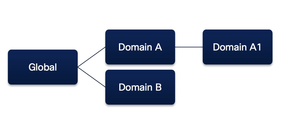
Device templates can exist in any domain. If you are in the child domain, you have read-only access to the templates above you in the domain hierarchy. You can apply a template to a device from its domain or its parent domains. You can generate a template from a device and apply that template to a device in any domain in the domain hierarchy.

A domain hierarchy sample is given below along with a table displaying the supported device template application and generation scenarios.

Consider the following scenario:

Device Templates and Domains
  • Domain A and B are child domains of the Global domain.

  • Domain A1 is the child domain of Domain A.

Template Domain Device Domain Device Template Application/Generation Supported
Global A1 Yes
Global B Yes
A A1 Yes
A B No
B A1 No
B B Yes
A1 A1 Yes
A1 B No

Domains and VPN Connections

  • You can define a template in a global or child/leaf domain. However, you can define a VPN topology only in a leaf domain.

  • You can configure VPN connections in a template for all domains. During template application, VPN connections are applied to the device only if the device is in the same domain as the VPN topology.

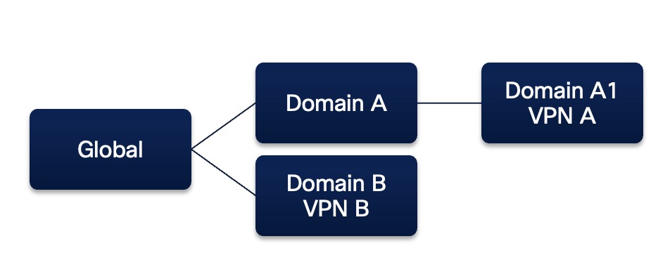
A domain hierarchy sample is given below along with a table displaying the supported device template application and generation scenarios.

Consider the following scenario:

VPN Connections in Device Templates and Domains
  • Domain A and B are child domains of the Global domain.

  • Domain A1 is the child domain of Domain A.

  • VPN A is part of Domain A1.

  • VPN B is part of Domain B.

Template Domain

VPN Topology in the Template

Device Domain Device Template Application/Generation Supported
Global

VPN A

VPN B

A1 No
Global

VPN B

B Yes
A

VPN A

A1 Yes
B

VPN B

A1 No
B

VPN B

B Yes
A1

VPN A

A1 Yes

Troubleshooting Device Templates

Initial Troubleshooting

For initial troubleshooting, we recommend looking at the information in the Template Apply Report and notifications that come up on the Management Center UI when you run into an error. The management center log files also contain detailed debugging and troubleshooting info.

Follow the procedure given below for initial troubleshooting.

  1. Check the errors mentioned in the Template Apply Report. For more information, see Template Apply Report.

  2. Review variable values and check for overlaps and incompatibilities.

  3. Check model mappings to ensure if the correct model mappings exist. Delete or add mappings accordingly.

  4. See the management center audit logs to find any other issues and resolve them.

Consider the following error scenario. In a device template, the inside interface is configured with a static IPv4 variable - $insideIPv4 .

The BGP IPv4 address is configured with an IPv4 BGP neighbor.

An overlapping IPv4 address is configured for the BGP neighbor and an interface.

Due to the issues mentioned above, the application of the device template fails and an error is displayed.

To troubleshoot this error, identify the error from the notification displayed on the UI.

IP Address 192.168.10.1 same as ip address of interface - 'inside'(Ethernet1/1)

Check the Template Apply Report for more information.

Enter correct values for the variables and apply the template again to ensure successful application of the template on the device.

Troubleshoot Device Registration

  • Issue: Admin Password is incorrect or not provided during registration

    Scenario: If the admin password is not set on the device and if you have not provided the admin password during registration, the threat defense device provisioning will fail. In such a scenario, a Provision Error along with an Enter Password link is displayed.

    Workaround: Click Enter Password to enter a new password and click Save. Click Confirm and Proceed to trigger the onboarding again.

  • If the admin password is already set on the device and you provide another admin password during registration, device provisioning will fail.

  • Issue: Device registration in management center fails

    Workaround: Follow existing device registration troubleshooting steps. For more information, see Configure, Verify, and Troubleshoot Firepower Device Registration.

  • Issue: Bulk Registration Request Fails in management center

    Scenario: The bulk registration request can fail due to a few scenarios:

    • You do not have the required permissions to perform template-related operations

    • Template is not visible from the request domain

    • Invalid CSV file provided

    Workaround: You can see logs for these errors in the VMS Shared and USM Shared log files. Fix the errors and initiate registration again.

  • Issue: Device provisioning fails in CDO due to some generic errors, such as communication with the device fails

    Workaround: Click Retry in the Provision Error to trigger the onboarding in CDO again. You can also see the CDO workflows for more information on the error and troubleshooting information.

Troubleshoot Cisco Security Cloud Integration

Issue: Cisco Security cloud integration not successful

Workaround: Follow Cisco Security Cloud integration troubleshooting steps. For more information, see Cisco Security Cloud Integration.

Troubleshoot Device Template Configuration Issues

Issue: Device template misconfigurations causing deployment failures after registration

Workaround: Follow the steps given below for initial troubleshooting.

  1. Check the errors mentioned in the Template Apply Report.

  2. Review variable values and check for overlaps and incompatibilities.

  3. Check model mappings to ensure if the correct model mappings exist. Delete or add mappings accordingly.

  4. See the management center audit logs to find any other issues and resolve them.

Troubleshoot CDO Issues

  • Issue: Device with serial number already claimed

    Workaround: Verify serial number and reinitiate onboarding.

  • Issue: CDO fails to claim devices

    Workaround: Select the device in the CDO Security Devices window for more details on the error. You can see logs related to device claim issues in the VMS Shared and USM Shared log files. Click Retry to initiate registration again.

  • Issue: Communication failures between management center and CDO

    Scenario: Communication failures between management center and CDO can cause failures during the Zero-Touch Provisioning (ZTP) device registration request.

    Workaround: Refresh the ZTP device status, retry ZTP registration, and delete the ZTP device. You can see logs regarding communication failure between the management center and CDO in the Auth Daemon logs. For operational failures related to ZTP, you can see the logs in the VMS Shared and USM Shared log files.

History for Device Management using Device Templates

Feature

Minimum Management Center

Minimum Threat Defense

Details

Device management using device templates

7.6.0

7.4.1

Device templates enable deployment of multiple branch devices with pre-provisioned initial device configurations. You can use device templates to perform bulk zero-touch provisioning of multiple devices, apply day 2 configuration changes to multiple devices with different interface configurations, and clone configuration parameters from existing devices.

New/modified screens:

  • Devices > Device Management > Add > Device (Wizard)

  • Devices > Template Management > Add Device Template

  • Devices > Template Management > Add Model Mapping

  • Devices > Template Management > Edit a template > Template Settings

  • Integration > Cisco Security Cloud