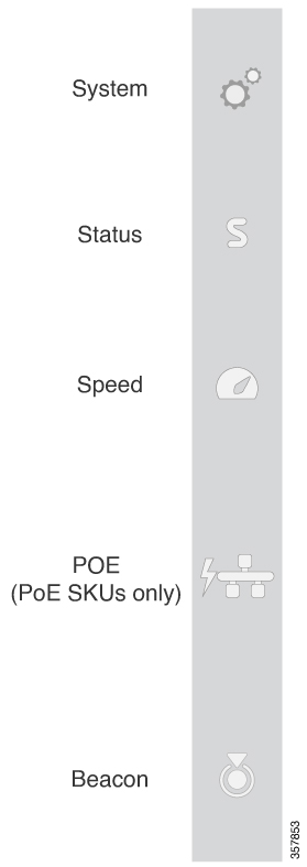
LEDs
Switch Front Panel LEDs
You can use the switch LEDs to monitor switch activity and its performance.

The documentation set for this product strives to use bias-free language. For the purposes of this documentation set, bias-free is defined as language that does not imply discrimination based on age, disability, gender, racial identity, ethnic identity, sexual orientation, socioeconomic status, and intersectionality. Exceptions may be present in the documentation due to language that is hardcoded in the user interfaces of the product software, language used based on RFP documentation, or language that is used by a referenced third-party product. Learn more about how Cisco is using Inclusive Language.
You can use the switch LEDs to monitor switch activity and its performance.

|
Color |
System Status |
|---|---|
|
Off |
System is not powered on. |
|
Green |
System is operating normally. |
|
Blinking green |
System is loading the software. |
|
Amber |
System is receiving power but is not functioning properly. |
|
Color |
System Status |
|---|---|
|
Off |
Status mode is disabled. |
|
Green |
Status mode is enabled. Port LEDs function as described in Port LEDs and Modes. |
| LED Status | Link Status |
|---|---|
|
Off |
Speed mode is disabled. |
|
Green |
Speed mode is enabled. Port LEDs function as described in Port LEDs and Modes. |
The PoE LED indicates the status of the PoE mode: either PoE, PoE+ or UPOE.
| Color | Description |
|---|---|
|
Off |
PoE mode is not enabled. None of the 10/100/1000 ports have been denied power or are in a fault condition. |
|
Green |
PoE mode is enabled and Port LEDs function as described in Port LEDs and Modes. |
Each Ethernet port has a port LED. These port LEDs, as a group or individually, display information about the switch and about the individual ports. To select or change a mode, press the Mode button until the desired mode is highlighted. When you change port modes, the meanings of the port LED colors also change.
|
Port Mode |
Ports |
LED Status |
Link Status |
|---|---|---|---|
|
STAT (port status) |
Off |
No link, or port was administratively shut down. |
|
|
Green |
Link present, no activity. |
||
|
Blinking green |
Activity. Port is sending or receiving data. |
||
|
Alternating green-amber |
Link fault. Error frames can affect connectivity, and errors such as excessive collisions, CRC errors, and alignment and jabber errors are monitored for a link-fault indication. |
||
|
Amber |
Port is blocked by Spanning Tree Protocol (STP) and is not forwarding data. After a port is reconfigured, the port LED can be amber for up to 30 seconds as STP checks the switch for possible loops. |
||
|
Blinking amber |
Port is blocked by STP and is sending and receiving data. |
||
| SPEED |
10/100/1000 ports |
Off |
Port is operating at 10 Mb/s. |
|
Green |
Port is operating at 100 Mb/s. |
||
|
Blinking green (on for 100 ms, off for 1900 ms) |
Port is operating at 1000 Mb/s. |
||
|
Uplink ports with 1G SFP module installed |
Off |
Port is operating at 10 Mb/s. |
|
|
Green |
Port is operating at 100 Mb/s. |
||
|
Blinking green |
Port is operating at 1000 Mb/s. |
||
|
Uplink ports with 10G SFP+ module installed |
Off |
Port is not operating |
|
|
Green |
Port is operating at 10 Gb/s. |
||
|
Blinking green |
Port is operating at 1 Gb/s. |
||
|
PoE+1 |
Off |
PoE mode is not enabled. None of the 10/100/1000 ports have been denied power or are in a fault condition. |
|
|
Green |
PoE mode is enabled, and the port LED displays green when the switch port is providing power. |
||
|
Amber |
PoE is disabled for the port. |
||
|
Blinking amber |
PoE mode is off due to a fault condition. |
||
|
Alternating green and amber |
PoE port is denied power because providing power to the powered device exceeds the switch power capacity. |
||
The PD Power LED indicates the status of the additional LED under the PD port of C9200CX-12T.

| Color | Description | ||
|---|---|---|---|
|
Off |
PD power is not active. |
||
|
Green |
System is powered by PD power. |
||
|
Amber |
System has detected and classified PD power that is insufficient to power the system.
|
The beacon can be enabled by using the CLI.