Information About SCADA

This section contains the following topics:.

Supervisory Control And Data Acquisition (SCADA) Overview

SCADA refers to a control and management system employed in industries such as water management, electric power, and manufacturing. A SCADA system collects data from various types of equipment within the system and forwards that information back to a Control Center for analysis. Generally, individuals located at the Control Center monitor the activity on the SCADA system and intervene when necessary.

The Remote Terminal Unit (RTU) acts as the primary control system within a SCADA system. RTUs are configured to control specific functions within the SCADA system, which can be modified as necessary through a user interface.

On the IR1800, line is 0/2/0 or 0/2/1, same as the Async interface.

Role of the IR1800

In the network, the Control Center always serves as the master in the network when communicating with the IR1800. The IR1800 serves as a proxy master station for the Control Center when it communicates with the RTU.

The IR1800 provides protocol translation to serve as a SCADA gateway to do the following:

  • Receive data from RTUs and relay configuration commands from the Control Center to RTUs.

  • Receive configuration commands from the Control Center and relay RTU data to the Control Center

  • Terminate incoming requests from the Control Center, when an RTU is offline

The IR1800 performs Protocol Translation for the following protocols:

  • IEC 60870 T101 to/from IEC 60870 T104.

  • DNP3 serial to DNP3 IP

Key Terms

The following terms are relevant when you configure the T101 and T104 protocol stacks on the IR1800:

  • Channel–A channel is configured on each IR1800 serial port interface to provide a connection to a single RTU for each IP connection to a remote Control Center. Each connection transports a single T101 (RTU) or T104 (Control Center) protocol stack.

  • Link Address–Refers to the device or station address.

  • Link Mode (Balanced and Unbalanced)–Refers to the modes of data transfer.

    • An Unbalanced setting refers to a data transfer initiated from the master.

    • A Balanced setting can refer to either a master or slave initiated data transfer.

  • Sector–Refers to a single RTU within a remote site.

  • Sessions–Represents a single connection to a remote site.

The following terms are relevant when you configure the DNP3 protocol stacks on the on the IR1800:

  • Channel–A channel is configured on the IR1800 serial port interface to provide a connection to a single RTU for each IP connection to a remote Control Center. Each connection transports a single DNP3 serial (RTU) or DNP3 IP (Control Center) protocol stack.

  • Link Address–Refers to the device or station address.

  • Sessions–Represents a single connection to a remote site.

Protocol Translation Application

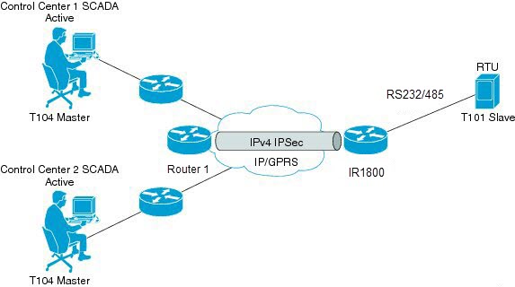
In Routers Within a SCADA System the IR1800 (installed within a secondary substation of the Utility Network) employs Protocol Translation to provide secure, end-to-end connectivity between Control Centers and RTUs within a SCADA System.

The IR1800 connects to the RTU (subordinate) through a RS232/RS485 connection. To protect the traffic when forwarded over public infrastructures (for example, cellular), the IR1800 forwards SCADA data from the RTU to the Control Center in the SCADA system through an IPSec tunnel (FlexVPN site-to-site or hub and spoke). The IPSec tunnel protects all traffic between the IR1800 and the Head-end aggregation router. SCADA traffic can be inspected through an IPS device positioned in the path of the SCADA traffic before it is forwarded to the proper Control Center.

Figure 1. Routers Within a SCADA System

Prerequisites

RTUs must be configured and operating in the network.

For each RTU that connects to the IR1800, you will need the following information for T101/T104:

  • Channel information

    • Channel name

    • Connection type: serial

    • Link transmission procedure setting: unbalanced or balanced

    • Address field of the link (number expressed in octets)

  • Session information

    • Session name

    • Size of common address of Application Service Data Unit (ASDU) (number expressed in octets)

    • Cause of transmission (COT) size (number expressed in octets)

    • Information object address (IOA) size (number expressed in octets)

  • Sector information

    • Sector name

    • ASDU address, (number expressed in octets)

For each RTU that connects to the IR1800, you will need the following information for DNP3:

  • Channel information

    • Channel name

    • Connection type: serial

    • Link address

  • Session information

    • Session name

Guidelines and Limitations

Each channel supports only one session.

Each session supports only one sector.

Default Settings

T101/T104 Parameters

Default

Role for T101

Master

Role for T104

Slave

DNP3 Parameters

Default

Unsolicited Response (DNP3-serial)

Not Enabled

Send Unsolicited Message (DNP3-IP)

Enabled

Configuring Protocol Translation

This section includes the following topics:


Note


Before making any configuration changes to a IR1800 operating with Protocol Translation, please review the section on Starting and Stopping the Protocol Translation Engine.

Enabling the IR1800 Serial Port and SCADA Encapsulation

Before you can enable and configure Protocol Translation on the IR1800, you must first enable the serial port on the IR1800 and enable SCADA encapsulation on that port.

Before you begin

Determine the availability of a serial port on the IR1800.

Procedure

  Command or Action Purpose

Step 1

configure terminal

Enters the global configuration mode.

Step 2

interface async slot/port/interface

Enters the interface command mode for the async slot/port/interface.

slot –value of 0

port –value of 2

interface –value of 0 or 1

Step 3

no shutdown

Brings up the port, administratively.

Step 4

encapsulation scada

Enables encapsulation on the serial port for protocol translation and other SCADA protocols.

Enable Serial Port Example

This example shows how to enable serial port 0/2/0 and how to enable encapsulation on that interface to support SCADA protocols.


router# configure terminal 
router(config)# interface async 0/2/0
router (config-if)# no shutdown
router (config-if)# encapsulation scada

Configuring T101 and T104 Protocol Stacks

You can configure T101 and T104 protocol stacks, which allow end-to-end communication between Control Centers (T104) and RTUs (T101) within a SCADA system.

Protocol Stack Prerequisites

Ensure that you have gathered all the required configuration information.

Enable the serial port and SCADA encapsulation.

Configuring the T101 Protocol Stack

Configure the channel, session, and sector parameters for the T101 protocol stack.

Procedure

  Command or Action Purpose

Step 1

configure terminal

Enters global configuration mode.

Step 2

scada-gw protocol t101

Enters the configuration mode for the T101 protocol.

Step 3

channel channel_name

Enters the channel configuration mode for the T101 protocol.

channel_name –Identifies the channel on which the serial port of the IR1800 communicates to the RTU.

Note

 
When the entered channel name does not already exist, the router creates a new channel.

Entering the no form of this command deletes an existing channel. However, all sessions must be deleted before you can delete a channel.

Step 4

role master

Assigns the master role to the T101 protocol channel (default).

Step 5

link-mode {balanced | unbalanced}

Configures the link-mode as either balanced or unbalanced.

unbalanced–Refers to a data transfer initiated from the master.

balanced–Refers to either a master or slave data transfer.

Step 6

link-addr-size {none | one | two}

Defines the link address size in octets.

Step 7

bind-to-interface async slot/port/interface

Defines the IR1800 serial interface on which the system sends its T101 protocol traffic.

slot –Value of 0

port –Value of 2

interface –Value of 0 or 1

Step 8

exit

Ends configuration of the channel and exits the channel configuration mode. Saves all settings.

Step 9

session session_name

Enters the session configuration mode and assigns a name to the session.

Step 10

attach-to-channel channel_name

Attaches the session to the channel.

Enter the same channel name that you entered in Step 3 .

channel_name –Identifies the channel.

Step 11

common-addr-size {one | two | three}

Defines the common address size in octets.

Step 12

cot size {one | two | three}

Defines the cause of transmission such as spontaneous or cyclic data schemes in octets.

Step 13

info-obj-addr-size {one | two | three}

Defines the information object element address size in octets.

Step 14

link-addr-size {one | two | three}

Defines the link address size in octets.

Step 15

link-addr link_address

Refers to the link address of the RTU.

Note

 
The link address entered here must match the value set on the RTU to which the serial port connects.

link_address –Range of 0-65535.

Step 16

exit

Exits the session configuration mode.

Step 17

sector sector_name

Enters the sector configuration mode and assigns a name to the sector for the RTU.

sector_name –Identifies the sector.

Step 18

attach-to-session session_name

Attaches the RTU sector to the session.

Enter the same session name that you entered in Step 9 .

session_name- Identifies the session.

Step 19

asdu-addr asdu_address

Refers to the ASDU structure address of the RTU.

Step 20

exit

Exits the sector configuration mode.

Step 21

exit

Exits the protocol configuration mode.

T101 Protocol Stack Example

This example shows how to configure the parameters for the T101 protocol stack for RTU_10 .

router# configure terminal 
router(config)# scada-gw protocol t101
router(config-t101)# channel rtu_channel
router(config-t101-channel)# role master
router(config-t101-channel)# link-mode unbalanced
router(config-t101-channel)# link-addr-size
 one
router(config-t101-channel)# bind-to-interface async 0/2/0
router(config-t101-channel)# exit
router(config-t101)# session rtu_session
router(config-t101-session)# attach-to-channel rtu_channel
router(config-t101-session)# common-addr-size two
router(config-t101-session)# cot-size one
router(config-t101-session)# info-obj-addr-size two
router(config-t101-session)# link-addr 3
router(config-t101-session)# exit
router(config-t101)# sector rtu_sector
router(config-t101-sector)# attach-to-session rtu_session
router(config-t101-sector)# asdu-addr 3
router(config-t101-sector)# exit
router(config-t101)# exit
router(config)#

T101 Configuration Example

The following example shows how to configure the serial port interface for T101 connection, configure T101 and T104 protocol stacks, and starts the Protocol Translation Engine on the IR1800.

router# configure terminal 
router(config)# interface async 0/2/0
router (config-if)# no shutdown
router (config-if)# encapsulation scada
router (config-if)# exit
router(config)# scada-gw protocol t101
router(config-t101)# channel rtu_channel
router(config-t101-channel)# role master
router(config-t101-channel)# link-mode unbalanced
router(config-t101-channel)# link-addr-size one
router(config-t101-channel)# bind-to-interface async 0/2/0
router(config-t101-channel)# exit
router(config-t101)# session rtu_session
router(config-t101-session)# attach-to-channel rtu_channel
router(config-t101-session)# common-addr-size two
router(config-t101-session)# cot-size one
router(config-t101-session)# info-obj-addr-size two
router(config-t101-session)# link-addr 3
router(config-t101-session)# exit
router(config-t101)# sector rtu_sector
router(config-t101-sector)# attach-to-session rtu_session
router(config-t101-sector)# asdu-addr 3
router(config-t101-sector)# exit
router(config-t101)# exit
router(config)# scada-gw protocol t104
router(config-t104)# channel cc_master1
router(config-t104-channel)# k-value 12
router(config-t104-channel)# w-value 8
router(config-t104-channel)# t0-timeout 30
router(config-t104-channel)# t1-timeout 15
router(config-t104-channel)# t2-timeout 10
router(config-t104-channel)# t3-timeout 30
router(config-t104-channel)# tcp-connection 0 local-port 2050 remote-ip any
router(config-t104-channel)# tcp-connection 1 local-port 2051 remote-ip any
router(config-t104-channel)# exit
router(config-t104)# session cc_master1
router(config-t104-session)# attach-to-channel cc_master1
router(config-t104-session)# cot-size two
router(config-t104-session)# exit
router(config-t104)# sector cc_master1-sector
router(config-t104-sector)# attach-to-session cc_master1
router(config-t104-sector)# asdu-adr 3
router(config-t104-sector)# map-to-sector rtu_sector
router(config-t104)# exit
router(config-t104)# session cc_master2
router(config-t104-session)# attach-to-channel cc_master2
router(config-t104-session)# cot-size two
router(config-t104-session)# exit
router(config-t104)# sector cc_master2-sector
router(config-t104-sector)# attach-to-session cc_master2
router(config-t104-sector)# asdu-adr 3
router(config-t104-sector)# map-to-sector rtu_sector
router(config-t104-sector)# exit
router(config-t104)# exit
router(config)# scada-gw enable

This example configures end-to-end communication between Control Centers and RTUs within a SCADA system using the DNP3 protocol stacks and starts the Protocol Translation Engine on the IR1800:

router# configure terminal 
router(config)# interface async 0/2/0
router (config-if)# no shutdown
router (config-if)# encapsulation scada
router (config-if)# exit
router(config)# scada-gw protocol dnp3-serial
router(config-dnp3s)# channel rtu_channel
router(config-dnp3s-channel)# bind-to-interface async 0/2/0
router(config-dnp3s-channel)# link-addr source 3
router(config-dnp3s-channel)# unsolicited-response enable
router(config-dnp3s-channel)# exit
router(config-dnp3s)# session rtu_session
router(config-dnp3s-session)# attach-to-channel rtu_channel
router(config-dnp3s-session)# link-addr dest 3
router(config-dnp3s-session)# exit
router(config-dnp3s)# exit
router(config)# scada-gw protocol dnp3-ip
router(config-dnp3n)# channel cc_channel
router(config-dnp3n-channel)# link-addr dest 3
router(config-dnp3n-channel)# tcp-connection local-port default remote-ip any
router(config-dnp3n-channel)# exit
router(config-dnp3n)# session cc_session
router(config-dnp3n-session)# attach-to-channel cc_channel
router(config-dnp3n-session)# link-addr source 3
router(config-dnp3n-session)# map-to-session rtu_session
router(config-dnp3n)# exit
router(config)# exit
router(config)# scada-gw enable

Configuring the T104 Protocol Stack

Follow the steps below for each Control Center that you want to connect to over a T104 protocol.

Before you begin

Ensure that you have gathered all the required configuration information. (See Prerequisites)

Enable the serial port and SCADA encapsulation. (See Enabling the IR1800 Serial Port and SCADA Encapsulation)

Procedure

  Command or Action Purpose

Step 1

configure terminal

Enters configuration mode.

Step 2

scada-gw protocol t104

Enters the configuration mode for the T104 protocol.

Step 3

channel channel_name

Enters the channel configuration mode for the T104 protocol.

channel_name –Identifies the channel on which the router communicates with the Control Center.

Note

 
When the entered channel name does not already exist, the router creates a new channel.

Entering the no form of this command deletes an existing channel. However, all sessions must be deleted before you can delete a channel.

Step 4

k-value value

Sets the maximum number of outstanding Application Protocol Data Units (APDUs) for the channel.

Note

 
An APDU incorporates the ASDU and a control header.

value –Range of values from 1 to 32767. Default value is 12 APDUs.

Step 5

w-value value

Sets the maximum number of APDUs for the channel.

value –Range of values from 1 to 32767. Default value is 8 APDUs.

Step 6

t0-timeout value

Defines the t0-timeout value for connection establishment of the T104 channel.

Step 7

t1-timeout value

Defines the t1-timeout value for send or test APDUs on the T104 channel.

Step 8

t2-timeout value

Defines the t2-timeout value for acknowledgements when the router receives no data message.

Note

 
The t2 value must always be set to a lower value than the t1 value on the T104 channel.

Step 9

t3-timeout value

Defines the t3-timeout value for sending s-frames in case of a long idle state on the T104 channel.

Note

 
The t3 value must always be set to a higher value than the t1 value on the T104 channel.

Step 10

tcp-connection {0|1} local-port {port_number | default} remote-ip {A.B.C.D | A.B.C.D/LEN | any} [vrf WORD]

In a configuration where there are redundant Control Centers, sets the connection value for the secondary Control Center as defined on the primary Control Center.

port-number –value between 2000 and 65535.

default–value of 2404.

A.B.C.D –single host.

A.B.C.D/nn –subnet A.B.C.D/LEN.

any–any remote hosts 0.0.0.0/0.

WORD–VRF name.

Step 11

exit

Exits the channel configuration mode.

Step 12

session session_name

Enters the session configuration mode and assigns a name to the session.

session_name –Use the same name that you assigned to the channel in Step 3 .

Step 13

attach-to-channel channel_name

Defines the name of the channel that transports the session traffic.

Step 14

cot size {one | two | three}

Defines the cause of transmission (cot), such as spontaneous or cyclic data schemes in octets.

Step 15

exit

Exits the session configuration mode.

Step 16

sector sector_name

Enters the sector configuration mode and assigns a name to the sector for the Control Center.

Step 17

attach-to-session session_name

Attaches the Control Center sector to the channel.

session_name –Use the same name that you assigned to the channel in Step 3 .

Step 18

asdu-addr asdu_address

Refers to the ASDU structure address. Value entered here must match the ASDU value on the RTU.

asdu_addressasdu_address –Value of 1 or 2.

Step 19

map-to-sector sector_name

Maps the Control Center (T104) sector to the RTU (T101) sector.

Step 20

Return to Step 1 .

Repeat all steps in this section for each Control Center active in the network.

Configure T104 Protocol Stack Example

This example shows how to configure the parameters for the T104 protocol stack on Control Center 1 and Control Center 2, both of which are configured as masters , and how to map the T104 sector to the T101 sector.

To configure Control Center 1 (cc_master1 ), enter the following commands.

router# configure terminal 
router(config)# scada-gw protocol t104
router(config-t104)# channel cc_master1
router(config-t104-channel)# k-value 12
router(config-t104-channel)# w-value 8
router(config-t104-channel)# t0-timeout 30
router(config-t104-channel)# t1-timeout 15
router(config-t104-channel)# t2-timeout 10
router(config-t104-channel)# t3-timeout 30
router(config-t104-channel)# tcp-connection 0 local-port 2050 remote-ip 209.165.200.225
router(config-t104-channel)# tcp-connection 1 local-port 2051 remote-ip 209.165.201.25
router(config-t104-channel)# exit
router(config-t104)# session
 cc_master1
router(config-t104-session)# attach-to-channel cc_master1
router(config-t104-session)# cot-size two
router(config-t104-session)# exit
router(config-t104)# sector cc_master1-sector
router(config-t104-sector)# attach-to-session cc_master1
router(config-t104-sector)# asdu-adr 3
router(config-t104-sector)# map-to-sector rtu_sector
router(config-t104)# exit
router(config)#

To configure Control Center 2 (cc_master2 ), enter the following commands.

router(config)# scada-gw protocol t104
router(config-t104)# channel cc_master2
router(config-t104-channel)# k-value 12
router(config-t104-channel)# w-value 8
router(config-t104-channel)# t0-timeout 30
router(config-t104-channel)# t1-timeout 15
router(config-t104-channel)# t2-timeout 10
router(config-t104-channel)# t3-timeout 30
router(config-t104-channel)# tcp-connection 0 local-port 2060 remote-ip 209.165.201.237
router(config-t104-channel)# tcp-connection 1 local-port 2061 remote-ip 209.165.200.27
router(config-t104-channel)# exit
router(config-t104)# session cc_master2
router(config-t104-session)# attach-to-channel cc_master2
router(config-t104-session)# cot-size two
router(config-t104-session)# exit
router(config-t104)# sector cc_master2-sector
router(config-t104-sector)# attach-to-session cc_master2
router(config-t104-sector)# asdu-adr 3
router(config-t104-sector)# map-to-sector rtu_sector
router(config-t104-sector)# exit
router(config-t104)# exit
router(config)# 

Configuring the DNP3 Protocol Stacks

You can configure the DNP3 serial and DNP3 IP protocol stacks, which allow end-to-end communication between Control Centers and RTUs within a SCADA system.

Configuring DNP3 Serial

Configure the channel and session parameters for the DNP serial communication with an RTU.

Procedure

  Command or Action Purpose

Step 1

configure terminal

Enters global configuration mode.

Step 2

scada-gw protocol dnp3-serial

Enters configuration mode for the DNP3 serial protocol.

Step 3

channel channel_name

Enters channel configuration mode for the DNP3 serial protocol.

channel_name –Identifies the channel on which the router serial port communicates to the RTU.

Note

 
When the entered channel name does not already exist, the router creates a new channel

Entering the no form of this command deletes an existing channel. However, all sessions must be deleted before you can delete a channel.

Step 4

bind-to-interface async0/2/0

Defines the router async interface on which the system sends its DNP3 protocol traffic.

Step 5

link-addr source source_address

Refers to the link address of the master.

source_address –Range of values from 1 to 65535.

Step 6

unsolicited-response enable

(Optional) Allows unsolicited responses.

Entering the no form of this command disables unsolicited responses.

The default is disabled.

Step 7

exit

Ends configuration of the channel and exits channel configuration mode. Saves all settings.

Step 8

session session_name

Enters session configuration mode and assigns a name to the session.

Note

 
When the entered session name does not already exist, the router creates a new session.

Entering the no form of this command deletes an existing session.

Step 9

attach-to-channel channel_name

Attaches the session to the channel.

Note

 
Enter the same channel name that you entered in Step 3 above.

channel_name –Identifies the channel.

Step 10

link-addr dest destination_address

Refers to the link address of the slave.

destination_address –Range of values from 1 to 65535.

Step 11

exit

Exits session configuration mode.

Step 12

exit

Exits protocol configuration mode.

DPN3-Serial Protocol Stack Example

This example shows how to configure the parameters for the DPN3-serial protocol stack:

router# configure terminal 
router(config)# scada-gw protocol dnp3-serial
router(config-dnp3s)# channel rtu_channel
router(config-dnp3s-channel)# bind-to-interface async 0/2/0
router(config-dnp3s-channel)# link-addr source 3
router(config-dnp3s-channel)# unsolicited-response enable
router(config-dnp3s-channel)# exit
router(config-dnp3s)# session rtu_session
router(config-dnp3s-session)# attach-to-channel rtu_channel
router(config-dnp3s-session)# link-addr dest 3
router(config-dnp3s-session)# exit
router(config-dnp3s)# exit
router(config)#

Configuring DNP3 IP

Follow the steps below for the Control Center that you want to connect to over DNP3 IP. For redundancy, you can create multiple connections that share the same session configuration under the same session.

Procedure

  Command or Action Purpose

Step 1

configure terminal

Enters configuration mode.

Step 2

scada-gw protocol dnp3-ip

Enters configuration mode for the DNP-IP protocol.

Step 3

channel channel_name

Enters channel configuration mode for the DNP-IP protocol.

channel_name –Identifies the channel on which the router communicates with the Control Center.

Note

 
When the entered channel name does not already exist, the router creates a new channel.

Entering the no form of this command deletes an existing channel. However, all sessions must be deleted before you can delete a channel.

Step 4

link-addr dest destination_address

Refers to the link address of the master.

destination_address –Range of values from 1 to 65535.

Step 5

send-unsolicited-msg enable

(Optional) Allow unsolicited messages.

The default is enabled.

Step 6

tcp-connection local-port [default | local_port ] remote-ip [any | remote_ip | remote_subnet ]

Configures the local port number and remote IP address for the TCP connection:

  • default

    –20000.
  • local_port –Range of values from 2000 to 65535.

  • any–Any remote hosts 0.0.0.0/0

  • remote_ip –Single host: A.B.C.D

  • remote_subnet –Subnet: A.B.C.D/LEN

If remote_subnet is specified, when two channels have the same local ports, the remote subnets cannot overlap each other.

Note

 
Every <local-port, remote-ip> must be unique per channel. If remote_subnet is specified, when two channels have the same local ports, the remote subnets cannot overlap each other.

Step 7

exit

Exits channel configuration mode.

Step 8

session session_name

Enters session configuration mode and assigns a name to the session.

Note

 
When the entered session name does not already exist, the router creates a new session.

Entering the no form of this command deletes an existing session.

Step 9

attach-to-channel channel_name

Attaches the session to the channel.

Enter the same channel name that you entered in Step 3.

channel_name –Identifies the channel.

Step 10

link-addr source source_address

Refers to the link address of the slave.

source_address –Value of 1-65535.

Step 11

map-to-session session_name

Maps the dnp3-ip session to an existing dnp3-serial session.

Note

 
One dnp3-ip session can be mapped to only one dnp3-serial session.

Step 12

exit

Exits session configuration mode.

Step 13

exit

Exits protocol configuration mode.

DNP3 IP Parameters Example

This example shows how to configure the DNP3 IP parameters:

router# configure terminal 
router(config)# scada-gw protocol dnp3-ip
router(config-dnp3n)# channel cc_channel
router(config-dnp3n-channel)# link-addr dest 3
router(config-dnp3n-channel)# tcp-connection local-port default remote-ip any
router(config-dnp3n-channel)# exit
router(config-dnp3n)# session cc_session
router(config-dnp3n-session)# attach-to-channel cc_channel
router(config-dnp3n-session)# link-addr source 4
router(config-dnp3n-session)# map-to-session rtu_session
router(config-dnp3n)# exit
router(config)# exit

Starting and Stopping the Protocol Translation Engine

Before starting the Protocol Translation Engine on the router for the first time, make sure you complete the following items:

Enabling the IR1800 Serial Port and SCADA Encapsulation

Configuring T101 and T104 Protocol Stacks

You must start the Protocol Translation Engine to use Protocol Translation on the IR1800.

Starting – After enabling SCADA encapsulation on the IR1800 serial port and configuring the T101 and T104 protocols on the IR1800, you can start the Protocol Translation Engine.

Stopping – Before you can make any configuration changes to Protocol Translation on the IR1800 with an active Protocol Translation Engine, you must stop the engine.

Procedure

  Command or Action Purpose

Step 1

configure terminal

Enters global configuration mode.

Step 2

scada-gw enable

Starts (scada-gw enable ) or stops (no scada-gw enable ) the Protocol Translation Engine on the IR1800.

Start Protocol Translation Engine Example

To start the protocol translation engine on the router, enter the following commands:

router# configure terminal
router(config)# scada-gw enable

To stop the protocol translation engine on the router, enter the following commands:

router# configure terminal
router(config)# no
 scada-gw enable

SCADA Enhancement for TNB

This enhancement provides compatibility with TNB’s WG RTUs, including the following:

  • TNB RTUs require Reset-Link message to be sent out along with Link-Status message to ensure correct initialization of the serial. The feature can be selectively turned on using the new configuration CLI scada-gw protocol force reset-link.

  • When clock passthru is enabled and if the router hasn’t received the timestamp from the DNP3-IP master, the router’s hardware time will be sent downstream to RTU. Upon receiving a new timestamp from DNP3-IP master, the router will start sending the new timestamp sourced from DNP3-IP master to RTU.

  • The number of bufferable DNP3 events in memory will be increased from 600 to 10000.

  • The scada-gw protocol interlock command will be supported for DNP3. Previously, the support only existed for T101/T104. With this new enhancement, the router will disconnect Serial link if the DNP3-IP master is down or unreachable. Similarly, when the Serial link to RTU is down, the TCP connection to DNP3-IP master will be untethered.

  • Custom “requests” will be automatically ordered based on priority so that the user can specify them in any order that they would like to.

Verifying Configuration

Command

Purpose

show running-config

Shows the configuration of the router including active features and their settings.

show scada database

Displays details on the SCADA database.

show scada statistics

Shows statistics for the SCADA gateway, including the number of messages sent and received, timeouts, and errors.

show scada tcp

Displays TCP connections associated with the SCADA gateway.

This example shows the output from the show scada tcp and show scada statistics commands:

router# show scada tcp
DNP3 network channel [test]: 4 max simultaneous connections
conn: local-ip: 3.3.3.21        local-port 20000        remote-ip 3.3.3.15      data-socket 1
Total:
  1 current client connections
  0 total closed connections
router# show scada statistics 
DNP3 network Channel [test]:
  5 messages sent, 2 messages received
  0 timeouts, 0 aborts, 0 rejections
  2 protocol errors, 2 link errors, 0 address errors
DNP3 serial Channel [test]:
  152 messages sent, 152 messages received
  1 timeouts, 0 aborts, 0 rejections
  0 protocol errors, 0 link errors, 0 address errors

SCADA Debug Commands

This section lists some debug commands that are helpful when troubleshooting.

Table 1. SCADA Function Level Debug Commands

Command

Purpose

debug scada function config

Configuration trace

debug scada function control

Control trace

debug scada function file

File trace

debug scada function freeze

Freeze trace

debug scada function physical

Physical trace

debug scada function poll

Poll trace

debug scada function stack

Stack trace

debug scada function umode

Umode trace