Digital I/O, Ignition, and CAN Bus Connectivity

This section contains the following:

Overview

This section covers the Digital I/O configuration and the CAN Bus details.

The IR1835 supports four General-Purpose Input/Output ports (GPIO), also referred to as digital I/O ports. A GPIO port can be configured as input OR output alarm. It can work as dry or wet contact, protected up to +60V .

The Controller Area Network (CAN) Bus enables the ECU (electronic control unit) in a vehicle to communicate with all other ECUs. It consists of two wires, CAN bus High and Low supporting data rate up to 1 Mbs.

The characteristics of the high speed CAN Bus 2.0B are ISO 11898-1 data link layer, ISO 11898-2 and ISO-11898-5 physical layer up to 1Mbs data rate (SW dependent).

Digital IO

A total of four Digital IO with a common return are supported. Digital IO is similar to the ALARM IN and ALARM OUT supported in the IE switches and IR routers. The differences are the ALARM IN is a dedicated input, the ALARM OUT is a dedicated output whereas the Digital IO can be input or output. ALARM OUT includes a relay to provide the Normally Open (NO) or Normally Close (NC) terminals. Digital IO implements a relay feature similar to Alarm port.

The following configuration commands are available:


alarm contact attach-to-iox
alarm contact <1-4> enable enable
alarm contact <1-4> application 
alarm contact <1-4> description 
alarm contact <1-4> severity 
alarm contact <1-4> threshold <1600-2700>
alarm contact <1-4> trigger 
alarm contact <1-4> output <1 | 0>
alarm contact <1-4> output relay temperature
alarm contact <1-4> output relay input-alarm <0-4>

All configuration commands also come with a no prefix to them.

Controller Area Network (CAN) Bus

Details on the CAN Bus and connectivity to the vehicle's On-Board Diagnostic (OBD-II) are covered in the Cisco Catalyst IR1800 Rugged Series Router Hardware Installation Guide.

The CAN Bus interface can be viewed using the command line interface. Some of the CLIs are:
IR1800#conf term
Enter configuration commands, one per line.  End with CNTL/Z.
IR1800(config)#canbus baudrate ?
  <125000-1000000>  enter baud rate ranging from 125000 to 1000000

IR1800#show platform hardware canbus ?
  interface  Display CAN Bus interface
  link       Display CAN Bus link

IR1800#show platform hardware canbus link
8: can0: <NOARP,UP,LOWER_UP,ECHO> mtu 16 qdisc pfifo_fast state UP mode DEFAULT group default qlen 10
    link/can  promiscuity 0 
    can state ERROR-ACTIVE restart-ms 100 
          bitrate 125000 sample-point 0.875 
          tq 500 prop-seg 6 phase-seg1 7 phase-seg2 2 sjw 1
          mcp251x: tseg1 3..16 tseg2 2..8 sjw 1..4 brp 1..64 brp-inc 1
          clock 10000000
          re-started bus-errors arbit-lost error-warn error-pass bus-off
          0          0          0          0          0          0         

numtxqueues 1 numrxqueues 1 gso_max_size 65536 gso_max_segs 65535 

    RX: bytes  packets  errors  dropped overrun mcast   
    0          0        0       0       0       0       
    TX: bytes  packets  errors  dropped carrier collsns 
    0          0        0       0       0       0       

IR1800#
IR1800#show platform hardware canbus interface 
can0      Link encap:UNSPEC  HWaddr 00-00-00-00-00-00-00-00-00-00-00-00-00-00-00-00  
          UP RUNNING NOARP  MTU:16  Metric:1
          RX packets:0 errors:0 dropped:0 overruns:0 frame:0
          TX packets:0 errors:0 dropped:0 overruns:0 carrier:0
          collisions:0 txqueuelen:10 
          RX bytes:0 (0.0 B)  TX bytes:0 (0.0 B)

IOx CAN Bus Support

A vxcan tunnel is created between Linux and IOx, and then the CAN_GW inside the linux is configured to forward CANBus traffic from/to the real can bus interface (i.e. can0) to/from the end point of the vxcan tunnel.

A vxcan tunnel is established by default, the CANBus traffic will be sent over the tunnel as follows:

CANBus: [Linux] vxcan-ap and vxcan0 [IOx]

Sample output from vxcan0 [IOx]


vxcan0    Link encap:UNSPEC  HWaddr 00-00-00-00-00-00-00-00-00-00-00-00-00-00-00-00  
          UP RUNNING NOARP  MTU:16  Metric:1
          RX packets:715 errors:0 dropped:0 overruns:0 frame:0
          TX packets:530 errors:0 dropped:0 overruns:0 carrier:0

Important Notes

  • The feature can support multiple containers, one pair of vxcan will be setup for one container, therefore, two pairs of vxcan will be setup for two containers.

  • Within one container, if multiple applications need to access vxcan, it is customer's application responsibility to include CAN_GW in their software.

Packet Capture Support for CANBUS

When enabled, this feature will capture packets sent and received on the IR1800 series CANBUS. Once captured, the data will be exported as a packet capture (PCAP) file to allow for further examination. The feature is configured in exec mode and is only temporary, meaning it is not permanent across a reboot/reload.

A file name is required for the capture. The default location for the capture file is at bootflash:/canbus_dumplogs. If the capture is started without specifying the file initially, or after the router is reloaded, you will get the following message when you check the status:

canbus packetdump file pcapfile path bootflash:/canbus_dumplogs/pcapfile didn't start

After stopping the capture, if you want to start the capture again without specifying the file name, the old specified name will be overwritten.

Use the following command to specify the name of the capture file:

Router#monitor canbus packetdump file <filename>

Note


You do not need to specify the path, the only supported path is the default path bootflash:/canbus_dumplogs

Use the following command to start the capture using the specified <filename> from the command above:

Router#monitor canbus packetdump start

Use the following command to stop the capture:

Router#monitor canbus packetdump stop

Use the following command to check the status of the monitoring:

Router#show canbus packetdump

Command Examples

Router#monitor canbus packetdump ?
file CAN Bus interface packet capture destination file
start CAN Bus interface packet capture start
stop CAN Bus interface packet capture stop

Router#monitor canbus packetdump file canbusfile
Router#show canbus packetdump
canbus packetdump file canbusfile path bootflash:/canbus_dumplogs/canbusfile didn't start

Router#monitor canbus packetdump start
Router#show canbus packetdump
canbus packetdump file canbusfile path bootflash:/canbus_dumplogs/canbusfile started

Router#monitor canbus packetdump stop
Router#show canbus packetdump
canbus packetdump file canbusfile path bootflash:/canbus_dumplogs/canbusfile didn't start
Configuring Digital IO

To configure the feature, perform the following:


Router(config)# alarm contact 2 enable
Router(config)#default alarm contact 2 output
Router(config)#default alarm contact 2 severity
Router(config)#default alarm contact 2 threshold
Router(config)#default alarm contact 2 trigger
Router(config)#default alarm contact 2 application
Router(config)#default alarm contact 2 description
Router(config)#end

To view alarm output, perform the following:


Router# show alarm | section Digital I/O 2
Digital I/O 2:
Description: External digital I/O port 2
Status: Not Asserted
Application: Dry
Severity: minor
Trigger: Closed
Voltage: 3300mV
Threshold: 1600mV
Mode: Input
Router#

Ignition Power Management Overview

This section provides a description and instructions for configuration of the Ignition Power Management feature of the IR1800 router. Ignition Power Management prevents the router from draining the charge of the battery on automotive applications. It also keeps the router up and running while the vehicle is stopped. Therefore, users do not have to wait for routers to reload each time the vehicle is stopped.

When the engine is running, it generates energy and recharges the battery. When the ignition is turned off, the router can remain operational for a pre-determined period of time.

On the IR1800 series, there are two ways to perform Ignition Power Management. All of the routers in the series can use the software based voltage sense controlled by the MCU. The IR1835 can also use the Signal/Ignition signal, available from the Ignition pin in the GPIO 6 pins connector.

Ignition Wiring information is found in the Hardware Installation Guide.

Features of Ignition Power Management

Ignition Power Management is controlled through the MCU built into the router. The MCU provides auto detection of power input to detect if the ignition is on or off. Ignition on is detected by if the ignition signal is on or off, or by sensing the power input level.

Ignition Power Management Cabling and Connector is covered here: https://www.cisco.com/c/en/us/td/docs/routers/access/IR1800/hig/b-ir1800-hig/m-GPIO.html

The system software tries to prevent the discharge of the battery with the following:

  • Turning the router off if the vehicle has the ignition off for a period of time (programmable).

  • Turning the router off if the battery voltage drops to a certain level (programmable).

  • Attempting to protect the router by turning the router off if the battery voltage rises above a certain level (fixed amount of time).

The system software logs the following events to the system log:

  • When the user turns on or off the ignition management feature with CLI

  • When the ignition is turned on or off

  • When the ignition-off timer expires and the system goes off

  • When the user enables or disables the feature through the CLI

  • Tentatively logs the under-voltage and over-voltage events

All Ignition On, Off, Low and High input thresholds can be stored in non-volatile memory. When the device boots up, the thresholds will be retrieved from the memory to the register. When the CPU detects the front panel push button, the non-volatile memory will reset to default value.

Ignition Sense Overview

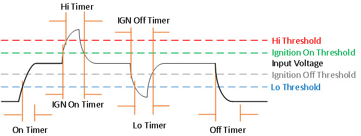
On the IR1800, Ignition Power Management adds ignition sense through software. Ignition sense can be determined by either monitoring the ignition signal pin, or the battery voltage level. The ignition pin and voltage level are continuously monitored. This input will be the main signal to start the state machine. If the ignition signal is not active, then voltage level sense will be used. There is an option for user to disable the voltage level sense by clearing the Ignition Voltage Sense Enable register.

See the following table:

Ignition Bypass

Ignition Voltage Sense Enable

Ignition Sense

0

0

Ignition Signal

0

1

Voltage Level

1

x

Ignition Disabled

The following graphic illustrates Ignition Sense:

Figure 1. Ignition Based on Voltage (Analog Input)

The following tables provide voltage details:

Table 1. Input Voltage (DC)

Minimum

9.6V

Maximum

36V

Nominal

12V or 24V

Table 2. Ignition Sense Voltage

12V Battery

24V Battery

On

13V + 2%

26V + 2%

Off

13V -2%

26V - 2%

Table 3. Battery Voltage

12V Battery

24V Battery

Under-Voltage

11.5V

23V

Over-Voltage

36V

36V

See the following command output example:

IR1800#show run | s ignition
ignition off-timer 300
ignition undervoltage threshold 9 000
ignition battery-type 12v
ignition sense-voltage threshold 13 000
ignition sense
ignition enable

IR1800#show ignition status
Status:
  Ignition management: Enabled
  Input voltage:       11.953 V
  Ignition status:     Timing ignition off shut down
  Ignition Sense:      Enabled
  Shutdown timer:      242.0 s to off [will begin power down at ~100 sec]
  Config-ed battery:   12v
Thresholds:
  Undervoltage:        9.000 V
  Overvoltage:         37.000 V
  Sense on:            13.000 V
  Sense off:           12.800 V
  Undervoltage timer:  20.0 s
  Overvoltage timer:   1.0 s
  Ignition-Off timer:  300.0 s

IR1835 Ignition Switch

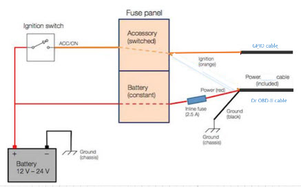
The IR1835 is the only model in the IR1800 series that offers ignition monitoring via the Signal/Ignition signal, available from the Ignition pin in the GPIO 6 pins connector.

Refer to the following figure:

Figure 2. Ignition based on Signal/Ignition switch(Digital Input)

There are two ways to power the router:

  • CANBUS power

  • Through the CAB-PWR-15-MF4 cable

There are two thresholds:

  • 12V — Defaults ignition sense-voltage threshold 13

  • 24V — Defaults ignition sense-voltage threshold 26

See the following command output example:

IR1835#show run | s ignition ! Configuring
ignition off-timer 120
ignition undervoltage threshold 9 600
ignition battery-type 12v
ignition sense-voltage threshold 13 000
no ignition sense
ignition enable

IR1835#show ignition Status ! Monitoring 
 Ignition management: Enabled  
Input voltage:       13.999 V  
Ignition status:     Power on  
Ignition Sense:      Disabled 
 Shutdown timer:      0.0 s to off [will begin power down at ~100 sec]  
Config-ed battery:   12v
Thresholds:  
Undervoltage:        9.600 V  
Overvoltage:         37.000 V  
Sense on:            13.200 V  
Sense off:           12.800 V  
Undervoltage timer:  20.0 s  
Overvoltage timer:   1.0 s  
Ignition-Off timer:  120.0 s

IR1800 Ignition and Battery Voltage

The IR1800 can be set-up with a 12V or 24V battery. The ignition sense voltage level will change accordingly.

  • 12Volt Battery

    • If input voltage > 13.200V for more than 1 second, Ignition is ON

    • If input voltage < 12.800V for more than 20 seconds, Ignition is OFF

  • 24Volt Battery

    • If input voltage > 26.200V for more than 1 second, Ignition is ON

    • If input voltage < 25.800V for more than 20 seconds, Ignition is OFF

Use the folowing command to determine your battery type:

IR1800#conf term
Enter configuration commands, one per line.  End with CNTL/Z.
IR1800(config)#ignition battery-type ?
  12v  The battery is 12v
  24v  The battery is 24v

Command Line Interface (CLI)

The Ignition Power Management feature of the IR1800 series uses a command line interface.

Enabling Ignition Power Management

The feature is disabled by default, and enabled using the following command:
Router(config)#ignition enable
Router(config)#
*Sep 15 16:08:27.697: %IGNITION-5-IGN_ENABLE_CMD: The Ignition Power Management is enabled
Router(config)#end

Options to the ignition enable command are:

Router(config)#ignition enable ?
  enable        Enable ignition power management feature
  off-timer     Off timer delay
  sense         Enable ignition power sense feature
  undervoltage  Set undervoltage parameters for shutting the system off
  • Ignition off timer value. After the ignition is turned off the router will stay operational for this amount of time, then it shuts down if the ignition is still off:

Router#ignition off-timer <value>
  • Ignition sense value. Turning this on allows the router to detect if the the ignition is on or off.

Router(config)#ignition sense 
*Sep 15 16:08:14.391: %IGNITION-5-IGN_SENSE_CMD: The Ignition Voltage Sense is enabled
Router(config)#end
  • Ignition undervoltage. This command allows you to set parameters for shutting down the router.

Router(config)#ignition undervoltage threshold ?
<0-999>  Enter millivolts (mV), if any
  • Over-voltage threshold. This command allows you to set parameters for shutting down the router.

Router#ignition overvoltage threshold <value> 

Command Examples

Default configuration with no Ignition Management settings:

Router#show ignition 
Status:
Ignition management: Disabled
Input voltage: 17.672 V
Ignition status: Power on
Ignition Sense: Disabled
Shutdown timer: 0.0 s to off [will begin power down at ~100 sec]
Config-ed battery: 12v
Thresholds:
Undervoltage: 9.000 V
Overvoltage: 37.000 V
Sense on: 13.200 V
Sense off: 12.800 V
Undervoltage timer: 20.0 s
Overvoltage timer: 1.0 s
Ignition-Off timer: 300.0 s

Configure Ignition Management:

Router(config)#ignition enable
Router(config)#
*Sep 15 16:08:27.697: %IGNITION-5-IGN_ENABLE_CMD: The Ignition Power Management is enabled

Router(config)#ignition sense 
*Sep 15 16:08:14.391: %IGNITION-5-IGN_SENSE_CMD: The Ignition Voltage Sense is enabled
Router(config)#end

Verify the changes:

Router#show ignition 
Status:
Ignition management: Enabled
Input voltage: 17.656 V
Ignition status: Power on
Ignition Sense: Enabled
Shutdown timer: 0.0 s to off [will begin power down at ~100 sec]
Config-ed battery: 12v
Thresholds:
Undervoltage: 9.000 V
Overvoltage: 37.000 V
Sense on: 13.200 V
Sense off: 12.800 V
Undervoltage timer: 20.0 s
Overvoltage timer: 1.0 s
Ignition-Off timer: 300.0 s
Router#

Show Ignition Status

The following commands are used to show the status of the feature:

Router#show ignition 
Status:
Ignition management: Disabled
Input voltage: 17.672 V
Ignition status: Power on
Ignition Sense: Disabled
Shutdown timer: 0.0 s to off [will begin power down at ~100 sec]
Config-ed battery: 12v
Thresholds:
Undervoltage: 9.000 V
Overvoltage: 37.000 V
Sense on: 13.200 V
Sense off: 12.800 V
Undervoltage timer: 20.0 s
Overvoltage timer: 1.0 s
Ignition-Off timer: 300.0 s 

Router#show running-config | sec ignition
ignition off-timer 300
ignition undervoltage threshold 9 000
ignition battery-type 12v
ignition sense-voltage threshold 13 000
no ignition sense
no ignition enable

Default Values

The following default settings apply to Ignition Power Management:

Setting

Default Value

Ignition Power Management Feature

Disabled

Ignition Sense

Disabled

Off Timer

300 seconds

Under Voltage Threshold

9.000 Volts

Under Voltage Off Timer

20 seconds

Over Voltage Off Timer

1.0 seconds

Ignition Sense On

13.200 volts (26.200 volts)

Ignition Sense Off

12.800 volts (25.800 volts)

Configured Battery

12 volts (24 volts)

Ignition Power Management Yang Model

A Yang Model is available for the Ignition Power Management Configuration Model (config-model) and Ignition Power Management Show Command (oper-model).

The ignition configuration CLI's for the config-model are as follows:

  • [no] ignition enable – Enable/disable ignition power management.

  • ignition off-timer <value> – After the ignition is turned off, the router will stay operational for this amount of time, then it turns off if the ignition is still off.

  • [no] ignition sense – Enable/disable voltage sense

  • ignition undervoltage threshold <value> – If the input voltage drops to levels below this threshold, it will cause the router to shut down.

The leaf nodes for this model are as follows:

  • enable

  • off-timer

  • sense

  • threshold-value-volt

  • threshold-value-milli-volt

A Yang model file, Cisco-IOS-XE-ignition.yang is available for configuration model.

The ignition show CLI's for oper model are as follows:

show ignition – Shows all the ignition-related parameters

A Yang model file, Cisco-IOS-XE-ignition-oper-transform.yang is available for this purpose.

Support SNMP MIB for Ignition Power Management

The following is an example output from the show ignition CLI:


Status:
Ignition management: Disabled
Input voltage: 17.672 V
Ignition status: Power on
Ignition Sense: Disabled
Shutdown timer: 0.0 s to off [will begin power down at ~100 sec]
Config-ed battery: 12v
Thresholds:
Undervoltage: 9.000 V
Overvoltage: 37.000 V
Sense on: 13.200 V
Sense off: 12.800 V
Undervoltage timer: 20.0 s
Overvoltage timer: 1.0 s
Ignition-Off timer: 300.0 s

A MIB file, CISCO-IGNITION-MIB.my, is available to support the show ignition CLI.

The MIB file has the following fields:

  • IgnitionManagement (1=True; 2=False, Boolean)

  • InputVoltage (millivolt, Unsigned Integer)

  • IgnitionStatus (Bootloader/Power on/Timing low voltage shut down…, State Index)

    • Bootloader (0)

    • Power On (1)

    • Low Delay (2)

    • Off Delay (3)

    • High Delay (4)

    • On Delay (5)

    • Monitor (6)

    • Sleep (7)

    • Unknown (8)

  • IgnitionSense (1=True; 2=False, Boolean)

  • ShutdownTimer (milliseconds, Unsigned Integer)

  • ConfigBattery (volts, Interger)

  • Undervoltage (millivolt, Unsigned Integer)

  • Overvoltage (millivolt, Unsigned Integer)

  • SenseOn (millivolts, Unsigned Integer)

  • SenseOff (millivolts, Unsigned Integer)

  • UndervoltageTimer (milliseconds, Unsigned Integer)

  • OvervoltageTimer (milliseconds, Unsigned Integer)

  • IgnitionOffTimer (milliseconds, Unsigned Integer)