Intersite Transit Routing with PBR
The following sections describe the guidelines, limitations, and configuration steps for the Intersite Transit Routing with Policy-Based Redirect (PBR) use case in your Multi-Site domain.
 Note |
The following sections apply to the intersite transit routing (L3Out-to-L3Out) with PBR use case only. For information on L3Out-to-EPG intersite communication with PBR, see the chapter Intersite L3Out with PBR instead; and for simple intersite L3Out use cases without PBR, see Intersite L3Out. The intersite transit routing with PBR use case described in the following sections is supported for both inter-VRF and intra-VRF scenarios. |
Configuration Workflow
The use case described in the following sections is an extension of a basic intersite L3Out PBR use case which is in turn an extension on basic intersite L3Out (without PBR) configuration. To configure this feature:
-
Configure basic external connectivity (L3Out) for each site.
The intersite L3Out with PBR configuration described in the following sections is built on top of existing external connectivity (L3Out) in each site. If you have not configured an L3Out in each site, create and deploy one as described in the External Connectivity (L3Out) chapter before proceeding with the following sections.
-
Create a contract between two external EPGs associated to the L3Outs deployed in different sites, as you typically would for the use case without PBR.
-
Add service chaining to the previously created contract as described in the following sections, which includes:
-
Creating a Service Device template and assigning it to sites.
The service device template must be assigned to the sites for which you want to enable intersite transit routing with PBR.
-
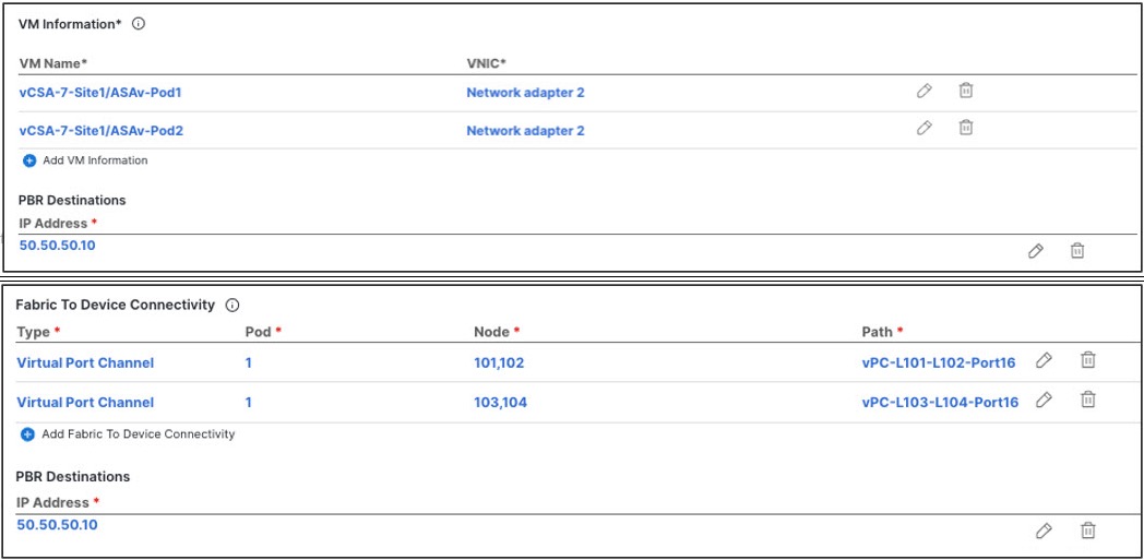
Providing site-level configurations for the Service Device template.
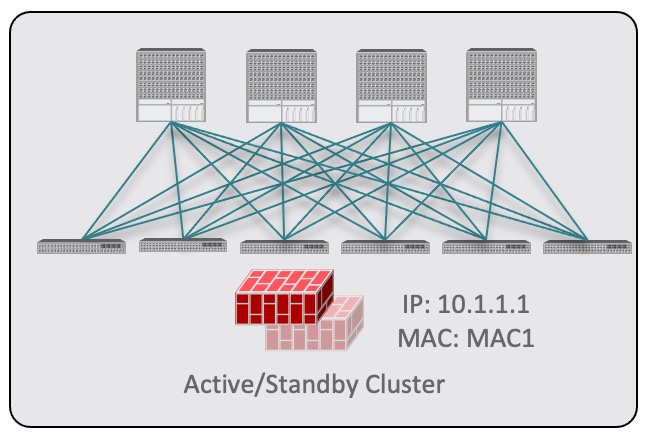
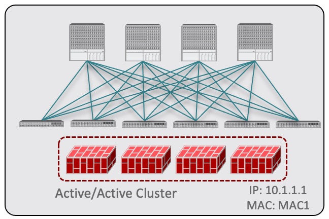
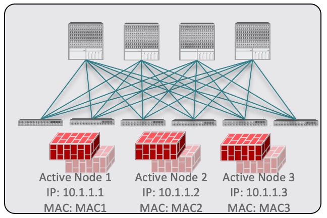
Each site can have its own service device configuration including different high-availability models (such as active/active, active/standby, or independent service nodes).
-
Associating the service device you defined to the contract used for the intersite L3Out use case you deployed in the previous step.
-
 Note |
Please refer ACI Contract Guide and ACI PBR White Paper to understand Cisco ACI contract and PBR terminologies. |
Traffic Flow
This section summarizes the traffic flow between two external EPGs in different sites.
 Note |
In this case, the traffic flow in both directions is redirected through both firewalls in order to avoid asymmetric traffic flows due to independent FW services deployed in the two sites. |
Consumer-to-Provider Traffic Flow
Because any IP prefix associated with the destination external EPG for classification purposes is automatically programmed (with its Class-ID) on the consumer leaf switch, the leaf switch can always resolve the class-ID of the destination external EPG and apply the PBR policy redirecting the traffic to the local FW.
After the firewall on the consumer site has applied its security policy, the traffic is sent back into the fabric and forwarded across sites towards the provider border leaf nodes connecting to the external destination. The border leaf node receiving the traffic originated from Site1 applies the PBR policy and redirects the traffic to the local firewall node. After the firewall applies its local security policy, the traffic is sent back to the border leaf nodes, which can now simply forward it toward the external destination.

Provider-to-Consumer Traffic Flow
Similarly to the consumer-to-provider, the provider leaf switch can always resolve the class-ID of the destination external EPG and apply the PBR policy redirecting the traffic to the local FW in the other direction as well.
The traffic is then sent to the consumer site, where it is steered towards the local firewall before being forwarded to the external destination.


 Feedback