
About the Firewall Mode
The threat defense supports two firewall modes for regular firewall interfaces: Routed Firewall mode and Transparent Firewall mode.
About Routed Firewall Mode
In routed mode, the threat defense device is considered to be a router hop in the network. Each interface that you want to route between is on a different subnet.
About Transparent Firewall Mode
Traditionally, a firewall is a routed hop and acts as a default gateway for hosts that connect to one of its screened subnets. A transparent firewall, on the other hand, is a Layer 2 firewall that acts like a “bump in the wire,” or a “stealth firewall,” and is not seen as a router hop to connected devices. However, like any other firewall, access control between interfaces is controlled, and all of the usual firewall checks are in place.
Layer 2 connectivity is achieved by using a "bridge group" where you group together the inside and outside interfaces for a network, and the threat defense device uses bridging techniques to pass traffic between the interfaces. Each bridge group includes a Bridge Virtual Interface (BVI) to which you assign an IP address on the network. You can have multiple bridge groups for multiple networks. In transparent mode, these bridge groups cannot communicate with each other.
Using the Transparent Firewall in Your Network
The threat defense device connects the same network between its interfaces. Because the firewall is not a routed hop, you can easily introduce a transparent firewall into an existing network.
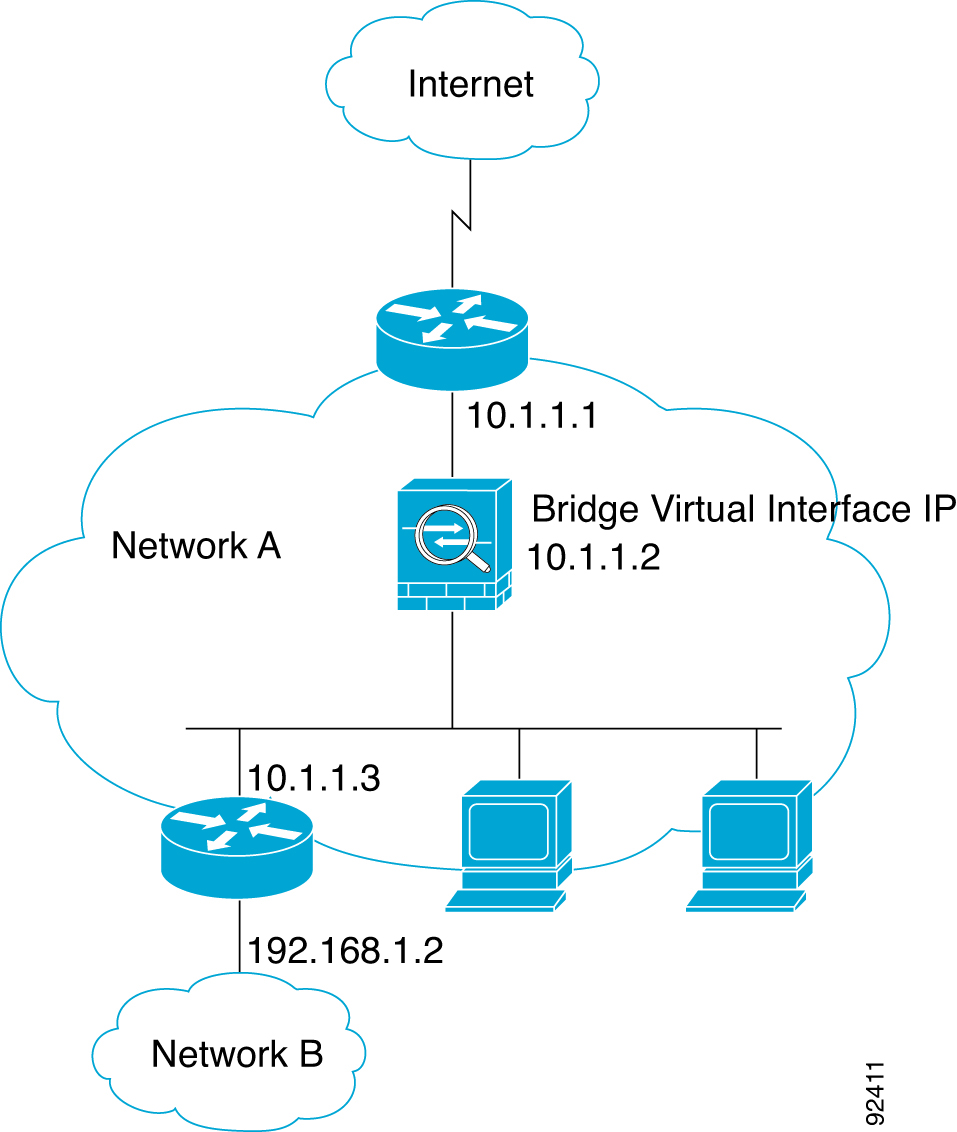
The following figure shows a typical transparent firewall network where the outside devices are on the same subnet as the inside devices. The inside router and hosts appear to be directly connected to the outside router.
Passing Traffic For Routed-Mode Features
For features that are not directly supported on the transparent firewall, you can allow traffic to pass through so that upstream and downstream routers can support the functionality. For example, by using an access rule, you can allow DHCP traffic (instead of the unsupported DHCP relay feature) or multicast traffic such as that created by IP/TV. You can also establish routing protocol adjacencies through a transparent firewall; you can allow OSPF, RIP, EIGRP, or BGP traffic through based on an access rule. Likewise, protocols like HSRP or VRRP can pass through the threat defense device.
About Bridge Groups
A bridge group is a group of interfaces that the threat defense device bridges instead of routes. Bridge groups are only supported in Transparent Firewall Mode. Like any other firewall interfaces, access control between interfaces is controlled, and all of the usual firewall checks are in place.
Bridge Virtual Interface (BVI)
Each bridge group includes a Bridge Virtual Interface (BVI). The threat defense device uses the BVI IP address as the source address for packets originating from the bridge group. The BVI IP address must be on the same subnet as the bridge group member interfaces. The BVI does not support traffic on secondary networks; only traffic on the same network as the BVI IP address is supported.
Only bridge group member interfaces are named and can be used with interface-based features.
Bridge Groups in Transparent Firewall Mode
Bridge group traffic is isolated from other bridge groups; traffic is not routed to another bridge group within the threat defense device, and traffic must exit the threat defense device before it is routed by an external router back to another bridge group in the threat defense device. Although the bridging functions are separate for each bridge group, many other functions are shared between all bridge groups. For example, all bridge groups share a syslog server or AAA server configuration.
You can include multiple interfaces per bridge group. See Guidelines for Firewall Mode for the exact number of bridge groups and interfaces supported. If you use more than 2 interfaces per bridge group, you can control communication between multiple segments on the same network, and not just between inside and outside. For example, if you have three inside segments that you do not want to communicate with each other, you can put each segment on a separate interface, and only allow them to communicate with the outside interface. Or you can customize the access rules between interfaces to allow only as much access as desired.
The following figure shows two networks connected to the threat defense device, which has two bridge groups.

Bridge Groups in Routed Firewall Mode
Bridge group traffic can be routed to other bridge groups or routed interfaces. You can choose to isolate bridge group traffic by not assigning a name to the BVI interface for the bridge group. If you name the BVI, then the BVI participates in routing like any other regular interface.
One use for a bridge group in routed mode is to use extra interfaces on the threat defense instead of an external switch. For example, the default configuration for some devices include an outside interface as a regular interface, and then all other interfaces assigned to the inside bridge group. Because the purpose of this bridge group is to replace an external switch, you need to configure an access policy so all bridge group interfaces can freely communicate.

Allowing Layer 3 Traffic
-
Unicast IPv4 and IPv6 traffic requires an access rule to be allowed through the bridge group.
-
ARPs are allowed through the bridge group in both directions without an access rule. ARP traffic can be controlled by ARP inspection.
-
IPv6 neighbor discovery and router solicitation packets can be passed using access rules.
-
Broadcast and multicast traffic can be passed using access rules.
Allowed MAC Addresses
The following destination MAC addresses are allowed through the bridge group if allowed by your access policy (see Allowing Layer 3 Traffic). Any MAC address not on this list is dropped.
-
TRUE broadcast destination MAC address equal to FFFF.FFFF.FFFF
-
IPv4 multicast MAC addresses from 0100.5E00.0000 to 0100.5EFE.FFFF
-
IPv6 multicast MAC addresses from 3333.0000.0000 to 3333.FFFF.FFFF
-
BPDU multicast address equal to 0100.0CCC.CCCD
BPDU Handling
To prevent loops using the Spanning Tree Protocol, BPDUs are passed by default.
By default BPDUs are also forwarded for advanced inspection, which is unnecessary for this type of packet, and which can cause problems if they are blocked due to an inspection restart, for example. We recommend that you always exempt BPDUs from advanced inspection. To do so, use FlexConfig to configure an EtherType ACL that trusts BPDUs and exempts them from advanced inspection on each member interface. See .
The FlexConfig object should deploy the following commands, where you replace <if-name> with an interface name. Add as many access-group commands as needed to cover each bridge group member interface on the device. You can also choose a different name for the ACL.
access-list permit-bpdu ethertype trust bpdu
access-group permit-bpdu in interface <if-name>
MAC Address vs. Route Lookups
For traffic within a bridge group, the outgoing interface of a packet is determined by performing a destination MAC address lookup instead of a route lookup.
Route lookups, however, are necessary for the following situations:
-
Traffic originating on the threat defense device—Add a default/static route on the threat defense device for traffic destined for a remote network where a syslog server, for example, is located.
-
Voice over IP (VoIP) and TFTP traffic, and the endpoint is at least one hop away—Add a static route on the threat defense device for traffic destined for the remote endpoint so that secondary connections are successful. The threat defense device creates a temporary "pinhole" in the access control policy to allow the secondary connection; and because the connection might use a different set of IP addresses than the primary connection, the threat defense device needs to perform a route lookup to install the pinhole on the correct interface.
Affected applications include:
-
H.323
-
RTSP
-
SIP
-
Skinny (SCCP)
-
SQL*Net
-
SunRPC
-
TFTP
-
-
Traffic at least one hop away for which the threat defense device performs NAT—Configure a static route on the threat defense device for traffic destined for the remote network. You also need a static route on the upstream router for traffic destined for the mapped addresses to be sent to the threat defense device.
This routing requirement is also true for embedded IP addresses for VoIP and DNS with NAT enabled, and the embedded IP addresses are at least one hop away. The threat defense device needs to identify the correct egress interface so it can perform the translation.
Figure 4. NAT Example: NAT within a Bridge Group 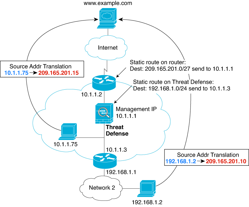
Unsupported Features for Bridge Groups in Transparent Mode
The following table lists the features are not supported in bridge groups in transparent mode.
|
Feature |
Description |
|---|---|
|
Dynamic DNS |
— |
|
DHCP relay |
The transparent firewall can act as a DHCPv4 server, but it does not support DHCP relay. DHCP relay is not required because you can allow DHCP traffic to pass through using two access rules: one that allows DCHP requests from the inside interface to the outside, and one that allows the replies from the server in the other direction. |
|
Dynamic routing protocols |
You can, however, add static routes for traffic originating on the threat defense device for bridge group member interfaces. You can also allow dynamic routing protocols through the threat defense device using an access rule. |
|
Multicast IP routing |
You can allow multicast traffic through the threat defense device by allowing it in an access rule. |
|
QoS |
— |
Unsupported Features for Bridge Groups in Routed Mode
The following table lists the features are not supported in bridge groups in routed mode.
|
Feature |
Description |
|---|---|
|
EtherChannel member interfaces |
Only physical interfaces, redundant interfaces, and subinterfaces are supported as bridge group member interfaces. Management interfaces are also not supported. |
|
Clustering |
Bridge groups are not supported in clustering. |
|
Dynamic DNS |
— |
|
DHCP relay |
The routed firewall can act as a DHCPv4 server, but it does not support DHCP relay on BVIs or bridge group member interfaces. |
|
Dynamic routing protocols |
You can, however, add static routes for BVIs. You can also allow dynamic routing protocols through the threat defense device using an access rule. Non-bridge group interfaces support dynamic routing. |
|
Multicast IP routing |
You can allow multicast traffic through the threat defense device by allowing it in an access rule. Non-bridge group interfaces support multicast routing. |
|
QoS |
Non-bridge group interfaces support QoS. |
|
VPN termination for through traffic |
You cannot terminate a VPN connection on the BVI. Non-bridge group interfaces support VPN. Bridge group member interfaces support site-to-site VPN tunnels for management connections only. It does not terminate VPN connections for traffic through the threat defense device. You can pass VPN traffic through the bridge group using an access rule, but it does not terminate non-management connections. |

 Feedback