FlexConfig Policies for FTD

The following topics describe how to configure and deploy FlexConfig policies.

FlexConfig Policy Overview

A FlexConfig policy is a container of an ordered list of FlexConfig objects. Each object includes a series of Apache Velocity scripting language commands, ASA software configuration commands, and variables that you define. The contents of each FlexConfig object is essentially a program that generates a sequence of ASA commands that will then be deployed to the assigned devices. This command sequence then configures the related feature on the Firepower Threat Defense device.

Firepower Threat Defense uses ASA configuration commands to implement some features, but not all features. There is no unique set of Firepower Threat Defense configuration commands. Instead, the point of FlexConfig is to allow you to configure features that are not yet directly supported through Firepower Management Center policies and settings.


Caution


Cisco strongly recommends using FlexConfig policies only if you are an advanced user with a strong ASA background and at your own risk. You may configure any commands that are not prohibited. Enabling features through FlexConfig policies may cause unintended results with other configured features.

You may contact the Cisco Technical Assistance Center for support concerning FlexConfig policies that you have configured. The Cisco Technical Assistance Center does not design or write custom configurations on any customer's behalf. Cisco expresses no guarantees for correct operation or interoperability with other Firepower System features. FlexConfig features may become deprecated at any time. For fully guaranteed feature support, you must wait for Firepower Management Center support. When in doubt, do not use FlexConfig policies.


Recommended Usage for FlexConfig Policies

There are two main recommended uses for FlexConfig:

  • You are converting from ASA to Firepower Threat Defense, and there are compatible features you are using (and need to continue using) that Firepower Management Center does not directly support. In this case, use the show running-config command on the ASA to see the configuration for the feature and create your FlexConfig objects to implement it. Experiment with the object’s deployment settings (once/everytime and append/prepend) to get the right setting. Verify by comparing show running-config output on the two devices.

  • You are using Firepower Threat Defense but there is a setting or feature that you need to configure, e.g. the Cisco Technical Assistance Center tells you that a particular setting should resolve a specific problem you are encountering. For complicated features, use a lab device to test the FlexConfig and verify that you are getting the expected behavior.

The system includes a set of predefined FlexConfig objects that represent tested configurations. If the feature you need is not represented by these objects, first determine if you can configure an equivalent feature in standard policies. For example, the access control policy includes intrusion detection and prevention, HTTP and other types of protocol inspection, URL filtering, application filtering, and access control, which the ASA implements using separate features. Because many features are not configured using CLI commands, you will not see every policy represented within the output of show running-config .


Note


At all times, keep in mind that there is not a one-to-one overlap between ASA and Firepower Threat Defense. Do not attempt to completely recreate an ASA configuration on a Firepower Threat Defense device. You must carefully test any feature that you configure using FlexConfig.


CLI Commands in FlexConfig Objects

Firepower Threat Defense uses ASA configuration commands to configure some features. Although not all ASA features are compatible with Firepower Threat Defense, there are some features that can work on Firepower Threat Defense but that you cannot configure in Firepower Management Center policies. You can use FlexConfig objects to specify the CLI required to configure these features.

If you decide to use FlexConfig to manually configure a feature, you are responsible for knowing and implementing the commands according to the proper syntax. FlexConfig policies do not validate CLI command syntax. For more information about proper syntax and configuring CLI commands, use the ASA documentation as a reference:

The following topics explain more about configuration commands.

Determine the ASA Software Version and Current CLI Configuration

Because the system uses ASA software commands to configure some features, you need to determine the current ASA version used in software running on the Firepower Threat Defense device. This version number indicates which ASA CLI configuration guides to use for instructions on configuring a feature. You also should examine the current CLI-based configuration and compare it to the ASA configuration you want to implement.

Keep in mind that any ASA configuration will be very different from a Firepower Threat Defense configuration. Many Firepower Threat Defense policies are configured outside of the CLI, so you cannot see the configuration by looking at the commands. Do not try to create a one-to-one correspondence between an ASA and Firepower Threat Defense configuration.

To view this information, make an SSH connection to the device's management interface and issue the following commands:

  • show version system and look for the Cisco Adaptive Security Appliance Software Version number. (If you issue the command through the Firepower Management Center CLI tool, omit the system keyword.)

  • show running-config to view the current CLI configuration.

  • show running-config all to include all the default commands in the current CLI configuration.

You can also issue these commands from within Firepower Management Center using the following procedure.

Procedure

Step 1

Choose System > Health > Monitor.

Step 2

Click the name of the device targeted by the FlexConfig policy.

You might need to click the open/close arrow in the Count column in the Status table to see any devices.

Step 3

Choose Advanced Troubleshooting.

Step 4

Choose Threat Defense CLI.

Step 5

Choose show as the command, and type version or one of the other commands as the parameter.

Step 6

Click Execute.

For version, search the output for the Cisco Adaptive Security Appliance Software Version number.

You can select the output and press Ctrl+C, then paste it into a text file for later analysis.


Prohibited CLI Commands

The purpose of FlexConfig is to configure features that are available on ASA devices that you cannot configure on Firepower Threat Defense devices using Firepower Management Center.

Thus, you are prevented from configuring ASA features that have equivalents in Firepower Management Center. The following table lists some of these prohibited command areas.

In addition, some clear commands are prohibited because they overlap with managed policies, and can delete part of the configuration for a managed policy.

The FlexConfig object editor prevents you from including prohibited commands in the object.

Prohibited CLI Command

Description

AAA

Configuration blocked.

AAA-Server

Configuration blocked.

Access-list

Advanced ACL, Extended ACL, and Standard ACL are blocked. Ethertype ACL is allowed.

You can use standard and extended ACL objects defined in the object manager inside the template as variables.

ARP Inspection

Configuration blocked.

As-path Object

Configuration blocked.

Banner

Configuration blocked.

BGP

Configuration blocked.

Clock

Configuration blocked.

Community-list Object

Configuration blocked.

Copy

Configuration blocked.

Delete

Configuration blocked.

DHCP

Configuration blocked.

Enable Password

Configuration blocked.

Erase

Configuration blocked.

Fragment Setting

Blocked, except for fragment reassembly .

Fsck

Configuration blocked.

HTTP

Configuration blocked.

ICMP

Configuration blocked.

Interface

Only nameif, mode, shutdown, ip address and mac-address commands are blocked.

Multicast Routing

Configuration blocked.

NAT

Configuration blocked.

Network Object/Object-group

Network object creation in the FlexConfig object is blocked, but you can use network objects and groups defined in the object manager inside the template as variables.

NTP

Configuration blocked.

OSPF/OSPFv3

Configuration blocked.

pager

Configuration blocked.

Password Encryption

Configuration blocked.

Policy-list Object

Configuration blocked.

Prefix-list Object

Configuration blocked.

Reload

You cannot schedule reloads. The system does not use the reload command to restart the system, it uses the reboot command.

RIP

Configuration blocked.

Route-Map Object

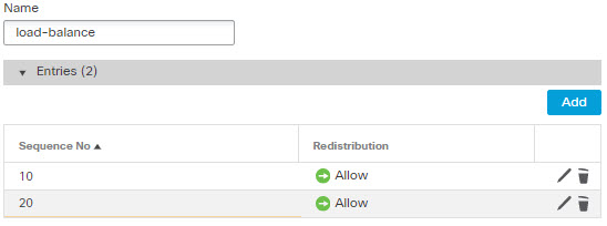
Route-map object creation in the FlexConfig object is blocked, but you can use route map objects defined in the object manager inside the template as variables.

Service Object/Object-group

Service object creation in the FlexConfig object is blocked, but you can use port objects defined in the object manager inside the template as variables.

SNMP

Configuration blocked.

SSH

Configuration blocked.

Static Route

Configuration blocked.

Syslog

Configuration blocked.

Time Synchronization

Configuration blocked.

Timeout

Configuration blocked.

VPN

Configuration blocked.

Template Scripts

You can use scripting language to control processing within a FlexConfig object. Scripting language instructions are a subset of commands supported in the Apache Velocity 1.3.1 template engine, a Java-based scripting language that supports looping, if/else statements, and variables.

To learn how to use the scripting language, see the Velocity Developer Guide at http://velocity.apache.org/engine/devel/developer-guide.html.

FlexConfig Variables

You can use variables in a FlexConfig object in cases where part of a command or processing instruction depends on runtime information rather than static information. During deployment, the variables are replaced with strings obtained from other configurations for the device based on the type of variable:

  • Policy object variables are replaced with strings obtained from objects defined in Firepower Management Center.

  • System variables are replaced with information obtained from the device itself or from policies configured for it.

  • Processing variables are loaded with the contents of policy object or system variables as scripting commands are processed. For example, in a loop, you iteratively load one value from a policy object or system variable into a processing variable, then use the processing variable to form a command string or perform some other action. These processing variables do not show up in the Variables list within a FlexConfig object. Also, you do not add them using the Insert menu in the FlexConfig object editor.

  • Secret key variables are replaced with the single string defined for the variable within the FlexConfig object.

Variables start with the $ character, except for secret keys, which start with the @ character. For example, $ifname is a policy object variable in the following command, whereas @keyname is a secret key.


interface $ifname 
key @keyname


Note


The first time you insert a policy object or system variable, you must do so through the Insert menu in the FlexConfig object editor. This action adds the variable to the Variables list at the bottom of the FlexConfig object editor. But you must type in the variable string on subsequent uses, even when using system variables. If you are adding a processing variable, which does not have an object or system variable assignment, do not use the Insert menu. If you are adding a secret key, always use the Insert menu. Secret key variables do not show up in the Variables list.


Whether a variable is resolved as a single string, a list of strings, or a table of values depends on the type of policy object or system variable you assign to the variable. (Secret keys always resolve to a single string.) You must understand what will be returned in order to process the variables correctly.

The following topics explain the various types of variable and how to process them.

How to Process Variables

At runtime, a variable can resolve to a single string, a list of strings of the same type, a list of strings of different types, or a table of named values. In addition, variables that resolve to multiple values can be of determinate or indeterminate length. You must understand what will be returned in order to process the values correctly.

Following are the main possibilities.

Single Value Variables

If a variable always resolves to a single string, use the variable directly without modification in the FlexConfig script.

For example, the predefined text variable tcpMssBytes always resolves to a single value (which must be numeric). The Sysopt_basic FlexConfig then uses an if/then/else structure to set the maximum segment size based on the value of another single-value text variable, tcpMssMinimum:


#if($tcpMssMinimum == "true")
  sysopt connection tcpmss minimum $tcpMssBytes 
#else
  sysopt connection tcpmss $tcpMssBytes 
#end

In this example, you would use the Insert menu in the FlexConfig object editor to add the first use of $tcpMssBytes, but you would type in the variable directly on the #else line.

Secret key variables are a special type of single value variable. For secret keys, you always use the Insert menu to add the variable, even for second and subsequent uses. These variables do not show up in the Variables list within the FlexConfig object. For example, if you wanted to hide the keys for EIGRP configuration, you could copy the Eigrp_Interface_Configure FlexConfig, and replace the $eigrpAuthKey and $eigrpAuthKeyId variables with secret keys, @SecretEigrpAuthKey and @SecretEigrpAuthKeyId.


authentication key eirgp $eigrpAS @SecretEigrpAuthKey key-id @SecretEigrpAuthKeyId


Note


Policy object variables for network objects also equate to a single IP address specification, either a host address, network address, or address range. However, in this case, you must know what type of address to expect, because the ASA commands require specific address types. For example, if a command requires a host address, using a network object variable that points to an object that contains a network address will result in an error during deployment.


Multiple Value Variables, All Values Are the Same Type

Several policy object and system variables resolve to multiple values of the same type. For example, an object variable that points to a network object group resolves to a list of the IP addresses within the group. Similarly, the system variable $SYS_FW_INTERFACE_NAME_LIST resolves to a list of interface names.

You can also create text objects for multiple values of the same type. For example, the predefined text object enableInspectProtocolList can contain more than one protocol name.

Multiple value variables that resolve to a list of items of the same type are frequently of indeterminate length. For example, you cannot know beforehand how many interfaces on a device are named, as users can configure or unconfigure interfaces at any time.

Thus, you would typically use a loop to process multiple value variables of the same type. For example, the predefined FlexConfig Default_Inspection_Protocol_Enable uses a #foreach loop to go through the enableInspectProtocolList object and process each value.


policy-map global_policy
    class inspection_default
    #foreach ( $protocol in $enableInspectProtocolList) 
    inspect $protocol
    #end 

In this example, the script assigns each value in turn to the $protocol variable, which is then used in an ASA inspect command to enable the inspection engine for that protocol. In this case, you simply type in $protocol as a variable name. You do not use the Insert menu to add it, because you are not assigning an object or system value to the variable. However, you must use the Insert menu to add $enableInspectProtocolList.

The system loops through the code between #foreach and #end until there are no values remaining in $enableInspectProtocolList.

Multiple Value Variables, Values Are Different Types

You can create multiple value text objects, but have each value serve a different purpose. For example, the predefined netflow_Destination text object should have 3 values, in order, interface name, destination IP address, and UDP port number.

Objects defined in this way should have a determinate number of values. Otherwise, they would be hard to process.

Use the get method to process these objects. Type .get(n) at the end of the object name, replacing n with an index into the object. Start counting at 0, even though the text object lists its values starting at 1.

For example, the Netflow_Add_Destination object uses the following line to add the 3 values from netflow_Destination to the ASA flow-export command.


flow-export destination $netflow_Destination.get(0) $netflow_Destination.get(1) 
$netflow_Destination.get(2) 

In this example, you would use the Insert menu in the FlexConfig object editor to add the first use of $netflow_Destination, and then add .get(0). But you would type in the variable directly for the $netflow_Destination.get(1) and $netflow_Destination.get(2) specifications.

Multiple Value Variables that Resolve to a Table of Values

Some system variables return a table of values. These variables include MAP in their name, for example, $SYS_FTD_ROUTED_INTF_MAP_LIST. The routed interface map returns data that looks like the following (line returns added for clarity):


[{intf_hardwarare_id=GigabitEthernet0/0, intf_ipv6_eui64_addresses=[],
intf_ipv6_prefix_addresses=[], intf_subnet_mask_v4=255.255.255.0,
intf_ip_addr_v4=10.100.10.1, intf_ipv6_link_local_address=, 
intf_logical_name=outside},

{intf_hardwarare_id=GigabitEthernet0/1, intf_ipv6_eui64_addresses=[],
intf_ipv6_prefix_addresses=[], intf_subnet_mask_v4=255.255.255.0,
intf_ip_addr_v4=10.100.11.1, intf_ipv6_link_local_address=, 
intf_logical_name=inside},

{intf_hardwarare_id=GigabitEthernet0/2, intf_ipv6_eui64_addresses=[], 
intf_ipv6_prefix_addresses=[], intf_subnet_mask_v4=, intf_ip_addr_v4=, 
intf_ipv6_link_local_address=, intf_logical_name=}, 

{intf_hardwarare_id=Management0/0, intf_ipv6_eui64_addresses=[], 
intf_ipv6_prefix_addresses=[], intf_subnet_mask_v4=, intf_ip_addr_v4=, 
intf_ipv6_link_local_address=, intf_logical_name=diagnostic}]

In the above example, information is returned for 4 interfaces. Each interface includes a table of named values. For example, intf_hardwarare_id is the name of the interface hardware name property, and returns strings such as GigabitEthernet0/0.

This type of variable is typically of indeterminate length, so you need to use looping to process the values. But you also need to add the property name to the variable name to indicate which value to retrieve.

For example, IS-IS configuration requires that you add the ASA isis command to an interface that has a logical name in interface configuration mode. However, you enter that mode using the interface’s hardware name. Thus, you need to identify which interfaces have logical names, then configure just those interfaces using their hardware names. The ISIS_Interface_Configuration predefined FlexConfig does this using an if/then structure nested in a loop. In the following code, you can see that the #foreach scripting command loads each interface map into the $intf variable, then the #if statement keys off the intf_logical_name value in the map ($intf.intf_logical_name), and if the value is in the list defined in the isisIntfList predefined text variable, enters the interface command using the intf_hardwarare_id value ($intf.intf_hardwarare_id). You would need to edit the isisIntfList variable to add the names of the interfaces on which to configure IS-IS.


#foreach ($intf in $SYS_FTD_ROUTED_INTF_MAP_LIST)
 #if ($isIsIntfList.contains($intf.intf_logical_name))
  interface $intf.intf_hardwarare_id 
   isis
   #if ($isIsAddressFamily.contains("ipv6"))
   ipv6 router isis
   #end
 #end
#end

How to See What a Variable Will Return for a Device

An easy way to evaluate what a variable will return is to create a simple FlexConfig object that does nothing more than process an annotated list of variables. Then, you can assign it to a FlexConfig policy, assign the policy to a device, save the policy, then preview the configuration for that device. The preview will show the resolved values. You can select the preview text, press Ctrl+C, then paste the output into a text file for analysis.


Note


Do not deploy this FlexConfig to the device, however, because it will not contain any valid configuration commands. You would get deployment errors. After obtaining the preview, delete the FlexConfig object from the FlexConfig policy and save the policy.


For example, you could construct the following FlexConfig object:


Following is a network object group variable for the 
IPv4-Private-All-RFC1918 object:

$IPv4_Private_addresses

Following is the system variable SYS_FW_MANAGEMENT_IP:

$SYS_FW_MANAGEMENT_IP

Following is the system variable SYS_FW_ENABLED_INSPECT_PROTOCOL_LIST:

$SYS_FW_ENABLED_INSPECT_PROTOCOL_LIST

Following is the system variable SYS_FTD_ROUTED_INTF_MAP_LIST:

$SYS_FTD_ROUTED_INTF_MAP_LIST

Following is the system variable SYS_FW_INTERFACE_NAME_LIST:

$SYS_FW_INTERFACE_NAME_LIST

The preview of this object might look like the following (line returns added for clarity):


###Flex-config Prepended CLI ###

###CLI generated from managed features ###

###Flex-config Appended CLI ###
Following is an network object group variable for the 
IPv4-Private-All-RFC1918 object:

[10.0.0.0, 172.16.0.0, 192.168.0.0]

Following is the system variable SYS_FW_MANAGEMENT_IP:

192.168.0.171

Following is the system variable SYS_FW_ENABLED_INSPECT_PROTOCOL_LIST:

[dns, ftp, h323 h225, h323 ras, rsh, rtsp, sqlnet, skinny, sunrpc, 
xdmcp, sip, netbios, tftp, icmp, icmp error, ip-options]

Following is the system variable SYS_FTD_ROUTED_INTF_MAP_LIST:

[{intf_hardwarare_id=GigabitEthernet0/0, intf_ipv6_eui64_addresses=[], 
intf_ipv6_prefix_addresses=[], intf_subnet_mask_v4=255.255.255.0, 
intf_ip_addr_v4=10.100.10.1, intf_ipv6_link_local_address=, 
intf_logical_name=outside}, 

{intf_hardwarare_id=GigabitEthernet0/1, intf_ipv6_eui64_addresses=[], 
intf_ipv6_prefix_addresses=[], intf_subnet_mask_v4=255.255.255.0, 
intf_ip_addr_v4=10.100.11.1, intf_ipv6_link_local_address=, 
intf_logical_name=inside}, 

{intf_hardwarare_id=GigabitEthernet0/2, intf_ipv6_eui64_addresses=[], 
intf_ipv6_prefix_addresses=[], intf_subnet_mask_v4=, intf_ip_addr_v4=, 
intf_ipv6_link_local_address=, intf_logical_name=}, 

{intf_hardwarare_id=Management0/0, intf_ipv6_eui64_addresses=[], 
intf_ipv6_prefix_addresses=[], intf_subnet_mask_v4=, intf_ip_addr_v4=, 
intf_ipv6_link_local_address=, intf_logical_name=diagnostic}]

Following is the system variable SYS_FW_INTERFACE_NAME_LIST:

[outside, inside, diagnostic]


FlexConfig Policy Object Variables

A policy object variable is associated with a specific policy object configured in the Object Manager. When you insert a policy object variable in a FlexConfig object, you give the variable a name and select the object associated with it.

Although you can give the variable the exact same name as the associated object, the variable itself is not the same thing as the associated object. You must use the Insert > Insert Policy Object > Object Type menu in the FlexConfig object editor to add the variable for the first time to the script in the FlexConfig to establish the association with the object. Simply typing in the name of the object preceded by a $ sign does not create a policy object variable.

You can create variables to point to the following types of object. Ensure that you create the right type of object for each variable. To create objects, go to the Objects > Object Management page.

  • Text Objects—For text strings, which can include IP addresses, numbers, and other free-form text such as interface or zone names. Select FlexConfig > Text Object from the table of contents, then click Add Text Object. You can configure these objects to contain a single value or multiple values. These objects are highly flexible and built specifically for use within FlexConfig objects. For detailed information, see Configure FlexConfig Text Objects.

  • Network—For IP addresses. You can use network objects or groups. Select Network from the table of contents, then select Add Network > Add Object or Add Group. If you use a group object, the variable returns a list of each IP address specification within the group. Addresses can be host, network, or address ranges, depending on the object contents. See Network Objects.

  • Security Zones—For interfaces within a security zone or interface group. Select Interface from the table of contents, then select Add > Security Zone or Interface Group. A security zone variable returns a list of the interfaces within that zone or group for the device being configured. See Interface Objects: Interface Groups and Security Zones.

  • Standard ACL Object—For standard access control lists. A standard ACL variable returns the name of the standard ACL object. Select Access List > Standard from the table of contents, then click Add Standard Access List Object. See Access List.

  • Extended ACL Object—For extended access control lists. An extended ACL variable returns the name of the extended ACL object. Select Access List > Extended from the table of contents, then click Add Extended Access List Object. See Access List.

  • Route Map—For route map objects. A route map variable returns the name of the route map object. Select Route Map from the table of contents, then click Add Route Map. See Route Maps.

FlexConfig System Variables

System variables are replaced with information obtained from the device itself or from policies configured for it.

You must use the Insert > Insert System Variable > Variable Name menu in the FlexConfig object editor to add the variable for the first time to the script in the FlexConfig to establish the association with the system variable. Simply typing in the name of the system variable preceded by a $ sign does not create a system variable within the context of the FlexConfig object.

The following table explains the available system variables. Before using a variable, examine what is typically returned for the variable; see How to See What a Variable Will Return for a Device.

Name

Description

SYS_FW_OS_MODE

The operating system mode of the device. Possible values are ROUTED or TRANSPARENT.

SYS_FW_OS_MULTIPLICITY

Whether the device is running in single or multiple context mode. Possible values are SINGLE, MULTI, or NOT_APPLICABLE.

SYS_FW_MANAGEMENT_IP

The management IP address of the device

SYS_FW_HOST_NAME

The device hostname

SYS_FTD_INTF_POLICY_MAP

A map with interface name as key and policy-map as value. This variable returns nothing if there are no interface-based service policies defined on the device.

SYS_FW_ENABLED_INSPECT_PROTOCOL_LIST

The list of protocols for which inspection is enabled.

SYS_FTD_ROUTED_INTF_MAP_LIST

A list of routed interface maps on the device. Each map includes a set of named values related to routed interface configuration.

SYS_FTD_SWITCHED_INTF_MAP_LIST

A list of switched interface maps on the device. Each map includes a set of named values related to switched interface configuration.

SYS_FTD_INLINE_INTF_MAP_LIST

A list of inline interface maps on the device. Each map includes a set of named values related to inline set interface configuration.

SYS_FTD_PASSIVE_INTF_MAP_LIST

A list of passive interface maps on the device. Each map includes a set of named values related to passive interface configuration.

SYS_FTD_INTF_BVI_MAP_LIST

A list of Bridge Virtual Interface maps on the device. Each map includes a set of named values related to BVI configuration.

SYS_FW_INTERFACE_HARDWARE_ID_LIST

A list of the hardware names for interfaces on the device, such as GigabitEthernet0/0.

SYS_FW_INTERFACE_NAME_LIST

A list of logical names for interfaces on the device, such as inside.

SYS_FW_INLINE_INTERFACE_NAME_LIST

A list of logical names for interfaces configured as passive or ERSPAN passive.

SYS_FW_NON_INLINE_INTERFACE_NAME_LIST

A list of logical names for interfaces that are not part of inline sets, such as all routed interfaces.

Predefined FlexConfig Objects

The predefined FlexConfig objects provide tested configurations for select features. Use these objects if you need to configure these features, which otherwise cannot be configured through Firepower Management Center.

The following table lists the available objects. Make note of the associated text objects. You must edit these text objects to customize the behavior of the predefined FlexConfig object. The text objects make it possible for you to customize the configuration using the IP addresses and other attributes required by your network and device.

If you need to modify a predefined FlexConfig object, copy the object, make changes to the copy, and save it with a new name. You cannot directly edit a predefined FlexConfig object.

Although you might be able to configure other ASA-based features using FlexConfig, the configuration of those features has not been tested. If an ASA feature overlaps with something that you can configure in Firepower Management Center policies, do not attempt to configure it through FlexConfig.

For example, Snort inspection includes the HTTP protocol, so do not enable ASA-style HTTP inspection. (In fact, you cannot add http to the enableInspectProtocolList object. In this case, you are prevented from misconfiguring your device.) Instead, configure the access control policy to perform application or URL filtering, as needed, to implement your HTTP inspection requirements.

FlexConfig Object Name

Description

Associated Text Objects

Default_DNS_Configure

(Deprecated.)

Configure the Default DNS group, which defines the DNS servers that can be used when resolving fully-qualified domain names on the data interfaces. This allows you to use commands in the CLI, such as ping , using host names rather than IP addresses.

Starting with version 6.3, configure DNS for the data interfaces in the Firepower Threat Defense Platform Settings policy.

defaultDNSNameServerList, defaultDNSParameters

Default_Inspection_Protocol_Disable

Disables protocols in the global_policy default policy map.

disableInspectProtocolList

Default_Inspection_Protocol_Enable

Enables protocols in the global_policy default policy map.

enableInspectProtocolList

DHCPv6_Prefix_Delegation_Configure

Configure one outside (Prefix Delegation client) and one inside interface (recipient of delegated prefix) for IPv6 prefix delegation. To use this template, copy it and modify the variables.

pdoutside, pdinside

Also uses the system variable SYS_FTD_ROUTED_INTF_MAP_LIST

DHCPv6_Prefix_Delegation_UnConfigure

Removes the DHCPv6 prefix delegation configuration.

pdoutside, pdinside

Also uses the system variable SYS_FTD_ROUTED_INTF_MAP_LIST

DNS_Configure

Configure DNS servers in a non-default DNS server group. Copy the object to change the name of the group.

dnsNameServerList, dnsParameters.

DNS_UnConfigure

Removes the DNS server configuration performed by Default_DNS_Configure and DNS_Configure. Copy the object to change the DNS server group names if you altered DNS_Configure.

Eigrp_Configure

Configures EIGRP routing next-hop, auto-summary, router-id, eigrp-stub.

eigrpAS, eigrpNetworks, eigrpDisableAutoSummary, eigrpRouterId, eigrpStubReceiveOnly, eigrpStubRedistributed, eigrpStubConnected, eigrpStubStatic, eigrpStubSummary

Eigrp_Interface_Configure

Configures EIGRP interface authentication mode, authentication key, hello interval, hold time, split horizon.

eigrpIntfList, eigrpAS, eigrpAuthKey, eigrpAuthKeyId, eigrpHelloInterval, eigrpHoldTime, eigrpDisableSplitHorizon

Also uses the system variable SYS_FTD_ROUTED_INTF_MAP_LIST

Eigrp_Unconfigure

Clears EIGRP configuration for an autonomous system from the device.

Eigrp_Unconfigure_all

Clears all EIGRP configurations.

Inspect_IPv6_Configure

Configures IPv6 inspection in the global_policy policy map, logging and dropping traffic based on IPv6 header contents.

IPv6RoutingHeaderDropLogList, IPv6RoutingHeaderLogList, IPv6RoutingHeaderDropList.

Inspect_IPv6_UnConfigure

Clears and disables IPv6 inspection.

ISIS_Configure

Configures global parameters for IS-IS routing.

isIsNet, isIsAddressFamily, isISType

ISIS_Interface_Configuration

Interface level IS-IS configuration.

isIsAddressFamily, IsIsIntfList

Also uses the system variable SYS_FTD_ROUTED_INTF_MAP_LIST

ISIS_Unconfigure

Clears the IS-IS router configuration on the device.

ISIS_Unconfigure_All

Clears the IS-IS router configuration from the device, including the router assignment from the device interface.

Netflow_Add_Destination

Creates and configures a Netflow export destination.

Netflow_Destinations, netflow_Event_Types

Netflow_Clear_Parameters

Restores Netflow export global default settings.

Netflow_Delete_Destination

Deletes a Netflow export destination.

Netflow_Destinations, netflow_Event_Types

Netflow_Set_Parameters

Sets global parameters for Netflow export.

netflow_Parameters

NGFW_TCP_NORMALIZATION

Modifies the default TCP normalization configuration.

Policy_Based_Routing

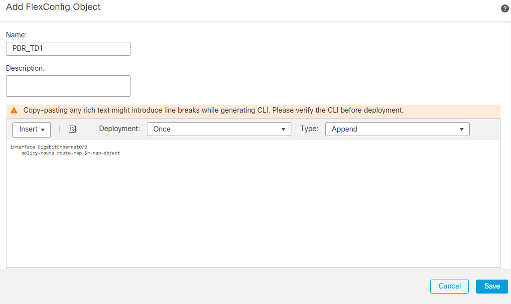
To use this example configuration, copy it, modify the interface name, and use the r-map-object text object to identify a route map object in the object manager.

Policy_Based_Routing_Clear

Clears Policy Based Routing configurations from the device.

Sysopt_AAA_radius

Ignores the authentication key in RADIUS accounting responses.

Sysopt_AAA_radius_negate

Negates the Sysopt_AAA_radius configuration.

Sysopt_basic

Configures sysopt wait time , maximum segment size for TCP packets, and detailed traffic statistics.

tcpMssMinimum, tcpMssBytes

Sysopt_basic_negate

Clears sysopt_basic detailed traffic statistics, wait time, and TCP maximum segment size.

Sysopt_clear_all

Clears all sysopt configurations from the device.

Sysopt_noproxyarp

Configures noproxy-arp CLIs.

Uses system variable SYS_FW_NON_INLINE_INTF_NAME_LIST

Sysopt_noproxyarp_negate

Clears Sysopt_noproxyarp configurations.

Uses system variable SYS_FW_NON_INLINE_INTF_NAME_LIST

Sysopt_Preserve_Vpn_Flow

Configures syopt preserve VPN flow.

Sysopt_Preserve_Vpn_Flow_negate

Clears the Sysopt_Preserve_Vpn_Flow configuration.

Sysopt_Reclassify_Vpn

Configures sysopt reclassify vpn.

Sysopt_Reclassify_Vpn_Negate

Negates sysopt reclassify vpn.

TCP_Embryonic_Conn_Limit

(Deprecated.)

Configures embryonic connection limits to protect against SYN Flood Denial of Service (DoS) attacks.

Starting with version 6.3, configure these features in the Firepower Threat Defense Service Policy, which you can find on the Advanced tab of the access control policy assigned to the device.

tcp_conn_misc, tcp_conn_limit

TCP_Embryonic_Conn_Timeout

(Deprecated.)

Configures embryonic connection timeouts to protect against SYN Flood Denial of Service (DoS) attacks.

Starting with version 6.3, configure these features in the Firepower Threat Defense Service Policy, which you can find on the Advanced tab of the access control policy assigned to the device.

tcp_conn_misc, tcp_conn_timeout

Threat_Detection_Clear

Clear the threat detection TCP Intercept configuration.

Threat_Detection_Configure

Configure threat detection statistics for attacks intercepted by TCP Intercept.

threat_detection_statistics

VxLAN_Clear_Nve

Removes the NVE 1 configured when VxLAN_Configure_Port_And_Nve is used from the device.

VxLAN_Clear_Nve_Only

Clears the NVE configured on the interface when deployed.

VxLAN_Configure_Port_And_Nve

Configures VLAN port and NVE 1.

vxlan_Port_And_Nve

VxLAN_Make_Nve_Only

Sets an interface for NVE only.

vxlan_Nve_Only

Also uses system variables SYS_FTD_ROUTED_MAP_LIST and SYS_FTD_SWITCHED_INTF_MAP_LIST

VxLAN_Make_Vni

Creates a VNI interface. After deploying this you have to unregister and re-register the device to properly discover the VNI interface.

vxlan_Vni

Wccp_Configure

This template provides an example for configuring WCCP.

isServiceIdentifier, serviceIdentifier, wccpPassword

Wccp_Configure_Clear

Clears WCCP configurations.

Predefined Text Objects

There are several predefined text objects. These objects are associated with variables used in the predefined FlexConfig objects. In most cases, you must edit these objects to add values if you use the associated FlexConfig object, or you will see errors during deployment. Although some of these objects contain default values, others are empty.

For information on editing text objects, see Configure FlexConfig Text Objects.

Name

Description

Associated FlexConfig Object

defaultDNSNameServerList

(Deprecated.)

The DNS server IP address to configure in the Default DNS group.

Starting with version 6.3, configure DNS for the data interfaces in the Firepower Threat Defense Platform Settings policy.

Default_DNS_Configure

defaultDNSParameters

(Deprecated.)

The parameters to control DNS behavior for the default DNS server group. The object contains separate entries, in order, for retries, timeout, expire-entry-timer, poll-timer, domain-name.

Starting with version 6.3, configure DNS for the data interfaces in the Firepower Threat Defense Platform Settings policy.

Default_DNS_Configure

disableInspectProtocolList

Disables protocols in the default policy map (global_policy).

Disable_Default_Inspection_Protocol

dnsNameServerList

The DNS server IP address to configure in a user-defined DNS group.

DNS_Configure

dnsParameters

The parameters to control DNS behavior for a non-default DNS server group. The object contains separate entries, in order, for retries, timeout, domain-name, name-server-interface.

DNS_Configure

eigrpAS

Autonomous system number.

Eigrp_Configure, Eigrp_Interface_Configure, Eigrp_Unconfigure

eigrpAuthKey

EIGRP authentication key.

Eigrp_Interface_Configure

eigrpAuthKeyId

Shared key id that matches the authentication key.

Eigrp_Interface_Configure

eigrpDisableAutoSummary

A flag that, when true, disables auto-summary.

Eigrp_Configure

eigrpDisableSplitHorizon

A flag that, when true, disables split horizon.

Eigrp_Interface_Configure

eigrpHelloInterval

Seconds between hello transmission.

Eigrp_Interface_Configure

eigrpHoldTime

Seconds before neighbor is considered down.

Eigrp_Interface_Configure

eigrpIntfList

List of logical interface names where EIGRP is to be applied.

Eigrp_Interface_Configure

eigrpRouterId

Router-Id, in IP address format.

Eigrp_Configure

eigrpStubConnected

A flag that, when true, allows you to use connected in the eigrp stub configuration.

Eigrp_Configure

eigrpStubReceiveOnly

A flag that, when true, allows you to use receive-only in the eigrp stub configuration.

Eigrp_Configure

eigrpStubRedistributed

A flag that, when true, allows you to use redistributed in the eigrp stub configuration.

Eigrp_Configure

eigrpStubSummary

A flag that, when true, allows you to use summary in the eigrp stub configuration.

Eigrp_Configure

enableInspectProtocolList

Enables protocols in the default policy map (global_policy). You are prevented from adding protocols whose inspection conflicts with Snort inspection.

Enable_Default_Inspection_Protocol

IPv6RoutingHeaderDropList

The list of IPv6 routing header types that you want to disallow. IPv6 inspection drops packets that contain these headers without logging the drop.

Inspect_IPv6_Configure

IPv6RoutingHeaderDropLogList

The list of IPv6 routing header types that you want to disallow and log. IPv6 inspection drops packets that contain these headers and sends a syslog message about the drop.

Inspect_IPv6_Configure

IPv6RoutingHeaderLogList

The list of IPv6 routing header types that you want to allow but log. IPv6 inspection allows packets that contain these headers, but sends a syslog message about the existence of the header.

Inspect_IPv6_Configure

isIsAddressFamily

The IPv4 or IPv6 address family.

ISIS_Configure

ISIS_Interface_Configuration

IsIsIntfList

List of logical interface names.

ISIS_Interface_Configuration

isIsISType

IS Type (level-1, level-2-only or level-1-2).

ISIS_Configure

isIsNet

Network entity.

ISIS_Configure

isServiceIdentifier

When false, uses the standard web-cache service identifier.

Wccp_Configure

netflow_Destination

Defines a single Netflow export destination's interface, destination, and UDP port number.

Netflow_Add_Destination

netflow_Event_Types

Defines the types of events to be exported for a destination as any subset of: all, flow-create, flow-defined, flow-teardown, flow-update.

Netflow_Add_Destination

netflow_Parameters

Provides the Netflow export global settings: active refresh interval (number of minutes between flow update events), delay (flow create delay in seconds; default 0 = command will not appear), and template time-out rate in minutes.

Netflow_Set_Parameters

PrefixDelegationInside

Configures the inside interface for DHCPv6 prefix delegation. The object includes multiple entries, in order, interface name, IPv6 suffix with prefix length, and prefix pool name.

None, but could be used with a copy of DHCPv6_Prefix_Delegation_Configure.

PrefixDelegationOutside

Configure the outside DHCPv6 prefix delegation client. The object includes multiple entries, in order, interface name and IPv6 prefix length

None, but could be used with a copy of DHCPv6_Prefix_Delegation_Configure.

serviceIdentifier

Dynamic WCCP service identifier number.

Wccp_Configure

tcp_conn_limit

(Deprecated.)

Parameters used for configuring the TCP embryonic connection limits.

Starting with version 6.3, configure these features in the Firepower Threat Defense Service Policy, which you can find on the Advanced tab of the access control policy assigned to the device.

TCP_Embryonic_Conn_Limit

tcp_conn_misc

(Deprecated.)

Parameters used for configuring the TCP embryonic connection settings.

Starting with version 6.3, configure these features in the Firepower Threat Defense Service Policy, which you can find on the Advanced tab of the access control policy assigned to the device.

TCP_Embryonic_Conn_Limit, TCP_Embryonic_Conn_Timeout

tcp_conn_timeout

(Deprecated.)

Parameters used for configuring the TCP embryonic connection timeouts.

Starting with version 6.3, configure these features in the Firepower Threat Defense Service Policy, which you can find on the Advanced tab of the access control policy assigned to the device.

TCP_Embryonic_Conn_Timeout

tcpMssBytes

Maximum segment size in bytes.

Sysopt_basic

tcpMssMinimum

Checks whether to set maximum segment size (MSS), which is set only if this flag is true.

Sysopt_basic

threat_detection_statistics

Parameters used for threat detection statistics for TCP Intercept.

Threat_Detection_Configure

vxlan_Nve_Only

Parameters for configuring NVE-only on interface:

  • logical name of interface

  • IPv4 address (optional for routed interface)

  • IPv4 netmask (optional for routed interface)

VxLAN_Make_Nve_Only

vxlan_Port_And_Nve

Parameters used for configuring ports and NVE for VXLAN:

  • vxlan port

  • source interface (logical name)

  • type (peer or mcast)

  • Peer IP Address or default-mcast-grooup

VxLAN_Configure_Port_And_Nve

vxlan_Vni

Parameters used for creating VNI:

  • Interface number (1-10000)

  • segment-id (1-16777215)

  • nameif (Logical Name of the interface)

  • type (routed or transparent)

  • IP address (used in case of routed mode device) or bridge-group number (used in case of transparent mode device)

  • netmask (If device is in routed mode) or unused

VxLAN_Make_Vni

wccpPassword

WCCP password.

Wccp_Configure

Requirements and Prerequisites for FlexConfig Policies

Model Support

FTD

Supported Domains

Any

User Roles

Admin

Guidelines and Limitations for FlexConfig

  • If you make a mistake in the FlexConfig policy, the system will roll back all changes included in the deployment attempt that includes the failed FlexConfig. Because rollback due to a failed deployment includes clearing the configuration, this can be disruptive to your network. Consider timing deployments that include FlexConfig changes to non-business hours. Also, consider isolation the deployment so it includes just FlexConfig changes, and no other policy updates.

  • When you use the VxLAN_Make_VNI object, you must deploy the same FlexConfig to all units in a cluster or high availability pair before you form the cluster or high availability pair. The Management Center requires the VXLAN interfaces to match on all devices before forming the cluster or high availability pair.

  • If you want to configure Equal-Cost-Multi-Path (ECMP) routing using traffic zones, the zone command differs for Firepower Threat Defense devices compared to the one used on ASA. Although you can still follow the instructions in the ASA general configuration guide, use zone name ecmp instead of the ASA version of the command. Otherwise, the operation of the traffic zone feature is identical between the ASA and Firepower Threat Defense .


    Note


    The system also configures zone name passive commands to configure passive zones if you define some interfaces as passive. This is handled automatically based on your interface configuration. Do not use FlexConfig to create passive traffic zones.


Customizing Device Configuration with FlexConfig Policies

Use FlexConfig policies to customize the configuration of a Firepower Threat Defense device.

Before using FlexConfig, try to configure all the policies and settings you need using the other features in Firepower Management Center. FlexConfig is a method of last resort to configure ASA-based features that are compatible with Firepower Threat Defense but which are not otherwise configurable in Firepower Management Center.

Following is the end-to-end procedure for configuring and deploying a FlexConfig policy.

Procedure


Step 1

Determine the CLI command sequence that you want to configure.

If you have a functioning configuration on an ASA device, use show running-config to get the sequence of commands that you need. Make adjustments to items such as interface names and IP addresses as needed.

If this is for a new feature, it is best to try to implement it on an ASA device in a lab setting to verify that you have the correct command sequence.

For more information, see the following topics:

Step 2

Select Objects > Object Management, then select FlexConfig > FlexConfig Objects from the table of contents.

Examine the predefined FlexConfig objects to determine if any will be able to generate the commands you need. Click View (View button) to see the object contents. If an existing object is close to what you want, start by making a copy of the object, and then edit the copy. See Predefined FlexConfig Objects.

Examining the objects will also give you an idea of the structure, command syntax, and expected sequencing for a FlexConfig object.

Note


If you find any objects that you will use, either directly or as copies, examine the Variables list at the bottom of the object. Make note of the variable names, except those in all capitals that start with SYS, which are system variables. These variables are text objects that you will probably need to edit and define overrides for, especially if the default value column shows the object has no value.

Step 3

If you need to create your own FlexConfig objects, determine what variables you will need and create the associated objects.

The CLI you need to deploy might contain IP addresses, interface names, port numbers, and other parameters that you might want to adjust over time. These are best isolated into variables, which point to objects that contain the necessary values. You might also need variables for strings that are part of the configuration but which might change over time.

Also, determine if you need different values for each device to which you will assign the policy. For example, you might want to configure the feature on three devices, but you might need to specify a different interface name or IP address on a given command for each of these devices. If you need to customize the object for each device, ensure that you enable overrides when creating the object, and then define the override values per device.

See the following topics for an explanation of the various types of variables and how to configure the related objects when necessary.

Step 4

If you are using the predefined FlexConfig objects, edit the text objects used as variables.

See Configure FlexConfig Text Objects.

Step 5

(If necessary.) Configure FlexConfig Objects.

You need to create objects only if the predefined objects cannot do the job.

Step 6

Configure the FlexConfig Policy.

Step 7

Set Target Devices for a FlexConfig Policy.

You can also assign the policy to devices when you create the policy. The policy must have at least one assigned device before you can preview it.

Step 8

Preview the FlexConfig Policy.

You must save changes before you can preview the policy.

Verify that the generated commands are the ones intended, and that all variables are resolving correctly.

Step 9

Choose Deploy > Deployment in the menu bar.

Step 10

Select the devices assigned to the policy, and click Deploy.

Wait for deployment to complete.

Step 11

Verify the Deployed Configuration.

Step 12

(If necessary.) Remove Features Configured Using FlexConfig.

Unlike other types of policy, simply unassigning a FlexConfig from a device might not remove the related configuration. If you want to remove a FlexConfig-generated configuration, you follow the cited procedure.

If you are removing a Feature because it is now directly supported by the product, see also Convert from FlexConfig to Managed Feature.


Configure FlexConfig Objects

Use FlexConfig objects to define a configuration to be deployed to a device. Each FlexConfig policy is composed of a list of FlexConfig objects, so the objects are essentially code modules composed of Apache Velocity scripting commands, ASA software configuration commands, and variables.

There are several predefined FlexConfig objects that you can use directly, or you can make copies if you need to edit them. You can also create your own objects from scratch. A FlexConfig object’s content can range from a single simple command string to elaborate CLI command structures that use variables and scripting commands to deploy commands whose content can differ from device to device or deployment to deployment.

You can also create FlexConfig policy objects when defining FlexConfig policies.

Before you begin

Keep the following in mind:

  • FlexConfig objects translate into commands that are then deployed to the device. These commands are already issued in global configuration mode. Therefore, do not include the enable and configure terminal commands as part of the FlexConfig object.

  • Determine what types of variables you will need, and create any policy objects that you will require. You cannot create objects for variables while editing a FlexConfig object.

  • Ensure that your commands do not conflict in any way with the VPN or access control configuration on the devices.

  • If there is more than one set of commands for an interface, only the last set of commands is deployed. Therefore, we recommend you not use beginning and ending commands to configure interfaces. For an example of configuring interfaces, see the ISIS_Interface_Configuration predefined FlexConfig object.

Procedure


Step 1

Choose Objects > Object Management.

Step 2

Choose FlexConfig > FlexConfig Object from the list of object types.

Step 3

Do one of the following:

  • Click Add FlexConfig Object to create a new object.

  • Click Edit (edit icon) to edit an existing object.

  • Click View (View button) to see the contents of a predefined object.

  • If you want to edit a predefined object, click Copy (copy icon) to create a new object with the same contents.

Step 4

Enter a Name and optionally, a description for the object.

Step 5

In the object body area, enter the commands and instructions to produce the required configuration.

The object content is a sequence of scripting commands and configuration commands that generate a valid ASA software command sequence. The Firepower Threat Defense device uses ASA software commands to configure some features. For more information on scripting and configuration commands, see:

You can use variables to supply information that can be known only at runtime, or which can differ from device to device. You simply type in processing variables, but you must use the Insert menu to add variables that are associated with policy objects or system variables, or which are secret keys. For a complete discussion of variables, see FlexConfig Variables.

  • To insert system variables, choose Insert > Insert System Variable > Variable Name. For a detailed explanation of these variables, see FlexConfig System Variables.

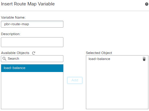
  • To insert policy object variables, choose Insert > Insert Policy Object > Object Type, selecting the appropriate type of object. Then, give the variable a name (which can be the same name as the associated policy object), select the object to associate with the variable, and click Save. For a detailed explanation of these types, see FlexConfig Policy Object Variables. For more detail on the procedure, see Add a Policy Object Variable to a FlexConfig Object.

  • To insert secret key variables, choose Insert > Secret Key and define the variable name and value. For more detail on the procedure, see Configure Secret Keys.

Note


You must use the Insert menu to create a new policy object or system variable. However, for subsequent uses of that variable, you must type it in, $ included. This is also true for system variables: the first time you use it, add it from the Insert menu. Then, type it out for subsequent uses. If you use the Insert menu more than once for a system variable, the system variable is added to the Variables list multiple times, and the FlexConfig will not validate, meaning you cannot save your changes. For processing variables (those not associated with a policy object or system variable), simply type in the variable. If you are adding a secret key, always use the Insert menu. Secret key variables do not show up in the Variables list.

Step 6

Choose the deployment frequency and type.

  • Deployment—Whether to deploy the commands in the object Once or Everytime. The only way to choose the right option is to test the results of deployment.

    Start by selecting Everytime. Then, after you attach the object to a FlexConfig policy, deploy the configuration. After a successful deployment, come back to the FlexConfig policy and preview the configuration for one of the assigned devices as described in Preview the FlexConfig Policy. If the section labeled ###CLI generated from managed features ### contains commands that clear or negate the commands in the object, and the ###Flex-config Appended CLI ### section contains the commands to reconfigure the feature, you know that Everytime is the right option.

    Even if you do not see negate commands, make some minor change to the device configuration, then run another deployment. If the deployment completes successfully, you can check the deployment transcript (see Verify the Deployed Configuration). If you see that the commands were issued again (even when they were already configured) without error, then you can keep Everytime.

    Change to Once only if the system does not first negate the commands in the object before issuing them again, or if the deployment results in errors that are specific to the command. In some cases, the system does not allow you to issue a command that is already configured, but this is the exception.

    Some additional tips:

    • If the FlexConfig object points to system-managed objects such as network or ACL objects, choose Everytime. Otherwise, updates to the objects might not get deployed.

    • Use Once if the only thing you do in the object is to clear a configuration. Then, remove the object from the FlexConfig policy after the next deployment.

  • Type—Select one of the following:

    • Append—(The default.) Commands in the object are put at the end of the configurations generated from the Firepower Management Center policies. You must use Append if you use policy object variables, which point to objects generated from managed objects. If commands generated for other policies overlap with those specified in the object, you should select this option so your commands are not overwritten. This is the safest option.

    • Prepend—Commands in the object are put at the beginning of the configurations generated from the Firepower Management Center policies. You would typically use prepend for commands that clear or negate a configuration.

Step 7

(Optional.) Click Validate above the object body to check the integrity of the script.

The object is always validated when you click Save. You cannot save an invalid object.

Step 8

Click Save.


What to do next

Add a Policy Object Variable to a FlexConfig Object

You can insert variables into a FlexConfig policy object that are associated with other types of policy object. When the FlexConfig is deployed to a device, these variables resolve to the names or content of the associated object.

Use the following procedure for the first use of a policy object variable in a FlexConfig object. If you need to refer to the object again, type in the variable (including the $ sign). To understand how to use these variables, see How to Process Variables.

Procedure

Step 1

Choose Insert > Insert Policy Object > Object Type, selecting the appropriate type of object.

Step 2

Enter a name for the variable, and optionally, a description.

The name must be unique within the context of the FlexConfig object. It cannot include spaces. You are allowed to use the exact same name as the object associated with the variable.

Step 3

Select the object to associate with the variable and click Add to move it to the Selected Object list.

You can associate a variable with a single object only.

Note


For text objects, you can select any of the predefined objects as needed. However, many of these objects have no default values. You must update the objects to add the required values either directly or as overrides for the device to which you will deploy the FlexConfig object. Trying to deploy a FlexConfig without updating these objects typically results in deployment errors.

Step 4

Click Save.

The variable appears in the Variables list at the bottom of the FlexConfig object editor.


Configure Secret Keys

A secret key is any single-string variable whose content you want to mask, such as passwords. The system provides special treatment for these variables to help you prevent the dissemination of sensitive information.

Secret key variables do not show up in the Variables list in the FlexConfig object.

Use the following procedure to create, insert, and otherwise manage secret key variables in a FlexConfig object. Unlike other types of variables, you can use the Insert command every time you need to insert a given secret key variable. With respect to processing, these variables behave like single-value text object variables; see Single Value Variables.


Note


Any data defined in a secret key variable is masked from users except when previewing a FlexConfig policy. In addition, if you export a FlexConfig policy, the content of any secret key variable is erased. When you import the policy, you will need to manually edit each secret key variable to enter the data.


Procedure

Step 1

While editing a FlexConfig Policy Object, choose Insert > Secret Key.

Step 2

In the Insert Secret Key dialog box, do any of the following:

  • To create a new key, click Add Secret Key, then fill in the following information and click Add.

    • Secret Key Name—The name of the variable. This name appears in the FlexConfig object prefixed with @.

    • Password, Confirm Password—The secret string, which is masked with asterisks as you type.

  • To insert a secret key variable in the FlexConfig object, select the check box for the variable.

  • To edit the value of a secret key variable, click Edit (edit icon) for the variable. Make your changes and click Add.

  • To delete a secret key variable, click Delete (delete icon) for the variable.

Step 3

Click Save.


Configure FlexConfig Text Objects

Use text objects in FlexConfig objects as the target of policy object variables. You can use variables to supply information that can be known only at runtime, or which can differ from device to device. During deployment, variables that point to text objects are replaced by the content of the text object.

Text objects contain free-form strings, which can be keywords, interface names, numbers, IP addresses, and so forth. The content depends on how you will use the information within a FlexConfig script.

Before creating or editing a text object, determine exactly what content you will need. This includes how you intend to process the object, which will help you decide between creating a single string or multiple string object. Read the following topics:

Procedure


Step 1

Choose Objects > Object Management.

Step 2

Choose FlexConfig > Text Object from the list of object types.

Step 3

Do one of the following:

  • Click Add Text Object to create a new object.

  • Click Edit (edit icon) to edit an existing object. You are allowed to edit the predefined text objects, which is required if you intended to use the predefined FlexConfig objects.

Step 4

Enter a Name and optionally, a description for the object.

Step 5

(New objects only.) Choose a Variable Type from the drop-down list:

  • Single—If the object should contain a single text string.
  • Multiple—If the object should contain a list of text strings.

You cannot change the variable type after you save the object.

Step 6

If the variable type is Multiple, use the up and down arrows to specify a Count.

Rows are added or removed from the object as you change the number.

Step 7

Add content to the object.

You can either click in the text box next to a variable number and type in a value, or you can set up device overrides for each device that will be assigned a FlexConfig object that uses the text object. You can also do both, in which case the values configured in the base object act as default values in cases where an override does not exist for a given device.

When editing predefined objects, it is a good practice to use device overrides, so that the system defaults remain in place for other users who might need to use the object in different FlexConfig policies. The approach you take depends on the requirements of your organization.

Tip


Some predefined objects require multiple values where each value serves a specific purpose. Read the description text carefully to determine the expected values in the object. In some cases, the instructions specify that you must use overrides instead of changing the base values. In the case of enableInspectProtocolList, you are prevented from entering protocols whose inspection is incompatible with Snort inspection.

If you decide to use device overrides, do the following.

  1. Select Allow Overrides.

  2. Expand the Overrides area (if necessary) and click Add.

    If an override already exists for the device, click edit for the override to change it.

  3. On Targets in the Add Object Override dialog box, select the device for which you are defining values and click Add to move it to the Selected Devices list.

  4. Click Override, adjust the Count as needed, then click in the variable fields and type in the values for the device.

  5. Click Add.

Step 8

Click Save.


What to do next

Configure the FlexConfig Policy

A FlexConfig policy contains two ordered lists of FlexConfig objects, one prepended list and one appended list. For an explanation of prepend/append, see Configure FlexConfig Objects.

FlexConfig policies are shared policies that you can assign to multiple devices.

Procedure


Step 1

Choose Devices > FlexConfig.

Step 2

Do one of the following:

  • Click New Policy to create a new FlexConfig Policy. You are prompted to enter a name. Optionally, select devices in the Available Devices list and click Add to Policy to assign devices. Click Save.

  • Click Edit (edit icon) to edit an existing Policy. You can change the name or description by clicking them in edit mode.

  • Click Copy (copy icon) to create a new policy with the same contents. You are prompted for a name. Device assignments are not retained for the copy.

  • Click delete to remove a policy you no longer need.

Step 3

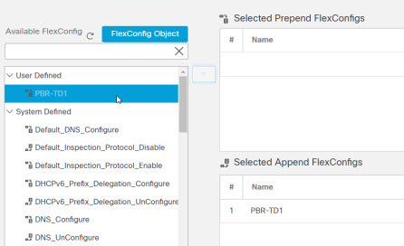
Select the FlexConfig objects required for the policy from the Available FlexConfig list and click > to add them to the policy.

Objects are automatically added to the prepended or appended list based on the deployment type specified in the FlexConfig object.

To remove a selected object, click Delete (delete icon) next to an object.

Step 4

For each selected object, click View (View button) next to the object to identify the variables used in the object.

Except for system variables, which start with SYS, you need to ensure that the objects associated with the variables are not empty. A blank or brackets with nothing between them, [ ], indicate an empty object. You will need to edit these objects before deploying the policy.

Note


If you use object overrides, those values will not show up in this view. Thus, an empty default value does not necessarily mean that you have not updated the object with the required values. Previewing the configuration will show whether the variables resolve correctly for a given device. See Preview the FlexConfig Policy.

Step 5

Click Save.


What to do next

Set Target Devices for a FlexConfig Policy

When you create a FlexConfig policy, you can select the devices that use the policy. You can subsequently change device assignments for the policy as described below.


Note


Normally, when you unassign a policy from a device, the system automatically removes the associated configuration upon the next deployment. However, because FlexConfig objects are scripts for deploying customized commands, simply unassigning a FlexConfig policy from a device does not remove the commands that were configuring by the FlexConfig objects. If your intention is to remove FlexConfig-generated commands from a device's configuration, see Remove Features Configured Using FlexConfig.


Procedure


Step 1

Choose Devices > FlexConfig and edit a FlexConfig policy.

Step 2

Click Policy Assignments.

Step 3

On Targeted Devices, build your target list:

  • Add—Choose one or more Available Devices, then click Add to Policy or drag and drop into the list of Selected Devices. You can assign the policy to devices, high availability pairs, and clustered devices.
  • Delete—Click Delete (delete icon) next to a single device, or select multiple devices, right-click, then choose Delete Selection.

Step 4

Click OK to save your selection.

Step 5

Click Save to save the FlexConfig policy.


What to do next

Preview the FlexConfig Policy

Preview a FlexConfig policy to see how the FlexConfig objects get translated into CLI commands. The preview shows the commands that will be generated for a selected device from the scripts and variables used in the FlexConfig objects. The variables are resolved based on the configuration for the device, so you get a clear idea of what will be deployed.

Use the preview to look for potential problems in the FlexConfig objects. Correct the objects until the preview shows the expected results.

You must preview the configuration separately for each device, because the variables can resolve differently based on the device configuration.

Procedure


Step 1

Choose Devices > FlexConfig and edit a FlexConfig policy.

Step 2

If there are any pending changes, click Save.

The preview shows results only for those FlexConfig objects that were in the most recently saved version of the policy. You must save the policy to see a preview of newly-added objects.

Step 3

Click Preview Config.

Step 4

Choose a device from the Select Device drop-down list.

The system retrieves information from the device and configured policies, and determines what CLI commands will be generated on the next deployment to the device. You can select the output and use Ctrl+C to copy it to the clipboard, where you can paste it into a text file for further analysis.

The preview includes the following sections:

  • Flex-config Prepended CLI—These are the commands generated by FlexConfigs that are prepended to the configuration.

  • CLI generated from managed features—These are commands generated for policies configured in Firepower Management Center. Commands are generated for new or changed policies since the last successful deployment to the device. These commands do not represent all commands needed to implement the assigned policies. No commands in this section are generated from FlexConfig objects.

  • Flex-config Appended CLI—These are the commands generated by FlexConfigs that are appended to the configuration.

Step 5

Click Close to close the preview dialog.


Verify the Deployed Configuration

After you deploy a FlexConfig policy to a device, verify that the deployment was successful and that the resulting configuration is what you expected. Also, verify that the device is performing as expected.

Procedure


Step 1

To verify that deployment was successful:

  1. Click System Status in the menu bar, which is unnamed between Deploy and System.

    The icon looks like one of the following, and it might include a number if there are errors:

    • Indicates No Warnings — Indicates no warnings or errors are present on the system.

    • Indicates One or More Warnings — Indicates one or more warnings and no errors are present on the system.

    • Indicates One or More Errors — Indicates one or more errors and any number of warnings are present on the system.

  2. On Deployments, verify that the deployment was successful.

  3. To see more detailed information, especially for failed deployments, click Show History.

  4. Select the deployment job in the list of jobs in the left column.

    Jobs are listed in reverse chronological order, with the most recent job at the top of the list.

  5. Click download in the Transcript column for the device in the right column.

    The deployment transcript includes commands sent to the device, and any responses returned from the device. These response can be informative messages or error messages. For failed deployments, look for messages that indicate errors with the commands that you sent through FlexConfig. These errors can help you correct the script in the FlexConfig object that is trying to configure the commands.

    Note


    There is no distinction made in the transcript between commands sent for managed features and those generated from FlexConfig policies.

    For example, the following sequence shows that Firepower Management Center (FMC) sent commands to configure GigabitEthernet0/0 with the logical name outside. The device responded that it automatically set the security level to 0. Firepower Threat Defense does not use the security level for anything. Messages relevant to FlexConfig are in the CLI Apply section of the transcript.

    
    ========= CLI APPLY =========
    
    FMC >> interface GigabitEthernet0/0
    FMC >>  nameif outside
    FTDv 192.168.0.152 >> [info] : INFO: Security level for "outside" set to 0 by default.


Step 2

Verify that the deployed configuration includes the expected commands.

You can do this by making an SSH connection to the device's management IP address. Use the show running-config command to view the configuration.

Alternatively, use the CLI tool within Firepower Management Center.

  1. Choose System > Health > Monitor and click the name of the device.

    You might need to click the open/close arrow in the Count column in the Status table to see any devices.

  2. Click Advanced Troubleshooting.

  3. Click Threat Defense CLI.

  4. Select show as the command, and type running-config as the parameter.

  5. Click Execute.

    The running configuration appears in the text box. You can select the configuration and press Ctrl+C, then paste it into a text file for later analysis.

Step 3

Verify that the device is performing as expected.

Use the show commands related to the feature to see detailed information and statistics. For example, if you enabled additional protocol inspections, the show service-policy command provides this information. The exact commands to use are feature-dependent and should be mentioned in the ASA configuration guide and command reference you used to learn how to configure the feature.

If commands that show statistics indicate that numbers are not changing (for example, hit counts, connection counts, and so forth), the configuration might be valid but not meaningful. If you know that traffic is going through the device that should show up in statistics, look for what is missing in your configuration. For example, NAT or access rules might be dropping or changing traffic before a feature can act on it.

You can use the show commands from an SSH session or through the Firepower Management Center CLI tool.

However, if the show command that you need to use is not available directly within the Firepower Threat Defense CLI, you will need make an SSH connection to the device to use the commands. From the CLI, enter the following command sequence to enter Privileged EXEC mode within the diagnostic CLI. From there, you should be able to enter these otherwise unsupported show commands.


> system support diagnostic-cli
Attaching to Diagnostic CLI ... Press 'Ctrl+a then d' to detach.
Type help or '?' for a list of available commands.
firepower> enable
Password: <press enter, do not enter a password>
firepower#


Remove Features Configured Using FlexConfig

If you decide you need to remove a set of configuration commands you configured using FlexConfig, you might need to manually remove that configuration. Unassigning the FlexConfig policy from a device might not remove all of the configuration.

To manually remove the configuration, you create new FlexConfig objects to clear or negate the configuration commands.

Before you begin

To determine if you need to manually remove some or all of the configuration generated by an object:

  1. Examine the configuration preview, as described in Preview the FlexConfig Policy. If the ###CLI generated from managed features ### section contains the clear or negate commands to remove all of the commands in the FlexConfig object, then you can simply remove the object from the FlexConfig policy, save, and redeploy.

  2. Remove the object from the FlexConfig policy, save the change, then preview the configuration again. If the ###CLI generated from managed features ### section still does not include the required clear or negate commands, you must follow this procedure to manually remove the configuration.

Procedure


Step 1

Choose Objects > Object Management and create the FlexConfig Objects to clear or negate the configuration commands.

If a feature has a clear command that can remove all configuration settings, then use that command. For example, the predefined Eigrp_Unconfigure_All object contains a single command that removes all EIGRP-related configuration commands:


clear configure router eigrp

If there is not a clear command for the feature, you need to use the no form of each command you want to remove. For example, the predefined Sysopt_basic_negate object removes the commands configured through the predefined Sysopt_basic object.


no sysopt traffic detailed-statistics

no sysopt connection timewait

You would typically configure a FlexConfig object that removes configurations as a prepended, deploy once object.

Step 2

Choose Devices > FlexConfig and create a new FlexConfig policy or edit the existing policy.

If you want to preserve the FlexConfig policy that deploys the configuration commands, create a new policy specifically for negating the commands, and assign the devices to the policy. Then, add the new FlexConfig objects to the policy.

If you want to completely remove the FlexConfig configuration objects from all devices, you can simply delete those commands from the existing FlexConfig policy and replace them with the objects that negate the configuration.

Step 3

Click Save to save the FlexConfig policy.

Step 4

Click Preview Config and verify that the clear and negation commands are generating correctly.

Step 5

Choose Deploy > Deployment in the menu bar, select the device, and click Deploy.

Wait for deployment to complete.

Step 6

Verify that the commands were removed.

View the running configuration on the device to confirm that the commands are removed. For more detailed information, see Verify the Deployed Configuration.

Step 7

While editing the FlexConfig policy, click Policy Assignments and remove the device. Optionally, remove the FlexConfig Objects from the policy.

Assuming that the FlexConfig policy simply removes the unwanted configuration commands, there is no need to keep the policy assigned to the device after the removal is complete.

However, if the FlexConfig policy retains options that you still want configured on the device, remove the negation objects from the policy. They are no longer needed.


Convert from FlexConfig to Managed Feature

Each software release adds managed features to the product, that is, features that you configure directly through policies that are controlled outside of FlexConfig. This can deprecate FlexConfig commands that you are currently using; your configurations are not automatically converted. After the upgrade, you cannot assign or create FlexConfig objects using the newly deprecated commands. After upgrading software, examine your FlexConfig policies and objects.

When a feature you configured using FlexConfig starts to be supported as a managed feature, you must convert from using FlexConfig to using the managed feature. In most cases, your existing FlexConfig configurations continue to work post-upgrade and you can still deploy. However, in some cases, using deprecated commands can cause deployment issues. Configuring a feature in both the GUI and FlexConfig is not supported.

Procedure


Step 1

Remove the FlexConfig, as explained in Remove Features Configured Using FlexConfig.

Step 2

Configure the settings in the newly supported managed feature.

The release notes have a list of new features for the release.


Examples for FlexConfig

Following are some examples of using FlexConfig.

How to Configure Precision Time Protocol (ISA 3000)

The Precision Time Protocol (PTP) is a time-synchronization protocol developed to synchronize the clocks of various devices in a packet-based network. These device clocks are generally of varying precision and stability. The protocol is designed specifically for industrial, networked measurement and control systems, and is optimal for use in distributed systems because it requires minimal bandwidth and little processing overhead.

A PTP system is a distributed, networked system consisting of a combination of PTP and non-PTP devices. PTP devices include ordinary clocks, boundary clocks and transparent clocks. Non-PTP devices include network switches, routers and other infrastructure devices.

You can configure the FTD device to be a transparent clock. The FTD device does not synchronize its clock with the PTP clocks. The FTD device will use the PTP default profile, as defined on the PTP clocks.

When you configure the PTP devices, you define a domain number for the devices that are meant to function together. Thus, you can configure multiple PTP domains, and then configure each non-PTP device to use the PTP clocks for one specific domain.

Before you begin

Determine the domain number configured on the PTP clocks that the device should use. This example assumes the PTP domain number is 10. Also, determine the interfaces through which the system can reach the PTP clocks in the domain.

Following are guidelines for configuring PTP:

  • This feature is only available on the Cisco ISA 3000 appliance.

  • Cisco PTP supports multicast PTP messages only.

  • PTP is available only for IPv4 networks, not for IPv6 networks.

  • PTP configuration is supported on physical Ethernet data interfaces, whether stand-alone or bridge group members. It is not supported on the management interface, subinterfaces, EtherChannels, Bridge Virtual Interfaces (BVI), or any other virtual interfaces.

  • PTP flows on VLAN subinterfaces are supported, assuming the appropriate PTP configuration is present on the parent interface.

  • You must ensure that PTP packets are allowed to flow through the device. PTP traffic is identified by UDP destination ports 319 and 320, and destination IP address 224.0.1.129, so any access control rule that allows this traffic should work.

  • In Routed firewall mode, you must enable Multicast routing for PTP multicast groups. In addition, if an interface on which you enable PTP is not in a bridge group, you must configure the interface to join the IGMP multicast group 224.0.1.129. If the physical interface is a bridge group member, you do not configure it to join the IGMP multicast group.

Procedure


Step 1

(Routed mode only.) Enable Multicast routing, and configure the IGMP group for the interfaces.

In Routed mode, you must enable Multicast routing. In addition, for stand-alone physical interfaces, that is, those that are not bridge group members, you must also configure the interface to join the 224.0.1.129 IGMP group. You cannot configure bridge group members to join an IGMP group, but PTP configuration on bridge group members will work without the IGMP join.

Perform this procedure for each device on which you will configure PTP.

Note


Write down the hardware names of each PTP-clock-facing interface on each device, for example, GigabitEthernet1/1.

  1. Choose Devices > Device Management, and edit the device.

  2. Click Routing.

  3. Select Multicast Routing > IGMP.

  4. Select the Enable Multicast Routing check box.

  5. Click Join Group.

  6. Click Add, and in the Add IGMP Join Group Parameters dialog box, configure the following options and click OK.

    • Interface—Select the PTP-clock-facing stand-alone interface.

    • Join Group—Click + to add a new network object. Create a Host object with the address 224.0.1.129. When configuring additional interfaces, simply select this object.

    Repeat this step for each PTP-clock-facing stand-alone interface on the device.

  7. Click Save on the Routing page.

Step 2

Create the FlexConfig object to enable PTP globally and on the interface.

The following procedure assumes that the PTP-clock-facing interface is the same on every device you are configuring. If you have used different interfaces on different devices, you need to create separate objects for each distinct combination. For example, if you use GigabitEthernet1/1 on devices A and B, GigabitEthernet1/2 on devices C and D, and both GigabitEthernet1/1 and 1/2 on devices E and F, you need 3 separate FlexConfig objects, and subsequently, 3 separate FlexConfig policies (explained in the next step).

  1. Choose Objects > Object Management.

  2. Choose FlexConfig > FlexConfig Object from the table of contents.

  3. Click Add FlexConfig Object, configure the following properties, and click Save.

    • Name—The object name. For example, Enable_PTP.

    • Deployment—Select Everytime. You want this configuration to be sent in every deployment to ensure it remains configured.

    • Type—Keep the default, Append. The commands are sent to the device after the commands for directly-supported features. This ensures that any other changes you make to interface configuration are configured before these commands.

    • Object body—In the object body, type the commands needed to configure PTP globally and on each PTP-clock-facing interface. For example, the commands needed for the global configuration for PTP domain 10 and the interface configuration on GigabitEthernet1/1 are:

      
      ptp mode e2etransparent
      ptp domain 10
      interface gigabitethernet1/1
       ptp enable

    The object body should look similar to the following:

Step 3

Create the FlexConfig policy and assign it to the devices.

If you created multiple FlexConfig objects for different combinations of PTP-clock-facing interfaces, you need to create separate FlexConfig policies for each object, and assign those policies to the correct devices based on the interfaces you need to configure. Repeat the following procedure for each group of devices.

  1. Choose Devices > FlexConfig.

  2. Either click New Policy, or if an existing FlexConfig policy should be assigned to (or is already assigned to) the target devices, simply edit that policy.

    When creating a new policy, assign the target devices to the policy in the dialog box where you name the policy.

  3. Select the PTP FlexConfig object in the User Defined folder in the table of contents and click > to add it to the policy.

    The object should be added to the Selected Appended FlexConfigs list.

  4. Click Save.

  5. If you have not yet assigned all the targeted devices to the policy, click the Policy Assignments link below Save and make the assignments now.

  6. Click Preview Config, and in the Preview dialog box, select one of the assigned devices.

    The system generates a preview of the configuration CLI that will be sent to the device. Verify that the commands generated from the PTP FlexConfig object look correct. These will be shown at the end of the preview. Note that you will also see commands generated from other changes you have made to managed features. For the PTP commands, you should see something similar to the following:

    
    ###Flex-config Appended CLI ###
    ptp mode e2etransparent
    ptp domain 10
    interface gigabitethernet1/1
     ptp enable
    

Step 4

Deploy your changes.

Because you assigned a FlexConfig policy to the devices, you will always get a deployment warning, which is meant to caution you about the use of FlexConfig. Click Proceed to continue with the deployment.

After the deployment completes, you can check the deployment history and view the transcript for the deployment. This is especially valuable if the deployment fails. See Verify the Deployed Configuration.

Step 5

Verify the PTP configuration on each device.

From an SSH or Console session into each device, verify the PTP settings:


> show ptp clock
 PTP CLOCK INFO
  PTP Device Type: End to End Transparent Clock
  Operation mode: One Step
  Clock Identity: 34:62:88:FF:FE:1:73:81
  Clock Domain: 10
  Number of PTP ports: 4
> show ptp port
 PTP PORT DATASET: GigabitEthernet1/1
  Port identity: Clock Identity: 34:62:88:FF:FE:1:73:81
  Port identity: Port Number: 1
  PTP version: 2
  Port state: Enabled

 PTP PORT DATASET: GigabitEthernet1/2
  Port identity: Clock Identity: 34:62:88:FF:FE:1:73:81
  Port identity: Port Number: 2
  PTP version: 2
  Port state: Disabled

 PTP PORT DATASET: GigabitEthernet1/3
  Port identity: Clock Identity: 34:62:88:FF:FE:1:73:81
  Port identity: Port Number: 3
  PTP version: 2
  Port state: Disabled

 PTP PORT DATASET: GigabitEthernet1/4
  Port identity: Clock Identity: 34:62:88:FF:FE:1:73:81
  Port identity: Port Number: 4
  PTP version: 2
  Port state: Disabled

How to Configure Automatic Hardware Bypass for Power Failure (ISA 3000)

You can enable hardware bypass so that traffic continues to flow between an interface pair during a power outage. Supported interface pairs are copper interfaces GigabitEthernet 1/1 and 1/2; and GigabitEthernet 1/3 and 1/4. If you have a fiber Ethernet model, only the copper Ethernet pair (GigabitEthernet 1/1 and 1/2) supports hardware bypass.

When hardware bypass is active, traffic passes between these interface pairs at layer 1. The FTD CLI will see the interfaces as being down. No firewall functions are in place, so make sure you understand the risks of allowing traffic to pass through the device.

In CLI Console or an SSH session, use the show hardware-bypass command to monitor the operational status.

Before you begin

For hardware bypass to work:

  • You must place the interface pairs in the same bridge group.

  • You must attach the interfaces to access ports on the switch. Do not attach them to trunk ports.

We recommend that you disable TCP sequence number randomization globally using the Threat Defense Service Policy attached to the access control policy assigned to the device. By default, the ISA 3000 rewrites the initial sequence number (ISN) of TCP connections passing through it to a random number. When hardware bypass is activated, the ISA 3000 is no longer in the data path and does not translate the sequence numbers. The receiving client receives an unexpected sequence number and drops the connection, so the TCP session needs to be re-established. Even with TCP sequence number randomization disabled, some TCP connections will have to be re-established because of the link that is temporarily down during the switchover.

Procedure


Step 1

Create the FlexConfig object to enable automatic bypass.

  1. Choose Objects > Object Management.

  2. Choose FlexConfig > FlexConfig Object from the table of contents.

  3. Click Add FlexConfig Object, configure the following properties, and click Save.

    • Name—The object name. For example, Enable_HW-Bypass.

    • Deployment—Select Everytime. You want this configuration to be sent in every deployment to ensure it remains configured.

    • Type—Keep the default, Append. The commands are sent to the device after the commands for directly-supported features.

    • Object body—In the object body, type the commands needed to enable automatic hardware bypass. For example, the commands needed for both possible interface pairs:

      
      hardware-bypass GigabitEthernet 1/1-1/2
      hardware-bypass GigabitEthernet 1/3-1/4
      

    The object body should look similar to the following:


    FlexConfig object for enabling hardware bypass on ISA 3000 devices.

Step 2

Create the FlexConfig policy and assign it to the devices.

  1. Choose Devices > FlexConfig.

  2. Either click New Policy, or if an existing FlexConfig policy should be assigned to (or is already assigned to) the target devices, simply edit that policy.

    When creating a new policy, assign the target devices to the policy in the dialog box where you name the policy.

  3. Select the hardware bypass FlexConfig object in the User Defined folder in the table of contents and click > to add it to the policy.

    The object should be added to the Selected Appended FlexConfigs list.


    FlexConfig policy, enable hardware bypass object in the selected objects list.

  4. Click Save.

  5. If you have not yet assigned all the targeted devices to the policy, click the Policy Assignments link below Save and make the assignments now.

  6. Click Preview Config, and in the Preview dialog box, select one of the assigned devices.

    The system generates a preview of the configuration CLI that will be sent to the device. Verify that the commands generated from the hardware bypass FlexConfig object look correct. These will be shown at the end of the preview. Note that you will also see commands generated from other changes you have made to managed features. For the hardware bypass commands, you should see something similar to the following:

    
    ###Flex-config Appended CLI ###
    hardware-bypass GigabitEthernet 1/1-1/2
    hardware-bypass GigabitEthernet 1/3-1/4
    

Step 3

Deploy your changes.

Because you assigned a FlexConfig policy to the devices, you will always get a deployment warning, which is meant to caution you about the use of FlexConfig. Click Proceed to continue with the deployment.

After the deployment completes, you can check the deployment history and view the transcript for the deployment. This is especially valuable if the deployment fails. See Verify the Deployed Configuration.


What to do next

If you want to manually invoke hardware bypass or manually turn it off, you need to create two FlexConfig objects:

  • One that manually starts bypass, which would contain one or both of the following commands, depending on whether you want to invoke bypass for both pairs:

    
    hardware-bypass manual GigabitEthernet 1/1-1/2
    hardware-bypass manual GigabitEthernet 1/3-1/4
    
  • One that manually turns off bypass, which would contain one or both of the following commands:

    
    no hardware-bypass manual GigabitEthernet 1/1-1/2
    no hardware-bypass manual GigabitEthernet 1/3-1/4
    

You would then need to add one or the other object to the FlexConfig policy, and deploy changes, to either turn bypass on or off. You would also need to immediately remove the object from the FlexConfig policy after deployment. If you manually invoke bypass, you would then need to repeat the process to turn it off again. Thus, using this manual method requires frequent and careful editing of the FlexConfig policy and additional deployments.

How to Configure Policy Based Routing

You can implement policy-based routing (PBR) features using FlexConfig. For example, the following graphic shows how to load balance traffic between networks based on source IP address. In this case, we will assume that the 10.1.0.0/16 network generates high priority traffic, which should go over the higher bandwidth link to ISP-A, and 10.2.0.0/16 is lower priority and should go over the slower, lower bandwidth link to ISP-B.


Policy based routing load balancing network diagram.

Before you begin

This procedure assumes that you have already configured the interfaces as follows:

  • GigabitEthernet0/0.

    • Interface name: inside

    • IP address: 10.1.1.1/24

    • Note that other routers in the network use this interface as the gateway for routes for the 10.1.0.0/16 and 10.2.0.0/16 address spaces.

  • GigabitEthernet0/1.

    • Interface name: outside-1

    • IP address: 192.168.6.5/24

  • GigabitEthernet0/2.

    • Interface name: outside-2

    • IP address: 172.16.7.6/24

Procedure


Step 1

Create the extended ACL objects to match traffic from the 10.1.0.0/16 and 10.2.0.0/16 address spaces. You must create separate ACLs, because you will apply different actions to the traffic in the route map.

  1. Choose Objects > Object Management.

  2. Select Access List > Extended from the table of contents. You must configure an extended access list to specify the traffic source addresses.

  3. Click the Add Extended Access List button.

  4. Enter a name for the access list, such as high-priority.

  5. Click the Add button, and create the rule for the high-priority address space. The key characteristics are:

    • ActionAllow.

    • Source Networks—Enter 10.1.0.0/16 in the edit box below the list and click Add. Alternatively, you can define a network object for this network address.

  6. Click Add at the bottom of the dialog box. This adds the rule to the access list.


    High-priority extended access list.

  7. Click Save.

  8. Repeat the process to create a second access list with the following attributes:

  • Namelow-priority.

  • ActionAllow.

  • Source Networks—Enter 10.2.0.0/16 in the edit box below the list and click Add. Alternatively, you can define a network object for this network address.


Low-priority access list.

Step 2

Create the route map that defines the next hop addresses for these address spaces.

  1. While still on the objects page, click Route Map in the table of contents.

  2. Click the Add Route Map button.

  3. Enter a name for the object, such as load-balance.

  4. Click Add and create a rule for high-priority traffic with the following attributes:

    • Sequence No.10.

    • RedistributionAllow.

    • Match Clauses > IPv4 > Address—Select the Access List radio button, then Available Access Lists > Extended, and move the high-priority ACL to the selected list.


      Match clause for the load balancing route map.

    • Set Clauses > BGP Clauses > Others—In IPv4 Settings > Next Hop, select Specific IP, then enter the gateway for ISP-A, 192.168.6.6 into the Specific IP edit box.


    Set clause for the load balancing route map.

  5. Click Add to add the rule to the route map.

  6. Click Add and create a rule for low-priority traffic with the following attributes:

    • Sequence No.20.

    • RedistributionAllow.

    • Match Clauses > IPv4 > Address—Select the Access List radio button, then Available Access Lists > Extended, and move the low-priority ACL to the selected list.

    • Set Clauses > BGP Clauses > Others—In IPv4 Settings > Next Hop, select Specific IP, then enter the gateway for ISP-B, 172.16.7.7 into the Specific IP edit box.

  7. Click Add to add the rule to the route map.


    Load balancing route map.

  8. Click Save.

Step 3

Create the FlexConfig object that enables PBR on the inside interface using the route map.

  1. While still on the objects page, click FlexConfig > FlexConfig Object in the table of contents.

  2. Find the Policy_Based_Routing object, then click the Copy (copy icon).

    This is a system-defined object, but it is not usable until you edit it. It does not point to a text object that you can simply update with the name of your route map. You must always create a custom object for this system-defined object.

  3. When you click the copy icon, the system opens a dialog box with the new object, with the default name Policy_Based_Routing_Copy. Make these basic changes:

    • Name—Enter a meaningful name. For example, if you are configuring PBR for device FTD1, perhaps PBR_FTD1.

    • Description—Delete the description or make it meaningful for your purposes.

    • Deployment—Keep Once.

    • Type—Keep Append.

  4. The body of the object has the following lines.

    
    interface GigabitEthernet0/0
        policy-route route-map $r-map-object
    

    Note that the “interface GigabitEthernet0/0” line already is set to configure the correct interface for this example. If you were to apply PBR to a different interface, you would need to correct the interface hardware name.

    The $r-map-object string actually is not a real variable, and it points to nothing. You need to replace this string.

  5. Delete the $r-map-object string, and leave your cursor on the “policy-route route-map” line, one space after route-map.

  6. Select Insert > Insert Policy Object > Route Map.

  7. In the Route Map Variable dialog box, configure the following:

    • Variable Name—Any name will do, such as pbr-route-map.

    • Selected Object—Move the load-balance route map object from the available list to the selected list.


    Route map variable in the FlexConfig object.

  8. Click Save in the Route Map Variable dialog box.

    The FlexConfig object should now look like the following, where your variable is now in the variables list at the bottom of the dialog box.


    Completed FlexConfig object.

  9. Click Save.

Step 4

Add the FlexConfig object to the FlexConfig policy that is assigned to the device.

  1. Choose Devices > FlexConfig.

  2. Assuming you do not already have a FlexConfig policy assigned to this device, click New Policy, give the policy a name and select the FTD1 device to assign the policy to it, then click Save.

  3. Find the object under the User Defined folder in the available objects list, then click > to add it to the selected objects list.


    Adding the FlexConfig object to the FlexConfig policy.

  4. Click Save to save the policy.

  5. Click Preview Config, then in the preview dialog box, select the FTD1 device.

    The preview includes CLI generated from both the FlexConfig objects and the parts of the FMC-managed configuration that are implemented using configuration commands. These are separated into sections. The commands that will be configured based on what we have done in this example are the following. You can verify you are getting the expected results using this preview.

    
    ###Flex-config Prepended CLI ###
    
    ###CLI generated from managed features ###
    configure session OBJECT
    object-group service ProxySG_ExtendedACL_4294969626
     service-object ip
    object-group service ProxySG_ExtendedACL_4294969648
     service-object ip
    commit noconfirm revert-save
    configure session FMC_SESSION_1
    access-list high-priority extended permit object-group 
          ProxySG_ExtendedACL_4294969626 10.1.0.0 255.255.0.0 any
    access-list low-priority extended permit object-group 
          ProxySG_ExtendedACL_4294969648 10.2.0.0 255.255.0.0 any
    commit noconfirm revert-save
    route-map load-balance permit 10
     match ip address high-priority
     set ip next-hop 192.168.6.6
    route-map load-balance permit 20
     match ip address low-priority
     set ip next-hop 172.16.7.7
    
    
    ###Flex-config Appended CLI ###
    interface GigabitEthernet0/0
        policy-route route-map load-balance
    
  6. Click Close to shut the preview dialog box.


What to do next

You can now deploy the configuration to the device.

History for FlexConfig

Feature

Version

Description

FlexConfig.

6.2

The FlexConfig feature allows you use the Firepower Management Center to deploy ASA CLI template-based functionality to Firepower Threat Defense devices. This feature allows you to enable some of the most valuable ASA functions that are not currently available on Firepower Threat Defense devices. This functionality is structured as templates and objects that work together in a policy. The default templates are officially supported by Cisco TAC.

New screen: Devices > FlexConfig. Also, under Objects > Object Management, FlexConfig > FlexConfig Objects and FlexConfig > Text Object.

Supported platforms: Firepower Threat Defense

FlexConfig Updates

6.2(1)

6.2(2)

As per the Government Certification requirements, all sensitive information like password, shared keys in system-provided or user-defined FlexConfig object should be masked using secret key variables. After you update the Firepower Management Center to these releases, all sensitive information in FlexConfig Objects are converted to secret key variable format.

In addition, the following new FlexConfig templates are added:

  • Default_DNS_Configure template allows you to the default DNS group, which is used to resolve hostnames for commands or features that resolve names through the data interfaces.

  • TCP Embryonic connection limit and timeout configuration template allows you to configure embryonic connection limits/timeout CLIs to protect from SYN Flood DoSAttack.

  • Turn on threat detection configure and clear templates allow you to configure threat detection statistics for attacks intercepted by TCP Intercept.

  • IPV6 router header inspection template allows you to configure of IPV6 inspection header for selectively allow/block certain headers with different types (e.g. allowing RH Type 2,mobile).

  • DHCPv6 prefix delegation template allows you to configure one outside (PD client) and one inside interface (recipient of delegated prefix) for IPv6 prefix delegation.

Supported platforms: Firepower Threat Defense

Deprecated FlexConfig objects.

6.3

Several features that in previous releases you configured using FlexConfig are now directly supported in Firepower Management Center. You need to remove these FlexConfig objects if you are using them, and convert your configuration to use the new objects. Following are the deprecated FlexConfig objects and text objects.

  • Default_DNS_Configure, including the defaultDNSNameServerList and defaultDNSParameters text objects. Now, please configure DNS for the data interfaces using the Platform Settings policy.

  • TCP_Embryonic_Conn_Limit, and the tcp_conn_misc and tcp_conn_limit text objects. Configure these features in the Firepower Threat Defense Service Policy, which you can find on the Advanced tab of the access control policy assigned to the device.

  • TCP_Embryonic_Conn_Timeout, and the tcp_conn_misc and tcp_conn_timeout text objects. Configure these features in the Firepower Threat Defense Service Policy.

Supported platforms: Firepower Threat Defense

Precision Time Protocol (PTP) configuration for ISA 3000 devices.

6.5

You can use FlexConfig to configure the Precision Time Protocol (PTP) on ISA 3000 devices. PTP is a time-synchronization protocol developed to synchronize the clocks of various devices in a packet-based network. The protocol is designed specifically for industrial, networked measurement and control systems.

We now allow you to include the ptp (interface mode) command, and the global commands ptp mode e2etransparent and ptp domain , in FlexConfig objects.

New/Modified commands: show ptp .

Supported platforms: Firepower Threat Defense