Site-to-Site VPN

A virtual private network (VPN) is a network connection that establishes a secure tunnel between remote peers using a public source, such as the Internet or other network. VPNs use tunnels to encapsulate data packets within normal IP packets for forwarding over IP-based networks. They use encryption to ensure privacy and authentication to ensure the integrity of data.

VPN Basics

Tunneling makes it possible to use a public TCP/IP network, such as the Internet, to create secure connections between remote users and private corporate networks. Each secure connection is called a tunnel.

IPsec-based VPN technologies use the Internet Security Association and Key Management Protocol (ISAKMP, or IKE) and IPsec tunneling standards to build and manage tunnels. ISAKMP and IPsec accomplish the following:

  • Negotiate tunnel parameters.

  • Establish tunnels.

  • Authenticate users and data.

  • Manage security keys.

  • Encrypt and decrypt data.

  • Manage data transfer across the tunnel.

  • Manage data transfer inbound and outbound as a tunnel endpoint or router.

A device in a VPN functions as a bidirectional tunnel endpoint. It can receive plain packets from the private network, encapsulate them, create a tunnel, and send them to the other end of the tunnel where they are unencapsulated and sent to their final destination. It can also receive encapsulated packets from the public network, unencapsulate them, and send them to their final destination on the private network.

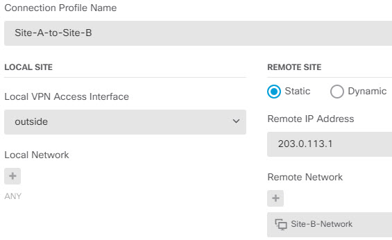
After the site-to-site VPN connection is established, the hosts behind the local gateway can connect to the hosts behind the remote gateway through the secure VPN tunnel. A connection consists of the IP addresses and hostnames of the two gateways, the subnets behind them, and the method the two gateways use to authenticate to each other.

Internet Key Exchange (IKE)

Internet Key Exchange (IKE) is a key management protocol that is used to authenticate IPsec peers, negotiate and distribute IPsec encryption keys, and to automatically establish IPsec security associations (SAs).

The IKE negotiation comprises two phases. Phase 1 negotiates a security association between two IKE peers, which enables the peers to communicate securely in Phase 2. During Phase 2 negotiation, IKE establishes SAs for other applications, such as IPsec. Both phases use proposals when they negotiate a connection.

An IKE policy is a set of algorithms that two peers use to secure the IKE negotiation between them. IKE negotiation begins by each peer agreeing on a common (shared) IKE policy. This policy states which security parameters protect subsequent IKE negotiations. For IKE version 1 (IKEv1), IKE policies contain a single set of algorithms and a modulus group. Unlike IKEv1, in an IKEv2 policy, you can select multiple algorithms and modulus groups from which peers can choose during the Phase 1 negotiation. It is possible to create a single IKE policy, although you might want different policies to give higher priority to your most desired options. For site-to-site VPNs, you can create a single IKE policy.

To define an IKE policy, specify:

  • A unique priority (1 to 65,543, with 1 the highest priority).

  • An encryption method for the IKE negotiation, to protect the data and ensure privacy.

  • A Hashed Message Authentication Codes (HMAC) method (called integrity algorithm in IKEv2) to ensure the identity of the sender, and to ensure that the message has not been modified in transit.

  • For IKEv2, a separate pseudorandom function (PRF) used as the algorithm to derive keying material and hashing operations required for the IKEv2 tunnel encryption. The options are the same as those used for the hash algorithm.

  • A Diffie-Hellman group to determine the strength of the encryption-key-determination algorithm. The device uses this algorithm to derive the encryption and hash keys.

  • An authentication method, to ensure the identity of the peers.

  • A limit to the time the device uses an encryption key before replacing it.

When IKE negotiation begins, the peer that starts the negotiation sends all of its enabled policies to the remote peer, and the remote peer searches for a match with its own policies, in priority order. A match between IKE policies exists if they have the same encryption, hash (integrity and PRF for IKEv2), authentication, and Diffie-Hellman values, and an SA lifetime less than or equal to the lifetime in the policy sent. If the lifetimes are not identical, the shorter lifetime, obtained from the remote peer, applies. By default, a simple IKE policy that uses DES is the only enabled policy. You can enable other IKE policies at higher priorities to negotiate stronger encryption standards, but the DES policy should ensure a successful negotiation.

How Secure Should a VPN Connection Be?

Because a VPN tunnel typically traverses a public network, most likely the Internet, you need to encrypt the connection to protect the traffic. You define the encryption and other security techniques to apply using IKE polices and IPsec proposals.

If your device license allows you to apply strong encryption, there is a wide range of encryption and hash algorithms, and Diffie-Hellman groups, from which to choose. However, as a general rule, the stronger the encryption that you apply to the tunnel, the worse the system performance. Find a balance between security and performance that provides sufficient protection without compromising efficiency.

We cannot provide specific guidance on which options to choose. If you operate within a larger corporation or other organization, there might already be defined standards that you need to meet. If not, take the time to research the options.

The following topics explain the available options.

Deciding Which Encryption Algorithm to Use

When deciding which encryption algorithms to use for the IKE policy or IPsec proposal, your choice is limited to algorithms supported by the devices in the VPN.

For IKEv2, you can configure multiple encryption algorithms. The system orders the settings from the most secure to the least secure and negotiates with the peer using that order. For IKEv1, you can select a single option only.

For IPsec proposals, the algorithm is used by the Encapsulating Security Protocol (ESP), which provides authentication, encryption, and anti-replay services. ESP is IP protocol type 50. In IKEv1 IPsec proposals, the algorithm name is prefixed with ESP-.

If your device license qualifies for strong encryption, you can choose from the following encryption algorithms. If you are not qualified for strong encryption, you can select DES only.

  • AES-GCM—(IKEv2 only.) Advanced Encryption Standard in Galois/Counter Mode is a block cipher mode of operation providing confidentiality and data-origin authentication, and provides greater security than AES. AES-GCM offers three different key strengths: 128-, 192-, and 256-bit keys. A longer key provides higher security but a reduction in performance. GCM is a mode of AES that is required to support NSA Suite B. NSA Suite B is a set of cryptographic algorithms that devices must support to meet federal standards for cryptographic strength. .

  • AES-GMAC—(IKEv2 IPsec proposals only.) Advanced Encryption Standard Galois Message Authentication Code is a block cipher mode of operation providing only data-origin authentication. It is a variant of AES-GCM that allows data authentication without encrypting the data. AES-GMAC offers three different key strengths: 128-, 192-, and 256-bit keys.

  • AES—Advanced Encryption Standard is a symmetric cipher algorithm that provides greater security than DES and is computationally more efficient than 3DES. AES offers three different key strengths: 128-, 192-, and 256-bit keys. A longer key provides higher security but a reduction in performance.

  • 3DES—Triple DES, which encrypts three times using 56-bit keys, is more secure than DES because it processes each block of data three times with a different key. However, it uses more system resources and is slower than DES.

  • DES—Data Encryption Standard, which encrypts using 56-bit keys, is a symmetric secret-key block algorithm. If your license account does not meet the requirements for export controls, this is your only option. It is faster than 3DES and uses less system resources, but it is also less secure. If you do not need strong data confidentiality, and if system resources or speed is a concern, choose DES.

  • Null, ESP-Null—Do not use. A null encryption algorithm provides authentication without encryption. This is not supported on most platforms.

Deciding Which Hash Algorithms to Use

In IKE policies, the hash algorithm creates a message digest, which is used to ensure message integrity. In IKEv2, the hash algorithm is separated into two options, one for the integrity algorithm, and one for the pseudo-random function (PRF).

In IPsec proposals, the hash algorithm is used by the Encapsulating Security Protocol (ESP) for authentication. In IKEv2 IPsec Proposals, this is called the integrity hash. In IKEv1 IPsec proposals, the algorithm name is prefixed with ESP-, and there is also an -HMAC suffix (which stands for “hash method authentication code”).

For IKEv2, you can configure multiple hash algorithms. The system orders the settings from the most secure to the least secure and negotiates with the peer using that order. For IKEv1, you can select a single option only.

You can choose from the following hash algorithms.

  • SHA (Secure Hash Algorithm)—Standard SHA (SHA1) produces a 160-bit digest. SHA is more resistant to brute-force attacks than MD5. However, it is also more resource intensive than MD5. For implementations that require the highest level of security, use the SHA hash algorithm.

    The following SHA-2 options, which are even more secure, are available for IKEv2 configurations. Choose one of these if you want to implement the NSA Suite B cryptography specification.

    • SHA256—Specifies the Secure Hash Algorithm SHA 2 with the 256-bit digest.

    • SHA384—Specifies the Secure Hash Algorithm SHA 2 with the 384-bit digest.

    • SHA512—Specifies the Secure Hash Algorithm SHA 2 with the 512-bit digest.

  • MD5 (Message Digest 5)—Produces a 128-bit digest. MD5 uses less processing time for an overall faster performance than SHA, but it is considered to be weaker than SHA.

  • Null or None (NULL, ESP-NONE)—(IPsec Proposals only.) A null Hash Algorithm; this is typically used for testing purposes only. However, you should choose the null integrity algorithm if you select one of the AES-GCM/GMAC options as the encryption algorithm. Even if you choose a non-null option, the integrity hash is ignored for these encryption standards.

Deciding Which Diffie-Hellman Modulus Group to Use

You can use the following Diffie-Hellman key derivation algorithms to generate IPsec security association (SA) keys. Each group has a different size modulus. A larger modulus provides higher security, but requires more processing time. You must have a matching modulus group on both peers.

If you select AES encryption, to support the large key sizes required by AES, you should use Diffie-Hellman (DH) Group 5 or higher. IKEv1 policies do not support all of the groups listed below.

To implement the NSA Suite B cryptography specification, use IKEv2 and select one of the elliptic curve Diffie-Hellman (ECDH) options: 19, 20, or 21. Elliptic curve options and groups that use 2048-bit modulus are less exposed to attacks such as Logjam.

For IKEv2, you can configure multiple groups. The system orders the settings from the most secure to the least secure and negotiates with the peer using that order. For IKEv1, you can select a single option only.

  • 2—Diffie-Hellman Group 2: 1024-bit modular exponential (MODP) group. This option is no longer considered good protection.

  • 5—Diffie-Hellman Group 5: 1536-bit MODP group. Formerly considered good protection for 128-bit keys, this option is no longer considered good protection.

  • 14—Diffie-Hellman Group 14: 2048-bit modular exponential (MODP) group. Considered good protection for 192-bit keys.

  • 15—Diffie-Hellman Group 15: 3072-bit MODP group.

  • 16—Diffie-Hellman Group 16: 4096-bit MODP group.

  • 19—Diffie-Hellman Group 19: National Institute of Standards and Technology (NIST) 256-bit elliptic curve modulo a prime (ECP) group.

  • 20—Diffie-Hellman Group 20: NIST 384-bit ECP group.

  • 21—Diffie-Hellman Group 21: NIST 521-bit ECP group.

  • 24—Diffie-Hellman Group 24: 2048-bit MODP group with 256-bit prime order subgroup. This option is no longer recommended.

Deciding Which Authentication Method to Use

You can use the following methods to authenticate the peers in a site-to-site VPN connection.

Preshared Keys

Preshared keys are secret key strings configured on each peer in the connection. These keys are used by IKE during the authentication phase. For IKEv1, you must configure the same preshared key on each peer. For IKEv2, you can configure unique keys on each peer.

Preshared keys do not scale well compared to certificates. If you need to configure a large number of site-to-site VPN connections, use the certificate method instead of the preshared key method.

Certificates

Digital certificates use RSA key pairs to sign and encrypt IKE key management messages. When you configure each end of the site-to-site VPN connection, you select the local device’s identity certificate, so the remote peer can authenticate the local peer.

To use the certificate method, you need to do the following:

  1. Enroll your local peer with a Certificate Authority (CA) and obtain a device identity certificate. Upload this certificate to the device. For more information, see Uploading Internal and Internal CA Certificates.

    If you also are responsible for the remote peer, also enroll that peer. Although using the same CA for the peers is convenient, it is not a requirement.

    You cannot use a self-signed certificate to establish a VPN connection. You must enroll the device with a Certificate Authority.

    If you use a Windows Certificate Authority (CA) to create certificates for site-to-site VPN endpoints, you must use a certificate that specifies IP security end system for the Application Policies extension. You can find this on the certificate's Properties dialog box on the Extensions tab (on the Windows CA server). The default for this extension is IP security IKE intermediate, which does not work for a site-to-site VPN configured using FDM.

  2. Upload the trusted CA certificate that was used to sign the local peer’s identity certificate. If you used an intermediate CA, upload the full chain, including the root and intermediate certificates. For more information, see Uploading Trusted CA Certificates.

  3. If the remote peer was enrolled with a different CA, also upload the trusted CA certificate used to sign the remote peer’s identity certificate. Obtain the certificate from the organization that controls the remote peer. If they used an intermediate CA, upload the full chain, including the root and intermediate certificates.

  4. When you configure the site-to-site VPN connection, select the certificate method, and then select the local peer’s identity certificate. Each end of the connection specifies the certificate for the local end of the connection; you do not specify the certificate for the remote peer.

VPN Topologies

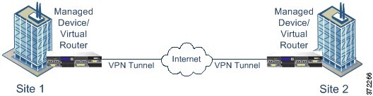
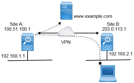
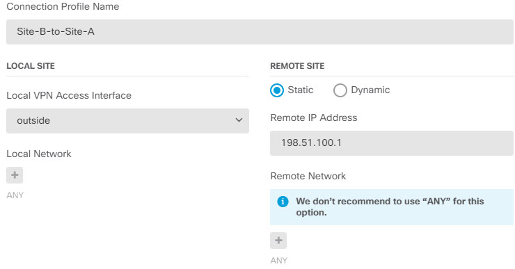
You can configure only point-to-point VPN connections using FDM. Although all connections are point-to-point, you can link into larger hub-and-spoke or meshed VPNs by defining each of the tunnels in which your device participates.

The following diagram displays a typical point-to-point VPN topology. In a point-to-point VPN topology, two endpoints communicate directly with each other. You configure the two endpoints as peer devices, and either device can start the secured connection.

Diagram illustrating a point-to-point VPN topology

Establishing Site-to-Site VPN Connections with Dynamically-Addressed Peers

You can create site-to-site VPN connections to peers even when you do not know the peer’s IP address. This can be useful in the following situations:

  • If the peer obtains its address using DHCP, you cannot depend on the remote endpoint having a specific static IP address.

  • When you want to allow an indeterminate number of remote peers to establish a connection with the device, which will serve as a hub in a hub-and-spoke topology.

When you need to establish a secure connection to a dynamically-addressed peer B, you need to ensure that your end of the connection, A, has a static IP address. Then, when you create the connection on A, specify that the peer’s address is dynamic. However, when you configure the connection on the peer B, ensure that you enter the IP address for A as the remote-peer address.

When the system establishes site-to-site VPN connections, any connections where the peer has a dynamic address will be response-only. That is, the remote peer must be the one that initiates the connection. When the remote peer attempts to establish the connection, your device validates the connection using the preshared key or the certificate, whichever method you defined in the connection.

Because the VPN connection is established only after the remote peer initiates the connection, any outbound traffic that matches access control rules that allow traffic in the VPN tunnel will be dropped until that connection is established. This ensures that data does not leave your network without the appropriate encryption and VPN protection.

Managing Site-to-Site VPNs

A virtual private network (VPN) is a network connection that establishes a secure tunnel between remote peers using a public source, such as the Internet or other network. VPNs use tunnels to encapsulate data packets within normal IP packets for forwarding over IP-based networks. They use encryption to ensure privacy and authentication to ensure the integrity of data.

You can create VPN connections to peer devices. All connections are point-to-point, but you can link the device into larger hub-and-spoke or meshed VPNs by configuring all relevant connections.

Before you begin

The following facts control the type and number of site-to-site VPN connections that you can recreate:

  • VPN connections use encryption to secure network privacy. The encryption algorithms that you can use depend on whether your base license allows strong encryption. This is controlled by whether you selected the option to allow export-controlled functionality on the device when you registered with Cisco Smart License Manager. If you are using the evaluation license, or you did not enable export-controlled functionality, you cannot use strong encryption.

  • You can create at most 20 unique IPsec profiles. Uniqueness is determined by the combination of IKEv1/v2 proposals and certificates, connection type, DH group and SA lifetime. You can reuse existing profiles. Thus, if you use the same settings for all your site-to-site VPN connections, you have one unique IPsec profile. Once you reach the limit of 20 unique IPsec profiles, you cannot create new site-to-site VPN connections unless you use the same combination of attributes that you used for an existing connection profile.

Procedure


Step 1

Click Device, then click View Configuration in the Site-to-Site VPN group.

This opens the Site-to-Site VPN page, which lists all of the connections that you have configured.

Step 2

Do any of the following.

  • To create a new Site-to-Site VPN connection, click the + button. See Configuring a Site-to-Site VPN Connection.

    If there are no connections yet, you can also click the Create Site-to-Site Connection button.

  • To edit an existing connection, click the edit icon (edit icon) for the connection. See Configuring a Site-to-Site VPN Connection.

  • To copy a summary of the connection configuration to the clipboard, click the copy icon (Copy connection summary to clipboard button.) for the connection. You can paste this information in a document and send it to the administrator for the remote device to help configure that end of the connection.

  • To delete a connection that you no longer need, click the delete icon (delete icon) for the connection.


Configuring a Site-to-Site VPN Connection

You can create a point-to-point VPN connection to link your device to another device, assuming that you have the cooperation and permission of the remote device owner. Although all connections are point-to-point, you can link into larger hub-and-spoke or meshed VPNs by defining each of the tunnels in which your device participates.


Note

You can create a single VPN connection per local network/remote network combination. However, you can create multiple connections for a local network if the remote network is unique in each connection profile.


Procedure


Step 1

Click Device, then click View Configuration in the Site-to-Site VPN group.

Step 2

Do any of the following:

  • To create a new Site-to-Site VPN connection, click the + button.

    If there are no connections yet, you can also click the Create Site-to-Site Connection button.

  • To edit an existing connection, click the edit icon (edit icon) for the connection.

To delete a connection that you no longer need, click the delete icon (delete icon) for the connection.

Step 3

Define the endpoints of the point-to-point VPN connection.

  • Connection Profile Name—The name for this connection, up to 64 characters without spaces. For example, MainOffice. You cannot use an IP address as the name.

  • Local Site—These options define the local endpoint.

    • Local VPN Access Interface—Select the interface to which the remote peer can connect. This is typically the outside interface. The interface cannot be a member of a bridge group.

    • Local Network—Click + and select the network objects that identify the local networks that should participate in the VPN connection. Users on these networks will be able to reach the remote networks through the connection.

    Note 

    You can use IPv4 or IPv6 addresses for these networks, but you must have a matching address type on each side of the connection. For example, the VPN connection for a local IPv4 network must have at least one remote IPv4 network. You can combine IPv4 and IPv6 on both sides of a singe connection. The protected networks for the endpoints cannot overlap.

  • Remote Site—These options define the remote endpoint.

    • Static/Dynamic—Whether the IP address of the remote peer is statically or dynamically defined (for example, through DHCP). If you select Static, also enter the remote peer's IP address. If you select Dynamic, only the remote peer will be able to initiate this VPN connection.

    • Remote IP Address (Static addressing only.)—Enter the IP address of the remote VPN peer's interface that will host the VPN connection.

    • Remote Network—Click + and select the network objects that identify the remote networks that should participate in the VPN connection. Users on these networks will be able to reach the local networks through the connection.

Step 4

Click Next.

Step 5

Define the privacy configuration for the VPN.

Note 

Your license determines which encryption protocols you can select. You must qualify for strong encryption, i.e. satisfy export controls, to choose any but the most basic options.

  • IKE Version 2, IKE Version 1—Choose the IKE versions to use during Internet Key Exchange (IKE) negotiations. Select either or both options as appropriate. When the device attempts to negotiate a connection with the other peer, it uses whichever versions you allow and that the other peer accepts. If you allow both versions, the device automatically falls back to the other version if negotiations are unsuccessful with the initially chosen version. IKEv2 is always tried first if it is configured. Both peers must support IKEv2 to use it in a negotiation.

  • IKE Policy—Internet Key Exchange (IKE) is a key management protocol that is used to authenticate IPsec peers, negotiate and distribute IPsec encryption keys, and automatically establish IPsec security associations (SAs). This is a global policy: the objects you enable are applied to all VPNs. Click Edit to examine the current globally-enabled policies per IKE version, and to enable and create new policies. For more information, see Configuring the Global IKE Policy.

  • IPsec Proposal—The IPsec proposal defines the combination of security protocols and algorithms that secure traffic in an IPsec tunnel. Click Edit and select the proposals for each IKE version. Select all proposals that you want to allow. Click Set Default to simply select the system defaults, which differ based on your export compliance. The system negotiates with the peer, starting from the strongest to the weakest proposal, until a match is agreed upon. For more information, see Configuring IPsec Proposals.

  • Authentication Type—How you want to authenticate the peers in the VPN connection, either Preshared Manual Key or Certificate. You also need to fill in the following fields based on your selection. For IKEv1, your selection must match the authentication method selected in the IKEv1 policy object configured for the connection. For detailed information on the options, see Deciding Which Authentication Method to Use.

    • (IKEv2) Local Preshared Key, Remote Peer Preshared Key—The keys defined on this device and on the remote device for the VPN connection. These keys can be different in IKEv2. The key can be 1-127 alphanumeric characters.

    • (IKEv1) Preshared Key—The key that is defined on both the local and remote device. The key can be 1-127 alphanumeric characters.

    • Certificate—The device identity certificate for the local peer. This must be a certificate obtained from a Certificate Authority (CA); you cannot use a self-signed certificate. If you have not uploaded the certificate, click the Create New Object link. You will also need to upload the root and any intermediate trusted CA certificates used to sign the identity certificate. If you have not already uploaded them, you can do so after completing this wizard.

  • NAT Exempt—Whether to exempt the VPN traffic from NAT policies on the local VPN access interface. If you do not want NAT rules to apply to the local network, select the interface that hosts the local network. This option works only if the local network resides behind a single routed interface (not a bridge group member). If the local network is behind more than one routed interface, or one or more bridge group members, you must manually create the NAT exempt rules. For information on manually creating the required rules, see Exempting Site-to-Site VPN Traffic from NAT.

  • Diffie-Helman Group for Perfect Forward Secrecy—Whether to use Perfect Forward Secrecy (PFS) to generate and use a unique session key for each encrypted exchange. The unique session key protects the exchange from subsequent decryption, even if the entire exchange was recorded and the attacker has obtained the preshared or private keys used by the endpoint devices. To enable Perfect Forward Secrecy, select the Diffie-Hellman key derivation algorithm to use when generating the PFS session key in the Modulus Group list. If you enable both IKEv1 and IKEv2, the options are limited to those supported by IKEv1. For an explanation of the options, see Deciding Which Diffie-Hellman Modulus Group to Use.

Step 6

Click Next.

Step 7

Review the summary and click Finish.

The summary information is copied to the clipboard. You can paste the information in a document and use it to help you configure the remote peer, or to send it to the party responsible for configuring the peer.

You must take additional steps to allow traffic within the VPN tunnel, as explained in Allowing Traffic Through the Site-to-Site VPN.

After you deploy the configuration, log into the device CLI and use the show ipsec sa command to verify that the endpoints establish a security association. See Verifying Site-to-Site VPN Connections.


Allowing Traffic Through the Site-to-Site VPN

You can use one of the following techniques to enable traffic flow in the site-to-site VPN tunnel.

  • Configure the sysopt connection permit-vpn command, which exempts traffic that matches the VPN connection from the access control policy. The default for this command is no sysopt connection permit-vpn , which means VPN traffic must also be allowed by the access control policy.

    This is the more secure method to allow traffic in the VPN, because external users cannot spoof IP addresses in the remote protected network. The downside is that the VPN traffic will not be inspected, which means that intrusion and file protection, URL filtering, or other advanced features will not be applied to the traffic. This also means that no connection events will be generated for the traffic, and thus statistical dashboards will not reflect VPN connections.

    The preferred method to configure this command is to create a remote access VPN connection profile in which you select the Bypass Access Control policy for decrypted traffic option. If you do not want to configure RA VPN, or you cannot configure RA VPN, you can use FlexConfig to configure the command.

  • Create access control rules to allow connections from the remote network. This method ensures that VPN traffic is inspected and advanced services can be applied to the connections. The downside is that it opens the possibility for external users to spoof IP addresses and thus gain access to your internal network.

Configuring the Global IKE Policy

Internet Key Exchange (IKE) is a key management protocol that is used to authenticate IPsec peers, negotiate and distribute IPsec encryption keys, and automatically establish IPsec security associations (SAs).

The IKE negotiation comprises two phases. Phase 1 negotiates a security association between two IKE peers, which enables the peers to communicate securely in Phase 2. During Phase 2 negotiation, IKE establishes SAs for other applications, such as IPsec. Both phases use proposals when they negotiate a connection. An IKE proposal is a set of algorithms that two peers use to secure the negotiation between them. IKE negotiation begins by each peer agreeing on a common (shared) IKE policy. This policy states which security parameters are used to protect subsequent IKE negotiations.

IKE policy objects define the IKE proposals for these negotiations. The objects that you enable are the ones used when the peers negotiate a VPN connection: you cannot specify different IKE policies per connection. The relative priority of each object determines which of these policies are tried first, with the lower number being higher priority. The connection is not established if the negotiation fails to find a policy that both peers can support.

To define the global IKE policy, you select which objects to enable for each IKE version. If the pre-defined objects do not satisfy your requirements, create new policies to enforce your security policy.

The following procedure explains how to configure the global policy through the Objects page. You can also enable, disable, and create policies when editing a VPN connection by clicking Edit for the IKE Policy settings.


Note

You can enable up to 20 IKE policies.


Procedure


Step 1

Select Objects, then select IKE Policies from the table of contents.

Policies for IKEv1 and IKEv2 are shown in separate lists.

Step 2

Enable the IKE policies you want to allow for each IKE version.

  1. Select IKEv1 or IKEv2 above the object table to show the policies for that version.

  2. Click the State toggle to enable the appropriate objects and to disable objects that do not meet your requirements.

    If some of your security requirements are not reflected in the existing objects, define new ones to implement your requirements. For details, see the following topics:

  3. Verify that the relative priorities match your requirements.

    If you need to change the priority of a policy, edit it. If the policy is a pre-defined system policy, you need to create your own version of the policy to change the priority.

    The priority is relative, and not absolute. For example, priority 80 is higher than 160. If 80 is the highest priority object that you enable, that becomes your first-choice policy. If you then enable a policy with priority 25, that becomes your first-choice policy.

  4. If you use both IKE versions, repeat the process for the other version.


Configuring IKEv1 Policies

Internet Key Exchange (IKE) version 1 policy objects contain the parameters required for IKEv1 policies when defining VPN connections. IKE is a key management protocol that facilitates the management of IPsec-based communications. It is used to authenticate IPsec peers, negotiate and distribute IPsec encryption keys, and automatically establish IPsec security associations (SAs).

There are several pre-defined IKEv1 policies. If any suit your needs, simply enable them by clicking the State toggle. You can also create new policies to implement other combinations of security settings. You cannot edit or delete system-defined objects.

The following procedure explains how you can create and edit objects directly through the Objects page. You can also create IKEv1 Policy objects while editing the IKEv1 settings in a VPN connection by clicking the Create New IKE Policy link shown in the object list.

Procedure

Step 1

Select Objects, then select IKE Policies from the table of contents.

Step 2

Select IKEv1 above the object table to show IKEv1 policies.

Step 3

If any of the system-defined policies meet your requirements, click the State toggle to enable them.

Also use the State toggle to disable unwanted policies. The relative priority determines which of these policies are tried first, with the lower number being higher priority.

Step 4

Do one of the following:

  • To create an object, click the + button.

  • To edit an object, click the edit icon (edit icon) for the object.

To delete an unreferenced object, click the trash can icon (delete icon) for the object.

Step 5

Configure the IKEv1 properties.

  • PriorityThe relative priority of the IKE policy, from 1 to 65,535. The priority determines the order of the IKE policy compared by the two negotiating peers when attempting to find a common security association (SA). If the remote IPsec peer does not support the parameters selected in your highest priority policy, it tries to use the parameters defined in the next lowest priority. The lower the number, the higher the priority.

  • NameThe name of the object, up to 128 characters.

  • StateWhether the IKE policy is enabled or disabled. Click the toggle to change the state. Only enabled policies are used during IKE negotiations.

  • Authentication—The method of authentication to use between the two peers. For more information, see Deciding Which Authentication Method to Use.

    • Preshared Key—Use the preshared key that is defined on each device. These keys allow for a secret key to be shared between two peers and to be used by IKE during the authentication phase. If the peer is not configured with the same preshared key, the IKE SA cannot be established.

    • Certificate—Use the device identity certificates for the peers to identify each other. You must obtain these certificates by enrolling each peer in a Certificate Authority. You must also upload the trusted CA root and intermediate CA certificates used to sign the identity certificates in each peer. The peers can be enrolled in the same or a different CA. You cannot use self-signed certificates for either peer.

  • Encryption—The encryption algorithm used to establish the Phase 1 security association (SA) for protecting Phase 2 negotiations. For an explanation of the options, see Deciding Which Encryption Algorithm to Use.

  • Diffie-Hellman Group—The Diffie-Hellman group to use for deriving a shared secret between the two IPsec peers without transmitting it to each other. A larger modulus provides higher security but requires more processing time. The two peers must have a matching modulus group. For an explanation of the options, see Deciding Which Diffie-Hellman Modulus Group to Use.

  • Hash—The hash algorithm for creating a message digest, which is used to ensure message integrity. For an explanation of the options, see Deciding Which Hash Algorithms to Use.

  • LifetimeThe lifetime of the security association (SA), in seconds, from 120 to 2147483647 or blank. When the lifetime is exceeded, the SA expires and must be renegotiated between the two peers. As a general rule, the shorter the lifetime (up to a point), the more secure your IKE negotiations will be. However, with longer lifetimes, future IPsec security associations can be set up more quickly than with shorter lifetimes. The default is 86400. To specify an unlimited lifetime, enter no value (leave the field blank).

Step 6

Click OK to save your changes.


Configuring IKEv2 Policies

Internet Key Exchange (IKE) version 2 policy objects contain the parameters required for IKEv2 policies when defining VPN connections. IKE is a key management protocol that facilitates the management of IPsec-based communications. It is used to authenticate IPsec peers, negotiate and distribute IPsec encryption keys, and automatically establish IPsec security associations (SAs).

There are several pre-defined IKEv2 policies. If any suit your needs, simply enable them by clicking the State toggle. You can also create new policies to implement other combinations of security settings. You cannot edit or delete system-defined objects.

The following procedure explains how you can create and edit objects directly through the Objects page. You can also create IKEv2 Policy objects while editing the IKEv2 settings in a VPN connection by clicking the Create New IKE Policy link shown in the object list.

Procedure

Step 1

Select Objects, then select IKE Policies from the table of contents.

Step 2

Select IKEv2 above the object table to show IKEv2 policies.

Step 3

If any of the system-defined policies meet your requirements, click the State toggle to enable them.

Also use the State toggle to disable unwanted policies. The relative priority determines which of these policies are tried first, with the lower number being higher priority.

Step 4

Do one of the following:

  • To create an object, click the + button.

  • To edit an object, click the edit icon (edit icon) for the object.

To delete an unreferenced object, click the trash can icon (delete icon) for the object.

Step 5

Configure the IKEv2 properties.

  • PriorityThe relative priority of the IKE policy, from 1 to 65,535. The priority determines the order of the IKE policy compared by the two negotiating peers when attempting to find a common security association (SA). If the remote IPsec peer does not support the parameters selected in your highest priority policy, it tries to use the parameters defined in the next lowest priority. The lower the number, the higher the priority.

  • NameThe name of the object, up to 128 characters.

  • StateWhether the IKE policy is enabled or disabled. Click the toggle to change the state. Only enabled policies are used during IKE negotiations.

  • Encryption—The encryption algorithm used to establish the Phase 1 security association (SA) for protecting Phase 2 negotiations. Select all algorithms that you want to allow, although you cannot include both mixed-mode (AES-GCM) and normal mode options in the same policy. (Normal mode requires that you select an integrity hash, whereas mixed mode prohibits a separate integrity hash selection.) The system negotiates with the peer, starting from the strongest to the weakest algorithm, until a match is agreed upon. For an explanation of the options, see Deciding Which Encryption Algorithm to Use.

  • Diffie-Hellman Group—The Diffie-Hellman group to use for deriving a shared secret between the two IPsec peers without transmitting it to each other. A larger modulus provides higher security but requires more processing time. The two peers must have a matching modulus group. Select all algorithms that you want to allow. The system negotiates with the peer, starting from the strongest to the weakest group, until a match is agreed upon. For an explanation of the options, see Deciding Which Diffie-Hellman Modulus Group to Use.

  • Integrity Hash—The integrity portion of the hash algorithm for creating a message digest, which is used to ensure message integrity. Select all algorithms that you want to allow. The system negotiates with the peer, starting from the strongest to the weakest algorithm, until a match is agreed upon. The integrity hash is not used with the AES-GCM encryption options. For an explanation of the options, see Deciding Which Hash Algorithms to Use.

  • Pseudo Random Function (PRF) Hash—The pseudo-random function (PRF) portion of the hash algorithm, which is used as the algorithm to derive keying material and hashing operations required for the IKEv2 tunnel encryption. In IKEv1, the Integrity and PRF algorithms are not separated, but in IKEv2, you can specify different algorithms for these elements. Select all algorithms that you want to allow. The system negotiates with the peer, starting from the strongest to the weakest algorithm, until a match is agreed upon. For an explanation of the options, see Deciding Which Hash Algorithms to Use.

  • LifetimeThe lifetime of the security association (SA), in seconds, from 120 to 2147483647 or blank. When the lifetime is exceeded, the SA expires and must be renegotiated between the two peers. As a general rule, the shorter the lifetime (up to a point), the more secure your IKE negotiations will be. However, with longer lifetimes, future IPsec security associations can be set up more quickly than with shorter lifetimes. The default is 86400. To specify an unlimited lifetime, enter no value (leave the field blank).

Step 6

Click OK to save your changes.


Configuring IPsec Proposals

IPsec is one of the most secure methods for setting up a VPN. IPsec provides data encryption at the IP packet level, offering a robust security solution that is standards-based. With IPsec, data is transmitted over a public network through tunnels. A tunnel is a secure, logical communication path between two peers. Traffic that enters an IPsec tunnel is secured by a combination of security protocols and algorithms called a transform set. During the IPsec security association (SA) negotiation, peers search for a transform set that is the same at both peers.

There are separate IPsec proposal objects based on the IKE version, IKEv1, or IKEv2:

  • When you create an IKEv1 IPsec proposal, you select the mode in which IPsec operates, and define the required encryption and authentication types. You can select single options for the algorithms. If you want to support multiple combinations in a VPN, create and select multiple IKEv1 IPsec Proposal objects.

  • When you create an IKEv2 IPsec proposal, you can select all of the encryption and hash algorithms allowed in a VPN. The system orders the settings from the most secure to the least secure and negotiates with the peer until a match is found. This allows you to potentially send a single proposal to convey all the allowed combinations instead of the need to send each allowed combination individually as with IKEv1.

The Encapsulating Security Protocol (ESP) is used for both IKEv1 and IKEv2 IPsec proposals. It provides authentication, encryption, and antireplay services. ESP is IP protocol type 50.


Note

We recommend using both encryption and authentication on IPsec tunnels.


The following topics explain how to configure IPsec proposals for each IKE version.

Configuring IPsec Proposals for IKEv1

Use IKEv1 IPsec Proposal objects configure the IPsec proposal used during IKE Phase 2 negotiations. The IPsec proposal defines the combination of security protocols and algorithms that secure traffic in an IPsec tunnel.

There are several pre-defined IKEv1 IPsec proposals. You can also create new proposals to implement other combinations of security settings. You cannot edit or delete system-defined objects.

The following procedure explains how you can create and edit objects directly through the Objects page. You can also create IKEv1 IPsec Proposals objects while editing the IKEv1 IPsec settings in a VPN connection by clicking the Create New IPsec Proposal link shown in the object list.

Procedure

Step 1

Select Objects, then select IPsec Proposals from the table of contents.

Step 2

Select IKEv1 above the object table to show IKEv1 IPsec proposals.

Step 3

Do one of the following:

  • To create an object, click the + button.

  • To edit an object, click the edit icon (edit icon) for the object.

To delete an unreferenced object, click the trash can icon (delete icon) for the object.

Step 4

Configure the IKEv1 IPsec proposal properties.

  • NameThe name of the object, up to 128 characters.

  • Mode—The mode in which the IPSec tunnel operates.

    • Tunnel mode encapsulates the entire IP packet. The IPSec header is added between the original IP header and a new IP header. This is the default. Use tunnel mode when the firewall is protecting traffic to and from hosts positioned behind the firewall. Tunnel mode is the normal way regular IPSec is implemented between two firewalls (or other security gateways) that are connected over an untrusted network, such as the Internet.

    • Transport mode encapsulates only the upper-layer protocols of an IP packet. The IPSec header is inserted between the IP header and the upper-layer protocol header (such as TCP). Transport mode requires that both the source and destination hosts support IPSec, and can only be used when the destination peer of the tunnel is the final destination of the IP packet. Transport mode is generally used only when protecting a Layer 2 or Layer 3 tunneling protocol such as GRE, L2TP, and DLSW.

  • ESP Encryption—The Encapsulating Security Protocol (ESP) encryption algorithm for this proposal. For an explanation of the options, see Deciding Which Encryption Algorithm to Use.

  • ESP Hash—The hash or integrity algorithm to use for authentication. For an explanation of the options, see Deciding Which Hash Algorithms to Use.

Step 5

Click OK to save your changes.


Configuring IPsec Proposals for IKEv2

Use IKEv2 IPsec Proposal objects configure the IPsec proposal used during IKE Phase 2 negotiations. The IPsec proposal defines the combination of security protocols and algorithms that secure traffic in an IPsec tunnel.

There are several pre-defined IKEv2 IPsec proposals. You can also create new proposals to implement other combinations of security settings. You cannot edit or delete system-defined objects.

The following procedure explains how you can create and edit objects directly through the Objects page. You can also create IKEv2 IPsec Proposals objects while editing the IKEv2 IPsec settings in a VPN connection by clicking the Create New IPsec Proposal link shown in the object list.

Procedure

Step 1

Select Objects, then select IPsec Proposals from the table of contents.

Step 2

Select IKEv2 above the object table to show IKEv2 IPsec proposals.

Step 3

Do one of the following:

  • To create an object, click the + button.

  • To edit an object, click the edit icon (edit icon) for the object.

To delete an unreferenced object, click the trash can icon (delete icon) for the object.

Step 4

Configure the IKEv2 IPsec proposal properties.

  • NameThe name of the object, up to 128 characters.

  • Encryption—The Encapsulating Security Protocol (ESP) encryption algorithm for this proposal. Select all algorithms that you want to allow. The system negotiates with the peer, starting from the strongest to the weakest algorithm, until a match is agreed upon. For an explanation of the options, see Deciding Which Encryption Algorithm to Use.

  • Integrity Hash—The hash or integrity algorithm to use for authentication. Select all algorithms that you want to allow. The system negotiates with the peer, starting from the strongest to the weakest algorithm, until a match is agreed upon. For an explanation of the options, see Deciding Which Hash Algorithms to Use.

    Note 

    You should choose the null integrity algorithm if you select one of the AES-GCM/GMAC options as the encryption algorithm. These encryption standards do not use the integrity hash even if you select a non-null option.

Step 5

Click OK to save your changes.


Verifying Site-to-Site VPN Connections

After you configure a site-to-site VPN connection, and deploy the configuration to the device, verify that the system establishes the security association with the remote device.

If the connection cannot be established, use the ping interface interface_name remote_ip_address command from the device CLI to ensure there is a path through the VPN interface to the remote device. If there is no connection through the configured interface, you can leave off the interface interface_name keyword and determine if connectivity is through a different interface. You might have selected the wrong interface for the connection: you must select the interface that faces the remote device, not the interface that faces the protected network.

If there is a network path, check the IKE versions and keys configured and supported by both endpoints, and adjust the VPN connection as needed. Ensure that no access control or NAT rules are blocking the connection.

Procedure


Step 1

Log into the device CLI as explained in Logging Into the Command Line Interface (CLI).

Step 2

Use the show ipsec sa command to verify that the IPsec security association is established.

You should see that the VPN connection is established between your device (the local addr) and the remote peer (current_peer). The packets (pkts) counts should increase as you send traffic through the connection. The access list should show the local and remote networks for the connection.

For example, the following output shows an IKEv2 connection.


> show ipsec sa 
interface: site-a-outside
    Crypto map tag: s2sCryptoMap, seq num: 1, local addr: 192.168.2.15

      access-list |s2sAcl|0730e31c-1e5f-11e7-899f-27f6e1030344 
extended permit ip 192.168.1.0 255.255.255.0 192.168.3.0 255.255.255.0 
      local ident (addr/mask/prot/port): (192.168.1.0/255.255.255.0/0/0)
      remote ident (addr/mask/prot/port): (192.168.3.0/255.255.255.0/0/0)
      current_peer: 192.168.4.6


      #pkts encaps: 69, #pkts encrypt: 69, #pkts digest: 69
      #pkts decaps: 69, #pkts decrypt: 69, #pkts verify: 69
      #pkts compressed: 0, #pkts decompressed: 0
      #pkts not compressed: 69, #pkts comp failed: 0, #pkts decomp failed: 0
      #pre-frag successes: 0, #pre-frag failures: 0, #fragments created: 0
      #PMTUs sent: 0, #PMTUs rcvd: 0, #decapsulated frgs needing reassembly: 0
      #TFC rcvd: 0, #TFC sent: 0
      #Valid ICMP Errors rcvd: 0, #Invalid ICMP Errors rcvd: 0
      #send errors: 0, #recv errors: 0

      local crypto endpt.: 192.168.2.15/500, remote crypto endpt.: 192.168.4.6/500
      path mtu 1500, ipsec overhead 55(36), media mtu 1500
      PMTU time remaining (sec): 0, DF policy: copy-df
      ICMP error validation: disabled, TFC packets: disabled
      current outbound spi: CD22739C
      current inbound spi : 52D2F1E4

    inbound esp sas:
      spi: 0x52D2F1E4 (1389556196)
         SA State: active
         transform: esp-aes-gcm-256 esp-null-hmac no compression 
         in use settings ={L2L, Tunnel, PFS Group 19, IKEv2, }
         slot: 0, conn_id: 62738432, crypto-map: s2sCryptoMap
         sa timing: remaining key lifetime (kB/sec): (4285434/28730)
         IV size: 8 bytes
         replay detection support: Y
         Anti replay bitmap: 
          0xFFFFFFFF 0xFFFFFFFF
    outbound esp sas:
      spi: 0xCD22739C (3441587100)
         SA State: active
         transform: esp-aes-gcm-256 esp-null-hmac no compression 
         in use settings ={L2L, Tunnel, PFS Group 19, IKEv2, }
         slot: 0, conn_id: 62738432, crypto-map: s2sCryptoMap
         sa timing: remaining key lifetime (kB/sec): (4055034/28730)
         IV size: 8 bytes
         replay detection support: Y
         Anti replay bitmap: 
          0x00000000 0x00000001

The following output shows an IKEv1 connection.


> show ipsec sa 
interface: site-a-outside
    Crypto map tag: s2sCryptoMap, seq num: 1, local addr: 192.168.2.15

      access-list |s2sAcl|0730e31c-1e5f-11e7-899f-27f6e1030344 
extended permit ip 192.168.1.0 255.255.255.0 192.168.3.0 255.255.255.0 
      local ident (addr/mask/prot/port): (192.168.1.0/255.255.255.0/0/0)
      remote ident (addr/mask/prot/port): (192.168.3.0/255.255.255.0/0/0)
      current_peer: 192.168.4.6


      #pkts encaps: 10, #pkts encrypt: 10, #pkts digest: 10
      #pkts decaps: 10, #pkts decrypt: 10, #pkts verify: 10
      #pkts compressed: 0, #pkts decompressed: 0
      #pkts not compressed: 10, #pkts comp failed: 0, #pkts decomp failed: 0
      #pre-frag successes: 0, #pre-frag failures: 0, #fragments created: 0
      #PMTUs sent: 0, #PMTUs rcvd: 0, #decapsulated frgs needing reassembly: 0
      #TFC rcvd: 0, #TFC sent: 0
      #Valid ICMP Errors rcvd: 0, #Invalid ICMP Errors rcvd: 0
      #send errors: 0, #recv errors: 0

      local crypto endpt.: 192.168.2.15/0, remote crypto endpt.: 192.168.4.6/0
      path mtu 1500, ipsec overhead 74(44), media mtu 1500
      PMTU time remaining (sec): 0, DF policy: copy-df
      ICMP error validation: disabled, TFC packets: disabled
      current outbound spi: 077D72C9
      current inbound spi : AC146DEC

    inbound esp sas:
      spi: 0xAC146DEC (2887020012)
         SA State: active
         transform: esp-aes-256 esp-sha-hmac no compression 
         in use settings ={L2L, Tunnel, PFS Group 5, IKEv1, }
         slot: 0, conn_id: 143065088, crypto-map: s2sCryptoMap
         sa timing: remaining key lifetime (kB/sec): (3914999/28567)
         IV size: 16 bytes
         replay detection support: Y
         Anti replay bitmap: 
          0x00000000 0x000007FF
    outbound esp sas:
      spi: 0x077D72C9 (125661897)
         SA State: active
         transform: esp-aes-256 esp-sha-hmac no compression 
         in use settings ={L2L, Tunnel, PFS Group 5, IKEv1, }
         slot: 0, conn_id: 143065088, crypto-map: s2sCryptoMap
         sa timing: remaining key lifetime (kB/sec): (3914999/28567)
         IV size: 16 bytes
         replay detection support: Y
         Anti replay bitmap: 
          0x00000000 0x00000001

Step 3

Use the show isakmp sa command to verify the IKE security associations.

You can use the command without the sa keyword (or use the stats keyword instead) to view IKE statistics.

For example, the following output shows an IKEv2 security association.


> show isakmp sa

There are no IKEv1 SAs

IKEv2 SAs:

Session-id:15317, Status:UP-ACTIVE, IKE count:1, CHILD count:1

Tunnel-id Local             Remote            Status   Role
592216161 192.168.2.15/500  192.168.4.6/500   READY    INITIATOR
      Encr: AES-GCM, keysize: 256, Hash: N/A, DH Grp:21, Auth sign: PSK, Auth verify: PSK
      Life/Active Time: 86400/12 sec
Child sa: local selector  192.168.1.0/0 - 192.168.1.255/65535
          remote selector 192.168.3.0/0 - 192.168.3.255/65535
          ESP spi in/out: 0x52d2f1e4/0xcd22739c  

The following output shows an IKEv1 security association.


> show isakmp sa 

IKEv1 SAs:

   Active SA: 1
    Rekey SA: 0 (A tunnel will report 1 Active and 1 Rekey SA during rekey)
Total IKE SA: 1

1   IKE Peer: 192.168.4.6
    Type    : L2L             Role    : initiator 
    Rekey   : no              State   : MM_ACTIVE 

There are no IKEv2 SAs


Monitoring Site-to-Site VPN

To monitor and troubleshoot site-to-site VPN connections, open the CLI console or log into the device CLI and use the following commands.

  • show ipsec sa displays the VPN sessions (security associations). You can reset these statistics using the clear ipsec sa counters command.

  • show ipsec keyword displays IPsec operational data and statistics. Enter show ipsec ? to see the available keywords.

  • show isakmp displays ISAKMP operational data and statistics.

Examples for Site-to-Site VPN

The following are examples of configuring site-to-site VPN.

Exempting Site-to-Site VPN Traffic from NAT

When you have a site-to-site VPN connection defined on an interface, and you also have NAT rules for that interface, you can optionally exempt the traffic on the VPN from the NAT rules. You might want to do this if the remote end of the VPN connection can handle your internal addresses.

When you create the VPN connection, you can select the NAT Exempt option to create the rules automatically. However, this works only if your local protected network is connected through a single routed interface (not a bridge group member). If instead, the local networks in the connection reside behind two or more routed interfaces, or one or more bridge group members, you need to manually configure the NAT exempt rules.

To exempt VPN traffic from NAT rules, you create an identity manual NAT rule for the local traffic when the destination is the remote network. Then, apply NAT to the traffic when the destination is anything else (for example, the Internet). If you have more than one interface for the local network, create rules for each interface. Also, consider the following suggestions:

  • If there is more than one local network in the connection, create a network object group to hold the objects that define the networks.

  • If you are including both IPv4 and IPv6 networks in the VPN, create separate identity NAT rules for each.

Consider the following example, which shows a site-to-site tunnel connecting the Boulder and San Jose offices. For traffic that you want to go to the Internet (for example from 10.1.1.6 in Boulder to www.example.com), you need a public IP address provided by NAT to access the Internet. The below example uses interface PAT rules. However, for traffic that you want to go over the VPN tunnel (for example from 10.1.1.6 in Boulder to 10.2.2.78 in San Jose), you do not want to perform NAT; you need to exempt that traffic by creating an identity NAT rule. Identity NAT simply translates an address to the same address.

Figure 1. Interface PAT and Identity NAT for Site-to-Site VPN

The following example explains the configuration for Firewall1 (Boulder). The example assumes that the inside interface is a bridge group, so you need to write the rules for each member interface. The process is the same if you have a single or multiple routed inside interfaces.


Note

This example assumes IPv4 only. If the VPN also includes IPv6 networks, create parallel rules for IPv6. Note that you cannot implement IPv6 interface PAT, so you need to create a host object with a unique IPv6 address to use for PAT.


Procedure


Step 1

Create the objects to define the various networks.

  1. Choose Objects.

  2. Select Network from the table of contents and click +.

  3. Identify the Boulder inside network.

    Name the network object (for example, boulder-network), select Network, and enter the network address, 10.1.1.0/24.


    boulder-network object.

  4. Click OK.

  5. Click + and define the inside San Jose network.

    Name the network object (for example, sanjose-network), select Network, and enter the network address 10.2.2.0/24.


    sanjose-network object.

  6. Click OK.

Step 2

Configure manual identity NAT for the Boulder network when going over the VPN to San Jose on Firewall1 (Boulder).

  1. Select Policies > NAT.

  2. Click the + button.

  3. Configure the following properties:

    • Title = NAT Exempt 1_2 Boulder San Jose VPN (or another name of your choosing).

    • Create Rule For = Manual NAT.

    • Placement = Above a Specific Rule, and select the first rule in the Manual NAT Before Auto NAT section. You want to ensure that this rule comes before any general interface PAT rules for the destination interface. Otherwise, the rule might not be applied to the right traffic.

    • Type = Static.

    • Source Interface = inside1_2.

    • Destination Interface = outside.

    • Original Source Address = boulder-network network object.

    • Translated Source Address = boulder-network network object.

    • Original Destination Address = sanjose-network network object.

    • Translated Destination Address = sanjose-network network object.

      Note 

      Because you do not want to translate the destination address, you need to configure identity NAT for it by specifying the same address for the original and translated destination addresses. Leave all of the port fields blank. This rule configures identity NAT for both source and destination.


    Identity NAT rule.

  4. On the Advanced tab, select Do not proxy ARP on Destination interface.

  5. Click OK.

  6. Repeat the process to create equivalent rules for each of the other inside interfaces.

Step 3

Configure manual dynamic interface PAT when going to the Internet for the inside Boulder network on Firewall1 (Boulder).

Note 

There might already be dynamic interface PAT rules for the inside interfaces, covering any IPv4 traffic, as these are created by default during initial configuration. However, the configuration is shown here for completeness. Before completing these steps, check whether a rule already exists that covers the inside interface and network, and skip this step if it does.

  1. Click the + button.

  2. Configure the following properties:

    • Title = inside1_2 interface PAT (or another name of your choosing).

    • Create Rule For = Manual NAT.

    • Placement = Below a Specific Rule, and select the rule you created above for this interface in the Manual NAT Before Auto NAT section. Because this rule will apply to any destination address, the rule that uses sanjose-network as the destination must come before this rule, or the sanjose-network rule will never be matched. The default is to place new manual NAT rules at the end of the "NAT Rules Before Auto NAT" section, which is also sufficient.

    • Type = Dynamic.

    • Source Interface = inside1_2.

    • Destination Interface = outside.

    • Original Source Address = boulder-network network object.

    • Translated Source Address = Interface. This option configures interface PAT using the destination interface.

    • Original Destination Address = any.

    • Translated Destination Address = any.


    Interface PAT rule.

  3. Click OK.

  4. Repeat the process to create equivalent rules for each of the other inside interfaces.

Step 4

Commit your changes.

  1. Click the Deploy Changes icon in the upper right of the web page.

    Deploy changes button, highlighted when there are changes to deploy.

  2. Click the Deploy Now button.

    You can wait until deployment completes, or click OK and check the task list or deployment history later.

Step 5

If you are also managing Firewall2 (San Jose), you can configure similar rules for that device.

  • The manual identity NAT rule would be for sanjose-network when the destination is boulder-network. Create new interface objects for the Firewall2 inside and outside networks.

  • The manual dynamic interface PAT rule would be for sanjose-network when the destination is "any."


How to Provide Internet Access on the Outside Interface for External Site-to-Site VPN Users (Hair Pinning)

In a site-to-site VPN, you might want users on the remote networks to access the Internet through your device. However, because the remote users are entering your device on the same interface that faces the Internet (the outside interface), you need to bounce Internet traffic right back out of the outside interface. This technique is sometimes called hair pinning.

The following graphic shows an example. There is a site-to-site VPN tunnel configured between 198.51.100.1 (on the main site, Site A) and 203.0.113.1 (the remote site, Site B). All user traffic from the remote site inside network, 192.168.2.0/24, goes through the VPN. Thus, when a user on that network wants to go to a server on the Internet, such as www.example.com, the connection first goes through the VPN, then gets routed back out to the Internet from the 198.51.100.1 interface.


Network diagram for hair pinning in site-to-site VPN.

The following procedure explains how to configure this service. You must configure both endpoints of the VPN tunnel.

Before you begin

This procedure assumes you are using the default setting for permitting VPN traffic, which subjects the VPN traffic to the access control policy. In the running configuration, this is represented by the no sysopt connection permit-vpn command. If you instead enabled sysopt connection permit-vpn through FlexConfig, or by selecting the Bypass Access Control policy for decrypted traffic option in RA VPN connection profiles, the steps that configure access control rules are not needed.

Procedure


Step 1

(Site A, main site.) Configure the site-to-site VPN connection to remote Site B.

  1. Click Device, then click View Configuration in the Site-to-Site VPN group.

  2. Click + to add a new connection.

  3. Define the endpoints as follows, and then click Next:

    • Connection Profile Name—Give the connection a meaningful name, for example, Site-A-to-Site-B.

    • Local VPN Access Interface—Select the outside interface.

    • Local Network—Keep the default, Any.

    • Remote IP Address—Enter the IP address of the remote peer’s outside interface. In this example, 203.0.113.1.

    • Remote Network—Click +, then select the network object that defines the remote peer’s protected network. In this example, 192.168.2.0/24. You can click Create New Network to create the object now.

    The following graphic shows how the first step should look.


    Site A site-to-site VPN connection profile settings.

  4. Define the privacy configuration, then click Next.

    • IKE Policy—The IKE settings have no impact on hair pinning. Simply select the IKE versions, policies, and proposals that fit your security needs. Make note of the local and remote pre-shared keys you enter: you will need these when configuring the remote peer.

    • NAT Exempt—Select the inside interface.


      Site A connection profile, NAT exempt setting.

    • Diffie Helman Group for Perfect Forward Secrecy—This setting has no impact on hair pinning. Configure it as you see fit.

  5. Click Finish.

    The connection summary is copied to the clipboard. You can paste it into a text file or other document to help you configure the remote peer.

Step 2

(Site A, main site.) Configure the NAT rule to translate all connections going out the outside interface to ports on the outside IP address (interface PAT).

When you complete the initial device configuration, the system creates a NAT rule named InsideOutsideNatRule. This rule applies interface PAT to IPv4 traffic from any interface that exits the device through the outside interface. Because the outside interface is included in “Any” source interface, the rule you need already exists, unless you edited it or deleted it.

The following procedure explains how to create the rule you need.

  1. Click Policies > NAT.

  2. Do one of the following:

    • To edit the InsideOutsideNatRule, mouse over the Action column and click the edit icon (edit icon).

    • To create a new rule, click +.

  3. Configure a rule with the following properties:

    • Title—For a new rule, enter a meaningful name without spaces. For example, OutsideInterfacePAT.

    • Create Rule ForManual NAT.

    • PlacementBefore Auto NAT Rules (the default).

    • TypeDynamic.

    • Original Packet—For Source Address, select either Any or any-ipv4. For Source Interface, ensure that you select Any (which is the default). For all other Original Packet options, keep the default, Any.

    • Translated Packet—For Destination Interface, select outside. For Translated Address, select Interface. For all other Translated Packet options, keep the default, Any.

    The following graphic shows the simple case where you select Any for the source address.


    NAT rule for interface PAT.

  4. Click OK.

Step 3

(Site A, main site.) Configure an access control rule to allow access to the protected network on Site B.

Simply creating a VPN connection does not automatically allow traffic on the VPN. You need to ensure that your access control policy allows traffic to the remote network.

The following procedure shows how to add a rule specifically for the remote network. Whether you need an additional rule depends on your existing rules.

  1. Click Policies > Access Control.

  2. Click + to create a new rule.

  3. Configure a rule with the following properties:

    • Order—Select a position in the policy before any other rule that might match these connections and block them. The default is to add the rule to the end of the policy. If you need to reposition the rule later, you can edit this option or simply drag and drop the rule to the right slot in the table.

    • Title—Enter a meaningful name without spaces. For example, Site-B-Network.

    • ActionAllow. You can select Trust if you do not want this traffic to be inspected for protocol violations or intrusions.

    • Source/Destination tab—For Destination > Network, select the same object you used in the VPN connection profile for the remote network. Leave the default, Any, for all other Source and Destination options.


      Site A access control rule to allow traffic to the remote network..

    • Application, URL, and Users tabs—Leave the default settings on these tabs, that is, nothing selected.

    • Intrusion, File tabs—You can optionally select intrusion or file policies to inspect for threats or malware.

    • Logging tab—You can optionally enable connection logging.

  4. Click OK.

Step 4

(Site A, main site.) Commit your changes.

  1. Click the Deploy Changes icon in the upper right of the web page.

    Deploy changes button, highlighted when there are changes to deploy.

  2. Click the Deploy Now button.

    You can wait until deployment completes, or click OK and check the task list or deployment history later. If you leave the window up, it will indicate that there are no pending changes after a successful deployment.

Step 5

(Site B, remote site.) Log into the remote site’s device, and configure the site-to-site VPN connection to Site A.

Use the connection summary obtained from the Site A device configuration to help you configure the Site B side of the connection.

  1. Click Device, then click View Configuration in the Site-to-Site VPN group.

  2. Click + to add a new connection.

  3. Define the endpoints as follows, and then click Next:

    • Connection Profile Name—Give the connection a meaningful name, for example, Site-B-to-Site-A.

    • Local VPN Access Interface—Select the outside interface.

    • Local Network—Click +, then select the network object that defines the local protected network. In this example, 192.168.2.0/24. You can click Create New Network to create the object now.

    • Remote IP Address—Enter the IP address of the main site’s outside interface. In this example, 198.51.100.1.

    • Remote Network—Keep the default, Any. Ignore the warning; it is not relevant for this use case.

    The following graphic shows how the first step should look.


    Site B VPN connection profile settings.

  4. Define the privacy configuration, then click Next.

    • IKE Policy—The IKE settings have no impact on hair pinning. Configure the same or compatible options as those on Site A’s end of the VPN connection. You must configure the pre-shared keys correctly: switch the local and remote keys (for IKEv2) as configured on the Site A device. For IKEv1, there is just one key, which must be the same on both peers.

    • NAT Exempt—Select the inside interface.


      Site B connection profile, NAT exempt setting.

    • Diffie Helman Group for Perfect Forward Secrecy—This setting has no impact on hair pinning. Match the setting used on Site A’s end of the VPN connection.

  5. Click Finish.

Step 6

(Site B, remote site.) Delete all NAT rules for the protected network so that all traffic leaving the site must go through the VPN tunnel.

Performing NAT on this device is unnecessary because the Site A device will do the address translation. But please examine your specific situation. If you have multiple internal networks and not all of them are participating in this VPN connection, do not delete NAT rules that you need for those networks.

  1. Click Policies > NAT.

  2. Do one of the following:

    • To delete rules, mouse over the Action column and click the delete icon (delete icon).

    • To edit rules so they no longer apply to the protected network, mouse over the Action column and click the edit icon (edit icon).

Step 7

(Site B, remote site.) Configure an access control rule to allow access from the protected network to the Internet.

The following example allows traffic from the protected network to any destination. You can adjust this to meet your specific requirements. You can also precede the rule with block rules to filter out undesirable traffic. Another option is to configure the block rules on the Site A device.

  1. Click Policies > Access Control.

  2. Click + to create a new rule.

  3. Configure a rule with the following properties:

    • Order—Select a position in the policy before any other rule that might match these connections and block them. The default is to add the rule to the end of the policy. If you need to reposition the rule later, you can edit this option or simply drag and drop the rule to the right slot in the table.

    • Title—Enter a meaningful name without spaces. For example, Protected-Network-to-Any.

    • ActionAllow. You can select Trust if you do not want this traffic to be inspected for protocol violations or intrusions.

    • Source/Destination tab—For Source > Network, select the same object you used in the VPN connection profile for the local network. Leave the default, Any, for all other Source and Destination options.


      Site B access rule for VPN Internet traffic.

    • Application, URL, and Users tabs—Leave the default settings on these tabs, that is, nothing selected.

    • Intrusion, File tabs—You can optionally select intrusion or file policies to inspect for threats or malware.

    • Logging tab—You can optionally enable connection logging.

  4. Click OK.

Step 8

(Site B, remote site.) Commit your changes.

  1. Click the Deploy Changes icon in the upper right of the web page.

    Deploy changes button, highlighted when there are changes to deploy.

  2. Click the Deploy Now button and wait for deployment to finish.

    You can wait until deployment completes, or click OK and check the task list or deployment history later. If you leave the window up, it will indicate that there are no pending changes after a successful deployment.