Getting Started

The following topics explain how to get started configuring the Firepower Threat Defense (FTD) .

Is This Guide for You?

This guide explains how to configure FTD using the Firepower Device Manager (FDM) web-based configuration interface included on the FTD devices.

The FDM lets you configure the basic features of the software that are most commonly used for small or mid-size networks. It is especially designed for networks that include a single device or just a few, where you do not want to use a high-powered multiple-device manager to control a large network containing many FTD devices.

If you are managing large numbers of devices, or if you want to use the more complex features and configurations that FTD allows, use the Firepower Management Center (FMC) to configure your devices instead of the integrated FDM.

You can use the FDM on the following devices.

Table 1. FDM Supported Models

Device Model

Minimum FTD Software Version

Firepower 1010, 1120, 1140

6.4

Firepower 1150

6.5

Firepower 2110, 2120, 2130, 2140

6.2.1

Firepower 4110, 4115, 4120, 4125, 4140, 4145, 4150

6.5

Firepower 9300

6.5

FTDv (FTDv)for VMware

6.2.2

FTDv for Kernel-based Virtual Machine (KVM) hypervisor

6.2.3

FTDv for the Microsoft Azure Cloud

6.5

ASA 5508-X, 5516-X

6.1

ASA 5525-X, 5545-X, 5555-X

6.1

ASA 5515-X

Note 

Support for the ASA 5515-X ends with 6.4 being the last allowed version. You cannot install version 6.5 or later on this model.

6.1

ISA 3000 (Cisco 3000 Series Industrial Security Appliances)

6.2.3

New Features in FDM/FTD Version 6.5.0

Released: September 26, 2019

The following table lists the new features available in FTD 6.5.0 when configured using FDM.

Feature

Description

FDM support for the Firepower 4100/9300.

You can now use FDM to configure FTD on the Firepower 4100/9300. Only native instances are supported; container instances are not supported.

FDM support for FTDv for the Microsoft Azure Cloud.

You can configure on FTDv for the Microsoft Azure Cloud using FDM.

Support for the Firepower 1150.

We introduced the FTD for the Firepower 1150.

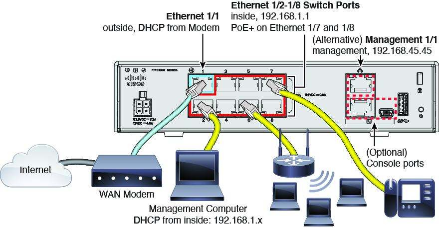
Firepower 1010 hardware switch support, PoE+ support.

The Firepower 1010 supports setting each Ethernet interface to be a switch port or a regular firewall interface. Assign each switch port to a VLAN interface. The Firepower 1010 also supports Power over Ethernet+ (PoE+) on Ethernet1/7 and Ethernet 1/8.

The default configuration now sets Ethernet1/1 as outside, and Ethernet1/2 through 1/8 as switch ports on the inside VLAN1 interface. Upgrading to version 6.5 retains the existing interface configuration.

Interface scan and replace.

An interface scan detects any added, removed, or restored interfaces on the chassis. You can also replace an old interface with a new interface in the configuration, making interface changes seamless.

Improved interfaces display.

The Device > Interfaces page has been reorganized. There are now separate tabs for physical interfaces, bridge groups, EtherChannels, and VLANs. For any given device model, only those tabs relevant for the model are shown. For example, the VLANs tab is available on the Firepower 1010 model only. In addition, the lists provide more detailed information about the configuration and usage of each interface.

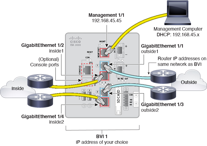
ISA 3000 new default configuration.

The ISA 3000 default configuration has changed so that:

  • All interfaces are bridge group members in BVI1, which is unnamed so it does not participate in routing

  • GigabitEthernet1/1 and 1/3 are outside interfaces, and GigabitEthernet1/2 and 1/4 are inside interfaces

  • Hardware bypass is enabled for each inside/outside pair, when available

  • All traffic is allowed from inside to outside, and outside to inside

Upgrading to version 6.5 retains the existing interface configuration.

Support ends for the ASA 5515-X. The last supported release is FTD 6.4.

You cannot install FTD 6.5 on an ASA 5515-X. The last supported release for the ASA 5515-X is FTD 6.4.

Support for Common Industrial Protocol (CIP) and Modbus application filtering in access control rules on Cisco ISA 3000 devices.

You can enable the Common Industrial Protocol (CIP) and Modbus preprocessors on Cisco ISA 3000 devices, and filter on CIP and Modbus applications in access control rules. All CIP application names start with “CIP,” such as CIP Write. There is only one application for Modbus.

To enable the preprocessors, you must go into expert mode in a CLI session (SSH or Console) and issue the sudo /usr/local/sf/bin/enable_scada.sh {cip | modbus | both} command. You must issue this command after every deployment, as deployment turns off the preprocessors.

Precision Time Protocol (PTP) configuration for ISA 3000 devices.

You can use FlexConfig to configure the Precision Time Protocol (PTP) on ISA 3000 devices. PTP is a time-synchronization protocol developed to synchronize the clocks of various devices in a packet-based network. The protocol is designed specifically for industrial, networked measurement and control systems.

We now allow you to include the ptp and igmp (interface mode) commands, and the global commands ptp mode e2etransparent and ptp domain , in FlexConfig objects. We also added the show ptp command to the FTD CLI.

EtherChannel (port channel) interfaces.

You can configure EtherChannel interfaces, which are also known as port channels.

Note 

You can only add EtherChannels in FDM to the Firepower 1000 and 2100 series. The Firepower 4100/9300 supports EtherChannels, but you must perform all hardware configuration of EtherChannels in FXOS on the chassis. Firepower 4100/9300 EtherChannels appear in the FDM Interfaces page alongside single physical interfaces.

We updated the Device > Interfaces page to allow the creation of EtherChannels.

Ability to reboot and shut down the system from FDM.

You can now reboot or shut down the system from the new Reboot/Shutdown system settings page. Previously, you needed to issue the reboot and shutdown commands through the CLI Console in FDM or from an SSH or console session. You must have Administrator privileges to use these commands.

Support for the failover command in the FDM CLI Console.

You can now issue the failover command in the FDM CLI Console.

Service Level Agreement (SLA) Monitor for static routes.

Configure Service Level Agreement (SLA) Monitor objects for use with static routes. By using an SLA monitor, you can track the health of a static route and automatically replace a failed route with a new one. We added SLA Monitors to the Objects page, and updated static routes so you can select the SLA Monitor object.

Routing changes in Smart CLI and the FTD API.

This release includes some changes to routing configuration in Smart CLI and the FTD API. In previous releases, there was a single Smart CLI template for BGP. Now, there are separate templates for BGP (the routing process configuration) and BGP General Settings (global settings).

In the FTD API, the paths for all methods have changed, with “/virtualrouters” inserted in the paths, with the exception of the new BGP general settings methods.

  • The path for static route methods was /devices/default/routing/{parentId}/staticrouteentries, and it is now /devices/default/routing/virtualrouters/default/staticrouteentries.

  • BGP methods were split into two new paths: /devices/default/routing/bgpgeneralsettings and /devices/default/routing/virtualrouters/default/bgp.

  • OSPF paths are now /devices/default/routing/virtualrouters/default/ospf and /devices/default/routing/virtualrouters/default/ospfinterfacesettings.

If you are using the FTD API to configure any routing process, please examine your calls and correct as necessary.

New URL category and reputation database.

The system uses a different URL database, from Cisco Talos. The new database has some differences in URL categories. Upon upgrade, if any access control or SSL decryption rules use categories that no longer exist, the system will replace the category with an appropriate new category. To make the change effective, deploy the configuration after upgrade. The pending changes dialog will show details about the category changes. You might want to examine your URL filtering policies to verify that they continue to provide the desired results.

We also added a URL lookup feature to the URL tabs in the access control and SSL decryption policies, and on the Device > System Settings > URL Filtering Preferences page. You can use this feature to check which category a particular URL is assigned to. If you disagree, there is also a link to submit a category dispute. Both of these features take you to an external web site, which will provide detailed information about the URL.

Security Intelligence uses the IP address reputation for URL requests that use IP addresses instead of hostnames.

If an HTTP/HTTPS request is to a URL that uses an IP address instead of a hostname, the system looks up the IP address reputation in the network address lists. You do not need to duplicate IP addresses in the network and URL lists. This makes it harder for end users to use proxies to avoid Security Intelligence reputation blocking.

Support for sending connection and high-priority intrusion, file, and malware events to the Cisco Cloud.

You can send events to the Cisco cloud server. From there, various Cisco cloud services can access the events. You can then use these cloud applications, such as Cisco Threat Response, to analyze the events and to evaluate threats that the device might have encountered. When you enable this service, the device will send connection and high-priority intrusion, file, and malware events to the Cisco cloud.

We renamed the Cisco Threat Response item on Device > System Settings > Cloud Services to “Send Events to the Cisco Cloud.”

Cisco Cloud Services region support.

You are now asked to select the Cisco Cloud Services region when you register with smart licensing. This region is used for Cisco Defense Orchestrator, Cisco Threat Response, Cisco Success Network, and any cloud feature that goes through the Cisco Cloud. If you upgrade a registered device from a previous release, you are automatically assigned to the US Region; you must unregister from Smart Licensing, then reregister and select a new region, if you need to change regions.

We added a step to the license registration process on the Smart License page and in the initial device setup wizard. You can also see the region on the Device > System Settings > Cloud Services page.

FTD REST API version 4 (v4).

The FTD REST API for software version 6.5 has been incremented to version 4. You must replace v1/v2/v3 in the API URLs with v4. The v4 API includes many new resources that cover all features added in software version 6.5. Please re-evaluate all existing calls, as changes might have been mode to the resource models you are using. To open the API Explorer, where you can view the resources, log into FDM, then click the more options button (More options button.) and choose API Explorer.

FTD API support for TrustSec security groups as matching criteria for source and destination in access control rules.

You can use the FTD API to configure access control policy rules that use TrustSec security groups for source or destination traffic matching criteria. The system downloads the list of security group tags (SGTs) from ISE. You can configure the system to listen for SXP updates to obtain static SGT-to-IP address mappings.

You can view the list of downloaded tags using the GET /object/securitygrouptag method, and create dynamic objects for one or more tags using the SGTDynamicObject resource. It is the dynamic objects that you can use in access control rules to define traffic matching criteria based on source or destination security group.

Note that any changes you make to the ISE object or access control rules related to security group are preserved if you edit those objects in FDM. However, you cannot see the security group criteria in an access rule if you edit the rule in FDM. If you configure security-group-based access rules using the API, please be careful when subsequently editing rules in the access control policy using FDM.

We added or modified the following FTD API resources: AccessRule (sourceDynamicObjects and destinationDynamicObjects attributes), IdentityServicesEngine (subscribeToSessionDirectoryTopic and subscribeToSxpTopic attributes), SecurityGroupTag, SGTDynamicObject.

We added source and destination security group tag and name as columns in Event Viewer.

Configuration import/export using the FTD API.

You can use the FTD API to export the device configuration and to import a configuration file. You can edit the configuration file to change values, such as the IP addresses assigned to interfaces. Thus, you can use import/export to create a template for new devices, so that you can quickly apply a baseline configuration and get new devices online more quickly. You can also use import/export to restore a configuration after you reimage a device. Or you can simply use it to distribute a set of network objects or other items to a group of devices.

We added the ConfigurationImportExport resources and methods (/action/configexport, /jobs/configexportstatus, /action/downloadconfigfile, /action/uploadconfigfile, /action/configfiles, /action/configimport, /jobs/configimportstatus).

Creation and selection of custom file policies.

You can use the FTD API to create custom file policies, and then select these policies on access control rules using FDM.

We added the following FTD API FileAndMalwarePolicies resources: filepolicies, filetypes, filetypecategories, ampcloudconfig, ampservers, and ampcloudconnections.

We also removed two pre-defined policies, “Block Office Document and PDF Upload, Block Malware Others” and “Block Office Documents Upload, Block Malware Others.” If you are using these policies, during upgrade they are converted to user-defined policies so that you can edit them.

Security Intelligence DNS policy configuration using the FTD API.

You can configure the Security Intelligence DNS policy using the FTD API. This policy does not appear in FDM.

We added the following SecurityIntelligence resources: domainnamefeeds, domainnamegroups, domainnamefeedcategories, securityintelligencednspolicies.

Remote access VPN two-factor authentication using Duo LDAP.

You can configure Duo LDAP as the second authentication source for a remote access VPN connection profile to provide two-factor authentication using Duo passcode, push notification, or phone call. Although you must use the FTD API to create the Duo LDAP identity source object, you can use FDM to select that object as the authentication source for the RA VPN connection profile.

We added the duoldapidentitysources resource and methods to the FTD API.

FTD API support for LDAP attribute maps used in authorizing remote access VPN connections.

You can augment LDAP authorization for remote access VPN using custom LDAP attribute maps. An LDAP attribute map equates customer-specific LDAP attribute names and values with Cisco attribute names and values. You can use these mappings to assign group policies to users based on LDAP attribute values. You can configure these maps using the FTD API only; you cannot configure them using FDM. However, if you set these options using the API, you can subsequently edit the Active Directory identity source in FDM and your settings are preserved.

We added or modified the following FTD API object models: LdapAttributeMap, LdapAttributeMapping, LdapAttributeToGroupPolicyMapping, LDAPRealm, LdapToCiscoValueMapping, LdapToGroupPolicyValueMapping, RadiusIdentitySource.

FTD API support for site-to-site VPN connection reverse route injection and security association (SA) lifetime.

You can use the FTD API to enable reverse route injection for a site-to-site VPN connection. Reverse route injection (RRI) is the ability for static routes to be automatically inserted into the routing process for those networks and hosts protected by a remote tunnel endpoint. By default, static RRI, where routes are added when you configure the connection is enabled. Dynamic RRI, where routes are inserted only when the security association (SA) is established, and then are deleted when the SA is torn down, is disabled. Note that dynamic RRI is supported for IKEv2 connections only.

You can also set the security association (SA) lifetime (in seconds or in kilobytes transmitted) for the connection. You can also set an unlimited lifetime. The default lifetimes are 28,800 seconds (eight hours) and 4,608,000 kilobytes (10 megabytes per second for one hour). When the lifetime is reached, the endpoints negotiate a new security association and secret key.

You cannot configure these features using FDM. However, if you set these options using the API, you can subsequently edit the connection profile in FDM and your settings are preserved.

We added the following attributes to the SToSConnectionProfile resource: dynamicRRIEnabled, ipsecLifetimeInSeconds, ipsecLifetimeInKiloBytes, ipsecLifetimeUnlimited, rriEnabled.

Support for Diffie-Hellman groups 14, 15, and 16 in IKE policies.

You can now configure IKEv1 policies to use DH group 14, and IKEv2 policies to use DH groups 14, 15, and 16. If you are using IKEv1, please upgrade all your policies to DH group 14, as groups 2 and 5 will be removed in a future release. In addition, you should avoid using DH group 24 in IKEv2 policies, and MD5 in any IKE version, as these will also be removed in a future release.

Performance improvements when deploying changes.

If you add, edit, or delete access control rules, the system has been enhanced to deploy your changes more quickly than was done in previous releases.

For systems configured in a high availability group for failover, the process for synchronizing the deployed changes to the standby device has been improved so that the synchronization completes more quickly.

Improved CPU and memory usage calculations on the System dashboard.

The method for calculating CPU and memory usage has been improved so that the information shown on the System dashboard more accurately reflects the actual state of the device.

When upgrading to FTD 6.5, historical report data is no longer available.

When you upgrade an existing system to FTD 6.5, historical report data will not be available due to a database schema change. Thus, you will not see usage data in the dashboards for times prior to the upgrade.

Logging Into the System

There are two interfaces to the FTD device:

FDM Web Interface

The FDM runs in your web browser. You use this interface to configure, manage, and monitor the system.

Command Line Interface (CLI, Console)

Use the CLI for troubleshooting. You can also use it for initial setup instead of the FDM.

The following topics explain how to log into these interfaces and manage your user account.

Your User Role Controls What You Can See and Do

Your username is assigned a role, and your role determines what you can do or what you can see in the FDM. The locally-defined admin user has all privileges, but if you log in using a different account, you might have fewer privileges.

The upper-right corner of the FDM window shows your username and privilege level.


Username and role.

The privileges are:

  • Administrator—You can see and use all features.

  • Read-Write User—You can do everything a read-only user can do, and you can also edit and deploy the configuration. The only restrictions are for system-critical actions, which include installing upgrades, creating and restoring backups, viewing the audit log, and ending the sessions of other FDM users.

  • Read-Only User—You can view dashboards and the configuration, but you cannot make any changes. If you try to make a change, the error message explains that this is due to lack of permission.

These privileges are not related to those available for CLI users.

Logging Into the FDM

Use the FDM to configure, manage, and monitor the system. The features that you can configure through the browser are not configurable through the command-line interface (CLI); you must use the web interface to implement your security policies.

Use a current version of the following browsers: Firefox, Chrome, Safari, Edge, or Internet Explorer.


Note

If you type in the wrong password and fail to log in on 3 consecutive attempts, your account is locked for 5 minutes. You must wait before trying to log in again.


Before you begin

Initially, you can log into the FDM using the admin username only. However, you can then configure authorization for additional users defined in an external AAA server, as described in Managing FDM and FTD User Access.

There can be up to 5 active logins at one time. This includes users logged into the device manager and active API sessions, which are represented by non-expired API tokens. If you exceed this limit, the oldest session, either the device manager login or API token, is expired to allow the new session. These limits do not apply to SSH sessions.

Procedure


Step 1

Using a browser, open the home page of the system, for example, https://ftd.example.com.

You can use any of the following addresses. You can use the IPv4 or IPv6 address or the DNS name, if you have configured one.

  • The management address. By default (on most platforms), this is 192.168.45.45 on the Management interface.

  • The address of a data interface that you have opened for HTTPS access. By default (on most platforms), the “inside” interface allows HTTPS access, so you can connect to the default inside address 192.168.1.1. See Default Configuration Prior to Initial Setup for details about your model's inside IP address.

Tip 

If your browser is not configured to recognize the server certificate, you will see a warning about an untrusted certificate. Accept the certificate as an exception, or in your trusted root certificate store.

Step 2

Enter your username and password defined for the device, then click Login.

You can use the admin username, which is a pre-defined user. The default admin password is Admin123.

Your session will expire after 30 minutes of inactivity, and you will be prompted to log in again. You can log out by selecting Log Out from the user icon drop-down menu in the upper right of the page.

User Profile button


Logging Into the Command Line Interface (CLI)

Use the command-line interface (CLI) to set up the system and do basic system troubleshooting. You cannot configure policies through a CLI session.

To log into the CLI, do one of the following:

  • Use the console cable included with the device to connect your PC to the console using a terminal emulator set for 9600 baud, 8 data bits, no parity, 1 stop bit, no flow control. See the hardware guide for your device for more information about the console cable.


    Note

    On the Firepower device models, the CLI on the Console port is the Firepower eXtensible Operating System (FXOS). For the Firepower 1000/2100, you can get to the FTD CLI using the connect ftd command. For the Firepower 4100/9300, see Connect to the Console of the Application. Use the FXOS CLI for chassis-level troubleshooting only. Use the FTD CLI for basic configuration, monitoring, and normal system troubleshooting. See the FXOS documentation for information on FXOS commands.


  • For the FTDv, open the virtual console.

  • Use an SSH client to make a connection to the management IP address. You can also connect to the address on a data interface if you open the interface for SSH connections (see Configuring the Management Access List). SSH access to data interfaces is disabled by default. Log in using the admin username or another CLI user account. The default admin password is Admin123.

Tips

Changing Your Password

You should periodically change your password. The following procedure explains how to change the password while logged into FDM.


Note

If you are logged into the CLI, you can change your password using the configure password command. You can change the password for a different CLI user with the configure user password username command.


Before you begin

This procedure applies to local users only. If your user account is defined on an external AAA server, you must change your password with that server.

Procedure


Step 1

Select Profile from the user icon drop-down list in the upper right of the menu.

User Profile button

Step 2

Click the Password tab.

Step 3

Enter your current password.

Step 4

Enter your new password and then confirm it.

Step 5

Click Change.


Setting User Profile Preferences

You can set preferences for the user interface and change your password.

Procedure


Step 1

Select Profile from the user icon drop-down list in the upper right of the menu.

User Profile button

Step 2

On the Profile tab, configure the following and click Save.

  • Time Zone for Scheduling Tasks—Select the time zone you want to use for scheduling tasks such as backups and updates. The browser time zone is used for dashboards and events, if you set a different zone.
  • Color Theme—Select the color theme you want to use in the user interface.
Step 3

On the Password tab, you can enter a new password and click Change.


Setting Up the System

You must complete an initial configuration to make the system function correctly in your network. Successful deployment includes attaching cables correctly and configuring the addresses needed to insert the device into your network and connect it to the Internet or other upstream router. The following procedure explains the process.

Before you begin

Before you start the initial setup, the device includes some default settings. For details, see Default Configuration Prior to Initial Setup.

Procedure


Step 1

Connect the Interfaces

Step 2

Complete the Initial Configuration Using the Setup Wizard

For details about the resulting configuration, see Configuration After Initial Setup.


Connect the Interfaces

The default configuration assumes that certain interfaces are used for the inside and outside networks. Initial configuration will be easier to complete if you connect network cables to the interfaces based on these expectations.

The default configuration for most models is designed to let you attach your management computer to the inside interface. Alternatively, you can also directly attach your workstation to the Management port. The interfaces are on different networks, so do not try to connect any of the inside interfaces and the Management port to the same network.

Do not connect any of the inside interfaces or the Management interface to a network that has an active DHCP server. This will conflict with the DHCP servers already running on the inside interface and Management interface. If you want to use a different DHCP server for the network, disable the unwanted DHCP server after initial setup.

The following topics show how to cable the system for this topology when using the inside interfaces to configure the device.

Cabling for ASA 5508-X and 5516-X

Figure 1. Cabling the ASA 5508-X or 5516-X

Cabling for the ASA 5508-X, 5516-X.

  • Connect your management computer to either of the following interfaces:

    • GigabitEthernet 1/2—Connect your management computer directly to GigabitEthernet 1/2 for initial configuration, or connect GigabitEthernet 1/2 to your inside network. GigabitEthernet 1/2 has a default IP address (192.168.1.1) and also runs a DHCP server to provide IP addresses to clients (including the management computer), so make sure these settings do not conflict with any existing inside network settings

    • Management 1/1—Connect your management computer directly to Management 1/1 for initial configuration, or connect Management 1/1 to your management network. Management 1/1 has a default IP address (192.168.45.45) and also runs a DHCP server to provide IP addresses to clients (including the management computer), so make sure these settings do not conflict with any existing inside network settings.

      If you need to change the Management 1/1 IP address from the default, you must also cable your management PC to the console port. See (Optional) Change Management Network Settings at the CLI.

    You can later configure the FDM management access from other interfaces.

  • Connect the outside network to the GigabitEthernet1/1 interface.

    By default, the IP address is obtained using IPv4 DHCP, but you can set a static address during initial configuration.

  • Connect other networks to the remaining interfaces.

Cabling for ASA 5525-X, 5545-X, and 5555-X

Figure 2. Cabling the ASA 5500-X

Cabling for ASA 5512-X, 5515-X, 5525-X, 5545-X, 5555-X.

  • Connect your management computer to either of the following interfaces:

    • GigabitEthernet 0/1—Connect your management computer directly to GigabitEthernet 0/1 for initial configuration, or connect GigabitEthernet 0/1 to your inside network. GigabitEthernet 0/1 has a default IP address (192.168.1.1) and also runs a DHCP server to provide IP addresses to clients (including the management computer), so make sure these settings do not conflict with any existing inside network settings

    • Management 0/0—Connect your management computer directly to Management 0/0 for initial configuration, or connect Management 0/0 to your management network. Management 0/0 has a default IP address (192.168.45.45) and also runs a DHCP server to provide IP addresses to clients (including the management computer), so make sure these settings do not conflict with any existing inside network settings.

      If you need to change the Management 0/0 IP address from the default, you must also cable your management computer to the console port. See (Optional) Change Management Network Settings at the CLI.

    You can later configure the FDM management access from other interfaces.

  • Connect the outside network to the GigabitEthernet 0/0 interface.

    By default, the IP address is obtained using DHCP, but you can set a static address during initial configuration.

  • Connect other networks to the remaining interfaces.

Cabling for the Firepower 1010

Figure 3. Cabling the Firepower 1010
Cabling the Firepower 1010
  • Connect your management computer to one of the following interfaces:

    • Ethernet 1/2 through 1/8—Connect your management computer directly to one of the inside switch ports (Ethernet 1/2 through 1/8). inside has a default IP address (192.168.1.1) and also runs a DHCP server to provide IP addresses to clients (including the management computer), so make sure these settings do not conflict with any existing inside network settings.

    • Management 1/1—Connect your management computer directly to Management 1/1. Or connect Management 1/1 to your management network. Management 1/1 has a default IP address (192.168.45.45) and also runs a DHCP server to provide IP addresses to clients (including the management computer), so make sure these settings do not conflict with any existing management network settings.

      If you need to change the Management 1/1 IP address from the default, you must also cable your management computer to the console port. See (Optional) Change Management Network Settings at the CLI.

    You can later configure management access from other interfaces.

  • Connect the outside network to the Ethernet 1/1 interface.

    By default, the IP address is obtained using IPv4 DHCP, but you can set a static address during initial configuration.

  • Connect inside devices to the remaining switch ports, Ethernet 1/2 through 1/8.

    Ethernet 1/7 and 1/8 are Power over Ethernet+ (PoE+) ports.

Cabling for the Firepower 1100

Figure 4. Cabling the Firepower 1100

Cabling for the Firepower 1100.

  • Connect your management computer to either of the following interfaces:

    • Ethernet 1/2—Connect your management computer directly to Ethernet 1/2 for initial configuration, or connect Ethernet 1/2 to your inside network. Ethernet 1/2 has a default IP address (192.168.1.1) and also runs a DHCP server to provide IP addresses to clients (including the management computer), so make sure these settings do not conflict with any existing inside network settings.

    • Management 1/1 (labeled MGMT)—Connect your management computer directly to Management 1/1 for initial configuration, or connect Management 1/1 to your management network. Management 1/1 has a default IP address (192.168.45.45) and also runs a DHCP server to provide IP addresses to clients (including the management computer), so make sure these settings do not conflict with any existing inside network settings.

      If you need to change the Management 1/1 IP address from the default, you must also cable your management computer to the console port. See (Optional) Change Management Network Settings at the CLI.

    You can later configure management access from other interfaces.

  • Connect the outside network to the Ethernet1/1 interface (labeled WAN).

    By default, the IP address is obtained using IPv4 DHCP, but you can set a static address during initial configuration.

  • Connect other networks to the remaining interfaces.

Cabling for the Firepower 2100

Figure 5. Cabling the Firepower 2100
  • Connect your management computer to either of the following interfaces:

    • Ethernet 1/2—Connect your management computer directly to Ethernet 1/2 for initial configuration, or connect Ethernet 1/2 to your inside network. Ethernet 1/2 has a default IP address (192.168.1.1) and also runs a DHCP server to provide IP addresses to clients (including the management computer), so make sure these settings do not conflict with any existing inside network settings

    • Management 1/1 (labeled MGMT)—Connect your management computer directly to Management 1/1 for initial configuration, or connect Management 1/1 to your management network. Management 1/1 has a default IP address (192.168.45.45) and also runs a DHCP server to provide IP addresses to clients (including the management computer), so make sure these settings do not conflict with any existing inside network settings.

      If you need to change the Management 1/1 IP address from the default, you must also cable your management computer to the console port. See (Optional) Change Management Network Settings at the CLI.

    You can later configure management access from other interfaces.

  • Connect the outside network to the Ethernet1/1 interface (labeled WAN).

    By default, the IP address is obtained using IPv4 DHCP, but you can set a static address during initial configuration.

  • Connect other networks to the remaining interfaces.

Cabling for the Firepower 4100

Perform the initial FTD configuration on the logical device Management interface. You can later enable management from any data interface. The FTD device requires internet access for licensing and updates, and the default behavior is to route management traffic to the gateway IP address you specified when you deployed the device. If you want to route management traffic over the backplane to the data interfaces instead, you can configure that setting in the FDM later.

Cable the following interfaces for initial chassis setup, continued monitoring, and logical device use.

  • Console port—Connect your management computer to the console port to perform initial setup of the chassis. The Firepower 4100 includes an RS-232–to–RJ-45 serial console cable. You might need to use a third party serial-to-USB cable to make the connection.

  • Chassis Management port—Connect the chassis management port to your management network for configuration and ongoing chassis management.

  • FTD Logical device Management interface—You can choose any interface on the chassis for this purpose other than the chassis management port, which is reserved for FXOS management.

  • Data interfaces—Connect the data interfaces to your logical device data networks. You can configure physical interfaces, EtherChannels, and breakout ports to divide up high-capacity interfaces.

    For High Availability, use a Data interface for the failover/state link.


Note

All interfaces other than the console port require SFP/SFP+/QSFP transceivers. See the hardware installation guide for supported transceivers.


Cabling for the Firepower 9300

Perform the initial FTD configuration on the logical device Management interface. You can later enable management from any data interface. The FTD device requires internet access for licensing and updates, and the default behavior is to route management traffic to the gateway IP address you specified when you deployed the device. If you want to route management traffic over the backplane to the data interfaces instead, you can configure that setting in the FDM later.

Cable the following interfaces for initial chassis setup, continued monitoring, and logical device use.

  • Console port—Connect your management computer to the console port to perform initial setup of the chassis. The Firepower 9300 includes an RS-232–to–RJ-45 serial console cable. You might need to use a third party serial-to-USB cable to make the connection.

  • Chassis Management port—Connect the chassis management port to your management network for configuration and ongoing chassis management.

  • Logical device Management interface—Use one or more interfaces to manage logical devices. You can choose any interfaces on the chassis for this purpose other than the chassis management port, which is reserved for FXOS management. Management interfaces can be shared among logical devices, or you can use a separate interface per logical device. Typically, you share a management interface with all logical devices, or if you use separate interfaces, put them on a single management network. But your exact network requirements may vary.

  • Data interfaces—Connect the data interfaces to your logical device data networks. You can configure physical interfaces, EtherChannels, and breakout ports to divide up high-capacity interfaces. You can cable multiple logical devices to the same networks or to different networks, as your network needs dictate. All traffic must exit the chassis on one interface and return on another interface to reach another logical device.

    For High Availability, use a Data interface for the failover/state link.


Note

All interfaces other than the console port require SFP/SFP+/QSFP transceivers. See the hardware installation guide for supported transceivers.


Virtual Cabling for the FTDv

To install the FTDv, see the quick start guide for your virtual platform at http://www.cisco.com/c/en/us/support/security/firepower-ngfw-virtual/products-installation-guides-list.html. The FDM is supported on the following virtual platforms: VMware, KVM, Microsoft Azure.

The FTDv default configuration puts the management interface and inside interface on the same subnet. You must have Internet connectivity on the management interface in order to use Smart Licensing and to obtain updates to system databases.

Thus, the default configuration is designed so that you can connect both the Management0/0 and GigabitEthernet0/1 (inside) to the same network on the virtual switch. The default management address uses the inside IP address as the gateway. Thus, the management interface routes through the inside interface, then through the outside interface, to get to the Internet.

You also have the option of attaching Management0/0 to a different subnet than the one used for the inside interface, as long as you use a network that has access to the Internet. Ensure that you configure the management interface IP address and gateway appropriately for the network.

Note that the management interface IP configuration is defined on Device > System Settings > Management Interface. It is not the same as the IP address for the Management0/0 (diagnostic) interface listed on Device > Interfaces > View Configuration.

How VMware Network Adapters and Interfaces Map to the FTD Physical Interfaces

You can configure up to 10 interfaces for a VMware FTDv device. You must configure a minimum of 4 interfaces.

Ensure that the Management0-0 source network is associated to a VM network that can access the Internet. This is required so that the system can contact the Cisco Smart Software Manager and also to download system database updates.

You assign the networks when you install the OVF. As long as you configure an interface, you can later change the virtual network through the VMware Client. However, if you need to add a new interface, be sure to add an interface at the end of the list; if you add or remove an interface anywhere else, then the hypervisor will renumber your interfaces, causing the interface IDs in your configuration to line up with the wrong interfaces.

The following table explains how the VMware network adapter and source interface map to the FTDv physical interface names. For additional interfaces, the naming follows the same pattern, increasing the relevant numbers by one. All additional interfaces are data interfaces. For more information on assigning virtual networks to virtual machines, see the VMware online help.

Table 2. Source to Destination Network Mapping

Network Adapter

Source Network

Destination Network (Physical Interface Name)

Function

Network adapter 1

Management0-0

Management0/0

Management

Network adapter 2

Diagnostic0-0

Diagnostic0/0

Diagnostic

Network adapter 3

GigabitEthernet0-0

GigabitEthernet0/0

Outside data

Network adapter 4

GigabitEthernet0-1

GigabitEthernet0/1

Inside data

Network adapter 5

GigabitEthernet0-2

GigabitEthernet0/2

Data traffic

Network adapter 6

GigabitEthernet0-3

GigabitEthernet0/3

Data traffic

Network adapter 7

GigabitEthernet0-4

GigabitEthernet0/4

Data traffic

Network adapter 8

GigabitEthernet0-5

GigabitEthernet0/5

Data traffic

Network adapter 9

GigabitEthernet0-6

GigabitEthernet0/6

Data traffic

Network adapter 10

GigabitEthernet0-7

GigabitEthernet0/7

Data traffic

Cabling for ISA 3000

Figure 6. ISA 3000
ISA 3000 cabling
  • Connect GigabitEthernet 1/1 to an outside router, and GigabitEthernet 1/2 to an inside router.

    These interfaces form a hardware bypass pair.

  • Connect GigabitEthernet 1/3 to a redundant outside router, and GigabitEthernet 1/4 to a redundant inside router.

    These interfaces form a hardware bypass pair if your model has copper ports; fiber does not support hardware bypass. These interfaces provide a redundant network path if the other pair fails. All 4 of these data interfaces are on the same network of your choice. You will need to configure the BVI 1 IP address to be on the same network as the inside and outside routers.

  • Connect Management 1/1 to your management computer (or network).

    If you need to change the Management 1/1 IP address from the default, you must also cable your management computer to the console port. See (Optional) Change Management Network Settings at the CLI.

(Optional) Change Management Network Settings at the CLI

If you cannot use the default management IP address, then you can connect to the console port and perform initial setup at the CLI, including setting the Management IP address, gateway, and other basic networking settings. You can only configure the Management interface settings; you cannot configure inside or outside interfaces, which you can later configure in the GUI.


Note

You do not need to use this procedure for the Firepower 4100/9300, because you set the IP address manually when you deployed.


Note

You cannot repeat the CLI setup script unless you clear the configuration; for example, by reimaging. However, all of these settings can be changed later at the CLI using configure network commands. See Cisco Secure Firewall Threat Defense Command Reference.


Procedure


Step 1

Connect to the FTD console port. See Logging Into the Command Line Interface (CLI) for more information.

Step 2

Log in with the username admin.

The default admin password is Admin123.

Step 3

The first time you log into the FTD, you are prompted to accept the End User License Agreement (EULA). You are then presented with the CLI setup script.

Defaults or previously-entered values appear in brackets. To accept previously entered values, press Enter.

See the following guidelines:

  • Enter the IPv4 default gateway for the management interface—If you set a manual IP address, enter either data-interfaces or the IP address of the gateway router. The data-interfaces setting sends outbound management traffic over the backplane to exit a data interface. This setting is useful if you do not have a separate Management network that can access the internet. Traffic originating on the Management interface includes license registration and database updates that require internet access. If you use data-interfaces, you can still use the FDM (or SSH) on the Management interface if you are directly-connected to the Management network, but for remote management for specific networks or hosts, you should add a static route using the configure network static-routes command. Note that the FDM management on data interfaces is not affected by this setting. If you use DHCP, the system uses the gateway provided by DHCP.

  • If your networking information has changed, you will need to reconnect—If you are connected with SSH to the default IP address but you change the IP address at initial setup, you will be disconnected. Reconnect with the new IP address and password. Console connections are not affected. Note also that the DHCP server on Management will be disabled if you change the IP address.

  • Manage the device locally?—Enter yes to use the FDM. A no answer means you intend to use the FMC to manage the device.

Example:


You must accept the EULA to continue.
Press <ENTER> to display the EULA:
End User License Agreement
[...]

Please enter 'YES' or press <ENTER> to AGREE to the EULA: 

System initialization in progress.  Please stand by.
You must configure the network to continue.
You must configure at least one of IPv4 or IPv6.
Do you want to configure IPv4? (y/n) [y]:
Do you want to configure IPv6? (y/n) [n]:
Configure IPv4 via DHCP or manually? (dhcp/manual) [manual]:
Enter an IPv4 address for the management interface [192.168.45.45]: 10.10.10.15
Enter an IPv4 netmask for the management interface [255.255.255.0]: 255.255.255.192
Enter the IPv4 default gateway for the management interface [data-interfaces]: 10.10.10.1
Enter a fully qualified hostname for this system [firepower]: ftd-1.cisco.com
Enter a comma-separated list of DNS servers or 'none' [208.67.222.222,208.67.220.220]:
Enter a comma-separated list of search domains or 'none' []:
If your networking information has changed, you will need to reconnect.
DHCP Server Disabled
The DHCP server has been disabled. You may re-enable with configure network ipv4 dhcp-server-enable

For HTTP Proxy configuration, run 'configure network http-proxy'

Manage the device locally? (yes/no) [yes]: yes

>
Step 4

Log into the FDM on the new Management IP address.


Complete the Initial Configuration Using the Setup Wizard

When you initially log into the FDM, you are taken through the device setup wizard to complete the initial system configuration.

If you plan to use the device in a high availability configuration, please read Prepare the Two Units for High Availability.


Note

The Firepower 4100/9300 and ISA 3000 do not support the setup wizard, so this procedure does not apply to these models. For the Firepower 4100/9300, all initial configuration is set when you deploy the logical device from the chassis. For the ISA 3000, a special default configuration is applied before shipping.


Before you begin

Ensure that you connect a data interface to your gateway device, for example, a cable modem or router. For edge deployments, this would be your Internet-facing gateway. For data center deployments, this would be a back-bone router. Use the default “outside” interface for your model (see Connect the Interfaces and Default Configuration Prior to Initial Setup).

Then, connect your management computer to the “inside” interface for your hardware model. Alternatively, you can connect to the Management interface. For the FTDv, simply ensure that you have connectivity to the management IP address.

(Except for the FTDv, which requires connectivity to the internet from the management IP address.) The Management interface does not need to be connected to a network. By default, the system obtains system licensing and database and other updates through the data interfaces, typically the outside interface, that connect to the internet. If you instead want to use a separate management network, you can connect the Management interface to a network and configure a separate management gateway after you complete initial setup.

To change the Management interface network settings if you cannot access the default IP address, see (Optional) Change Management Network Settings at the CLI.

Procedure


Step 1

Log into the FDM.

  1. Assuming you did not go through initial configuration in the CLI, open the FDM at https://ip-address , where the address is one of the following.

    • If you are connected to the inside interface: https://192.168.1.1.

    • (Required for the FTDv) If you are connected to the Management interface: https://192.168.45.45.

  2. Log in with the username admin. The default admin password is Admin123. .

Step 2

If this is the first time logging into the system, and you did not use the CLI setup wizard, you are prompted to read and accept the End User License Agreement and change the admin password.

You must complete these steps to continue.

Step 3

Configure the following options for the outside and management interfaces and click Next.

Caution 

Your settings are deployed to the device when you click Next. The interface will be named “outside” and it will be added to the “outside_zone” security zone. Ensure that your settings are correct.

Outside Interface

  • Configure IPv4—The IPv4 address for the outside interface. You can use DHCP or manually enter a static IP address, subnet mask, and gateway. You can also select Off to not configure an IPv4 address. Do not configure an IP address on the same subnet as the default inside address (see Default Configuration Prior to Initial Setup), either statically or through DHCP.

  • Configure IPv6—The IPv6 address for the outside interface. You can use DHCP or manually enter a static IP address, prefix, and gateway. You can also select Off to not configure an IPv6 address.

Management Interface

  • DNS Servers—The DNS server for the system's management address. Enter one or more addresses of DNS servers for name resolution. The default is the OpenDNS public DNS servers. If you edit the fields and want to return to the default, click Use OpenDNS to reload the appropriate IP addresses into the fields. Your ISP might require that you use specific DNS servers. If after completing the wizard, you find that DNS resolution is not working, see Troubleshooting DNS for the Management Interface.

  • Firewall Hostname—The hostname for the system's management address.

Step 4

Configure the system time settings and click Next.

  • Time Zone—Select the time zone for the system.
  • NTP Time Server—Select whether to use the default NTP servers or to manually enter the addresses of your NTP servers. You can add multiple servers to provide backups.
Step 5

Configure the smart licenses for the system.

You must have a smart license account to obtain and apply the licenses that the system requires. Initially, you can use the 90-day evaluation license and set up smart licensing later.

To register the device now, select the option to register the device, click the link to log into your Smart Software Manager account, generate a new token, and copy the token into the edit box. You must also select your services region, and decide whether to send usage data to the Cisco Success Network. The on-screen text explains these settings in more detail.

If you do not want to register the device yet, select the evaluation mode option. The evaluation period last up to 90 days. To later register the device and obtain smart licenses, click Device, then click the link in the Smart Licenses group.

Step 6

Click Finish.


What to do next

  • If you want to use features covered by optional licenses, such as category-based URL filtering, intrusion inspection, or malware prevention, enable the required licenses. See Enabling or Disabling Optional Licenses.

  • Connect the other data interfaces to distinct networks and configure the interfaces. For information on configuring interfaces, see How to Add a Subnet and Interfaces.

  • If you are managing the device through the inside interface, and you want to open CLI sessions through the inside interface, open the inside interface to SSH connections. See Configuring the Management Access List.

  • Go through the use cases to learn how to use the product. See Best Practices: Use Cases for FTD.

What to Do if You Do Not Obtain an IP Address for the Outside Interface

The default device configuration includes a static IPv4 address for the inside interface. You cannot change this address through the initial device setup wizard, although you can change it afterwards.

The default inside IP address might conflict with other networks attached to the device. This is especially true if you use DHCP on the outside interface to obtain an address from your Internet Service Provider (ISP). Some ISPs use the same subnet as the inside network as the address pool. Because you cannot have two data interfaces with addresses on the same subnet, conflicting addresses from the ISP cannot be configured on the outside interface.

If there is a conflict between the inside static IP address and the DHCP-provided address on the outside interface, the connection diagram should show the outside interface as administratively UP, but with no IPv4 address.

The setup wizard will complete successfully in this case, and all the default NAT, access, and other policies and settings will be configured. Simply follow the procedure below to eliminate the conflict.

Before you begin

Verify that you have a healthy connection to the ISP. Although a subnet conflict will prevent you from getting an address on the outside interface, you will also fail to get one if you simply do not have a link to the ISP.

Procedure


Step 1

Click Device, then click the link in the Interfaces summary.

Step 2

Mouse over the Actions column for the inside interface and click the edit icon (edit icon).

Step 3

On the IPv4 Address tab, enter a static address on a unique subnet, for example, 192.168.2.1/24 or 192.168.46.1/24. Note that the default management address is 192.168.45.45/24, so do not use that subnet.

You also have the option to use DHCP to obtain an address if you have a DHCP server already running on the inside network. However, you must first click Delete in the DHCP SERVER IS DEFINED FOR THIS INTERFACE group to remove the DHCP server from the interface.

Step 4

In the DHCP SERVER IS DEFINED FOR THIS INTERFACE area, click Edit and change the DHCP pool to a range on the new subnet, for example, 192.168.2.5-192.168.2.254.

Step 5

Click OK to save the interface changes.

Step 6

Click the Deploy button in the menu to deploy your changes.

Deploy changes button, highlighted when there are changes to deploy.

Step 7

Click Deploy Now.

After deployment completes, the connection graphic should show that the outside interface now has an IP address. Use a client on the inside network to verify you have connectivity to the Internet or other upstream network.


Default Configuration Prior to Initial Setup

Before you initially configure the FTD device using the local manager (FDM), the device includes the following default configuration.

For many models, this configuration assumes that you open the device manager through the inside interface, typically by plugging your computer directly into the interface, and use the DHCP server defined on the inside interface to supply your computer with an IP address. Alternatively, you can plug your computer into the Management interface and use DHCP to obtain an address. However, some models have different default configurations and management requirements. See the table below for details.


Note

You can pre-configure many of these settings using the CLI setup ((Optional) Change Management Network Settings at the CLI) before you perform setup using the wizard.


Default Configuration Settings

Setting

Default

Can be changed during initial configuration?

Password for admin user.

Admin123

Firepower 4100/9300: Set the password when you deploy the logical device.

Yes. You must change the default password.

Management IP address.

FTDv192.168.45.45

Firepower 4100/9300: Set the management IP address when you deploy the logical device.

No.

For Firepower 4100/9300: Yes.

Management gateway.

The data interfaces on the device. Typically the outside interface becomes the route to the Internet. This gateway works for from-the-device traffic only.

Firepower 4100/9300: Set the gateway IP address when you deploy the logical device.

ISA 3000: 192.168.45.1.

FTDv: 192.168.45.1

No.

For Firepower 4100/9300: Yes.

DHCP server on the management interface.

Enabled with the address pool 192.168.45.46-192.168.45.254.

Firepower 4100/9300: No DHCP server enabled.

ISA 3000: No DHCP server enabled.

FTDv: No DHCP server enabled.

No.

DNS servers for the management interface.

The OpenDNS public DNS servers, 208.67.220.220 and 208.67.222.222.

Firepower 4100/9300: Set the DNS servers when you deploy the logical device.

Yes

Inside interface IP address.

192.168.1.1/24

Firepower 4100/9300: Data interfaces are not pre-configured.

ISA 3000: BVI1 IP address is not preconfigured. BVI1 includes all inside and outside interfaces.

FTDv: 192.168.45.1/24

No.

DHCP server for inside clients.

Running on the inside interface with the address pool 192.168.1.5 - 192.168.1.254.

Firepower 4100/9300: No DHCP server enabled.

ISA 3000: No DHCP server enabled.

FTDv: The address pool on the inside interface is 192.168.45.46 - 192.168.45.254.

No.

DHCP auto-configuration for inside clients. (Auto-configuration supplies clients with addresses for WINS and DNS servers.)

Enabled on outside interface.

Yes, but indirectly. If you configure a static IPv4 address for the outside interface, DHCP server auto-configuration is disabled.

Outside interface IP address.

Obtained through DHCP from Internet Service Provider (ISP) or upstream router.

Firepower 4100/9300: Data interfaces are not pre-configured.

ISA 3000: BVI1 IP address is not preconfigured. BVI1 includes all inside and outside interfaces.

Yes.

Default Interfaces by Device Model

You cannot select different inside and outside interfaces during initial configuration. To change the interface assignments after configuration, edit the interface and DHCP settings. You must remove an interface from the bridge group before you can configure it as a non-switched interface.

FTD device

Outside Interface

Inside Interface

ASA 5508-X

ASA 5516-X

GigabitEthernet1/1

GigabitEthernet1/2

ASA 5525-X

ASA 5545-X

ASA 5555-X

GigabitEthernet0/0

GigabitEthernet0/1

Firepower 1010

Ethernet1/1

VLAN1, which includes all other switch ports except the outside interface, which is a physical firewall interface.

Firepower 1120, 1140, 1150

Ethernet1/1

Ethernet1/2

Firepower 2100 series

Ethernet1/1

Ethernet1/2

Firepower 4100 series

Data interfaces are not pre-configured.

Data interfaces are not pre-configured.

Firepower 9300 appliance

Data interfaces are not pre-configured.

Data interfaces are not pre-configured.

FTDv

GigabitEthernet0/0

GigabitEthernet0/1

ISA 3000

GigabitEthernet1/1 and GigabitEthernet1/3

GigabitEthernet1/1 (outside1) and 1/2 (inside1), and GigabitEthernet1/3 (outside2) and 1/4 (inside2) (non-fiber models only) are configured as Hardware Bypass pairs.

All inside and outside interfaces are part of BVI1.

GigabitEthernet1/2 and GigabitEthernet1/4

Configuration After Initial Setup

After you complete the setup wizard, the device configuration will include the following settings. The table shows whether a particular setting is something you explicitly chose or whether it was defined for you based on your other selections. Validate any "implied" configurations and edit them if they do not serve your needs.


Note

The Firepower 4100/9300 and ISA 3000 do not support the setup wizard. For the Firepower 4100/9300, all initial configuration is set when you deploy the logical device from the chassis. For the ISA 3000, a special default configuration is applied before shipping.


Setting

Configuration

Explicit, implied, or default configuration

Password for admin user.

Whatever you entered.

Explicit.

Management IP address.

FTDv: 192.168.45.45

Firepower 4100/9300: The management IP address you set when you deployed the logical device.

Default.

Management gateway.

The data interfaces on the device. Typically the outside interface becomes the route to the Internet. The management gateway works for from-the-device traffic only.

Firepower 4100/9300: The gateway IP address you set when you deployed the logical device.

ISA 3000: 192.168.45.1

FTDv: 192.168.45.1

Default.

DHCP server on management interface.

Enabled with the address pool 192.168.45.46-192.168.45.254.

Firepower 4100/9300: No DHCP server enabled.

ISA 3000: No DHCP server enabled.

FTDv: No DHCP server enabled.

Default.

DNS servers for the management interface.

The OpenDNS public DNS servers, 208.67.220.220, 208.67.222.222, or whatever you entered. DNS servers obtained from DHCP are never used.

Firepower 4100/9300: The DNS servers you set when you deployed the logical device.

Explicit.

Management hostname.

firepower or whatever you entered.

Firepower 4100/9300: The hostname you set when you deployed the logical device.

Explicit.

Management access through data interfaces.

A data interface management access list rule allows HTTPS access through the inside interface. SSH connections are not allowed. Both IPv4 and IPv6 connections are allowed.

Firepower 4100/9300: No data interfaces have default management access rules.

ISA 3000: No data interfaces have default management access rules.

FTDv: No data interfaces have default management access rules.

Implied.

System time.

The time zone and NTP servers you selected.

Firepower 4100/9300: System time is inherited from the chassis.

ISA 3000: Cisco NTP servers: 0.sourcefire.pool.ntp.org, 1.sourcefire.pool.ntp.org, 2.sourcefire.pool.ntp.org.

Explicit.

Smart license.

Either registered with a base license, or the evaluation period activated, whichever you selected.

Subscription licenses are not enabled. Go to the smart licensing page to enable them.

Explicit.

Inside interface IP address.

192.168.1.1/24

Firepower 4100/9300: Data interfaces are not pre-configured.

ISA 3000: None. You must set the BVI1 IP address manually.

FTDv: 192.168.45.1/24

Default.

DHCP server for inside clients.

Running on the inside interface with the address pool 192.168.1.5 - 192.168.1.254.

Firepower 4100/9300: No DHCP server enabled.

ISA 3000: No DHCP server enabled.

FTDv: The address pool on the inside interface is 192.168.45.46 - 192.168.45.254.

Default.

DHCP auto-configuration for inside clients. (Auto-configuration supplies clients with addresses for WINS and DNS servers.)

Enabled on outside interface if you use DHCP to obtain the outside interface IPv4 address.

If you use static addressing, DHCP auto-configuration is disabled.

Explicit, but indirectly.

Data interface configuration.

  • Firepower 1010—The outside interface, Ethernet1/1, is a physical firewall interface. All other interfaces are switch ports that are enabled and part of VLAN1, the inside interface. You can plug end points or switches into these ports and obtain addresses from the DHCP server for the inside interface.

  • Firepower 4100/9300—All data inetrfaces are disabled.

  • ISA 3000—All data interfaces are enabled and part of the same bridge group, BVI1. GigabitEthernet1/1 and 1/3 are outside interfaces, and GigabitEthernet1/2 and 1/4 are inside interfaces. GigabitEthernet1/1 (outside1) and 1/2 (inside1), and GigabitEthernet1/3 (outside2) and 1/4 (inside2) (non-fiber models only) are configured as Hardware Bypass pairs.

  • All other models—The outside and inside interfaces are the only ones configured and enabled. All other data interfaces are disabled.

Default.

Outside physical interface and IP address.

The default outside port based on the device model. See Default Configuration Prior to Initial Setup.

The IP address is obtained by DHCP, or it is a static address as entered (IPv4, IPv6, or both).

Firepower 4100/9300: Data interfaces are not pre-configured.

ISA 3000: None. You must set the BVI1 IP address manually.

Interface is Default.

Addressing is Explicit.

Static routes.

If you configure a static IPv4 or IPv6 address for the outside interface, a static default route is configured for IPv4/IPv6 as appropriate, pointing to the gateway you defined for that address type. If you select DHCP, the default route is obtained from the DHCP server.

Network objects are also created for the gateway and the "any" address, that is, 0.0.0.0/0 for IPv4, ::/0 for IPv6.

Implied.

Security zones.

inside_zone, containing the inside interfaces. For the Firepower 4100/9300, you need to add interfaces manually to this security zone.

outside_zone, containing the outside interfaces. For the Firepower 4100/9300, you need to add interfaces manually to this zone.

(You can edit these zones to add other interfaces, or create your own zones.)

Implied.

Access control policy.

A rule trusting all traffic from the inside_zone to the outside_zone. This allows without inspection all traffic from users inside your network to get outside, and all return traffic for those connections.

The default action for any other traffic is to block it. This prevents any traffic initiated from outside to enter your network.

Firepower 4100/9300: There are no pre-configured access rules.

ISA 3000: A rule trusting all traffic from the inside_zone to the outside_zone, and a rule trusting all traffic from the outside_zone to the inside_zone. Traffic is not blocked. The device also has rules trusting all traffic between the interfaces in the inside_zone and in the outside_zone. This allows without inspection all traffic between users on the inside, and between users on the outside.

Implied.

NAT

An interface dynamic PAT rule translates the source address for any IPv4 traffic destined to the outside interface to a unique port on the outside interface's IP address.

There are additional hidden PAT rules to enable HTTPS access through the inside interfaces, and routing through the data interfaces for the management address. These do not appear in the NAT table, but you will see them if you use the show nat command in the CLI.

Firepower 4100/9300: NAT is not pre-configured.

ISA 3000: NAT is not pre-configured.

Implied.

Configuration Basics

The following topics explain the basic methods for configuring the device.

Configuring the Device

When you initially log into FDM, you are guided through a setup wizard to help you configure basic settings. Once you complete the wizard, use the following method to configure other features and to manage the device configuration.

If you have trouble distinguishing items visually, select a different color scheme in the user profile. Select Profile from the user icon drop-down menu in the upper right of the page.

User Profile button

Procedure


Step 1

Click Device to get to the Device Summary.

The dashboard shows a visual status for the device, including enabled interfaces and whether key settings are configured (colored green) or still need to be configured. For more information, see Viewing Interface and Management Status.

Above the status image is a summary of the device model, software version, VDB (System and Vulnerability Database) version, and the last time intrusion rules were updated. This area also shows high availability status, including links to configure the feature; see High Availability (Failover).

Below the image are groups for the various features you can configure, with summaries of the configurations in each group, and actions you can take to manage the system configuration.

Step 2

Click the links in each group to configure the settings or perform the actions.

Following is a summary of the groups:

  • Interface—You should have at least two data interfaces configured in addition to the management interface. See Interfaces.

  • Routing—The routing configuration. You must define a default route. Other routes might be necessary depending on your configuration. See Routing.

  • Updates—Geolocation, intrusion rule, and vulnerability database updates, and system software upgrades. Set up a regular update schedule to ensure that you have the latest database updates if you use those features. You can also go to this page if you need to download an update before the regularly schedule update occurs. See Updating System Databases and Feeds.

  • System Settings—This group includes a variety of settings. Some are basic settings that you would configure when you initially set up the device and then rarely change. See System Settings.

  • Smart License—Shows the current state of the system licenses. You must install the appropriate licenses to use the system. Some features require additional licenses. See Licensing the System.

  • Backup and Restore—Back up the system configuration or restore a previous backup. See Backing Up and Restoring the System.

  • Troubleshoot—Generate a troubleshooting file at the request of the Cisco Technical Assistance Center. See Creating a Troubleshooting File.

  • Site-to-Site VPN—The site-to-site virtual private network (VPN) connections between this device and remote devices. See Managing Site-to-Site VPNs.

  • Remote Access VPN—The remote access virtual private network (VPN) configuration that allows outside clients to connect to your inside network. See Configuring Remote Access VPN.

  • Advanced Configuration—Use FlexConfig and Smart CLI to configure features that you otherwise cannot configure using FDM. See Advanced Configuration.

  • Device Administration—View the audit log or export a copy of the configuration. See Auditing and Change Management.

Step 3

Click the Deploy button in the menu to deploy your changes.

Deploy changes button, highlighted when there are changes to deploy.

Changes are not active on the device until you deploy them. See Deploying Your Changes.


What to do next

Click Policies in the main menu and configure the security policy for the system. You can also click Objects to configure the objects needed in those policies.

Configuring Security Policies

Use the security policies to implement your organization’s acceptable use policy and to protect your network from intrusions and other threats.

Procedure


Step 1

Click Policies.

The Security Policies page shows the general flow of a connection through the system, and the order in which security policies are applied.

Step 2

Click the name of a policy and configure it.

You might not need to configure each policy type, although you must always have an access control policy. Following is a summary of the policies:

  • SSL Decryption—If you want to inspect encrypted connections (such as HTTPS) for intrusions, malware, and so forth, you must decrypt the connections. Use the SSL decryption policy to determine which connections need to be decrypted. The system re-encrypts the connection after inspecting it. See Configuring SSL Decryption Policies.

  • Identity—If you want to correlate network activity to individual users, or control network access based on user or user group membership, use the identity policy to determine the user associated with a given source IP address. See Configuring Identity Policies.

  • Security Intelligence—Use the Security Intelligence policy to quickly drop connections from or to selected IP addresses or URLs. By blocking known bad sites, you do not need to account for them in your access control policy. Cisco provides regularly updated feeds of known bad addresses and URLs so that the Security Intelligence block lists update dynamically. Using feeds, you do not need to edit the policy to add or remove items in the block lists. See Configuring Security Intelligence.

  • NAT (Network Address Translation)—Use the NAT policy to convert internal IP addresses to externally routeable addresses. See Configure NAT.

  • Access Control—Use the access control policy to determine which connections are allowed on the network. You can filter by security zone, IP address, protocol, port, application, URL, user or user group. You also apply intrusion and file (malware) policies using access control rules. Use this policy to implement URL filtering. See Configuring the Access Control Policy.

  • Intrusion—Use the intrusion policies to inspect for known threats. Although you apply intrusion policies using access control rules, you can edit the intrusion policies to selectively enable or disable specific intrusion rules. See Intrusion Policies.

Step 3

Click the Deploy button in the menu to deploy your changes.

Deploy changes button, highlighted when there are changes to deploy.

Changes are not active on the device until you deploy them. See Deploying Your Changes.


Searching for Rules or Objects

You can use full-text search on lists of policy rules or objects to help you find the item you want to edit. This is especially helpful when dealing with policies that have hundreds of rules, or long object lists.

The method for using search on rules and objects is the same for any type of policy (except the intrusion policy) or object: in the Search field, enter a string to find, and press Enter.

This string can exist in any part of the rule or object, and it can be a partial string. You can use the asterisk * as a wildcard that matches zero or more characters. Do not include the following characters, they are not supported as part of the search string: ?~!{}<>:%. The following characters are ignored: ;#&.

The string can appear within an object in the group. For example, you can enter an IP address and find the network objects or groups that specify that address.

When done, click the x on the right side of the search box to clear the filter.

Deploying Your Changes

When you update a policy or setting, the change is not immediately applied to the device. There is a two step process for making configuration changes:

  1. Make your changes.

  2. Deploy your changes.

This process gives you the opportunity to make a group of related changes without forcing you to run a device in a “partially configured” manner. In most cases, the deployment includes just your changes. However, if necessary, the system will reapply the entire configuration, which might be disruptive to your network. In addition, some changes require inspection engines to restart, with traffic dropping during the restart. Thus, consider deploying changes when potential disruptions will have the least impact.


Note

If the deployment job fails, the system must roll back any partial changes to the previous configuration. Rollback includes clearing the data plane configuration and redeploying the previous version. This will disrupt traffic until the rollback completes.


After you complete the changes you want to make, use the following procedure to deploy them to the device.


Caution

The FTD device drops traffic when the inspection engines are busy because of a software resource issue, or down because a configuration requires the engines to restart during configuration deployment. For detailed information on changes that require a restart, see Configuration Changes that Restart Inspection Engines.


Procedure


Step 1

Click the Deploy Changes icon in the upper right of the web page.

The icon is highlighted with a dot when there are undeployed changes.

Deploy changes button, highlighted when there are changes to deploy.

The Pending Changes window shows a comparison of the deployed version of the configuration with the pending changes. These changes are color-coded to indicate removed, added, or edited elements. See the legend in the window for an explanation of the colors.

If the deployment requires that inspection engines be restarted, the page includes a message that provides detail on what changed that requires a restart. If momentary traffic loss at this time would be unacceptable, close the dialog box and wait until a better time to deploy changes.

If the icon is not highlighted, you can still click it to see the date and time of the last successful deployment job. There is also a link to show you the deployment history, which takes you to the audit page filtered to show deployment jobs only.

Deploy configuration button.

Step 2

If you are satisfied with the changes, you can click Deploy Now to start the job immediately.

The window will show that the deployment is in progress. You can close the window, or wait for deployment to complete. If you close the window while deployment is in progress, the job does not stop. You can see results in the task list or audit log. If you leave the window open, click the Deployment History link to view the results.

Optionally, you can do the following:

  • Name the Job—To name the deployment job, click the drop-down arrow on the Deploy Now button and select Name the Deployment Job. Enter a name, then click Deploy. The name will appear in the audit and deployment history as part of the job, which might make it easier for you to find the job.

    For example, if you name a job “DMZ Interface Configuration,” a successful deployment will be named “Deployment Completed: DMZ Interface Configuration.” In addition, the name is used as the Event Name in Task Started and Task Completed events related to the deployment job.

  • Discard Changes—To discard all pending changes, click More Options > Discard All. You are prompted for confirmation.

  • Copy Changes—To copy the list of changes to the clipboard, click More Options > Copy to Clipboard. This option works only if there are fewer than 500 changes.

  • Download Changes—To download the list of changes as a file, click More Options > Download as Text. You are prompted to save the file to your workstation. The file is in YAML format. You can view it in a text editor if you do not have an editor that specifically supports YAML format.


Configuration Changes that Restart Inspection Engines

Any of the following configurations or actions restart inspection engines when you deploy configuration changes.


Caution

When you deploy, resource demands may result in a small number of packets dropping without inspection. Additionally, deploying some configurations requires inspection engines to restart, which interrupts traffic inspection and drops traffic.


Deployment

Some changes require that inspection engines be restarted, which will result in momentary traffic loss. Following are the changes that require inspection engine restart:

  • SSL decryption policy is enabled or disabled.

  • The MTU changed on one or more physical interfaces (but not subinterfaces).

  • You add or remove a file policy on an access control rule.

  • The VDB was updated.

  • Creating or breaking the high availability configuration.

In addition, some packets might be dropped during deployment if the Snort process is busy, with the total CPU utilization exceeding 60%. You can check the current CPU utilization for Snort using the show asp inspect-dp snort command.

System Database Updates

If you download an update to the Rules database or VDB, you must deploy the update for it to become active. This deployment might restart inspection engines. When you manually download an update, or schedule an update, you can indicate whether the system should automatically deploy changes after the download is complete. If you do not have the system automatically deploy the update, the update is applied the next time you deploy changes, at which time inspection engines might restart.

System Updates

Installing a system update or patch that does not reboot the system and includes a binary change requires inspection engines to restart. Binary changes can include changes to inspection engines, a preprocessor, the vulnerability database (VDB), or a shared object rule. Note also that a patch that does not include a binary change can sometimes require a Snort restart.

Viewing Interface and Management Status

The Device Summary includes a graphical view of your device and select settings for the management address. To open the Device Summary, click Device.

Elements on this graphic change color based on the status of the element. Mousing over elements sometimes provides additional information. Use this graphic to monitor the following items.


Note

The interface portion of the graphic, including interface status information, is also available on the Interfaces page and the Monitoring > System dashboard.


Interface Status

Mouse over a port to see its IP addresses, and enabled and link statuses. The IP addresses can be statically assigned or obtained using DHCP. Mousing over a Bridge Virtual Interface (BVI) also shows the list of member interfaces.

Interface ports use the following color coding:

  • Green—The interface is configured, enabled, and the link is up.

  • Gray—The interface is not enabled.

  • Orange/Red—The interface is configured and enabled, but the link is down. If the interface is wired, this is an error condition that needs correction. If the interface is not wired, this is the expected status.

Inside, Outside Network Connections

The graphic indicates which port is connected to the outside (or upstream) and inside networks, under the following conditions.

  • Inside Network—The port for the inside network is shown for the interface named “inside” only. If there are additional inside networks, they are not shown. If you do not name any interface “inside,” no port is marked as the inside port.

  • Outside Network—The port for the outside network is shown for the interface named “outside” only. As with the inside network, this name is required, or no port is marked as the outside port.

Management Setting Status

The graphic shows whether the gateway, DNS servers, NTP servers, and Smart Licensing are configured for the management address, and whether those settings are functioning correctly.

Green indicates that the feature is configured and functioning correctly, gray indicates that it is not configured or not functioning correctly. For example, the DNS box is gray if the servers cannot be reached. Mouse over the elements to see more information.

If you find problems, correct them as follows:

  • Management port and gateway—Select System Settings > Management Interface.

  • DNS servers—Select System Settings > DNS Server.

  • NTP servers—Select System Settings > NTP. Also see Troubleshooting NTP.

  • Smart License—Click the View Configuration link in the Smart License group.

Viewing System Task Status

System tasks include actions that occur without your direct involvement, such as retrieving and applying various database updates. You can view a list of these tasks and their status to verify that these system tasks are completing successfully.

The task list shows consolidated status for system tasks and deployment jobs. The audit log contains more detailed information, and is available under Device > Device Administration > Audit Log. For example, the audit log shows separate events for task start and task end, whereas the task list merges those events into a single entry. In addition, the audit log entry for a deployment includes detailed information about the deployed changes.

Procedure


Step 1

Click the Task List button in the main menu.

Task list button.

The task list opens, displaying the status and details of system tasks.

Step 2

Evaluate the task status.

If you find a persistent problem, you might need to fix the device configuration. For example, a persistent failure to obtain database updates could indicate that there is no path to the Internet for the device's management IP address. You might need to contact the Cisco Technical Assistance Center (TAC) for some issues as indicted in the task descriptions.

You can do the following with the task list:

  • Click the Success or Failures buttons to filter the list based on these statuses.

  • Click the delete icon (delete icon) for a task to remove it from the list.

  • Click Remove All Completed Tasks to empty the list of all tasks that are not in progress.


Using the CLI Console to Monitor and Test the Configuration

FTD devices include a command line interface (CLI) that you can use for monitoring and troubleshooting. Although you can open an SSH session to get access to all of the system commands, you can also open a CLI Console in the FDM to use read-only commands, such as the various show commands and ping , traceroute , and packet-tracer . If you have Administrator privileges, you can also enter the failover , reboot , and shutdown commands.

You can keep the CLI Console open as you move from page to page, configure, and deploy features. For example, after deploying a new static route, you could use ping in the CLI Console to verify that the target network is reachable.

The CLI Console uses the base FTD CLI. You cannot enter the diagnostic CLI, expert mode, or FXOS CLI (on models that use FXOS) using the CLI Console. Use SSH if you need to enter those other CLI modes.

For detailed information on commands, see Cisco Firepower Threat Defense Command Reference, https://www.cisco.com/c/en/us/td/docs/security/firepower/command_ref/b_Command_Reference_for_Firepower_Threat_Defense.html.

Notes:

  • Although ping is supported in CLI Console, the ping system command is not supported.

  • The system can process at most 2 concurrent commands. Thus, if another user is issuing commands (for example, using the REST API), you might need to wait for other commands to complete before entering a command. If this is a persistent problem, use an SSH session instead of the CLI Console.

  • Commands return information based on the deployed configuration. If you make a configuration change in the FDM, but do not deploy it, you will not see the results of your change in the command output. For example, if you create a new static route but do not deploy it, that route will not appear in show route output.

Procedure


Step 1

Click the CLI Console button in the upper right of the web page.

CLI console button.

Step 2

Type the commands at the prompt and press Enter.

Some commands take longer to produce output than others, please be patient. If you get a message that the command execution timed out, please try again. You will also get a time out error if you enter a command that requires interactive responses, such as show perfstats . If the problem persists, you might need to use an SSH client instead of the CLI Console.

Following are some tips on how to use the window.

  • Press the Tab key to automatically complete a command after partially typing it. Also, Tab will list out the parameters available at that point in the command. Tab works down to three levels of keyword. After three levels, you need to use the command reference for more information.

  • You can stop command execution by pressing Ctrl+C.

  • To move the window, click and hold anywhere in the header, then drag the window to the desired location.

  • Click the Expand (Expand button.) or Collapse (Collapse button.) button to make the window bigger or smaller.

  • Click the Undock Into Separate Window (Undock button.) button to detach the window from the web page into its own browser window. To dock it again, click the Dock to Main Window (Redock button.) button.

  • Click and drag to highlight text, then press Ctrl+C to copy output to the clipboard.

  • Click the Clear CLI (Clear CLI button.) button to erase all output.

  • Click the Copy Last Output (Copy output button.) button to copy the output from the last command you entered to the clipboard.

Step 3

When you are finished, simply close the console window. Do not use the exit command.

Although the credentials you use to log into the FDM validate your access to the CLI, you are never actually logged into the CLI when using the console.


Using FDM and the REST API Together

When you set up the device in local management mode, you can configure the device using the FDM and the FTD REST API. In fact, the FDM uses the REST API to configure the device.

However, please understand that the REST API can provide additional features than the ones available through the FDM. Thus, for any given feature, you might be able to configure settings using the REST API that cannot appear when you view the configuration through the FDM.

If you do configure a feature setting that is available in the REST API but not in the FDM, and then make a change to the overall feature (such as remote access VPN) using the FDM, that setting might be undone. Whether an API-only setting is preserved can vary, and in many cases, API changes to settings not available in the FDM are preserved through the FDM edits. For any given feature, you should verify whether your changes are preserved.

In general, you should avoid using both the FDM and the REST API simultaneously for any given feature. Instead, choose one method or the other, feature by feature, for configuring the device.

You can view, and try out, the API methods using API Explorer. Click the more options button (More options button.) and choose API Explorer.