Policy Architecture
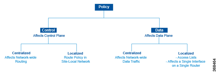
This topic offers an orientation about the architecture of the Cisco Catalyst SD-WAN policy used to implement overlay network-wide policies. These policies are called Cisco SD-WAN Validator policy or centralized policy, because you configure them centrally on a Cisco SD-WAN Controller. Cisco SD-WAN Controller policy affects the flow of both control plane traffic (routing updates carried by Overlay Management Protocol (OMP) and used by the Cisco SD-WAN Controllers to determine the topology and status of the overlay network) and data plane traffic (data traffic that travels between the Cisco IOS XE Catalyst SD-WAN devices across the overlay network).
With Cisco Catalyst SD-WAN, you can also create routing policies on the Cisco IOS XE Catalyst SD-WAN devices. These policies are simply traditional routing policies that are associated with routing protocol (BGP or OSPF) locally on the devices. You use them in the traditional sense for controlling BGP and OSPF, for example, to affect the exchange of route information, to set route attributes, and to influence path selection.
Centralized Control Policy Architecture
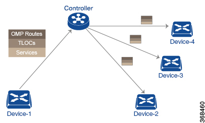
In the Cisco IOS XE Catalyst SD-WAN network architecture, centralized control policy is handled by the Cisco SD-WAN Controller, which effectively is the routing engine of the network. The Cisco SD-WAN Controller is the centralized manager of network-wide routes, maintaining a primary route table for these routes. The Cisco SD-WAN Controller builds its route table based on the route information advertised by the Cisco IOS XE Catalyst SD-WAN devices in its domain, using these routes to discover the network topology and to determine the best paths to network destinations. The Cisco SD-WAN Controller distributes route information from its route table to the devices in its domain which in turn use these routes to forward data traffic through the network. The result of this architecture is that networking-wide routing decisions and routing policy are orchestrated by a central authority instead of being implemented hop by hop, by the devices in the network.
Centralized control policy allows you to influence the network routes advertised by the Cisco SD-WAN Controllers. This type of policy, which is provisioned centrally on the Cisco SD-WAN Controller, affects both the route information that the Cisco SD-WAN Controller stores in its primary route table and the route information that it distributes to the devices.
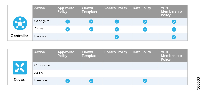
Centralized control policy is provisioned and applied only on the Cisco SD-WAN Controller. The control policy configuration itself is never pushed to devices in the overlay network. What is pushed to the devices, using the Overlay Management Protocol (OMP), are the results of the control policy, which the devices then install in their local route tables and use for forwarding data traffic. This design means that the distribution of network-wide routes is always administered centrally, using policies designed by network administrators. These policies are always implemented by centralized Cisco SD-WAN Controllers, which are responsible for orchestrating the routing decisions in the Cisco IOS XE Catalyst SD-WAN overlay network.

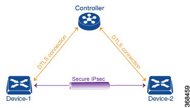
All centralized control plane traffic, including route information, is carried by OMP peering sessions that run within the secure, permanent DTLS connections between devices and the Cisco SD-WAN Controllers in their domain. The end points of an OMP peering session are identified by the system IDs of the devices, and the peering sessions carry the site ID, which identifies the site in which the device is located. A DTLS connection and the OMP session running over it remain active as long as the two peers are operational.
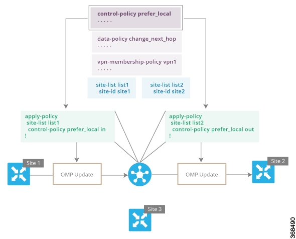
Control policy can be applied both inbound, to the route advertisements that the Cisco SD-WAN Controller receives from the devices, and outbound, to advertisements that it sends to them. Inbound policy controls which routes and route information are installed in the local routing database on the Cisco SD-WAN Controller, and whether this information is installed as-is or is modified. Outbound control policy is applied after a route is retrieved from the routing database, but before a Cisco SD-WAN Controller advertises it, and affects whether the route information is advertised as-is or is modified.
Route Types
The Cisco SD-WAN Controller learns the network topology from OMP routes, which are Cisco IOS XE Catalyst SD-WAN-specific routes carried by OMP. There are three types of OMP routes:
-
Cisco IOS XE Catalyst SD-WAN OMP routes—These routes carry prefix information that the devices learn from the routing protocols running on its local network, including routes learned from BGP and OSPF, as well as direct, connected, and static routes. OMP advertises OMP routes to the Cisco SD-WAN Controller by means of an OMP route SAFI (Subsequent Address Family Identifier). These routes are commonly simply called OMP routes.
-
TLOC routes—These routes carry properties associated with transport locations, which are the physical points at which the devices connect to the WAN or the transport network. Properties that identify a TLOC include the IP address of the WAN interface and a color that identifies a particular traffic flow. OMP advertises TLOC routes using a TLOC SAFI.
-
Service routes—These routes identify network services, such as firewalls and IDPs, that are available on the local-site network to which the devices are connected. OMP advertises these routes using a service SAFI.
The difference in these three types of routes can be viewed by using the various show sdwan omp operational commands when you are logged in to the CLI on a Cisco SD-WAN Controller or a Cisco IOS XE Catalyst SD-WAN device. The show sdwan omp routes command displays information sorted by prefix, the show sdwan omp services command displays route information sorted by service, and the show sdwan omp tlocs command sorts route information by TLOC.
Default Behavior Without Centralized Control Policy
By default, no centralized control policy is provisioned on the Cisco SD-WAN Controller. This results in the following route advertisement and redistribution behavior within a domain:
-
All Cisco IOS XE Catalyst SD-WAN devices redistribute all the route-related prefixes that they learn from their site-local network to the Cisco SD-WAN Controller. This route information is carried by OMP route advertisements that are sent over the DTLS connection between the devices and the Cisco SD-WAN Controller. If a domain contains multiple Cisco SD-WAN Controllers, the devices send all OMP route advertisements to all the controllers.
-
All the devices send all TLOC routes to the Cisco SD-WAN Controller or controllers in their domain, using OMP.
-
All the devices send all service routes to advertise any network services, such as firewalls and IDPs, that are available at the local site where the device is located. Again, these are carried by OMP.
-
The Cisco SD-WAN Controller accepts all the OMP, TLOC, and service routes that it receives from all the devices in its domain, storing the information in its route table. The Cisco SD-WAN Controller tracks which OMP routes, TLOCs, and services belong to which VPNs. The Cisco SD-WAN Controller uses all the routes to develop a topology map of the network and to determine routing paths for data traffic through the overlay network.
-
The Cisco SD-WAN Controller redistributes all information learned from the OMP, TLOC, and service routes in a particular VPN to all the devices in the same VPN.
-
The devices regularly send route updates to the Cisco SD-WAN Controller.
-
The Cisco SD-WAN Controller recalculates routing paths, updates its route table, and advertises new and changed routing information to all the devices.
Behavior Changes with Centralized Control Policy
When you do not want to redistribute all route information to all Cisco IOS XE Catalyst SD-WAN devices in a domain, or when you want to modify the route information that is stored in the Cisco Catalyst SD-WAN Controller's route table or that is advertised by the Cisco Catalyst SD-WAN Controller, you design and provision a centralized control policy. To activate the control policy, you apply it to specific sites in the overlay network in either the inbound or the outbound direction. The direction is with respect to the Cisco Catalyst SD-WAN Controller. All provisioning of centralized control policy is done on the Cisco Catalyst SD-WAN Controller.
Applying a centralized control policy in the inbound direction filters or modifies the routes being advertised by the Cisco IOS XE Catalyst SD-WAN device before they are placed in the route table on the Cisco Catalyst SD-WAN Controller. As the first step in the process, routes are either accepted or rejected. Accepted routes are installed in the route table on the Cisco Catalyst SD-WAN Controller either as received or as modified by the control policy. Routes that are rejected by a control policy are silently discarded.
Applying a control policy in outbound direction filters or modifies the routes that the Cisco Catalyst SD-WAN Controller redistributes to the Cisco IOS XE Catalyst SD-WAN devices. As the first step of an outbound policy, routes are either accepted or rejected. For accepted routes, centralized control policy can modify the routes before they are distributed by the Cisco Catalyst SD-WAN Controller. Routes that are rejected by an outbound policy are not advertised.
VPN Membership Policy
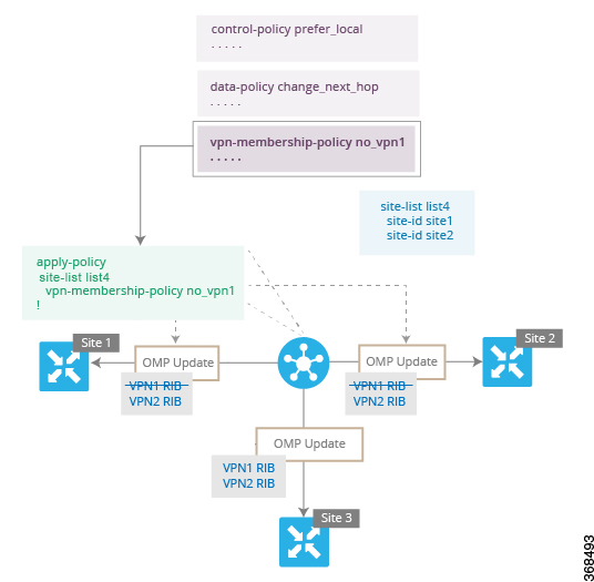
A second type of centralized data policy is VPN membership policy. It controls whether a Cisco IOS XE Catalyst SD-WAN device can participate in a particular VPN. VPN membership policy defines which VPNs of a device is allowed and which is not allowed to receive routes from.
VPN membership policy can be centralized, because it affects only the packet headers and has no impact on the choice of interface that a Cisco IOS XE Catalyst SD-WAN device uses to transmit traffic. What happens instead is that if, because of a VPN membership policy, a device is not allowed to receive routes for a particular VPN, the Cisco Catalyst SD-WAN Controller never forwards those routes to that driver.
Examples of Modifying Traffic Flow with Centralized Control Policy
This section provides some basic examples of how you can use centralized control policies to modify the flow of data traffic through the overlay network.
Create an Arbitrary Topology
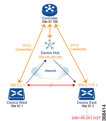
One way to minimize this overhead is to create a hub-and-spoke type of topology in which one of the devices acts as a hub site that receives the data traffic from all the spoke, or branch, devices and then redirects the traffic to the proper destination. This example shows one of the ways to create such a hub-and-spoke topology, which is to create a control policy that changes the address of the TLOC associated with the destination.
The figure illustrates how such a policy might work. The topology has two branch locations, West and East. When no control policy is provisioned, these two devices exchange data traffic with each other directly by creating an IPsec tunnel between them (shown by the red line). Here, the route table on the Device West contains a route to Device East with a destination TLOC of 203.0.113.1, color gold (which we write as the tuple {192.0.2.1, gold}), and Device East route table has a route to the West branch with a destination TLOC of {203.0.113.1, gold}.
To set up a hub-and-spoke–type topology here, we provision a control policy that causes the West and East devices to send all data packets destined for the other device to the hub device. (Remember that because control policy is always centralized, you provision it on the Cisco Catalyst SD-WAN Controller.) On the Device West, the policy simply changes the destination TLOC from {203.0.113.1, gold} to {209.165.200.225, gold}, which is the TLOC of the hub device, and on the Device East, the policy changes the destination TLOC from {192.0.2.1, gold} to the hub's TLOC, {209.165.200.225, gold}. If there were other branch sites on the west and east sides of the network that exchange data traffic, you could apply these same two control policies to have them redirect all their data traffic through the hub.
Set Up Traffic Engineering
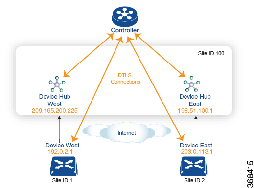
The figure shows that Site ID 100 has two hub devices, one that serves the West side of the network and a second that serves the East side. Data traffic from the Device West must be handled by the Device West hub, and similarly, data traffic from the Device East branch must go through the Device East hub.
To engineer this traffic flow, you provision two control policies, one for Site ID 1, where the Device West device is located, and a second one for Site ID 2. The control policy for Site ID 1 changes the TLOC for traffic destined to the Device East to {209.165.200.225, gold}, and the control policy for Site ID 2 changes the TLOC for traffic destined for Site ID 1 to {198.51.100.1, gold}. One additional effect of this traffic engineering policy is that it load-balances the traffic traveling through the two hub devices.
With such a traffic engineering policy, a route from the source device to the destination device is installed in the local route table, and traffic is sent to the destination regardless of whether the path between the source and destination devices is available. Enabling end-to-end tracking of the path to the ultimate destination allows the Cisco Catalyst SD-WAN Controller to monitor the path from the source to the destination, and to inform the source device when that path is not available. The source device can then modify or remove the path from its route table.
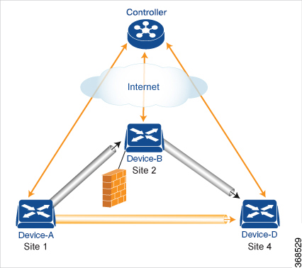
As part of end-to-end path tracking, you can specify how to forwarded traffic from the source to the ultimate destination using an intermediate device. The default method is strict forwarding, where traffic is always sent from Device-A to Device-B, regardless of whether Device-B has a direct path to Device-D or whether the tunnel between Device-B and Device-D is up. More flexible methods forward some or all traffic directly from Device-A to Device-D. You can also set up a second intermediate device to provide a redundant path with the first intermediate device is unreachable and use an ECMP method to forward traffic between the two. The figure Traffic Engineering3 adds Device-C as a redundant intermediate device.

Centralized control policy, which you configure on Cisco Catalyst SD-WAN Controllers, affects routing policy based on information in OMP routes and OMP TLOCs.
In domains with multiple Cisco Catalyst SD-WAN Controllers, all the controllers must have the same centralized control policy configuration to ensure that routing within the overlay network remains stable and predictable.
Configure Centralized Policy Based on Prefixes and IP Headers
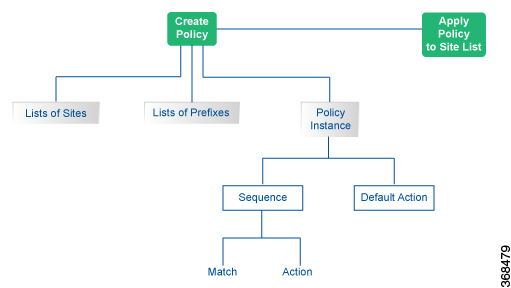
A centralized data policy based on source and destination prefixes and on headers in IP packets consists of a series of numbered (ordered) sequences of match-action pair that are evaluated in order, from lowest sequence number to highest sequence number. When a packet matches one of the match conditions, the associated action is taken and policy evaluation on that packets stops. Keep this in mind as you design your policies to ensure that the desired actions are taken on the items subject to policy.
If a packet matches no parameters in any of the sequences in the policy configuration, it is dropped and discarded by default.
Configuration Components
The following figure illustrates the configuration components for a centralized data policy:



 Feedback