Service Insertion

Table 1. Feature History

Feature Name

Release Information

Description

Service Insertion Using Workflows

Cisco IOS XE Catalyst SD-WAN Release 17.13.1a

Cisco Catalyst SD-WAN Manager Release 20.13.1

With this feature, you can create a service chain from the Workflow Library and configure a service chain action for a policy. A service chain inserts a set of services in the flow of traffic and can be designed to affect traffic according to your needs.

Trusted and Untrusted Postures

Cisco IOS XE Catalyst SD-WAN Release 17.14.1a

Cisco Catalyst SD-WAN Manager Release 20.14.1

With this feature, you can configure trusted traffic to flow to a trusted high availability pair in a service chain.

Information About Service Insertion

Service insertion, also known as service chaining, refers to placing one or more network or security services into the path of specific data traffic within the Cisco Catalyst SD-WAN overlay fabric. These services are defined in a service chain, which is a set of services that traffic routes through. The traffic is routed according to service chain actions that you configure for a data policy.

A service chain can be in any device, and can be used in any topology, including full mesh, hub-spoke, and Cisco Catalyst SD-WAN Multi-Region Fabric (MRF).

Cisco Catalyst SD-WAN service chaining is flexible, fully automated, and can be deployed on a per VPN basis. Service chaining includes the following key feature:

  • Service chaining can be used for overlay, local ingress and egress, inter- and intra-VPN, transit, branch-to-branch, branch-to-internet, branch-to-cloud, and cloud-to-cloud traffic

  • Automatic forwarding of traffic through all services in a chain

  • Services attachment methods of IPv4, IPv6, dual stack, and tunneled

  • Configurable high availability across instances of a single service

  • Built-in load balancing across instances of a single service, which supports equal cost multipath routing (ECMP) across high availability pairs

  • Advanced service tracking

  • Service chain sharing across multiple user VPNs, which can be different or the same as user traffic VPNS

  • Traffic steering methods using control policy, data policy, interface ACL, and supported match conditions

  • Fall back and restrict behavior

  • Path preference and symmetric routing

  • Security services to and from service transports

  • Trusted and untrusted high availability pairs and traffic marking (from Cisco Catalyst SD-WAN Manager Release 20.14.1)

  • Periodic on demand state notifications for serviceability

  • Cisco Catalyst SD-WAN Manager orchestration: Workflow based service chaining and traffic policy configuration

Service Insertion Capabilities

The following table provides information about the capabilities of the service chaining feature in releases before and afterCisco Catalyst SD-WAN Manager Release 20.13.1.

Capability

Releases Before Cisco Cisco Catalyst SD-WAN Manager Release 20.13.1

Releases From CiscoCisco Catalyst SD-WAN Manager Release 20.13.1

Multiple services in a chain

No native support

Native support

Traffic steering

Control policy

Control policy, data policy, interface ACL

Policy binding

Remote

Remote and local

Traffic type

IPv4

IPv4, IPv6, dual stack, tunnel

Load balancing

Across 4 IP addresses that serve as service endpoints

Across 4 instances of active-backup pairs for every traffic type

High availability

As provided by load balancing

Active and backup pairs

Tracking

To one connection per service instance

To every connection toward an abstract service

Configurable tracker probes

Not supported

All trackers are individually configurable

Behind-the-service tracking

Not supported

Supported

Affinity (service routes and data policy)

Not supported

Supported

TLOC preference

Supported

Supported

Fall back, restrict

Not supported

Supported

Tunnel connected services

Not supported

Supported

Shared service VPN

Not supported

Supported

To and from service transports

Not supported

Supported

Trusted and untrusted postures

Not supported

Supported from Cisco Catalyst SD-WAN Manager Release 20.14.1

Periodic and on-demand serviceability

Not supported

Supported

Cisco Catalyst SD-WAN Manager orchestration

Uses feature templates

Uses the Workflow Library and configuration groups (feature templates are not supported)

Deployment

On premises

On premises, cloud, middle mile colocated

Service instance type

Physical

Physical or virtual

Service Insertion Key Concepts and Implementation

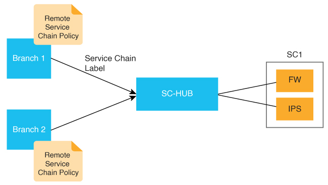
The following figure illustrates the basic concepts of service chaining and the general steps involved in service chain creation and execution.

Figure 1. Service Insertion Concepts and Steps

1

Services bring up:

  • Bring up and connect services to the Cisco Catalyst SD-WAN routers.

  • Use Cisco Catalyst SD-WAN Manager to bring up desired services.

2

Service chain configuration and advertising:

  • Use the Workflow Library or CLI commands to configure a service chain for routers, shown as SC1

  • Use a configuration group to configure SC-HUB1. The Workflow Library configuration adds auto-generated service chain configuration to the Service VPN part of the configuration group base on your inputs.

  • SC-HUB advertises the service chain to the Cisco SD-WAN Controller

3

Service chain policy:

  • Match traffic or routes and perform service chain actions

  • Apply a service chain policy to sites where traffic originates

  • The Cisco SD-WAN Controller resolves and advertises the service chain to target sites

4

Traffic steering:

  • Traffic is steered from the source (B1) to SC-HUB

  • The first service in the service chain is executed

  • Traffic returns to SC-HUB from the first service

  • The second service in the service chain is executed

  • Traffic returns to SC-HUB from the second service

  • Traffic is forwarded to the destination (B2)

The following figure illustrates the key elements in service insertion. In this figure, SC-HUB1 is the router to which the service chain is attached.

In the hairpin model, traffic is sent by SC-HUB1 to a service in the service chain, and the service returns the traffic to SC-HUB1. SC-HUB1 then either forwards the traffic to the next service in the service chain or to the destination if the traffic is returning from the last service in the service chain.

In the exit Model, traffic is sent by SC-HUB1 to a service in a service chain, and the service forwards the traffic to the destination. Traffic may return from the destination to the service, which returns it to SC-HUB1.
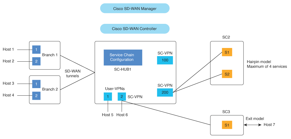
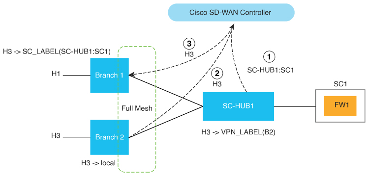
Figure 2. Service Insertion Key Elements

Restrictions for Service Insertion

  • A service chain can include up to four service types. Each service type can have multiple instances of the service, either as high availability pairs that are load-balanced by the feature, or behind a third-party load balancer.

  • The services in a service chain must be in a single VPN.

  • If you are using a dual stack service in a service chain, every service in that service chain must have a dual stack high-availability pair.

  • A specific device interface should not be used for more than one service in a particular service chain.

  • A specific interface can be used in different service chains only if it is used for the same service type in each of the service chains.

  • All the interfaces and tunnels for the services in a service chain should be part of the VPN in which the service chain is defined.

  • More than one tracker should not be associated with a given interface. For example, if endpoint-tracker tracker1 is associated with GigabitEthernet1, a different tracker cannot be associated with GigabitEthernet1.

Use Cases for Service Insertion

  • Service chaining can be used when traffic from a less secure region of a network should pass through a firewall to ensure that it has not been tampered with.

  • Service chaining can be used in a network that consists of multiple VPNs, where each represents a different function or organization, to ensure that traffic between VPNs flows through a firewall. For example, in a campus, interdepartmental traffic might go through a firewall, while intradepartmental traffic might be routed directly.

  • Service chaining can be used to ensure regulatory compliance, such as Payment Card Industry Data Security Standard (PCI DSS), where PCI traffic should flow through firewalls in a centralized data center or regional hub.

Configure Service Insertion

Beginning with Cisco Catalyst SD-WAN Manager Release 20.13.1, you can configure service insertion by using the Workflow Library. From the Workflow Library, you can create a new service chain or modify an existing one. A service chain can contain up to four service types.

The workflow guides you through configuring several steps, including:

  • Configuring the name and description of the service chain

  • Specifying the services in the service chain and the order of the services in the chain

  • Provide attachment parameters for the services in the chain, which are used when you attach the service chain to routers

  • For each service type, specify the VPN and configure options such as load balancing, high availability and tracking

To create or modify a service chain:

  1. From the Cisco SD-WAN Manager menu, choose Workflows > Workflow Library.

  2. Click Define and Configure Service Chain.

  3. Follow the prompts in the workflow.

    Ensure that you define a tacker. Tracker configuration is critical to avoid blackhauling. Defining a tracker ensures that the service chain is determined to be in the UP state and is used. If the IP address of a service chain firewall is used with an ICMP-based tracker, ensure that the firewall allows ICMP on the appropriate interface.

    Ensure that the service chain can route returning traffic back into the Cisco Catalyst SD-WAN fabric. To do so, use dynamic routing protocols between the service chain and Cisco Catalyst SD-WAN router (service chain hub) or use static routes.

    Attach the service chain to the appropriate Cisco Catalyst SD-WAN SC-Hub router. The service chain does not need to be attached to branch routers.

After you configure service insertion, perform the following actions as needed:

Configure Service Chain Actions in a Data Policy

Beginning with Cisco Catalyst SD-WAN Manager Release 20.13.1, you can route traffic through a service chain by configuring service chain actions for a data policy.

  1. From the Cisco SD-WAN Manager menu, choose Configuration > Policies.

  2. Click Custom Options then click Traffic Policy under Centralized Policy.

  3. Click the Traffic Data tab.

  4. Click Add Policy and click Create New.

  5. Click Sequence Type and choose Service Chaining from the Add Data Policy dialog box.

  6. Click the Actions tab.

  7. Click Service.

  8. Configure the fields that the following table describes.

    Table 2. Service Chain Action Fields

    Field

    Description

    Service: Type

    Choose a type of service for the service chain.

    Service: VPN

    VPN in which the service chain is hosted.

    Range: 0 through 65530

    Service: TLOC IP

    Enter the IP address of the Transport Locator (TLOC) for applying the services in the service chain.

    Color

    Choose a color for the TLOC.

    Encapsulation

    Choose the encapsulation type for the TLOC.

    Service: TLOC List

    Choose a predefined TLOC list to use for applying services to branch traffic.

    Local

    Check the Local check box if the service chain is hosted locally.

    If you do not check this check box, the service chain is hosted remotely.

    Restrict

    Check this option to cause packets to be dropped if the service chain goes down. f you configure this policy with the Local option, packets are dropped locally. If you configure this policy with the Remote option, packets are dropped on the remote host.

    This option is unchecked by default (traffic falls back to routing).

Traffic Steering to a Service Chain

You can direct traffic to a service chain by using a control policy, data policy, or interface access control list.

Traffic Steering Using a Control Policy

You can use a control policy to modify Cisco Overlay Management Routes, also referred to as vRoutes, to direct traffic to a service chain instead of the original destination.

The following figure shows an example of the use of a control policy to direct traffic to a service chain.

In this example, the policy causes service chain 1 (SC1) to be applied to traffic that flows between H1 (host 1) and H3 (host 3). The policy sets SC1 as the next hop for H1 and H3 traffic routes. Before the policy is in effect, traffic flows from B2 (branch 2) to B1 (branch 1). After the policy is in effect, traffic flows from B2 to SC-HUB1:SC1 to B1.

Figure 3. Traffic Steering with a Control Policy

1

SC-HUB1 advertises the SC1 route

2

B2 advertises the H3 route to the Cisco SD-WAN Controller

3

The control policy results in overriding the H3 route next hop to SC1 and the Cisco SD-WAN Controller advertises the H3 route to B1

Example configuration:

Control-policy name
    sequence number
        match route
        action accept
	  set service-chain sc_name [tloc|tloc-list name] [vpn vpn]
apply-policy site-list site_list control-policy name out

Traffic Steering Using a Data Policy

You can use a data policy to match traffic and operate in the context of source VPNs during forwarding.

The following figure shows an example of the use of a data policy to specify service chaining intent in a remote branch.

Figure 4. Traffic Steering with Traffic Service Chaining Intent Specified at a Remote Branch

The following example shows configuration for traffic steering with a data policy when traffic intent is specified on a remote device. In this example:

  • match criteria specifies applications to be matched to source and destination IP address combinations

  • restrict|fallback configures restrict or fall back

  • tloc|tloc-list list specifies the traffic path preference using TLOC ranking


Note


set attribute trust-posture is available from Cisco Catalyst SD-WAN Manager Release 20.14.1.
policy
 data-policy name
  vpn-list name
   sequence 100
    match criteria
    action accept
     set service-chain sc_name vpn vpn {restrict|fallback} [tloc|tloc-list list]
set attribute trust-posture {trusted | untrusted}
apply-policy site-list remote-sites data-policy name from-service

The following figure shows an example of the use of a data policy to specify the service chaining intent locally in the device to which the service chain is attached.

Figure 5. Traffic Steering with Traffic Service Chaining Intent Specified on a Local Device

The following example shows configuration for service chaining intent on a local device. In this example, local indicates that traffic needs to be directed to a service chain locally.

set service-chain SC1 [vpn vpn] local [restrict|fallback]
apply-policy site-list SC-HUB-sites data-policy policy {from-service|from tunnel}|from-tunnel}

Traffic Steering Using an Interface Access Control List

You can use an interface access control list (ACL) to service chain traffic that is incoming or outgoing on a specified interface. In some situations, the traffic forwarding decision may need to come from a prior routing lookup or data policy.

This approach is useful when all traffic from an interface should be directed through a service chain.

The following figure shows an example of the use of am an ACL to direct traffic through a service chain.

Figure 6. Traffic Steering with an ACL

The following example shows configuration for traffic steering using an ACL.

access-list list
  sequence number
    match criteria
    action accept
     set service-chain SC1 [vpn vpn] {restrict|fallback}
interface interface 
 access-list list {in|out}

Path Preference

You can use TLOC preference or affinity preference to choose the preferred path for traffic to a service chain.

To do so, configure a TLOC list to direct traffic only over certain TLOCs or to prefer certain TLOCs over others. The TLOC list can be specified with tloc-list as part of a service chain action in a data policy or a control policy.

To configure affinity preference, use affinity-group preference in branch sites to set the affinities of branches, and use affinity-group in service chain hubs to set the affinities of VPNs. The data policy set service chain action is compliant with affinity by default.

You can configure the following command to disable consideration of affinity in a data policy:

data-policy-ignore-affinity-metric

If both TLOC preference and affinity preference are configured, the affinity preference is evaluated first, then the TLOC preference is evaluated.

Share Service Chains Across User VPN

A service chain VPN can be shared across multiple user VPNs, and traffic between VPNs can be serviced chained in any VPN. Sharing a service chain does not require additional configuration. If source and destination VPNs are different, route leaking is required between the source and destination VPN.

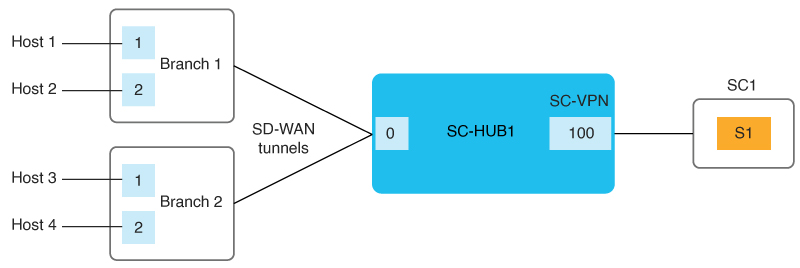
The following figure illustrates the sharing of service chains across user VPNs. In this figure:

  • SC1 (service chain 1) is attached to VPN100 can be automatically shared by traffic in VPN1 (H1) and VPN2 (H4)

  • Traffic between VPN1 (H1) and VPN2 (H4) can be service chained in VPN1 or VPN2 or in a shared service chain (VPN100)

Figure 7. Service Chain Sharing Across VPNs

Separate Interfaces for Transmitted and Received Traffic

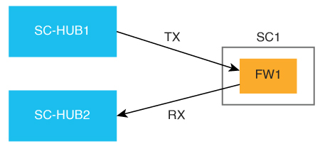
You can use the service command to configure separate interfaces for transmitted and received traffic through a service chain. In this situation, transmitted and received traffic are tracked independently. For more information, see service.

The following figure illustrates this approach.

Figure 8. Separate Interfaces for Transmitted and Received Traffic

Service Chaining Trusted and Untrusted Traffic

Minimum supported releases: Cisco IOS XE Catalyst SD-WAN Release 17.14.1a, Cisco Catalyst SD-WAN Manager Release 20.14.1

You can configure trusted traffic to flow to a trusted high availability pair. In this situation, untrusted traffic flows to an untrusted high availability pair.

Use the set attribute trust-posture untrusted action in data policy to mark a packet as trusted or untrusted. The default trust-posture of a packet is trusted.

The following figure illustrates the flow of trusted and untrusted traffic.

Figure 9. Trusted and Untrusted Traffic

Example configuration:

service-chain SC1
    service netsvc1
        sequence 10
        service-transport-ha-pair 1
            attribute trust-posture {trusted|untrusted}

Service Chain Between Two Routers

If the router that is transmitting traffic to a service chain is different from the router that is receiving traffic from the service chain, configure the same service chain in each device. The service chain can have only one service and is for intra-VPN traffic only.

The following figure illustrates this approach.

Figure 10. Service Chain Between Two Router

Configure Fall Back and Restrict Behavior for Traffic Through a Service Chain

You can configure fall back or restrict behavior for traffic that travels through a service chain.

When fallback is configured in the set service-chain action, traffic falls back to routing if a service chain goes down or if the TLOCs that are specified in a policy are not available.

When restrict is configured in the set service-chain action, packets are dropped if a service chain goes down or if the TLOCs that are specified in a policy are not available. The restrict behavior is suitable for security services such as a firewall.

Fall back and restrict can be specified in a centralized data policy (remote or collocated) and an interface ACL.


Note


If an egress ACL is used to direct traffic to a service chain, all packets continue to the destination even if the restrict behavior is configured because the forwarding decision is made before the state of the service chain is detected.

Interfaces for Attaching Services in a Service Chain to a Router

The services in a service chain must be in a single VPN, called a service chain VPN, or SC-VPN.

The services in a service chain can be attached to a Cisco Catalyst SD-WAN router through any combination of an IPv4, IPv6, dual stack, or tunnel interface.

The following figure illustrates the interfaces for attaching services in a service chain to a router.

Figure 11. Attaching Services to a Router

1

IPv4 attachment

2

IPv6 attachment

3

Dual stack attachment

4

Tunnel attachment

Service Chaining with Software Defined Cloud Interconnect Bring Your Own Service

The Software Defined Cloud Interconnect (SDCI) establishes connections between branch sites and the cloud through network service providers, including Megaport and Equinix. The SDCI bring your own service (BYOS) functionality establishes a centralized location for service inspection by connecting a service chain to the Cisco Catalyst 8000v Edge Software (Catalyst 8000v) SDCI gateways that are deployed in the middle mile network. BYOS enables the seamless integration of external services with the SDCI infrastructure. Colocated data policies, also known as centralized data policies, are enforced on these gateways within the middle mile network for selective data traffic inspection.

In this context, a branch site represents the first mile, a service provider acts as the middle mile, and the cloud serves as the last mile.

The BYOS service inspection for SDCI allows service chaining in the following situations:

  • Connecting branch sites to cloud workloads through middle mile providers using the C8000v SDCI gateway.

  • Interconnecting branch site through the middle mile provider using the Catalyst 8000v SDCI gateway.

  • Facilitating intercloud traffic connectivity by the middle mile provider through the Catalyst 8000v SDCI gateway.

Configure Service Insertion Using a CLI Template

For more information about using CLI templates, see CLI Add-On Feature Templates and CLI Templates.


Note


By default, CLI templates execute commands in global config mode.

The section provides a sample CLI configuration for service insertion.

  1. Create a service chain:

    service-chain chain-number
  2. Configure a description for the service chain:

    service-chain-description description
  3. Specify the services that are in the service chain and configure related options:

    service service-type service-parameters
  4. (Optional, from Cisco Catalyst SD-WAN Manager Release 20.14.1) Configure the trust posture for the services that are in the service chain:

    service service-type service-transport-ha-pair value attribute trust-posture {trusted | untrusted}
  5. (Optional) Configure all Cisco Catalyst SD-WAN bidirectional forwarding (BFD) sessions to be brought down:

    service-chain-affect-bfd
  6. Specify the name of the VPN that hosts all services in the service chain:

    service-chain-vrf vrf
  7. (Optional, enabled by default) Enable endpoint tracking for services in the service chain:

    track-enable
  8. (Optional, enabled by default) Enable the service chain, which makes it active on devices:

    service-chain-enable