Mounting the Router

This chapter describes the safety information, equipment, and procedures required to mount the IR8140H router on a vertical pole or streetlight.

These topics are discussed:

Mounting Kits Overview

You will need some or all of the kits described in this section to install the router on a pole. Your installation environment and requirements determine the kits you need.

For a detailed description of each kit, see Contents of the Mounting Kits.

Cisco Product ID (PID)

Name

Description

Mounting Bracket Kit

Use this kit if your installation requires a Cisco mounting bracket to mount the router. This kit is included in the router accessory kit, and is used with the pole kit, and includes the hardware required to attach the mounting bracket to the mounting plate.

IR-PMK1000

Pole Mount Kit

This kit is required for all pole or streetlight installations, and includes a mounting plate and the hardware required to attach the mounting plate to a pole. This kit includes the two steel straps of IR-PMK_BAND as well.

IR-PMK-BAND

Band Strap Kit

This kit includes two steel straps for mounting the router on poles larger than 4.5 inches (11.4 cm) in diameter. This kit is used together with the pole mount kit (Pole Mount Kit). A BAND-IT tool is required to install the steel straps on a pole.

AIR-BAND-INST-TL=

Strap Tool Kit

This kit includes a BAND-IT tool that is required when using steel straps to install the router on poles larger than 4.5 inches (11.4 cm) in diameter.

General Safety Information for Mounting

Read the safety warnings in this section.

One person is required to properly and safely mount the router.


Note


All mounting methods at any location are subject to the acceptance of local jurisdiction.


Note


The mounting surface, attaching screws, and optional wall anchors must be able to support a 50 pound (22.7 kg) static weight.


Note


Personnel mounting the router must understand grounding methods.


Warning


Do not locate the antenna near overhead power lines or other electric light or power circuits, or where it can come into contact with such circuits. When installing the antenna, take extreme care not to come into contact with such circuits, as they may cause serious injury or death. For proper installation and grounding of the antenna, please refer to national and local codes (for example, U.S.:NFPA 70, National Electrical Code, Article 810, Canada: Canadian Electrical Code, Section 54). Statement 1052


Contents of the Mounting Kits

This section describes the contents of the mounting kits available for the router, and when you should use each kit.

Pole Mount Kit

Use the Cisco pole mount kit to install the mounting plate on any pole or streetlight. The kit supports poles that meet the following criteria:

  • Size: 2 to 16-inch diameter poles

  • Material: Metal, wood, or fiberglass poles

Figure 1. Pole Mount Kit Contents

Item

Name

Qty.

Description

1

Mounting plate

1

Install mounting plate on pole. Mounting bracket attaches to the mounting plate.

2

Clamp brackets

2

Use the clamp brackets to install the mounting plate on a pole of up to 4.5 inches in diameter.

Included Hardware

3

Washer (3/8 inch)

4

Use the included hardware to attach the mounting plate to the pole, as described in Installing the Mounting Plate On To a Pole.

4

Split lock washer (3/8 inch)

4

5

Nut (3/8-16)

4

6

Carriage bolt (3/8-16 x 7 inches)

4

Mounting Bracket Kit

Use the mounting bracket kit if you require a Cisco mounting bracket. The mounting bracket attaches to the mounting plate, and then the router is installed on the mounting bracket.

You can also use any compatible mounting bracket with the Cisco pole mount kit. Check with your authorized Cisco reseller for compatible mounting brackets. See Pole Mount Kit.

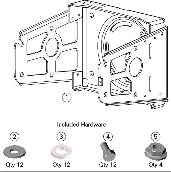
Figure 2. Mounting Bracket Kit Contents—Required Parts

Item

Name

Qty.

Description

1

Mounting bracket

1

Mounts router to the mounting plate or wall.

Included Hardware

2

Washer (M8)

12

Use the hardware specified in the figure above (items 2 through 5) to attach the mounting bracket to the mounting plate, and the router to the mounting bracket. Assemble the washer, split-lock washer, and bolt as described in Assemble Bracket Hardware.

3

Split lock washer (M8)

12

4

Bolt (M8 x 1.25)

12

5

Serrated nut (M8 x 1.25)

1

Use the nut to align the mounting bracket to the pole bracket when pole bracket is being used.

Band Strap Kit

Use the straps in the band strap kit when you mount the router on a pole larger than 4.5 inches (11.4 cm) in diameter. This installation also requires the pole mount kit and strap tool kit. See Pole Mount Kit and Strap Tool Kit.

Figure 3. Band Strap Kit Contents

Item

Description

1

Steel straps (2)

Strap Tool Kit

Use the tool in the strap tool kit to attach the steel straps that are included in the band strap kit. Steel straps are required to install the mounting plate on poles larger than 4.5 inches (11.4 cm) in diameter. See Band Strap Kit.


Note


The tool in the strap tool kit is manufactured and supported by BAND-IT.


Figure 4. Strap Tool Kit Contents

Item

Description

1

Strap tool

2

Strap tool documentation (not shown)

Materials and Tools You Must Have

  • 1/2-inch (13-mm) socket wrench

  • #2 Phillips head screwdriver

Mounting Instructions

This section includes all the procedures required to mount the router on any supported pole type.

Installing the Mounting Plate On To a Pole

This section describes three different procedures for installing the mounting plate on a pole. Follow the instructions provided for the pole type used in your installation.

The instructions in these sections refer to the mounting plate features shown in the following table.

Figure 5. Mounting Plate Details

Item

Description

Qty.

1

Carriage bolt holes

4

2

Bracket mount holes

8

3

Clearance holes, 3/4 in.

2

4

Pole clamp notches

2

5

Steel band strap slots

4

Install the Mounting Plate—Poles Up To 4.5 Inches in Diameter

Required Materials

  • Mounting plate, carriage bolts, and clamp brackets as described in Pole Mount Kit.

  • 13-mm box-end socket wrench

To install the mounting plate on a vertical pole up to 4.5 inches (11.4 cm) in diameter, perform this procedure.

Procedure

Step 1

Select a mounting location on the pole and place the top and bottom pole clamp bracket (1) notches against the pole.

Step 2

Place one of the clamp brackets on the opposite side of the pole, aligning the clamp bracket holes with the top two carriage bolt holes on the mounting plate.

Step 3

Insert a carriage bolt (5) through each of the top two carriage bolt holes on the mounting plate and through the holes in the clamp brackets.

Step 4

Position each bolt in the clamp so that the bolt is next to the pole, as shown in the following figure.

Step 5

To place the bracket hardware on each carriage bolt (see the following figure):

  1. Place the washer (2) and then the split lock washer (3) on the back of each carriage bolt (5).

  2. Thread the hex nut (4) on each carriage bolt. Ensure that the split-lock washer is between the washer and the nut.

    Figure 6. Carriage Bolt Hardware Assembly Details

Step 6

Hand tighten the hex nuts (do not over tighten).

Step 7

Repeat Step 3 through Step 6, installing the two bottom carriage bolts and the second clamp bracket at the bottom of the mounting plate.

Step 8

Position the mounting plate and clamp brackets on the pole, as needed, before tightening the carriage bolts further.

Step 9

Use a socket wrench to evenly tighten all four carriage bolts to finish installing the mounting plate on the pole.

Figure 7. Mounting Plate Installed on Pole with Clamp Brackets

Item

Description

1

Pole clamp notch

2

Carriage bolts (4)

3

Pole clamps (2)


Install the Mounting Plate—Poles Larger than 4.5 Inches in Diameter

Required Materials

To install the mounting plate on a vertical pole that is larger than 4.5 inches (11.4 cm) in diameter, perform the following procedure.

Figure 8. Mounting Plate Installed on Pole with Steel Straps for a Pole Greater than 4.5 Inch In Diameter
Procedure

Step 1

Assemble the straps and the mounting plate by threading the two steel straps through the band strap slots on the mounting plate.

Step 2

Select a mounting location on the pole.

Step 3

Position the mounting plate on the pole, as needed, and tighten the straps around the pole.

Step 4

Use the BAND-IT strap tool to tighten the metal bands around the pole, following the instructions in the box that is provided with the tool. Ensure that the metal bands are as tight as possible (approximately 7 ft lbs).

Note

 
When the metal bands are tightened to the full tension, the mounting plate cannot be adjusted unless the metal bands are disassembled or cut.

Install the Mounting Plate—Mounting on Wood Pole (Optional)

If the pole used in your installation is made of wood, you can optionally install the mounting plate using the procedure described in this section. This is an alternate mounting method to the following two mounting methods, which can also be used when mounting the router on a wood pole:

Required Materials

  • Mounting plate as described in Pole Mount Kit.

  • Hardware that you supply: 5/8-in. carriage bolt (length depends on the pole size in your installation), standard washer, fender washer, and nut (2 sets)

  • Tools that you supply: Drill, drill bit (for 5/8-in. through bolts), and 13-mm box-end socket wrench

To mount the router on a wood pole:

Procedure

Step 1

Place the mounting plate on the selected mounting location on the pole.

Step 2

Mark the drilling locations on the pole through the clearance holes and remove the mounting plate.

Step 3

Drill holes completely through the pole at the points you marked in Step 2.

Step 4

Position the mounting plate over the drilled holes. Align the clearance holes on the mounting plate with the drilled holes.

Step 5

Place a standard washer against one of the clearance holes on the mounting plate and then feed the bolt through the washer, clearance hole, and drilled hole. Push the bolt all the way through the pole. See Mounting Plate Details.

Step 6

Follow these steps on the opposite side of the pole:

  1. Place a fender washer at the end of the bolt, and then a nut.

  2. Hand tighten the nut.

Step 7

Repeat Step 5 and Step 6 for the second bolt.

Step 8

Use a socket wrench to evenly tighten both bolts to finish installing the mounting plate on the wooden pole (see the following figure).

Figure 9. Mounting Plate Installed on Wooden Pole with Through Bolts

Item

Description

1

5/8-in. through bolts (2)

2

Wood pole


Attach the Mounting Bracket to the Mounting Plate

This section describes how to attach the mounting bracket to the mounting plate.

Assemble Bracket Hardware

Several of the procedures in this section require you to assemble the bracket hardware before installing the bracket. A bracket hardware set consists of one bolt, one washer, one split-lock washer, and one nut.

To assemble the bracket hardware set, perform the following procedure.

Procedure

Step 1

Slide the split-lock washer (2) on the bolt (1), as shown in the following figure.

Figure 10. Assemble Bracket Hardware Set

Step 2

Slide the regular washer (3) on the bolt (1).

Ensure that the split-lock washer is between the regular washer and the bolt, as shown in the above figure.

The instructions for the procedures in this section make a reference to the mounting plate shown in the following figure.

Figure 11. Mounting Bracket Details

1

Pivot grooves (4)

2

Quick-hang notch

3

Quick-hang slots (2)

4

Optional wall-mount holes (4)

Note

 
The mounting plate must be installed as described in the section Installing the Mounting Plate On To a Pole.

Attach the Mounting Bracket

To attach the mounting bracket to the mounting plate, perform this procedure.

Figure 12. Mounting Bracket Attached to Mounting Plate

Required Materials

  • Mounting bracket and hardware as described in the Mounting Bracket Kit

  • 13-mm box-end socket wrench

Procedure

Step 1

Assemble six sets of bracket hardware (washer, split-lock washer, and bolt), as detailed in Assemble Bracket Hardware.

Step 2

Place the mounting bracket (6) against the mounting plate by inserting the bracket quick-hang notch (2) over the mounting plate quick-hang stud (5).

Step 3

Thread the serrated nut onto the quick-mount stud (4) and hand tighten (do not over tighten).

Step 4

Align the pivot grooves (7) on the bracket with four of the bracket-mount holes (1) on the mounting plate. Follow these guidelines:

  • Each of the four pivot grooves on the bracket must be attached to at least one bracket-mount hole on the mounting plate.

  • The final orientation of the mounting plate and router determine which bracket-mount holes are used.

  • Mount the router, as described in Installing the Mounting Plate On To a Pole.

Step 5

Insert one bolt assembly (3) through one of the pivot grooves (7) on the bracket and then through the corresponding bracket mount hole on the mounting plate.

Step 6

Repeat Step 5 for the remaining bolt assemblies.

Step 7

Position the mounting-bracket onto the mounting plate, as needed, before further tightening the bolts.

Step 8

Use a socket wrench to evenly tighten all four bolts and the serrated nut to finish installing the bracket on the plate. Use a torque of 6 to 7 foot-pounds when tightening the bolts and nut.


Attach the Router Onto the Mounting Bracket

This section describes how to attach the IR8140H to the mounting bracket.

Required materials:

  • 13-mm box-end socket wrench

  • Two sets of bracket hardware (split-lock washer, regular washer, and bolt). Attach each of the bracket sets to opposite sides of the IR8140H to provide support and enable it to rest on the bracket to each side of the router (see Assemble Bracket Hardware Set).

Procedure


Step 1

Attach two sets of bracket hardware, one on either side of the IR8140H router.

Step 2

Slide the router onto the bracket and rest it on the two quick-hang slots (see Mounting Bracket Details).

Step 3

Use a socket wrench to evenly tighten the two sets of bracket hardware to secure the router to the mounting bracket.

Figure 13. IR8140H Attached to the Mounting Bracket

Step 4

You are now ready to ground the router. See Grounding the Router.


Installing the Security Bracket on the Router

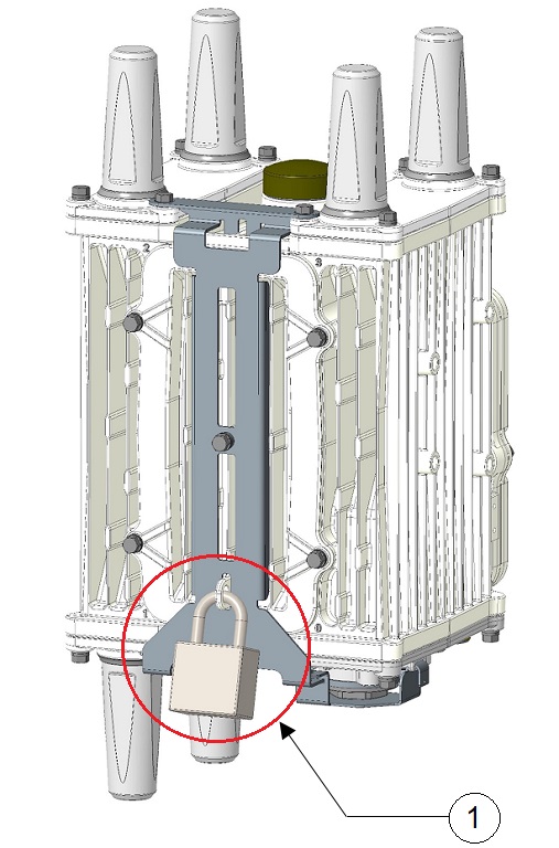
The security bracket is used to secure the CPU, UIMs, and BBU on the router with a padlock. (The padlock is not provided by Cisco.)

Follow these steps to install the security bracket.

Before you begin

Ensure all bolts and screws on the unit are tightened. Every module slot should have a module or a cover installed. Ensure the plastic CPU console port plug is installed and tight. This plug should be found on the bottom right side of the unit and should be screwed into the front-most hole on the bottom module.

Procedure


Step 1

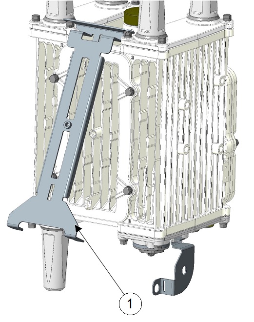
Hang the CPU security bracket (2) onto the slot (3) on the bottom of the chassis. When looking at the front of the chassis, the slot will be found at the bottom right of the chassis towards the front. Insert the U-shaped flange of the CPU security bracket into the slot from the inner side of the chassis, so that the opening of the U-shape comes out of the outside of the chassis. The CPU security bracket should be able to hang freely on the slot. See the following figure.

1

CPU console port plug

2

CPU security bracket

3

Slot on the bottom of the chassis to install the CPU security bracket

Step 2

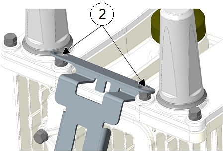
Hold the long front BBU security bracket (1) and attach it from the top of the chassis. It should be done at an angle in order to correctly mount the top two holes on the top screws. It should fit over the top two inner screws on each top module. Notice that the security bracket only fits in one direction. It is not symmetrical. There is a top and a bottom of the bracket.

The following figure shows the top two screws (2) to align the security bracket over and fit onto.

Step 3

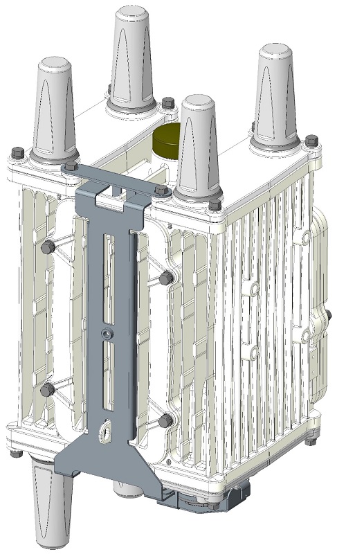
Once the bracket is seated over the top screws, slowly rotate the bracket closer to the front of the chassis. At the same time, one hand should be used to lift the bottom, circular, CPU bracket so that the slot in the CPU bracket lines up with the bottom right flange of the BBU bracket so that they click into place. This will ensure a safe mount of the CPU bracket. The flange on the CPU bracket should be seated above the flange of the front BBU security bracket.

1

BBU security bracket and CPU security bracket connecting together.

The following figure shows the mounted BBU security bracket and CPU security bracket.

Step 4

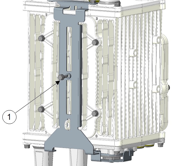
Use the M6 size bolt (1) included with the bracket to secure the bracket into place on the front of the chassis through the hole in the middle of the chassis front BBU cover. Torque to 15 to 20 in-lbs.

Step 5

Secure the BBU bracket and the unit with a padlock to the padlock tab on the front slot (1).


Grounding Instructions

In all installations, after the router is mounted, you must properly ground the unit according to the instructions in this section before connecting the router to the network and power.


Warning


This equipment must be externally grounded using a customer-supplied ground wire before power is applied. Contact the appropriate electrical inspection authority or an electrician if you are uncertain that suitable grounding is available. Statement 366


Warning


Installation of the equipment must comply with local and national electrical codes. Statement 1074


Grounding Hardware

The router is shipped with a grounding kit, as shown in the following figure.

Figure 14. Router Grounding Kit Contents

Item

Description

Qty.

1

Grounding lug

1

2

Screws

2

Grounding the Router

You can perform these steps when the IR8140H is attached onto the mounting bracket, as seen in IR8140H Attached to the Mounting Bracket.

To ground the router:

Procedure


Step 1

Use the appropriate crimping tool or pliers to crimp the 6-gauge ground wire (included in the grounding kit) to the grounding lug.

Step 2

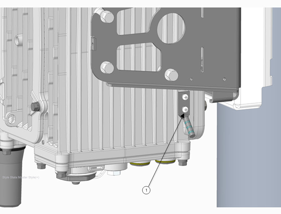
Connect the grounding lug to the router chassis ground connection point shown in Grounding Lug Connectors (Chassis Ground Connection Point) , using the supplied grounding screws.

Note


Tighten the grounding screws to 20-24 in-lbs of torque. Do not overtighten!

Step 3

If necessary, strip the other end of the ground wire and connect it to a reliable earth ground, such as a grounding rod or an appropriate grounding point on a pole that is grounded.

Figure 15. Grounding Lug Connectors (Chassis Ground Connection Point)

Item Number

Description

1

Ground lug and screws (qty. of 2) and 6-gauge ground wire