Installing Universal Interface Modules

This chapter discusses how the Cisco Catalyst IR8140 Heavy Duty Router supports up to three Universal Interface Modules (UIMs) that enable Neighborhood Area Network (NAN) connections from the router to field devices such as meters and Intelligent Electronic Devices (IEDs), and from the router to the central utility station or data management center.

These topics are discussed:

Installing or Replacing Modules

The router supports up to three UIMs. Depending on the configuration, your router could arrive in a shipping container with all required modules already installed. However, you need to install a module when you:

  • Add modules to your current installation.

  • Replace a faulty module.

Installing Modules in the Router

This section provides general instructions for installing modules in the router.

Preparing to Install Modules

Before installing modules in the router, ensure that the following guidelines have been met:

  • Verify that there is adequate airflow around the router. See Installation Safety and Site Preparation.

  • Make sure the router is powered off.

  • When modules are installed in a closed assembly (such as inside the router), the temperature around it might be higher than normal room temperature.

  • The installation environment humidity must not exceed 95 percent (noncondensing).

  • The installation site altitude must be no higher than 10,000 feet.

Installation Warning Statements

This section includes the installation warning statements. Translations of these warning statements appear in the Regulatory Compliance and Safety Information for Cisco Catalyst Industrial Router 8140 Heavy Duty Series Router documents on Cisco.com, at:

https://www.cisco.com/c/en/us/support/routers/catalyst-ir8100-heavy-duty-series-routers/series.html


Warning


Only trained and qualified personnel should be allowed to install, replace, or service this equipment. Statement 1030


Warning


To prevent the system from overheating, do not operate it in an area that exceeds the maximum recommended ambient temperature of 158°F (70°C). Statement 1047


Warning


To prevent airflow restriction, allow clearance around the router of 6" on vertical sides and 12" above and below.


Installing and Removing Modules

This section provides general module installation steps (for offline cases), and includes informatioin about additional documentation.

Tools and Materials You Supply

You must provide the following tool to install and remove modules:

  • 10-mm socket driver

Supported Modules

The following table shows the UIMs supported on IR8140H. For information about supported antennas in each module, see Selecting and Installing Antennas.

Table 1. Supported UIMs

Module Type

Module PID

Description

Cellular modules (LTE/5G)

IRMH-LTE-MNA

Multicarrier band-14 CAT4 LTE module for North America

IRMH-LTE-MNA-900

Multicarrier band-14 CAT4 LTE module for North America with 900-MHz WPAN coexistence filter

IRMH-LTEA-EA

CAT6 LTE advanced module for Europe and North America

IRMH-LTEA-EA-900

CAT6 LTE advanced module for Europe and North America with 900-MHz WPAN coexistence filter

IRMH-LTEA-LA

CAT6 LTE advanced module for APAC, LATAM, and ANZ

IRMH-LTEAP18-GL

CAT18 LTE advanced PRO module for ALL Global Regions

IRMH-5GS6-GL

5G Sub-6 GHz universal interface module for ALL Global Regions.

IRMH-5GS6-GL supports the same bands and frequencies as P-5GS6-GL PIM. For more information, see the following docuemntation:

WPAN modules

IRMH-WPAN-NA

IEEE 802.15.4e/g 900-MHz WPAN module for North America

IRMH-WPAN-BRZ

IEEE 802.15.4e/g 900-MHz WPAN module for Brazil

Module Installation Locations

To ensure support for all module types and allow convenient cabling, we recommend the following installation location guidelines:

Table 2. UIM Locations in the IR8140H Router

Installation Slot

UIM Type

Slot 1

WPAN module

Slot 2 or 3

Note


Installing WPAN module in slot 2 or 3 is supported from Cisco IOS XE Release 17.7.1.

WPAN module or Cellular module (4G/5G)

Note


For restrictions and guidance on installing a WPAN module in slots 2 or 3, see Recommended Module Installation Scenario and Antenna Selection.

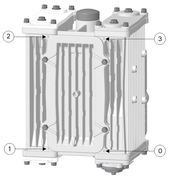
The following figure shows the slot identifier on the router chassis.

Figure 1. Module Slot Identifiers

0

Slot identifier 0 (CPU/Supervisor module slot)

2

Slot identifier 2 (UIM slot)

1

Slot identifier 1 (UIM slot)

3

Slot identifier 3 (UIM slot)

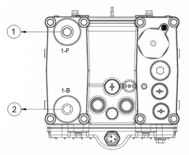
The following figure shows the antenna ports on slot 1.

Figure 2. Antenna Ports on Slot 1

1

Antenna Port 1-F

2

Antenna Port 1-B

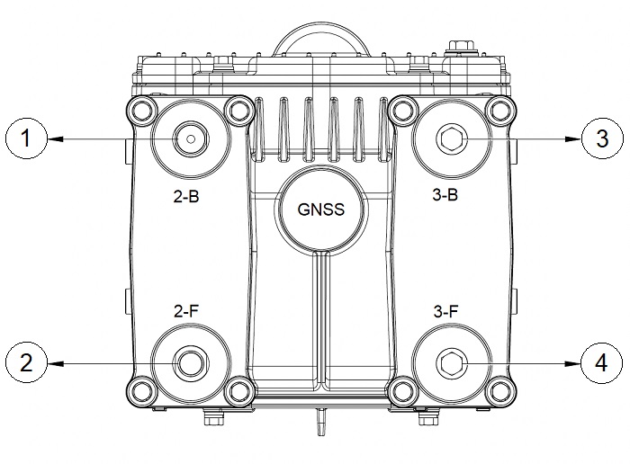
The following figure shows the antenna ports on slot s and slot 3.

Figure 3. Antenna Ports on Slot 2 and Slot 3

1

Antenna Port 2-B

3

Antenna Port 3-B

2

Antenna Port 2-F

4

Antenna Port 3-F

Recommended Module Installation Scenario and Antenna Selection

The following sections provide instructions on recommended module installation scenarios of WPAN and LTE modules, and guidance on antenna selection.

Single WPAN and Single LTE

For a deployment with one WPAN module and one LTE module, the following deployment scenarios are supported:

  • Anterix + WPAN—The IR8140 with a WPAN module and an IRMH-LTEA-EA-900 module supports Anterix Band 8c plus public LTE bands.

  • CBRS + WPAN—The IR8140 with a WPAN module and an IRMH-LTEA18-GL or IRMH-5GS6-GL module supports CBRS Band 48 plus public LTE bands.

Recommended installation and antenna selection:

  • Anterix + WPAN—Install WPAN module in slot 1 and IRMH-LTEA-EA-900 module in slot 3. Attach the ANT-5G-MP-OUT-N antennas directly to both modules.

  • CBRS + WPAN—Install WPAN module in slot 1 and IRMH-LTEA18-GL or IRMH-5GS6-GL module in slot 3. Attach ANT-5G-MP-OUT-N antenna directly on WPAN. Since there is no 900 MHz coexistence filter on these modules, use a 5 - 10 foot cable to provide RF isolation, to attach the ANT-5G-OMNI-OUT-N antenna on the LTE module.


Note


The antennas should maximize their relative vertical separation.


We recommend the following installation locations and antenna ports:

  • WPAN module—Slot 1, antenna port 1-F

  • LTE module—Slot 3, antenna port 3-F: Main LTE, antenna port 3-B: Div LTE


Note


For single WPAN deployment, we do not recommend the multi-element deployment, which may create an adverse position where the antennas are actually closer than intended.


Single WPAN and Dual LTE

For a deployment with one WPAN module and two LTE modules, choose IRMH-LTEA-EA-900 or IRMH-LTE-MNA-900 (with 900-MHz WPAN coexistence filter) as the LTE modules. Install the WPAN module in slot 1, and install the LTE modules in slot 2 and slot 3.

We recommend the following installation locations and antenna ports:

  • WPAN module—Slot 1, antenna port 1-F

  • LTE module 1—Slot 2, antenna port 2-F: Main LTE, antenna port 2-B: Div LTE


    Note


    For increased isolation and better WPAN and LTE performance, we recommend that you use ANT-5G-OMNI-OUT-N antennas with 10-ft cables for the LTE module in slot 2.


  • LTE module 2—Slot 3, antenna port 3-F: Main LTE, antenna port 3-B: Div LTE

Dual WPAN and Single LTE

For a deployment with two WPAN modules and one LTE module, choose IRMH-LTEA-EA-900 or IRMH-LTE-MNA-900 (with 900-MHz WPAN coexistence filter) as the LTE module.

We recommend the following installation locations and antenna ports:

  • WPAN module 1—Slot 1, antenna port 1-F

  • WPAN module 2—Slot 2, antenna port 2-F, using extension cable with ANT-5G-OMNI-OUT-N antenna

  • LTE module—Slot 3, antenna port 3-F: Main LTE, antenna port 3-B: Div LTE

Dual WPAN Only (no LTE Module)

For a deployment with two WPAN modules, we recommend that you install one WPAN module in slot 1 using antenna port 1-F. Install the second WPAN module in either slot 2 (using antenna port 2-F) or slot 3 (using antenna port 3-F), with 10-ft cables and ANT-5G-OMNI-OUT-N antennas.


Note


The antennas should maximize their relative vertical separation.


Installing a Module in the Router


Note


This is a general installation procedure for installing modules in the chassis of the router. For hardware installation and software configuration steps that are specific to your module, see the installation and configuration guide for the corresponding module.


To install a module in an available slot of the router:

Procedure

Step 1

Disable any installed battery backup units, and disconnect the router from AC power.

Step 2

If there is a blank or module in the applicable slot, follow the instructions provided in Removing a Module or a Blank from the Router.

Step 3

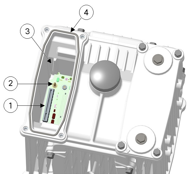
Ensure that gasket is fully contained in the groove and all the debris is removed from the gasket surface.

1

UIM interface connector

3

Chassis guide slot

2

Guide pin

4

Gasket

Step 4

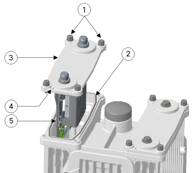
Align the module orientation indicator with the front of chassis. Align the carrier edge with the chassis guides and fully insert the module into the slot.

1

M6 bolts

2

Gasket

3

Module

4

Module orientation indicator

5

Align carrier edge with chassis guides

Step 5

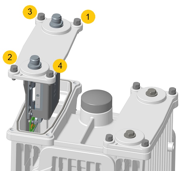
Use a 10-mm socket driver and tighten four bolts to 15 to 20 in-lbs in a sequence, as shown in the following figure. Then repeat torque sequence to 30 to 35 in-lbs for final torque.

Step 6

Attach the RF cables or antennas to the N-connectors on the UIMs if applicable.

Step 7

Connect the router to the AC power and to the network.

Step 8

Re-enable the Battery Backup Unit (BBU) using the command, as described in the Cisco Catalyst IR8140 Heavy Duty Series Router Software Configuration Guide.


Removing a Module or a Blank from the Router

To remove a module or a blank from the router:

Procedure

Step 1

Disable the installed battery backup units, and disconnect the router from AC power.

Step 2

Remove the cables attached to the UIM.

Step 3

Fully loosen the four M6 bolts on the UIM or the UIM blank using the 10-mm socket driver. (Do not remove bolts from the faceplate.)

1

M6 bolts

2

Gasket

3

Module orientation indicator

Step 4

Use your hands to gently pull the module or the blank from the router.

Step 5

Ensure that the gasket is fully contained in groove and all debris is removed from gasket surface.

Step 6

Do not leave the slot open and unattended. Install a new module or a blank, as described in Installing a Module in the Router.

Step 7

Connect the router to AC power and to the network.

Step 8

Re-enable the BBU using the commands, as described in the Cisco Catalyst IR8140 Heavy Duty Series Router Software Configuration Guide.