Connecting the Router

This chapter provides installation instructions for the Cisco Catalyst Industrial Router 8140 Heavy Duty Router. The procedures you must follow depend on your network environment and specific requirements.

These topics are discussed:

Before Installing

Read the safety warnings in this section and the Installation Safety and Site Preparation before beginning the installation procedures.

Preventing Electrostatic Discharge Damage

Many of these components are sensitive to electrostatic discharge (ESD) damage, which can occur when electronic cards or components are handled improperly, resulting in complete or intermittent failures.


Caution


To prevent ESD damage, follow these guidelines:

  • Always use an ESD wrist or ankle strap and ensure that it makes good skin contact.

  • Connect the equipment end of the strap to an unfinished chassis surface.

  • Place any removed memory card on an antistatic surface or in a static shielding bag. If the card is going to be returned to the factory, immediately place it in a static shielding bag.

  • Avoid contact between the card and clothing. The wrist strap protects the card from ESD voltages on the body only; ESD voltages on clothing can still cause damage.

  • Do not remove the wrist strap until the installation is complete.


Cabling Guidelines

Follow these guidelines for using cables with the router:

  • Position cables so that they do not place strain on the router connectors.

  • Organize cables into bundles when necessary to avoid intertwining.

  • Inspect cables to ensure adequate routing and bend radius.

  • Install cable ties that comply with your site requirements.

Connecting to AC Power

When connecting the router to AC power, you must ensure that the following conditions are met:

  • AC power can be readily and conveniently removed from the router. The power should not be removed by disconnecting the AC power connector on the unit. It should be removed by disabling AC power at the power circuit.


    Warning


    The plug-socket combination must be accessible at all times, because it serves as the main disconnecting device. Statement 1019


    Caution


    Before connecting or disconnecting the power cord, remove AC power from the power cord using a suitable service disconnect.


  • Protect AC power plugs and AC receptacles from water and other outdoor elements. You can use a UL-listed waterproofing enclosure that is suitable for covering the AC receptacle and AC power plug that supplies power to the unit, as described in Article 406 of the National Electric Code (NEC).

  • When you install the unit outdoors, or in a wet or damp location, the AC branch circuit that powers the unit should have ground fault protection (GFCI), as required by Article 210 of the NEC.

  • If the power cord goes through a metal cover, a bushing should be installed to prevent fraying of the cord. When using a strain relief bushing, you should follow these recommendations:

    • Use properly sized parts

    • Use bushings that are safety certified

    • Use parts that are suitable for outdoor installation

  • Ensure that the user-supplied AC power plug is certified for outdoor use and has a minimum IP67 rating.

The following sections describe the AC power cable and the procedure to connect to AC power.

AC Power Cable

The router supports the Cisco AC power cable that is shipped with the unit. One end of the cable has the router AC power connector, the other end is unfinished and you must attach an AC power plug, or terminate the cable at your installation site. The AC power plug or termination method you use depends on the power source, such as a junction box, at your site.

If you attach an AC power plug:

  • Use a plug that complies with local and national electrical codes.

  • Verify that the connection between the cable and plug is weatherproof.


Note


You might have to cut the cable if a specific cable length is needed for your installation.


Caution


Ensure that the power source is OFF before connecting or disconnecting the power cord wires from the power source.


Caution


To attach the appropriate connector to the AC power cable, follow the manual or other instructions provided by the electrical equipment vendor, ensuring that you comply with the electrical codes for your installation location.


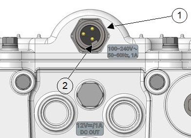
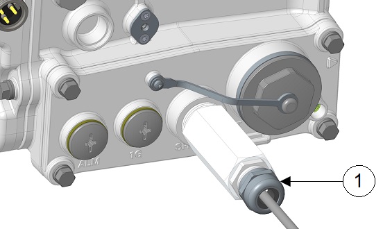
Figure 1. Router AC Power Cable (Router Connector End)

Connecting to AC Power

To connect the router's AC connector to an AC power source, perform this procedure. When connecting the router AC power connector, always connect the router end of the cable first. When removing the AC power connector, always disconnect the router end of the cable last.

Procedure


Step 1

Verify that the unit is grounded, as described in Grounding the Router.

Step 2

Turn off the power to the AC power source at the designated circuits.

Step 3

Align the notch in the AC power cable connector with the key in the router AC power connector, and then push the cable connector into the router connector. When the cable connector is fully seated, rotate the cable connector ring clockwise until it is tight.

Figure 2. Router AC Connector and AC Connector Key

1

AC power connector

2

AC connector key

Step 4

Confirm that the router antennas are connected to the router before you apply power to the router.

Step 5

Connect the other end of the AC power cable to the power source, using the instructions that came with the connecting device.

Step 6

Turn on the AC power at the designated circuits.

The router powers on and boots the software image.


Reset Button

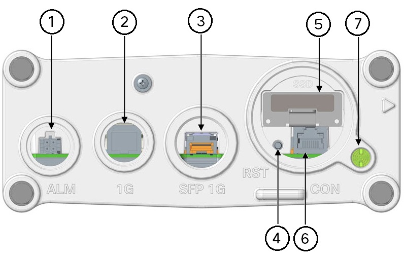
The following figure shows the reset button on the CPU module.

Figure 3. CPU Module Components

1

Alarm port with Micro-fit 4P connector with cable port seal.

2

10/100/1000 Mbps Ethernet port

3

SFP One Gigabit Ethernet

4

Reset button

5

SSD module

6

Console port (accessible when plug is removed)

7

SYS LED


Caution


When you use the Reset button to restore the router to the factory default software configuration, the current software configuration is permanently deleted from the router.


Do not use the Reset button to power the router on and off; the router powers on immediately after it is connected to an AC power source.

The Reset button must be pressed and held for at least 5 seconds to return the router to factory default. If the router is equipped with BBU, you must either disable BBU charge-discharge or enable BBU transportation mode prior to removing the AC power in order to fully power down the router. After that, simultaneously press the Reset button while applying power to the router.

Accessing the Reset Button

You must use a nonmetallic pin or any other thin metal tool that is no larger than 3/16 inches in diameter to access and press the Reset button.

Checking the System (SYS) LED

To verify that the router has been successfully installed, check the System (SYS) LED on the router base. When the router starts, the SYS LED displays any of these states.

Table 1. SYS LED States

State

Description

Off

System is not powered on.

Blinking green

System is in boot-up phase or in ROMMON.

Solid green

System is operating normally.

Solid yellow

System is receiving power, but there is an internal error. For example, interface is administratively unshut but is down because of cable disconnection.

Blinking amber

Registered interface is down.

Note

 
The registered interface must not be administratively shut down.

Additional Router Connections

This section provides information about making other, additional router cable connections. Follow the procedures in this section based on your network configuration and requirements.

External Connections and Chassis Cable Ports

When connecting the router's internal ports to external cables or exterior devices, you must thread the router cables through the chassis cable ports designated for this purpose. Some chassis ports are reserved for specific cables and the remaining ports can be used based on your network configuration and cabling requirements.


Caution


When you make router cable connections through the ports, you must use cable glands, as described in Using Cable Glands, to protect the router's interior from environmental elements, including moisture, heat, cold, and dust. Failure to use cable glands with the chassis cable ports can result in damage to the router.


Note


We recommend that you cover the ports mentioned in this section with a PG 13.5 plug when they are not in use. Ensure that you torque the PG 13.5 plug to 10-12 in-lbs.


Using Cable Glands

This section describes how to use cable glands with the router cables that are threaded through the chassis cable ports, as described in External Connections and Chassis Cable Ports.


Caution


The cable glands must be used for all the cables that are threaded through the router chassis cable ports to prevent exposing the router's interior to environmental elements.


Ordering Cisco Cable Glands

You can order a cable gland kit from Cisco using the model number IR-IP67GLAND. Each kit contains one cable gland.

Tools You Must Have

You must have these tools to connect cable glands:

  • #3 Phillips screwdriver to remove port seals from the router

  • Adjustable wrench that spans to 1 3/8" (for SFP Extender and M42 Plug)

  • 5/8" 6 Pt socket driver (for SFP Plug)

  • 15/16-inch (24-mm) open-end wrench

Cable Glands

Figure 4. Cable Glands, Assembled
Figure 5. Cable Gland Components

Item

Name

Description

1

Adapter

Connects directly to the chassis cable port on the router.

2

Grommet

Secures the split gasket over the cable.

3

Split gasket

Fits over the cable and creates a liquid-tight seal inside the glands.

4

Cap

Fits over the gasket-and-cable assembly and connects it to the chassis cable port.

Cable Requirements

Cables used with the cable glands should meet the following criteria:

  • Outdoor-rated

  • UV-stabilized

  • Diameter of 0.20-0.35 inches (5.08-8.89 mm)


Caution


Cables must be a minimum of 0.20 in. in diameter to create an adequate seal within the cable glands. Using smaller cables could result in an inadequate seal, and expose the router's interior to environmental elements.


Cable Glands Installation

Follow the steps provided in this section for every cable that you will connect through the chassis cable ports on the router. Step 4 and Step 5 can be done ahead of time and the prepared cable gland assembly can be transported to the router installation site.

The cable glands components referred to in this section are shown in Cable Gland Components.

The following figure shows an Ethernet cable, but the steps are the same for all cable types.

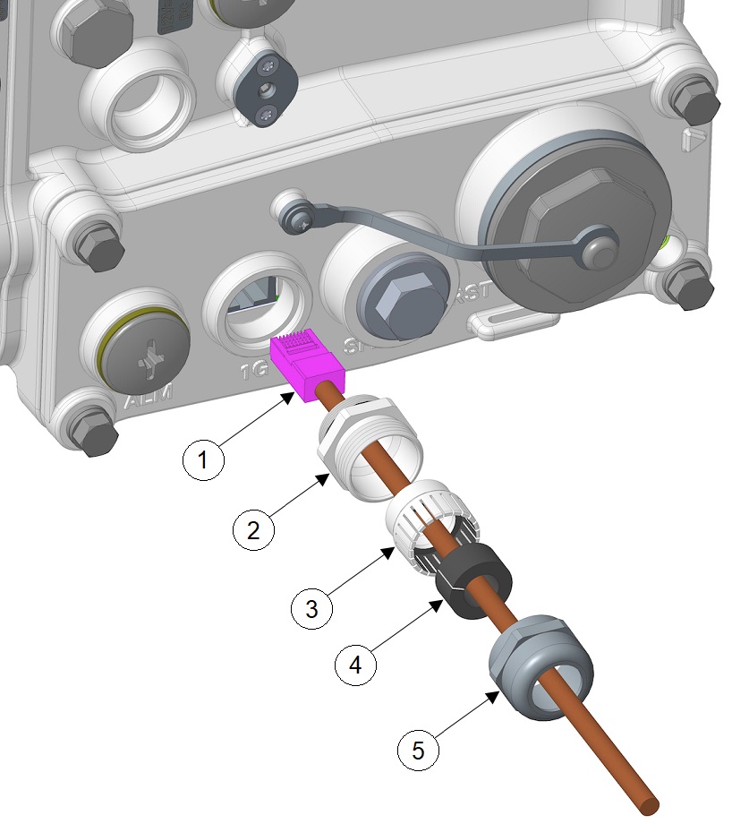
Figure 6. Cable Gland Components Threaded on a Cable

1

Cable connector (to router)

3

Split gasket

2

Grommet

4

Cap

Procedure

Step 1

Verify that the cable you are using meets the requirements described in Cable Requirements.

Step 2

Remove the port plug from the port on the router. Use the #3 Phillips screwdriver, if needed.

The router is shipped with port plugs in unused ports.

Step 3

Use your hands to attach the cable glands adapter (item 1 in Cable Gland Components) into the chassis cable port on the router.

Step 4

Thread the following cable gland components over the cable in this order (Cable Gland Components Threaded on a Cable):

  1. Cap

  2. Split gasket

  3. Grommet

Step 5

Slide the split gasket along the cable and into the grommet, pressing firmly to ensure that the gasket is completely seated in the grommet.

Step 6

Thread the connector-end of the cable through the router port and insert it into the corresponding router connector.

Step 7

Align and press the grommet-gasket assembly into the adapter.

Step 8

Slide the cap along the cable, over the grommet, and then onto the adapter.

Step 9

Hand-tighten the cap, and then use the open-end wrench to tighten it until the split gasket seals around the cable (6 to 7 foot-pounds of torque). There should be 5-10 pounds of cable-pull support.


Connecting the Console Port

See CPU Module Components for the console port location.

To configure the router through the Cisco IOS CLI, you must establish a connection between the router console port and either a terminal or a PC with a terminal emulation program, such as PuTTY or TeraTerm. The console port is located on the router's exterior and is labeled CON.

Use this port to connect a PC terminal, enabling you to log directly into the router's system software to perform a configuration or execute other commands.


Caution


The console port does not support cable glands. When a cable is connected to this port, the router's interior is exposed to environmental elements, which can damage the port and the router's interior. This port should be exposed only during terminal sessions, when a cable is connected to the port. This port should never be left unattended when in use. When not in use, cover the console port with an M42 plug that is attached to the CPU module. Ensure that you torque the M42 plug to 13 to 15 in-lbs.


Connecting

This section describes how to connect a PC terminal to the console port.

Your router kit includes a console cable with an RJ-45 connector on one end, and a DB-9 connector on the other end.

  • When a terminal is connected to the console port, you can connect directly to the router and configure it. You can connect a PC terminal to this port while the router is operating normally.

  • To connect a PC terminal to the router, you must provide one of the following adapters, depending on the device port—RJ-45-to-DB-25 female DTE adapter, RJ-45-to-DB-9 female DTE adapter (labeled TERMINAL), or USB-to-DB-9 adapter.

  • To remove the RJ-45 cable from the console port, compress the retention latch on the RJ-45 connector while removing the cable from the port. Use any small, flat, nonmetallic tool to press the latch while pulling the cable from the port.

To connect a PC or PC terminal to the console port:

Procedure


Step 1

Connect the RJ-45 connector on the console cable to the console port on the router.

Step 2

If your device requires a DB-9 adapter, connect the adapter you provide to the DB-9 connector on the cable.

Step 3

Connect the adapter-end or DB-9 connector-end of the console cable to your terminal or PC.

Note


A typical connection to a PC is through the PC's USB port. A DB-9 to USB adapter is required for that case if you use the included Cisco console cable. Alternately, you can use the RJ45-to-USB Cisco Router Console cables, that do not require an additional adapter.


Connecting the SFP Port

See CPU Module Components for the SFP port locations.

Small Form-Factor Pluggable (SFP) modules are transceiver devices that plug into the router's SFP port. The transceiver connects the electrical circuitry of the module with the optical network.

The SFP module used on each port must match the wavelength specifications at the other end of the cable. The cable must not exceed the stipulated cable length for reliable communications.

Use only Cisco SFP transceiver modules with the router. Each SFP transceiver module supports the Cisco Quality Identification (ID) feature that allows a Cisco switch or router to identify and validate that the transceiver module is certified and tested by Cisco.


Warning


Class 1 laser product. Statement 1008


Caution


Do not remove the dust plugs from the fiber-optic SFP module port, or the rubber caps from the fiber-optic cable until you are ready to connect the cable. The plugs and caps protect the SFP module ports and cables from contamination and ambient light.


Caution


We recommend that you not install or remove the SFP module while the fiber-optic cable is attached to it because of the potential damage to the cables, to the cable connector, or to the optical interfaces in the SFP module. Disconnect the cable before you remove or install an SFP module.


Materials and Tools You Must Have

You must have these tools and materials to install the SFP transceiver module:

Connecting a Fiber-Optic Cable to the Router

The Cisco Fiber Kit is required to support fiber-optic network connections.

Your require the following materials for connecting the fiber-optic cable to the router:

  • Small form-factor pluggable (SFP) transceiver module

  • SFP module adapter

  • Duplex LC fiber-optic cables. The outer diameter of the fiber optic cable should be 0.24 to 0.47 inches (6 to12 mm).

  • Adjustable wrench that adjusts to 1 1/8" minimum

You can connect the fiber-optic networking cable to the SFP port. The SFP transceiver module is used to connect the cable to the SFP port. To install the SFP transceiver module and the cable, follow this procedure:

Procedure


Step 1

Ensure that all the power sources have been disconnected from the router.

Step 2

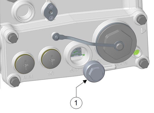
Remove the ¾ NPT covering plug (see 1 of the following figure) from the SFP port by following the guidelines given in this step.

The SFP port covering plug is designed to be removed only once, and then be replaced with the SFP adapter. The plug does not have a rubber O-ring, but is fixed in place using a thread seal tape on the threads during manufacturing. While removing the plug, you need to ensure that its hex bolt-head does not get stripped.

Use a 5/8” (16-mm) 6-point socket wrench to loosen the hex bolt-head SFP port plug. Firmly and carefully, turn the socket wrench counter-clockwise to loosen the plug. This requires a torque of 1–2 ft-lb (0.73–1.4 Nm).

Though not ideal, a 5/8” (16-mm) 12-point socket wrench can be used too. A crescent wrench is to be used only if the socket wrenches are not available. Do not use a pipe or monkey wrench for this task, because this will strip the hex bolt-head.

Step 3

Insert the SFP module into the SFP port, and ensure that it latches properly. See #__ for assembly detail.

Step 4

Loosen the cable gland’s nut (round end of the cable gland) by turning counterclockwise, but do not remove it.

Step 5

Feed the terminated fiber cable through the gland and adapter, as shown in the following figure.

Note


The optic fiber connectors are too big to pass through the cable gland. That is the reason why you need to thread the cable through the gland from the unterminated end (even if the cable is quite long).

Figure 7. Duplex LC Fiber Optic Cable

1

Duplex LC optic fiber connector

2

Optic fiber cable

Step 6

Insert the LC optic fiber connector-end of the cable into the SFP module adapter. Do not attach the cable gland to the adapter yet. See the following figure.

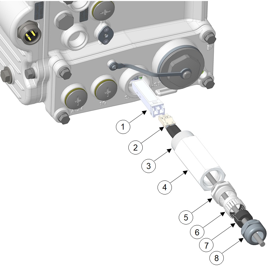
Figure 8. Exploded View of Connecting Fiber-Optic Cable to the Router

1

SFP module

5

Adapter base

2

SFP cable

6

Grommet

3

Extender threads

7

Gasket

4

Extender

8

Compression cap

Step 7

Insert the LC optic fiber connector into the SFP module and ensure that it latches into place.

Step 8

Apply sealing tape or sealant to the threads of the extender, and then thread the extender into the SFP port of the router chassis. Use an adjustable wrench to tighten the threaded end of the cable gland to 6 to 7 lb-ft (8.1 to 9.5 Nm).

Step 9

Thread the adapter base into the extender with 3 to 4 ft-lbs of torque.

Step 10

Insert keyed grommet into the adapter base, and insert the gasket into the grommet.

Step 11

Tighten the compression cap (1) until the grommet and gasket compress on to the cable and provides seal and cable stress relief. Use an adjustable or open-end wrench to tighten to 2.7 to 3.2 lb.ft (3.66 to 4.34 Nm).

Caution


When removing this SFP assembly, it is absolutely imperative that you proceed in the reverse order of this installation. Start by loosening the cable gland's nut.


Connecting the Ethernet Port

See CPU Module Components for the Ethernet port location.

The router features a Gigabit Ethernet port for connecting the router to an Ethernet network through a hub or switch.

  • One or two Ethernet cables are typically provided with the router. Additional cables and transceivers can be ordered from Cisco. For ordering information, contact customer service.

  • When connecting a cable to the Ethernet port, you must use a cable gland and thread the cable through the chassis cable port on the router. See External Connections and Chassis Cable Ports.


Warning


Do not work on the system or connect or disconnect cables during periods of lightning activity. Statement 1001


Connecting an Ethernet Cable to the Router

The following tools and materials are required:

  • Shielded outdoor-rated Ethernet (CAT5e or better) cable

  • RJ-45 connector and installation tool

  • #3 Phillips screwdriver

To connect the shielded Ethernet cable to the router, follow these steps:

Procedure


Step 1

Ensure that all the power sources to the router are turned off.

Step 2

Verify that the router is grounded, as described in Grounding Instructions.

Step 3

Remove the PG13.5 plug-and-seal ring (1) from the router chassis with the #3 Phillips screwdriver.

Step 4

Loosen the cable gland’s nut (round end of the cable gland) by turning it counter-clockwise, but do not remove.

Step 5

Insert the unterminated end of the Ethernet cable through the sealing nut end of the cable gland, and pull several inches of the cable through the adapter.

Step 6

Install an RJ-45 connector on the unterminated end of the Ethernet cable using your Ethernet cable installation tool.

Step 7

Carefully insert the RJ-45 cable connector into the Ethernet port opening on the router chassis, and connect to the internal Ethernet connector, as shown in the following figure.

1

RJ-45 cable connector

4

Split gasket

2

Adapter base

5

Compression cap

3

Grommet

Step 8

Thread the adapter base into the Ethernet port and tighten with 3 to 4 ft-lbs of torque.

Step 9

Insert keyed grommet into the adapter base.

Step 10

Install the split gasket around the cable, and then insert the gasket into the compression ring.

Step 11

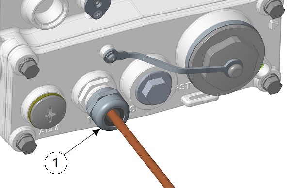
Tighten the compression cap (1 in the following figure) until the grommet and gasket compress on to the cable and provide seal and cable stress relief. Use an adjustable or open-end wrench to tighten to 2.7 to 3.2 lb.ft (3.66 to 4.34 Nm).

Step 12

Route your Ethernet cable.


Connecting the Alarm Port

See CPU Module Components for the alarm port location.

Attach the alarm port to an alarm system to monitor software events and errors. The alarm port supports two bidirectional channels that can be configured as inputs or outputs independently.

The alarm-trigger setting determines when an alarm is sent to the attached alarm system.

  • You can connect this port while the router is operating normally.

  • If you use an alarm system on your network, connect the alarm port to an alarm system, using an alarm cable that you provide.

  • When connecting this port to an external alarm system, you must use cable glands and thread cables through the chassis cable ports on the router. See External Connections and Chassis Cable Ports.

  • When configuring the alarm channel as an input, the alarm input will detect an open or closed external circuit, such as a relay.

  • When configuring the alarm as an output, the alarm output requires users to provide their own external relay and external pull-up resistor in the range of 3 to 60 V. The resistor value needs to be strong enough to energize the relay, but weak enough to stay under 100 mA when the pullup is forced to 0 V.

The procedure to connect to the alarm port is identical to the one described in Connecting an Ethernet Cable to the Router, with the exception that the connector is not RJ45, but a 4-pin Micro-Fit. See Alarm Port for details.