Cisco NCS 1000 Breakout Patch Panel and Modules Overview

This chapter provides an overview for Cisco NCS 1000 Breakout Patch Panel and Cisco NCS 1000 Breakout Modules.


Note


In this chapter, "breakout panel" refers to the "Cisco NCS 1000 Breakout Patch Panel". "breakout modules" refer to the "Cisco NCS 1000 Breakout Modules".

Cisco NCS 1000 Breakout Patch Panel

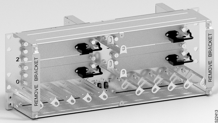
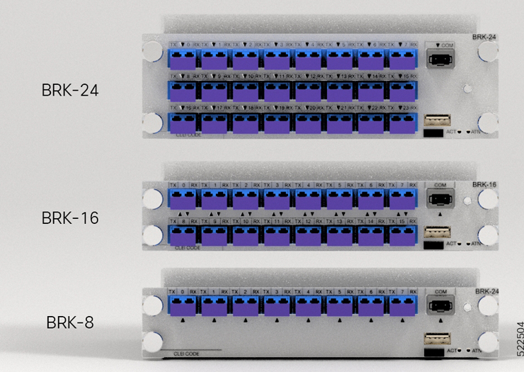
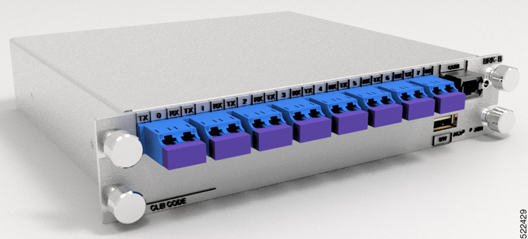
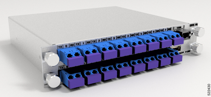
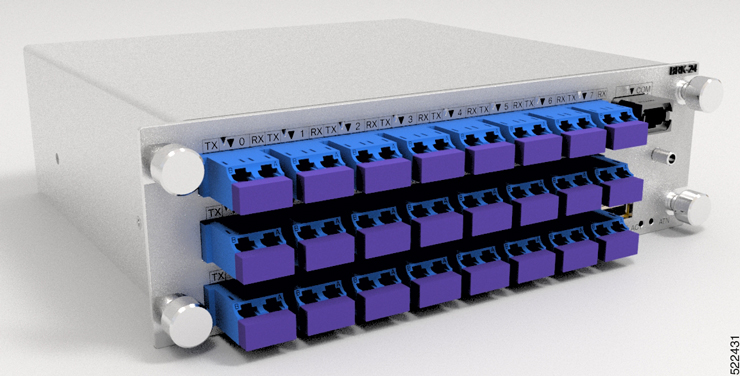
Cisco NCS 1000 Breakout Patch Panel is colorless breakout-modular patch panel. It is powered by the NCS 1010 chassis using a single USB 2.0 cable from the NCS 1010 EITU. The breakout panel contains four USB 2.0 connections that power the breakout modules. It allows connections between the OLT-C and OLT-R-C line cards that are installed in the NCS 1010 chassis and the four breakout modules using MPO cables. The breakout panel supports up to 72 colorless mux/demux channels and 8-directional interconnections. The breakout panel is 4 RU high and has adjustable fiber guides for fiber routing. The empty slots are covered with dummy covers. The panel is shipped with USB 2.0 connectors that are connected to the corresponding dummy covers. The plastic transparent cover can be installed in front of the panel for fiber protection. The panel is designed to fit a 19-inch rack. The panel can also be installed on ETSI and 23-inch rack using adapter brackets.

Figure 1. NCS1K-BRK-SA
NCS1K-BRK-SA

Cisco NCS 1000 Breakout Modules

The breakout modules are a set of three optical breakout units. The modules can be connected to the A/D 4–11, A/D 12–19, A/D 20–27 and A/D 28–33 MPO connector ports of the OLT-C and OLT-R-C line cards to provide ROADM node internal connections and for local channels add/drop.

A USB 2.0 connection from the NCS 1010 chassis powers up the breakout panels. The modules monitor signals, check connection verification, and retrieve the inventory data.

The modules have two operational modes:

  • Low-power mode—Retrieves only inventory data.

  • High-power mode—Full monitoring and checks features are available.

The three breakout modules can be used in C-band.

Breakout Modules Faceplate

Figure 2. Breakout Modules Faceplate
Breakout Modules Faceplate

The breakout panel supports the following breakout modules:

  • NCS1K-BRK-8

    Figure 3. 8-port Breakout Module
    8-port Breakout Module

    The NCS1K-BRK-8 module provides the breakout of 16 fibers from an MPO-24 connector to 8 duplex line card connectors. It essentially performs an optical connection adaptation of MPO-to-LC connectors for the ADD/DROP signals of the MPO ports of OLT line cards. For each port (MPO and LC), power monitors with tone detection capability are available. A filtered optical loopback (191.175 THz) from one MPO input port (fiber-1) to all MPO output ports is available for connection verification.

  • NCS1K-BRK-16

    Figure 4. 16-port Breakout Module
    16-port Breakout Module

    The NCS1K-BRK-16 module provides the breakout of 16 fibers from an MPO-24 connector to 16 duplex LC connectors. The signals on each fiber from the MPO input ports are split over two LC output ports by a 1x2 optical splitter. The signals from the two adjacent input LC ports are combined into a single MPO output port through a 1x2 optical coupler. For each port (MPO and LC), power monitors with tone detection capability are available. A filtered optical loopback (191.175 THz) from one MPO input port (fiber-1) to all MPO output ports is available for connection verification.

  • NCS1K-BRK-24

    Figure 5. 24-port Breakout Module
    24-port Breakout Module

    The NCS1K-BRK-24 module provides the breakout of 16 fibers from an MPO-24 connector to 24 duplex LC connectors. The signals on each fiber from the MPO input ports are split over three LC output ports by a 1x3 optical splitter. The signals from the three adjacent input LC ports are combined into a single MPO fiber output port through a 1x3 optical coupler. For each port (MPO and LC), power monitors with tone detection capability are available. A filtered optical loopback (191.175 THz) from one MPO input port (fiber-1) to all MPO output ports is available for connection verification.

For more information on the port details of the breakout modules, see Cisco NCS 1010 datasheet.

Breakout Modules Port Label Descriptions

NCS1K-BRK-8 Port Label Description

NCS1K-BRK-8 is equipped with 1x MPO-24 connector (with only 16 fibers connected) and with 8x LC-duplex connectors.

Table 1. NCS1K-BRK-8 Port Label Description

Port

Connector Type

Connector Label

Operating Frequency Range [THz, (nm)]

Note

COM-TX/RXi, (i=1–8)

MPO/MPT

COM

197.2–185.9 (1520–1612)

DIR-i-TX/RX (i=1–8)

LC

TX-i-RX

197.2–191.275 (1520–1567.34)

191.0-185.9 (1569.6–1612)

Signals from 191.275 to 191 THz are filtered out from/to the DIR-i-TX/RX ports.

NCS1K-BRK-16 Port Label Description

NCS1K-BRK-16 is equipped with 1x MPO-24 connector (with only 16 fibers connected) and with 16x LC-duplex connectors.

Table 2. NCS1K-BRK-16 Port Label Description

Port

Connector Type

Connector Label

Operating Frequency Range [THz, (nm)]

Note

COM-TX/RXi, (i=1–8)

MPO/MPT

COM

197.2–185.9 (1520–1612)

CH-i-TX/RX (i=1–16)

LC

TX-i-RX

197.2–191.275 (1520–1567.34)

191.0–185.9 (1569.6–1612)

Signals from 191.275 to 191 THz are filtered out from/to the CH-i-TX/RX ports.

NCS1K-BRK-24 Port Label Description

NCS1K-BRK-24 is equipped with 1x MPO-24 connector (with only 16 fibers connected) and with 24x LC-duplex connectors.

Table 3. NCS1K-BRK-24 Port Label Description

Port

Connector Type

Connector Label

Operating Frequency Range [THz, (nm)]

Note

COM-TX/RXi, (i=1–8)

MPO/MPT

COM

197.2–185.9 (1520–1612)

CH-i-TX/RX (i=1–24)

LC

TX-i-RX

197.2–191.275 (1520–1567.34)

191.0–185.9 (1569.6–1612)

Signals from 191.275 to 191 THz are filtered out from/to the CH-i-TX/RX ports.

Breakout Module LEDs

Table 4. Feature History

Feature Name

Release Information

Feature Description

Port Status for Breakout Modules

Cisco IOS XR Release 7.9.1

The LEDs for optical ports (COM, TX-i-RX) in the breakout modules will now indicate port status in these colors:

  • Red—Presence of major and critical alarms that could be traffic-impacting

  • Amber—Presence of minor alarm when tone generation or tone detection is initiated. Tone detection uses a specific probe signal to verify the connection between OLT line cards and the breakout modules.

  • Green—Normal operations with no system alarms.

The breakout module LEDs indicate the system status and the status of the optical ports.

Three color LEDs (green, amber, and red) are present near each optical port (COM, DIR-i, and CH-i) to indicate the port status. The optical ports vary depending on the breakout module.

Table 5. Status of the Optical Port LEDs

Port LED

Color

Status

COM, DIR-i, or CH-i

Red

Indicates major and critical alarms such as RX-LOS-P, which could be traffic-impacting. These alarms are raised when there is a loss of signal (LOS) or when the OTS power reading is below the Fail-Low threshold.

Amber

Indicates minor alarms that are raised when initiating tone generation and tone detection for connection verification.

Green

Indicates that the patch panel is operational and has no alarm.

ACT

Green

Indicates the active status for the USB connection.

ATN

Green

Indicates the attention condition for the USB connection.