Cisco NCS 1010 Overview
Cisco NCS 1010 is a next-generation optical line system optimized for ZR/ZR+ WDM router interfaces. Its salient features are:
-
Provides point-to-point connectivity between routers with WDM interfaces.
-
Multiplexes the signals received from multiple routers over a single fiber.
-
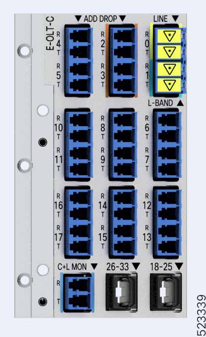
With one MPO port, it can be scaled to 8 Degree but if needed node can be scaled to higher than 8 degree, using more EXP MPO ports.
-
Caters to C-band WDM transmission to maximize capacity, and can be enhanced to C+L combined band in the future.
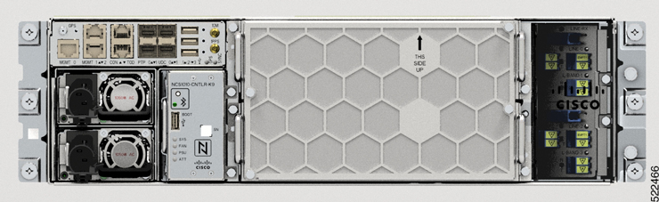
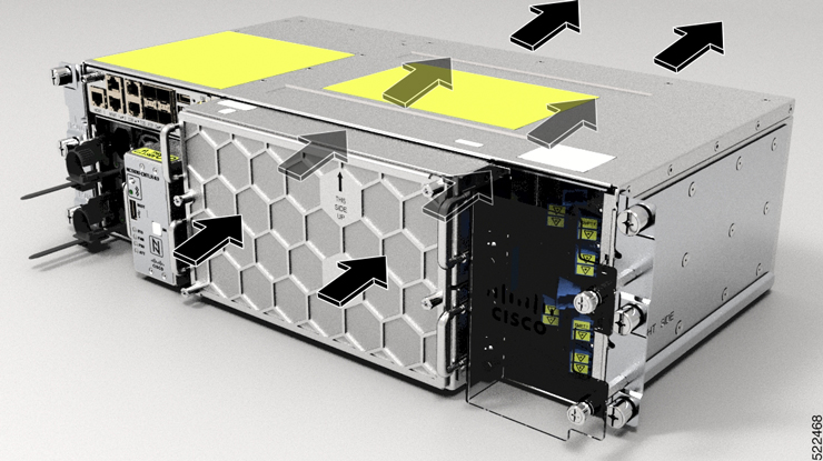
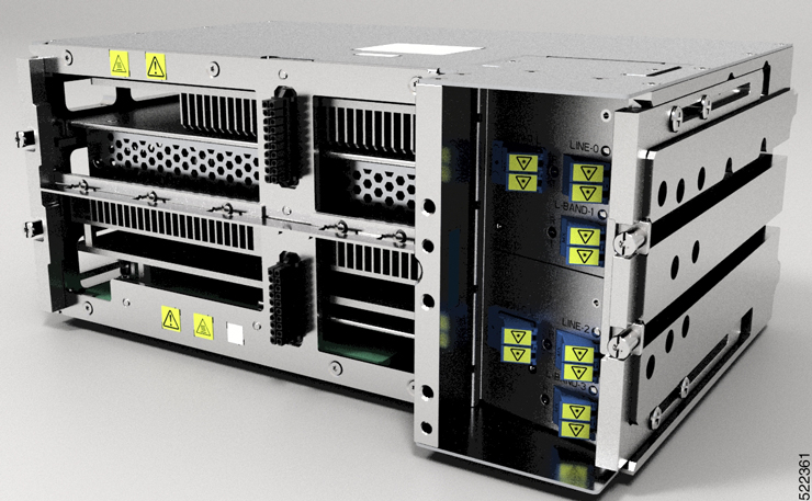
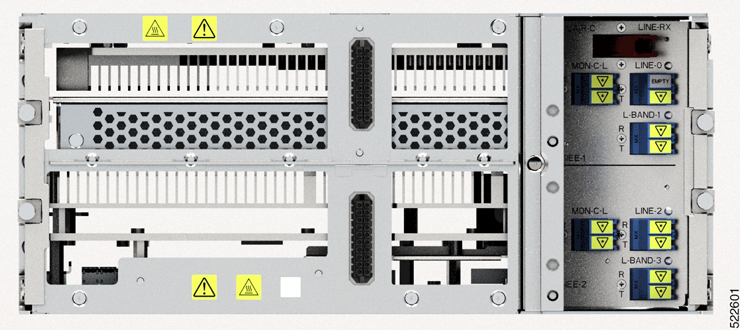
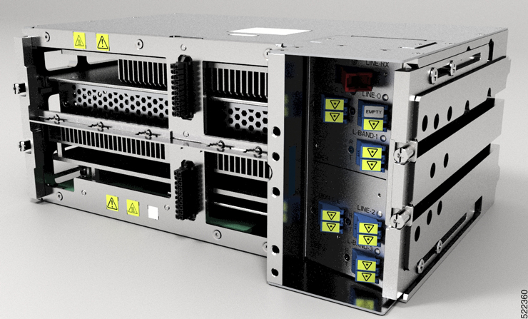
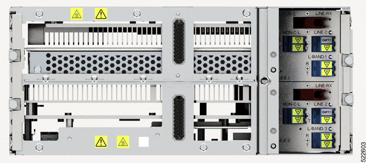
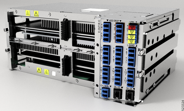
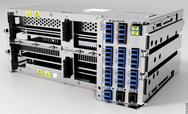
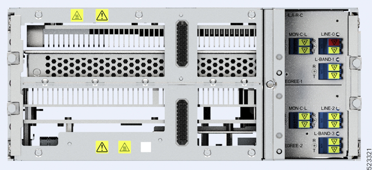
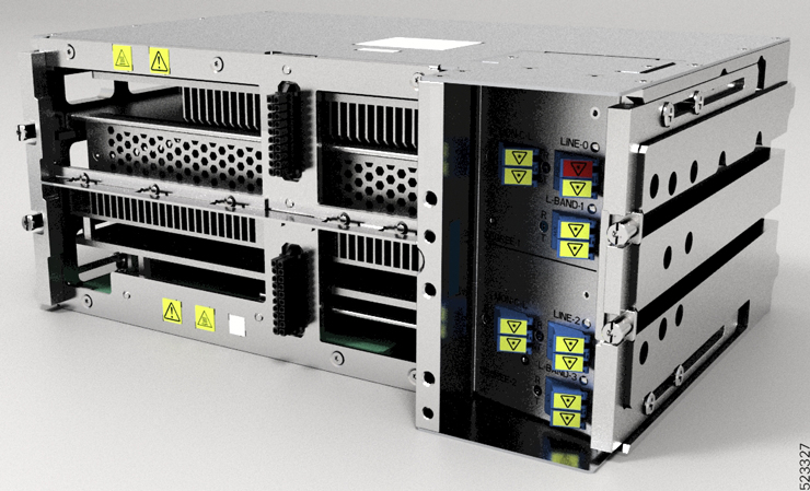
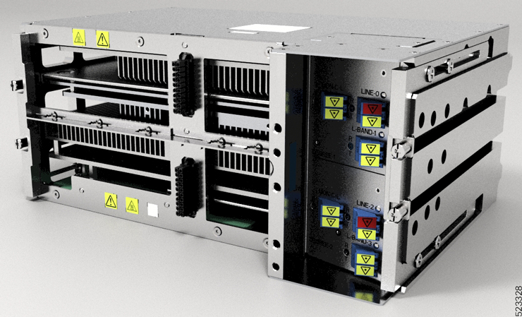
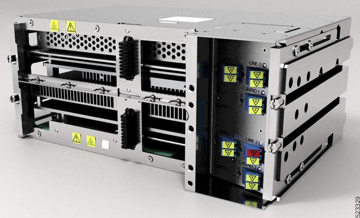
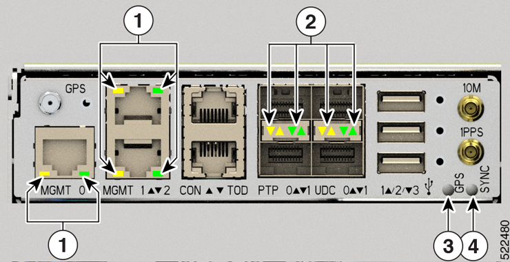
Cisco NCS 1010 is a 3RU chassis that has an in-built External Interface Timing Unit (EITU) and the following field-replaceable modules.
-
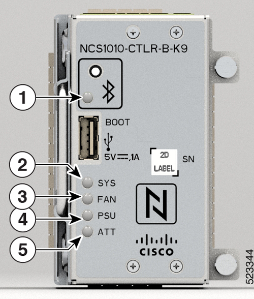
Controller
-
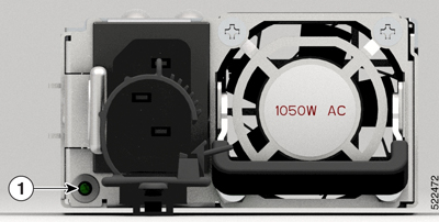
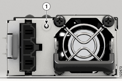
Two power supply units
-
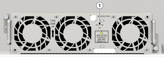
Two fan trays
-
Fan filter
-
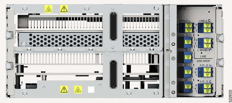
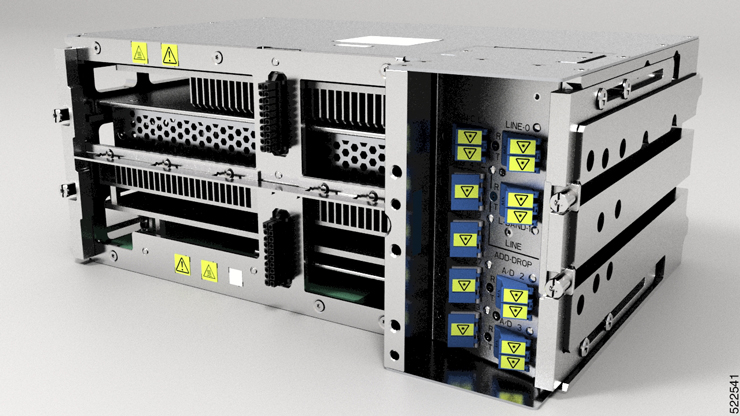
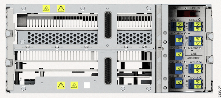
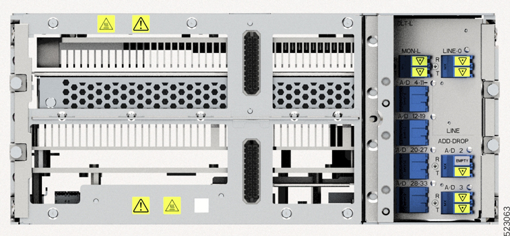
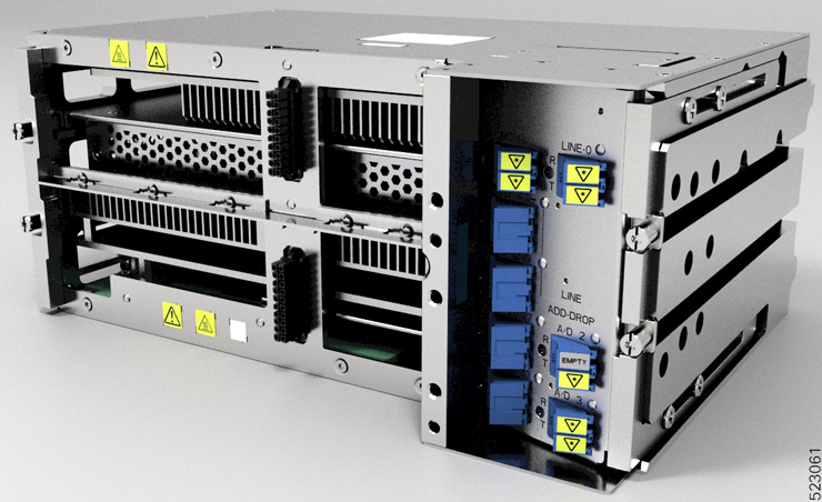
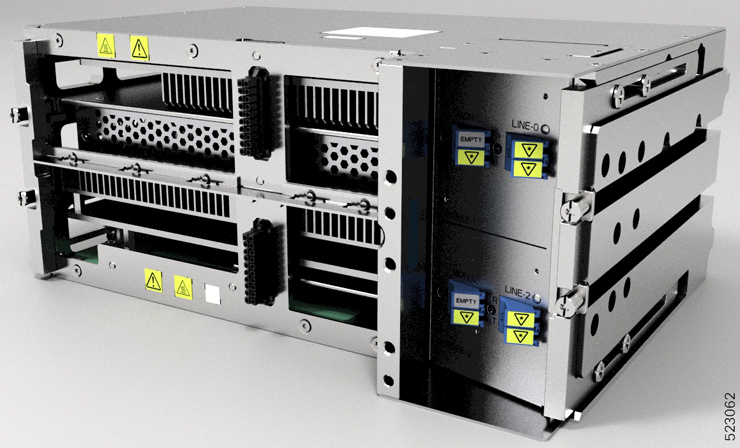
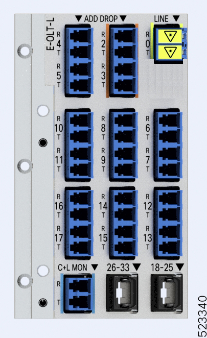
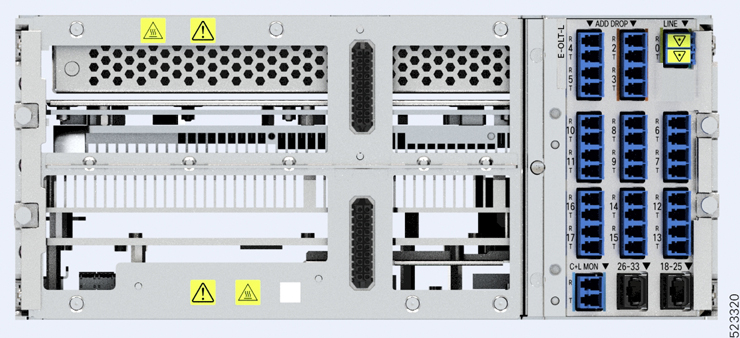
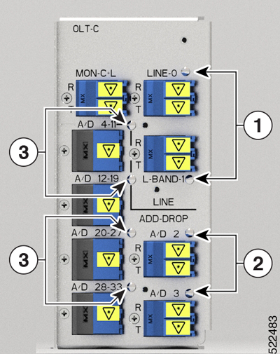
Line card
The Cisco NCS 1010 chassis supports the following line cards.
Table 2. Supported Line Cards Line Card
Description
Release
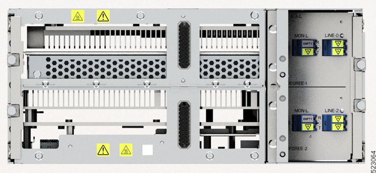
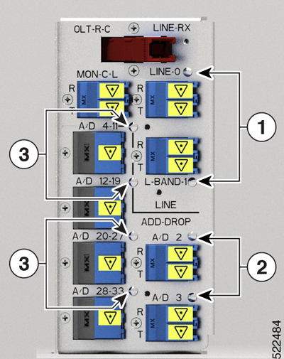
C-band Optical Line Terminal without Raman
Cisco IOS XR Release 7.7.1
C-band Optical Line Terminal with Raman
Cisco IOS XR Release 7.7.1
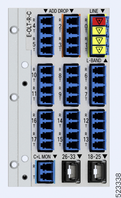
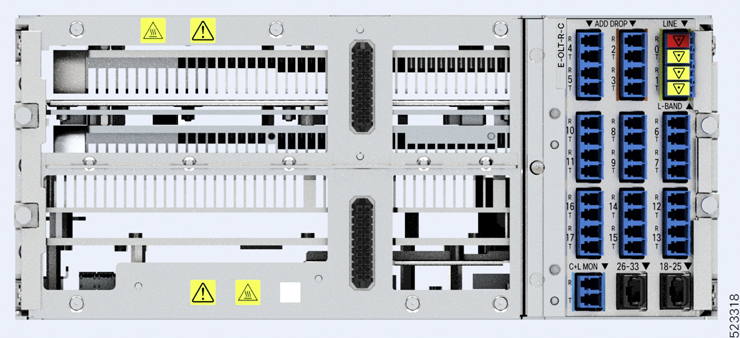
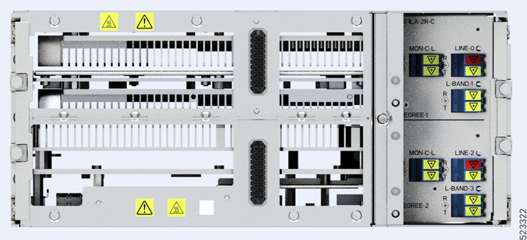
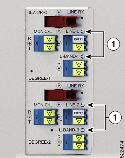
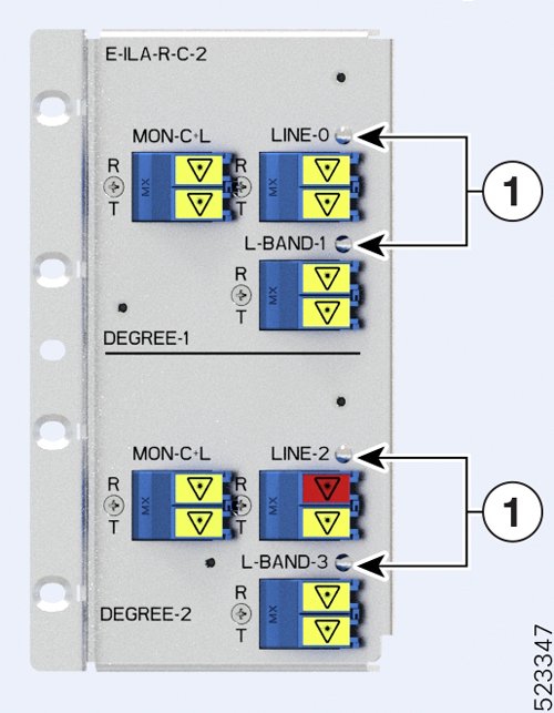
C-band In-Line Amplifier without Raman
Cisco IOS XR Release 7.7.1
C-band In-Line Amplifier with one side Raman
Cisco IOS XR Release 7.7.1
C-band In-Line Amplifier with both sides Raman
Cisco IOS XR Release 7.7.1
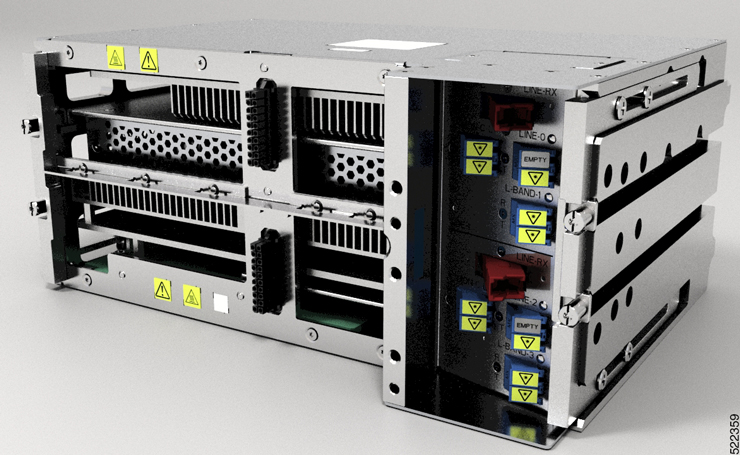
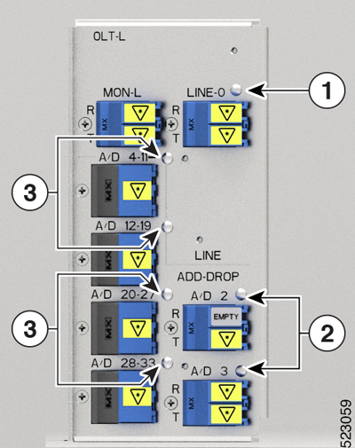
L-band Optical Line Terminal without Raman
Cisco IOS XR Release 7.9.1
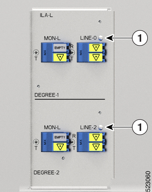
L-band In-Line Amplifier without Raman
Cisco IOS XR Release 7.9.1
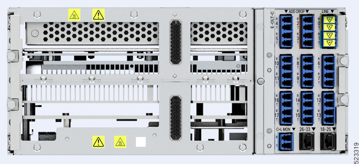
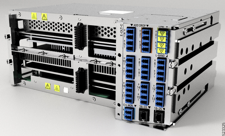
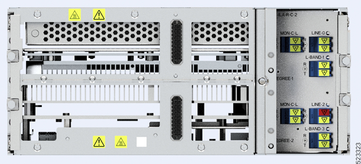
C-band Optical Line Terminal without Raman, Enhanced
Cisco IOS XR Release 7.10.1
C-band Optical Line Terminal with Raman, Enhanced
Cisco IOS XR Release 7.10.1
L-band Optical Line Terminal without Raman, Enhanced
Cisco IOS XR Release 7.10.1
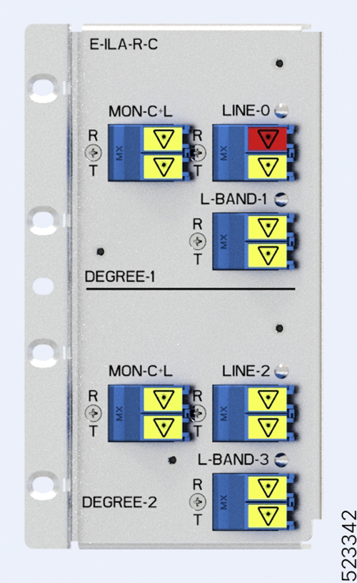
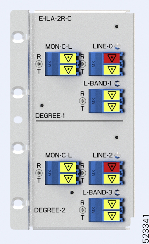
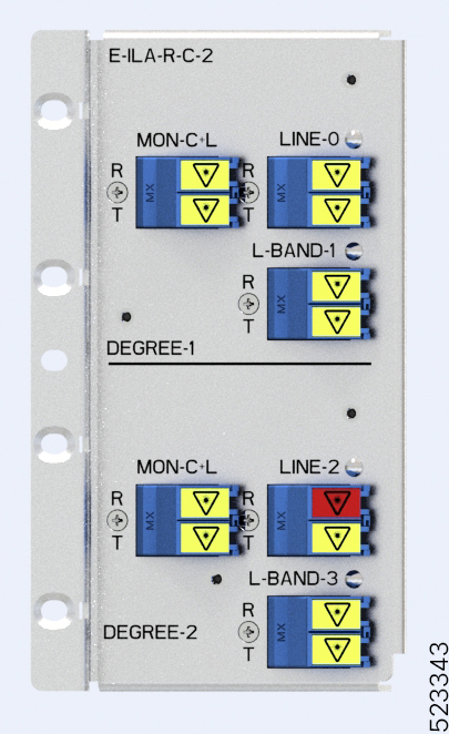
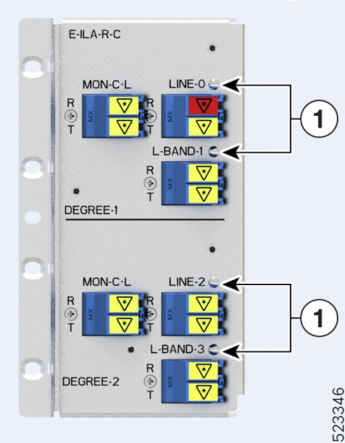
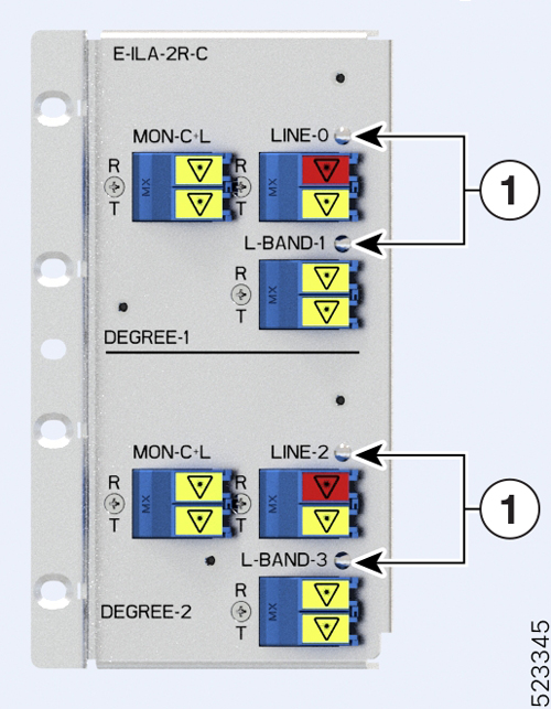
C-band In-Line Amplifier with East-facing Raman, Enhanced
Cisco IOS XR Release 7.10.1
C-band In-Line Amplifier with both sides Raman, Enhanced
Cisco IOS XR Release 7.10.1
C-band In Line Amplifier with West-facing Raman, Enhanced
Cisco IOS XR Release 7.11.1
For more information about the Cisco NCS 1010 chassis, see Cisco NCS 1010 Data Sheet.
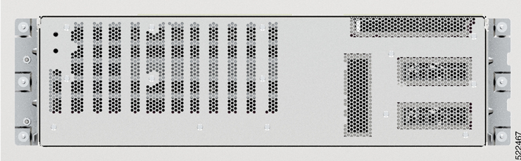
The airflow on Cisco NCS 1010 is front to back. Cool air enters the chassis through the fan trays and exhausts through the rear end of the chassis.


 Feedback