Install Cisco NCS 1000 Breakout Patch Panel and Modules

This chapter contains tasks to install Cisco NCS 1000 Breakout Patch Panel and Cisco NCS 1000 Breakout Modules.


Note


In this chapter, "breakout panel" refers to the "Cisco NCS 1000 Breakout Patch Panel". "breakout modules" refer to the "Cisco NCS 1000 Breakout Modules".

Rack Compatibility

The Cisco NCS 1000 Breakout Patch Panel can be installed in a standard ANSI/EIA (19"), ANSI (23"), or ETSI (21") rack.

  • The rack can be two-post type or four-post type rack.

  • The 19" and 23" racks must be compliant with "EIA Universal" holes.

  • The ETSI Rack must be compliant with "ETSI Universal" holes.
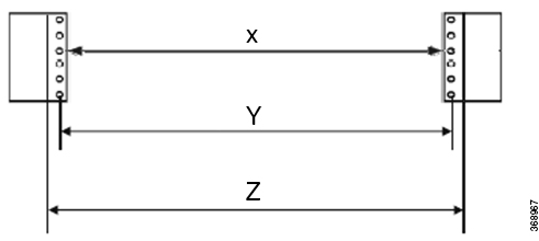
Figure 1. Rack Specification

Rack Type

Rack Front Opening X

Rack Mounting Hole Center-Center Y

Mounting Flange Dimension Z

ANSI 19" racks

450.8mm (17.75")

465mm (18.312")

482.6mm (19")

ANSI 23" racks

552.45mm (21.75")

566.7mm (22.312")

584.2mm (23")

ETSI 21" racks

500.0mm(19.68")

515.0mm(20.276")

533.4mm(21")

Ground Description

The unpainted surface between the adapter bracket, optical modules, and patch panels, ensure proper grounding of the breakout patch panels. The adapter bracket, the straight adapter brackets, and the Z-shaped adapter brackets are unpainted and treated with conductive finishing.

Ground Connection Warnings

Take note of the following ground connection warnings:


Warning


Statement 1024—Ground Conductor

This equipment must be grounded. To reduce the risk of electric shock, never defeat the ground conductor or operate the equipment in the absence of a suitably installed ground conductor. Contact the appropriate electrical inspection authority or an electrician if you are uncertain that suitable grounding is available.


Warning


Statement 1101—Connected To Grounded Outlet

In the Scandinavian countries (Denmark, Finland, Iceland, Norway, and Sweden) the appliance must be connected to a grounded outlet.


Ground the Breakout Panel


Caution


When terminating the frame ground, do not use soldering lug connectors, screwless (push-in) connectors, quick connect connectors, or other friction-fit connectors.


This task describes the steps to ground the breakout panel.

Procedure


Step 1

Verify that the office ground cable is connected to the top of the rack and the office ground, according to local site practice.

Step 2

Remove any paint and other nonconductive coatings from the surfaces between the breakout panel ground and bay frame ground point. Clean the mating surfaces and apply appropriate antioxidant compound to the bare conductors.

Step 3

Identify the ground stamp on the breakout panel to attach the ground lug.

Step 4

Crimp a #6 AWG ground cable to the dual-hole ground lug.

Step 5

Align the dual-hole ground lug to the breakout panel.

The ground points are present on the front and rear side of the breakout panel, as shown in the following figure.

Figure 2. Front Side Grounding Option
Front Side Grounding Option
Figure 3. Rear Side Grounding Option
Rear Side Grounding Option

1

Double-hole Ground Lug

2

Lock Washers

3

M5 Pan Head Phillips Screws

Step 6

Tighten the M5 pan head screw to torque value of 3.1 N-m (27.4 lbs-in).

Step 7

Terminate the other end of the ground cable either at the office ground point or the rack ground point.


Rack Mount Warnings

Take note of the following rack-mount safety warnings.


Warning


Statement 1006—Chassis Warning for Rack-Mounting and Servicing

To prevent bodily injury when mounting or servicing this unit in a rack, you must take special precautions to ensure that the system remains stable. The following guidelines are provided to ensure your safety:

  • This unit should be mounted at the bottom of the rack if it is the only unit in the rack.

  • When mounting this unit in a partially filled rack, load the rack from the bottom to the top with the heaviest component at the bottom of the rack.

  • If the rack is provided with stabilizing devices, install the stabilizers before mounting or servicing the unit in the rack.


Warning


Statement 1032—Lifting the Chassis

To prevent personal injury or damage to the chassis, never attempt to lift or tilt the chassis using the handles on modules, such as power supplies, fans, or cards. These types of handles are not designed to support the weight of the unit.


Warning


Statement 1098—Lifting Requirement

Two people are required to lift the heavy parts of the product. To prevent injury, keep your back straight and lift with your legs, not your back.


Install Breakout Panel Adapter Brackets

This task explains how to install the adapter brackets to the ANSI or ETSI standard equipment rack.


Note


The breakout panel does not need adapter brackets to fit into an ANSI 19-inch rack.


Before you begin

Ensure you completed the following tasks:

Procedure


Step 1

To mount the adapter brackets to the standard equipment rack, perform one of the following actions:

  • For a 23 inch (584.2 mm) ANSI configuration, perform the following steps.

    Note


    Use the "NCS1K-23-KIT" accessory kit for installing the breakout panel on the 23-inch rack. For more information, see Package Contents.

    1. Align the screw holes of the left bracket against the screw holes of the left rack.

    2. Place the screws to hold the left bracket on the left rack.

    3. Align the screw holes of the right bracket against the screw holes of the right rack.

      Figure 4. Installing the Adapter Brackets on the 23-inch Rack
      Installing the Adapter Brackets on the 23-inch Rack

      1

      Left and Right Adapter Brackets

      2

      12-24 Pan Head Screws

    4. Place the screws to hold the right bracket on the right rack.

  • For an ETSI configuration, align the screw holes of the Z-shaped adapter brackets against the rack screw holes.

    Note


    Use the "NCS1K-ETSI-KIT" accessory kit for installing the breakout panel on the ETSI rack. For more information, see Package Contents.

    Figure 5. Installing the Adapter Brackets on an ETSI Rack
    Installing the Adapter Brackets on an ETSI Rack

    1

    Adapter Bracket

    2

    M6 x 20mm Length Screws

Step 2

Using a screwdriver, tighten the screws to a torque value of 4.65 N-m (41 lbs-in).


What to do next

Install the NCS 1000 Breakout Patch Panel

This task explains how to install the breakout panel into the ETSI and 23-rack adapter brackets.

Before you begin

Procedure


Step 1

Hold the bottom side of the breakout panel and align the breakout panel to the rack.

Warning

 
Using the top or bottom covers to lift the breakout panel may damage the equipment.
Figure 6. Installing the Breakout Panel on a 19-inch Rack
Installing the Breakout Panel on a 19-inch Rack

1

12–24 x 0.5" Length Pan Head Screws

Figure 7. Installing Breakout Panel on an ETSI Rack
Installing Breakout Panel on an ETSI Rack

1

NCS1K-BRK-SA

2

12–24 x 0.5" Length Pan Head Screws

Figure 8. Installing Breakout Panel on a 23-inch Rack
Installing Breakout Panel on a 23-inch Rack

1

NCS1K-BRK-SA

2

12–24 x 0.5" Length Pan Head Screws

Step 2

Tighten the 12–24 pan-head screws to a torque value of 4.65 N-m (41 lbs-in).


What to do next

Install the NCS 1000 Breakout Modules

This task explains how to install the following breakout modules into the breakout panel.

  • NCS1K-BRK-8

  • NCS1K-BRK-16

  • NCS1K-BRK-24

Before you begin

Procedure


Step 1

Loosen the captive screws to remove the front brackets in the breakout panel.

Figure 9. Removing Front Brackets from Breakout Panel
Removing Front Brackets from Breakout Panel

1

Front Brackets

Step 2

Establish grounding for the breakout panel. For more information, see Ground the Breakout Panel.

Step 3

Remove the USB 2.0 connection from the USB dummy cover.

Figure 10. Removing USB 2.0 Connection
Removing USB 2.0 Connection

1

USB 2.0 Cable

2

Ground Lug

Step 4

Loosen the captive screws to remove the dummy cover from the breakout panel. For installing the 24-port breakout module, you need to also remove the smaller dummy cover above the USB dummy cover. See Removing Dummy Cover for 24-Port Module.

Note


A line marking is provided on the faceplate of the breakout panel where 8/16-port breakout modules can be installed.

Figure 11. Removing USB Dummy Cover for 8/16-Port Module
Removing USB Dummy Cover for 8/16-Port Module

1

USB Dummy Cover

Figure 12. Removing Dummy Cover for 24-Port Module
Removing Dummy Cover for 24-Port Module

1

USB Dummy Cover

2

Dummy Cover

Step 5

Insert the breakout module into the empty slot.

Figure 13. Inserting 8-Port Breakout Module into the Breakout Panel
Inserting 8-Port Breakout Module into the Breakout Panel

1

8-Port Breakout Module (NCS1K-BRK-8)

2

Captive Screws

Figure 14. Inserting 16-Port Breakout Module into the Breakout Panel
Inserting 16-Port Breakout Module into the Breakout Panel

1

16-Port Breakout Module (NCS1K-BRK-16)

1

Captive screws

Figure 15. Inserting 24-Port Breakout Module into the Breakout Panel
Inserting 24-Port Breakout Module into the Breakout Panel

1

24-Port Breakout Module (NCS1K-BRK-24)

1

Captive Screws

Step 6

Tighten the captive screws of the breakout module to a torque value of 0.65 N-m (5.75 lbs-in).

Step 7

Connect the associated USB 2.0 connecter to the breakout module.

Figure 16. Connecting USB 2.0 Connector for 8-Port Breakout Module
Connecting USB 2.0 Connector for 8-Port Breakout Module

1

USB 2.0 Connector

Figure 17. Connecting USB 2.0 Connector for 24-Port Breakout Module
Connecting USB 2.0 Connector for 24-Port Breakout Module

1

USB 2.0 Connector

Step 8

Repeat steps Step 3 through Step 7 to install the rest of the breakout modules.

The following image displays the complete installation of the breakout modules into the breakout panels.

Figure 18. Breakout Panel with Breakout Modules Installed
Breakout Panel with Breakout Modules Installed

Breakout Panel Cable Management

The breakout panel accommodates high-density cable connections from the breakout modules. The LC, MPO, and USB cables exit the breakout panel through the right-, left-, or both sides. The USB 2.0 cable connection must exit from the lower left side of the breakout panel and connect to the USB 0 port of the NCS 1010 EITU. The MPO cables must exit on the right side of the breakout panel to the MPO ports of the NCS 1010 OLT-C and OLT-R-C line cards. The LC cables can exit through the left-, right-, or both sides of the breakout panel. The following image shows the different orientations of the fibre guides:
Figure 19. Fiber Guides
Fiber guides tilted in opposite directions.

To exit the cables on both sides of the breakout panel, perform the following steps:

  • Tilt the bottom fiber guides inwards toward the USB 0 port on the faceplate.

  • Fix the protrusions of the fiber guides on the faceplate guide holes.

  • Tighten the captive screws.

  • Route the cables on both sides out of the breakout panel.

To exit the cables on the right side of the breakout panel, perform the following steps:

  • Tilt the bottom fiber guides to the left side facing downwards.

  • Tilt the top fiber guide to the right side facing upwards and tilt the middle fiber guide in the opposite direction.

  • Fix the protrusions of the fiber guides on the faceplate guide holes.

  • Tighten the captive screws.

  • Route the cables to the right side of the breakout panel.

To exit the cables on the left side of the breakout panel, perform the following steps:

  • Tilt the bottom fiber guides to the right side facing downwards.

  • Tilt the top fiber guide to the left side facing upwards and tilt the middle fiber guide to the opposite direction.

  • Fix the protrusions of the fiber guides on the faceplate guide holes.

  • Tighten the captive screws.

  • Route the cables to the right side of the breakout panel.

Figure 20. Routing of MPO and LC Cables
The LC cables route on both sides and MPO cables route on right side of the breakout panel.
1 LC Cable
2 MPO Cable
Figure 21. Routing of MPO and USB 3.0 Cables
The USB 2.0 cable routes to the left side and MPO cables route to the right side of the breakout panel to the NCS 1010.

Install and Route Fiber-Optic Cables


Warning


Statement 1051—Laser Radiation

Invisible laser radiation may be emitted from disconnected fibers or connectors. Do not stare into beams or view directly with optical instruments.


Note


Always clean all fiber connectors thoroughly before making the connection with the mating adapter. Very small particles can permanently damage the end of the mating fiber inside the breakout module, which makes regular cleaning imperative. For cleaning instructions, see Fiber-Optic Connector Cleaning and Maintenance.

Note


The breakout modules feature LC/MPO bulkhead adapters. Always use fiber-optic cables equipped with the corresponding (LC/MPO) connector type. Using any other type of connector results in damage to the connector or adapter, or both.

This procedure explains how to install and route fiber-optic cables from the OLT-C or OLT-R-C line card to the breakout module.

Procedure


Step 1

For an MPO cable installation, do the following:

  1. Remove the dust cap from the MPO adapter on the breakout module.

  2. Place the MPO cable connector in front of the corresponding COM port of the breakout modules.

  3. Align the keyed ridge of the MPO cable connector with the slot in the receiving adapter.

    Figure 22. Aligning MPO Fiber Cable Connector
    Aligning MPO Fiber Cable Connector

    1

    MPO Fiber Cable

    • 15454-24MPO-MPO-2

    • 15454-24MPO-MPO-4

    • 15454-24MPO-MPO-6

    • 15454-24MPO-MPO-8

  4. Gently push the cable connector into the adapter until you hear a click, which indicates that the latching system is engaged.

  5. Route the cables through the right side to the MPO ports A/D 4–11, A/D 12–19, A/D 20–27 and A/D 28–33 in the OLT-C or OLT-R-C line cards in the NCS 1010 shelf. See Breakout Panel Cable Management.

  6. Place the other end of the MPO cable connector in front of the corresponding ADD/DROP port of the line cards.

  7. Align the keyed ridge of the MPO cable connector with the slot in the receiving adapter.

  8. Gently push the cable connector into the adapter until you hear a click, which indicates that the latching system is engaged.

Step 2

For an LC cable installation, do the following:

  1. Remove the dust cap from the LC adapter on the breakout modules.

  2. Place the LC cable connector in front of the corresponding LC bulkhead adapter of the breakout modules.

  3. Align the keyed ridge of the cable connector with the slot in the receiving adapter.

    Figure 23. Aligning LC Cable Connector
    Aligning LC Cable Connector

    1

    LC Cable

  4. Gently push the cable connector into the adapter until you hear a click, which indicates that the latching system is engaged.

  5. Route the cables through the left or right side of the breakout panel. See Breakout Panel Cable Management.

  6. Place the other end of the LC cable connector in front of the corresponding unit.

  7. Align the keyed ridge of the LC cable connector with the slot in the receiving adapter.

  8. Gently push the cable connector into the adapter until you hear a click, which indicates that the latching system is engaged.


Install and Route the USB Cable

This task explains how to install and route the USB 3.0 cable into the NCS 1010 chassis.

Procedure


Step 1

Remove the dust cap from USB 0 port in the breakout panel.

Caution

 
Do not remove the dust cap from the PWR port. The PWR port will be supported in a future release. Avoid connecting the USB cable to the PWR port.

Step 2

Align the USB 3.0 cable connector to the inventory USB Type A receptacle (USB 0 port) present on the breakout panel.

Figure 24. USB 3.0 Cable Connection
USB 3.0 Cable Connection

1

USB 3.0

  • NCS1010-USB-3M=

  • NCS1010-USB-1M=

2

USB 3.0 Cable Screw

Step 3

Gently push the USB 3.0 cable connector in the USB Type A receptacle (USB 0 port) on the breakout panel.

Step 4

Tighten the captive screw to a torque value of 0.15 N-m (1.32 lbs-in) to secure the USB 3.0 cable in the receptacle.

Step 5

Route the other side of the USB 3.0 cable through the left side of the breakout panel.

Step 6

Connect the other side of the USB 3.0 cable to the USB 0 port on the NCS 1010 EITU.


Install Breakout Panel Plastic Cover

This task describes the steps to install the transparent plastic cover on the breakout panel.

Procedure


Step 1

Install the plastic cover to the breakout panel using six captive screws.

Figure 25. Installing the Plastic Cover on Breakout Panel
Installing the Plastic Cover on Breakout Panel

1

Plastic Cover

2

Captive Screws

Step 2

Using a screwdriver, tighten the captive screws to a torque value of 0.65 N-m (5.6 lbs-in).


Fiber-Optic Connector Cleaning and Maintenance

Connector cleaning is required to maintain the performance of fiber-optic circuits. It is important that both the LC/UPC connector at the end of the fiber-optic cable and the mating bulkhead adapter on the front panel of the patch panel and the optical modules are clean before the connection is made.


Warning


Statement 1051—Laser Radiation

Invisible laser radiation may be emitted from disconnected fibers or connectors. Do not stare into beams or view directly with optical instruments.


The following warning applies to disposal of chemicals and other materials used to clean connectors and adapters:


Warning


Statement 9001—Product Disposal

Ultimate disposal of this product should be handled according to all national laws and regulations.


Before installing the fiber-optic cable, always perform the cleaning procedure for cable connectors described in the following section. Whenever possible, inspect each connector before connecting it to the mating bulkhead adapter on the front panel.

The LC/MPO bulkhead adapters on the optical modules are less likely to get dirty if they are capped when not in use. Because the procedure for a thorough cleaning of these adapters is complicated, we recommend that you use a commercially available cleaning kit and closely follow the instructions included with the kit.

Customer Supplied Cleaning Materials

The Type A fiber optic connector cleaners, for example, CLETOP reel are recommended to clean the cable connectors, but are not supplied with the patch panel/optical modules.

When cleaning a paired cable connector (bulkhead mating adapter), always clean the mating adapter first.

If properly maintained (only used with clean, defect-free fiber connectors and capped when not in use), the mating adapter would not require cleaning. However, if you suspect the adapter is dirty, clean it by using the CLETOP stick swab.


Note


For multi-fiber cable assemblies, use specific cleaning tools or materials designed for the assembly type.

Clean the Bulkhead Mating Adapters

This task describes the steps to clean the bulkhead mating adapters.

Procedure


Step 1

Read the manufacturer (cleaning cartridge) instructions to insert the cartridge cleaning tip into the mating adapter.

Step 2

Slide the lever on the cartridge to swipe the mating surface.

Note

 
Always keep unused adapter ports and fiber connectors capped with a clean dust cap.

Clean Fiber-Optic Cable Connectors

This task describes the steps to clean the fiber-optic cables connectors.

The tools required to clean fiber connectors are:

  • Inspection microscope

  • Type A fiber-optic connector cleaner (CLETOP reel)

  • Optical swab

  • Optical receiver cleaning stick

Procedure


Step 1

Using an inspection microscope, inspect each fiber connector for dirt, cracks, or scratches.

Step 2

Replace any damaged fiber connectors.

Note

 
Replace all dust caps whenever the equipment is unused for 30 minutes or more.

Note

 
Do not reuse optical swabs. Keep unused swabs away from work surfaces.

Step 3

Clean the fiber connectors with CLETOP reel:

  1. Remove the dust cap from the fiber connector.

  2. Press the lever down to open the shutter door. Each time you press the lever, you expose a clean wiping surface.

  3. Insert the connector into the CLETOP cleaning cassette slot, rotate one-quarter turn, and gently swipe downwards.

  4. Use an inspection microscope to inspect each fiber connector for dirt, cracks, or scratches. If the connector is not clean, repeat the above substeps.

  5. Insert the fiber connector into the applicable adapter or attach a dust cap to the fiber connector.

    Note

     
    If you must replace a dust cap on a connector, first verify that the dust cap is clean. To clean the dust cap, wipe the outside of the cap using a dry lint-free wipe and the inside it using a CLETOP stick swab (14100400).