Stateful Switchover Between Redundancy Paired Intra or Inter-box Devices

Overview

Stateful switchover provides protection for network edge devices with dual Route Processors (RPs) that represent a single point of failure in the network design, and where an outage might result in loss of service for customers.

In specific Cisco networking devices that support dual RPs, stateful switchover takes advantage of Route Processor redundancy to increase network availability. When two route processors (RPs) are installed, one RP acts as the active RP, and the other acts as a backup, or standby RP. Following an initial synchronization between the two processors if the active RP fails, or is manually taken down for maintenance or removed, the standby RP detects the failure and initiates a switchover. During a switchover, the standby RP assumes control of the router, connects with the network interfaces, and activates the local network management interface and system console. Stateful switchover dynamically maintains Route Processor state information between them.

The following conditions and restrictions apply to the current implementation of SSO:

  • Calls that are handled by nondefault session application (TCL/VXML) will not be checkpointed prebridge.

  • Flow-through calls whose state has not been accurately checkpointed will be cleared with media inactivity-based clean up. This condition could occur if active failure happens when:

    • Some check point data has not yet been sent to the standby.

    • The call leg was in the middle of a transaction.

    • Flow around calls whose state has not been accurately checkpointed (due to either of the reasons mentioned above) can be cleared with the clear call voice causecode command.

For more information about the Stateful Switchover feature and for detailed procedures for enabling this feature, see the "Configuring Stateful Switchover" chapter of the Cisco IOS High Availability Configuration Guide, Release 12.2SR.

Feature Information

Table 1. Feature Information

Feature Name

Releases

Feature Information

Stateful Switchover Between Redundancy Paired Intra or Inter-box Devices

Baseline Functionality

Provides protection for network edge devices with dual Route Processors (RPs) that represent a single point of failure in the network design, and where an outage might result in loss of service for customers.

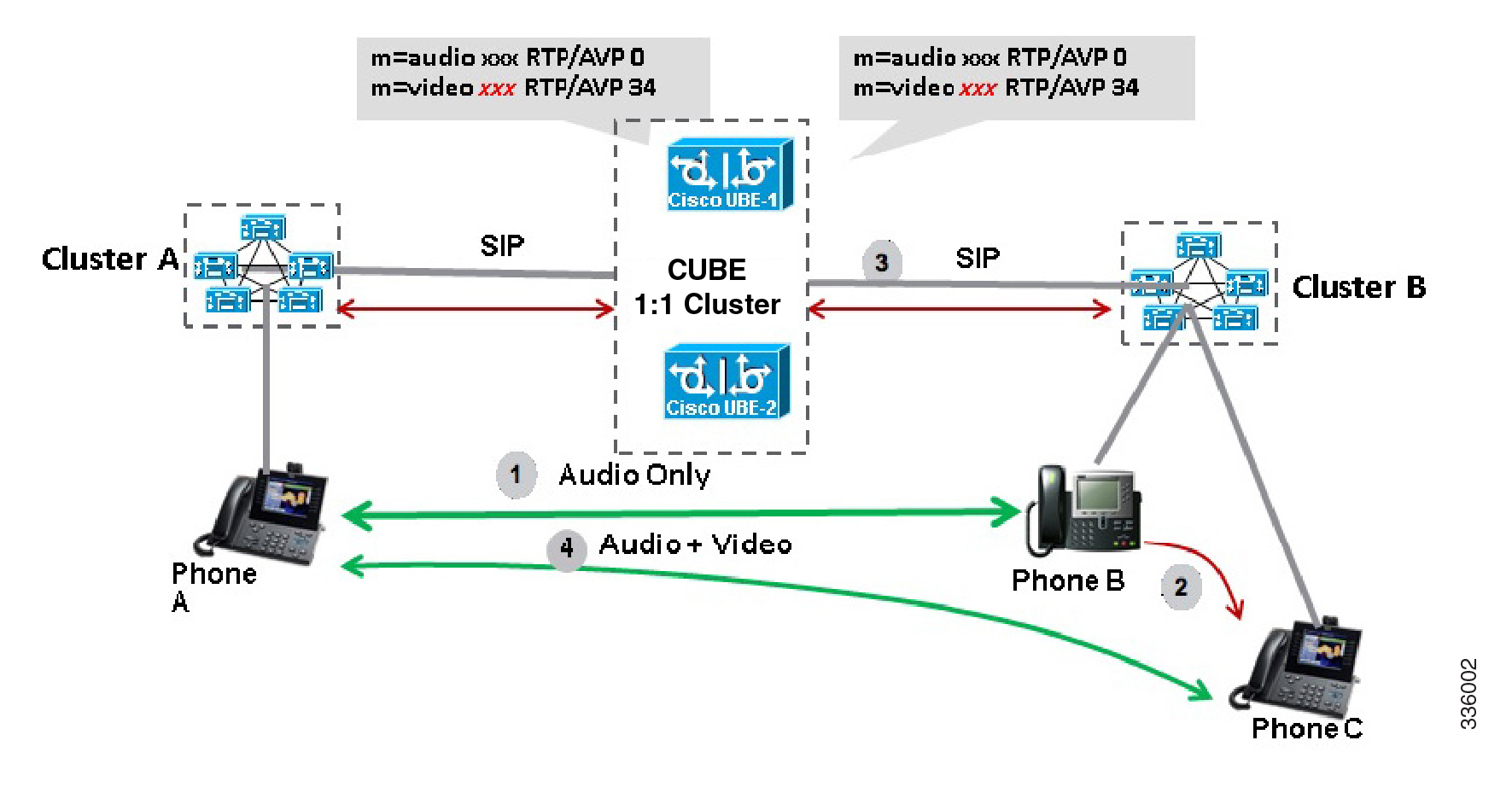
Call Escalation with Stateful Switchover

The call escalation workflow is as follows:

  1. The call starts as an audio call between Phone A (video-capable) and Phone B (only audio-capable) registered to two different Cisco Unified Communications Manager (CUCM) clusters connected using Cisco Unified Border Element (CUBE).

  2. The call is then transferred to Phone C, which is a video-capable phone.

  3. The media parameters within the reinvite are renegotiated end-to-end.

  4. The call is escalated to a video call.


Note


If the CUBE switchover happens at any instance, then audio calls will be preserved before escalation and video calls will be preserved after escalation.


Figure 1. Call Escalation

Call De-escalation with Stateful Switchover

The call de-escalation workflow is as follows:

  1. The call starts as a video call between Phone A and Phone B registered to two different Cisco Unified Communications Manager (CUCM) clusters connected using Cisco Unified Border Element (CUBE).

  2. The call is then transferred to Phone C, which is an audio-only phone.

  3. The media parameters within the reinvite are renegotiated end-to-end.

  4. The call is de-escalated to an audio-only call.


Note


If the CUBE switchover happens at any instance, then video calls will be preserved before de-escalation and audio calls will be preserved after de-escalation.


Figure 2. Call De-escalation

Media Forking with High Availability

Media forking with high availability is supported on ISR G2, ISR G3 and ASR platforms. When a primary call is connected and a forked call-leg is established on an active CUBE device, both the primary and the forked call-leg will be checkpointed in the standby CUBE device. If the active device goes down, the standby device ensures that the forking call is active and is able to exchange further transactions with the recording server with preserved calls such as hold/resume, transfer, conference, and so on. A recording server is a Session Initiation Protocol (SIP) user agent that archives media for extended durations, providing search and retrieval of the archived media. The recording server is a storage place of the recorded session metadata.

The active and standby devices must have the same configurations for checkpointing to happen correctly. The recorder can be configured both ways with a media profile and directly on a media class. The media profile can be associated under media class, and the media class can be applied to the incoming or outgoing dial-peer to start recording.

For more information, see the “Network-based Recording Using CUBE” module in the CUBE Protocol-Independent Features and Setup Configuration Guide.

Prerequisites for Stateful Switchover Between Redundancy Paired Intra- or Inter-box Devices

Cisco Unified Border Element (Enterprise)

  • Cisco IOS XE Release 3.2 or a later release must be installed and running on your Cisco ASR 1000 Series Router.

Cisco Unified Border Element

  • Cisco IOS Release 15.2(3)T or a later release must be installed and running on your Cisco Unified Border Element.

Restrictions for Stateful Switchover Between Redundancy Paired Intra- or Inter-box Devices

  • Call escalation and de-escalation are not supported in REFER consumption mode.

  • Session Description Protocol (SDP) passthru calls are not supported.

  • Resource Reservation Protocol (RSVP) is not supported.

  • Alternative Network Address Types (ANAT) for IPv4 or IPv6 interworking is not supported.

  • SDP passthrough calls are not supported for media forking.

  • Media flow-around fork calls are not checkpointed.

  • For high availability PROTECTED mode, redundancy group (RG) is not supported on cross-over cable. However, if cross-over cable is used and the connection flaps or if the RG link is connected using a switch and the switch resets, or if there is a switchover, then both the devices will go into PROTECTED mode resulting in no VoIP functionality.

High Availability Protected Mode and Box-to-Box Redundancy for ASR

To configure box-to-box high availability (HA) support for ASRs, use the mode rpr command (rpr is route processor redundancy) in redundancy configuration mode.


Note


  • Use the same hardware for both the ASR boxes in the active or standby pair to ensure compatibility before and after failover.

  • A separate physical interface must be used for checkpointing calls between the active and standby devices.


Self-reload in a voice HA-enabled device helps to recover the box-to-box HA pair from out-of-sync conditions. Instead of self-reload, you can configure the device to transition into protected mode. In protected mode:

  • Bulk sync request, call checkpointing, and incoming call processing are disabled.

  • The device in protected mode needs to be manually reloaded to come out of this state.

  • In a high availability scenario, if CUBE in standby redundancy group (RG) state is already in VoIP HA protected mode and a switchover occurs, causing the standby CUBE to become active on RG level, VoIP functionality is disabled. This is because incoming call processing is disabled in VoIP HA protected mode, so even when the standby CUBE assumes the active role on RG level, call processing remains impaired. The only way to restore call processing is to manually reboot the affected CUBE instance to exit protected mode.

To enabled the protected mode, use the no redundancy-reload command under “voice service voip” configuration mode. The default is redundancy-reload , which reloads control when the redundancy group (RG) fails.

Example: Configuring the Interfaces for ASR Devices

ASR (RG Infra-based)


interface GigabitEthernet0/0/0
 ip address 10.13.25.190 255.255.0.0
 negotiation auto
 redundancy rii 1
redundancy group 1 ip 10.13.25.123 exclusive

Support for Box-to-Box High Availability with Virtual IP Addresses

The OPTIONS ping with CUBE high availability feature adds the ability to match the incoming dial-peer in the context of the OPTIONS message, allowing response with the virtual IP address shared between the active and standby CUBEs. Box-to-box high availability is supported using virtual IP addresses for the signaling and media, by enhancing the CUBE response to an inbound OPTIONS ping message. This is possible because dial-peer matching of a request URI that does not have a user part is supported.


Important


When OPTIONS Ping SIP Trunk (from CUCM) is configured to CUBE that is running in HA mode, the SIP Trunk goes down whenever the active interface goes down. The SIP Trunk comes back in service, when the OPTIONS Ping next retry happens to CUBE HA node. The default retry time is 60 seconds.


Note


For configuration examples, see the Examples section about configuring interfaces (ISR and ASR) and configuring SIP binding.


Monitor Call Escalation and De-escalation with Stateful Switchover

Perform this task to monitor calls before and after escalation or de-escalation and before and after stateful switchover on active and standby CUBE devices. The show commands can be entered in any order.

SUMMARY STEPS

  1. enable
  2. show call active voice compact
  3. show call active video compact
  4. show call active voice stats
  5. show call active video stats

DETAILED STEPS


Step 1

enable

Enables privileged EXEC mode.

Example:

Device> enable
          

Step 2

show call active voice compact

Displays a compact version of call information for the voice calls in progress.

Example:

Device# show call active voice compact

<callID>  A/O FAX T<sec> Codec       type        Peer Address       IP R<ip>:<udp>
Total call-legs: 2
       512 ANS     T1     g711ulaw    VOIP        Psipp       9.45.38.39:6016
       513 ORG     T1     g711ulaw    VOIP        P123    10.104.46.222:6000

Step 3

show call active video compact

Displays a compact version of call information for the video calls in progress.

Example:

Device# show call active video compact

<callID>  A/O FAX T<sec> Codec       type        Peer Address       IP R<ip>:<udp>
Total call-legs: 2
       512 ANS     T19    H263        VOIP-VIDEO  Psipp       9.45.38.39:1699
       513 ORG     T19    H263        VOIP-VIDEO  P123    10.104.46.222:1697

Step 4

show call active voice stats

Displays information about digital signal processing (DSP) voice quality metrics.

Example:

Device# show call active voice stats

dur 00:00:16 tx:2238/85044 rx:1618/61484 dscp:0 media:0 audio tos:0xB8 video tos:0x0 
IP 9.45.25.33:58300 SRTP: off rtt:0ms pl:0/0ms lost:0/0/0 delay:0/0/0ms g711ulaw TextRelay: off Transcoded: No
dur 00:00:16 tx:1618/61484 rx:2238/85044 dscp:0 media:0 audio tos:0xB8 video tos:0x0
IP 9.45.25.33:58400 SRTP: off rtt:0ms pl:0/0ms lost:0/0/0 delay:0/0/0ms g711ulaw TextRelay: off Transcoded: No

Step 5

show call active video stats

Displays information about digital signal processing (DSP) video quality metrics.

Example:

Device# show call active video stats

dur 00:00:00 tx:27352/1039376 rx:36487/1386506 dscp:0 media:0 audio tos:0xB8 video tos:0x88 
IP 9.45.25.33:1697 SRTP: off rtt:0ms pl:0/0ms lost:0/0/0 delay:0/0/0ms H264 TextRelay: off Transcoded: No
dur 00:00:00 tx:36487/1386506 rx:27352/1039376 dscp:0 media:0 audio tos:0xB8 video tos:0x88 
IP 9.45.25.33:1699 SRTP: off rtt:0ms pl:0/0ms lost:0/0/0 delay:0/0/0ms H264 TextRelay: off Transcoded: No

Monitor Media Forking with High Availability

Perform this task to monitor media forking calls with high availability on active and standby CUBE devices. The show commands can be entered in any order.

SUMMARY STEPS

  1. enable
  2. show call active voice compact
  3. show voip rtp connections
  4. show voip recmsp session
  5. show voip rtp forking
  6. show voip rtp forking

DETAILED STEPS


Step 1

enable

Enables privileged EXEC mode.

Example:

Device> enable
          

Step 2

show call active voice compact

Displays a compact version of call information for the voice calls in progress. In the output shown, the first and second connections are for the basic call and the third connection is for the forked leg.

Example:

Device# show call active voice compact

 <callID>  A/O FAX T<sec> Codec       type        Peer Address       IP R<ip>:<udp>
Total call-legs: 3
      4423 ANS     T28    g711ulaw    VOIP        P9538390040    173.39.67.102:22792
      4424 ORG     T28    g711ulaw    VOIP        P708090      9.42.30.189:26300
      4426 ORG     T27    g711ulaw    VOIP        P9876    10.104.46.201:56356

Step 3

show voip rtp connections

Displays real-time transport protocol (RTP) named event packets. In the output shown, two additional call legs are shown on the CUBE device. Both the active and standby devices will have the same number of connections.

Example:

Device# show voip rtp connections

VoIP RTP active connections :
No. CallId     dstCallId  LocalRTP RmtRTP   LocalIP                  RemoteIP
1     4439       4440       16646    19022  10.104.46.251            173.39.67.102
2     4440       4439       16648    22950  9.42.30.213              9.42.30.189
3     4442       4441       16650    36840  10.104.46.251            10.104.46.201
4     4443       4441       16652    54754  10.104.46.251            10.104.46.201
Found 4 active RTP connections

Step 4

show voip recmsp session

Displays active recording Media Service Provider (MSP) session information. In the output shown, the fork leg details and the number of forking calls are displayed. Both the active and standby devices will have the same call information.

Example:

Device# show voip recmsp session

RECMSP active sessions:
MSP Call-ID              AnchorLeg Call-ID        ForkedLeg Call-ID
4441                     4440                     4442
Found 1 active sessions

Step 5

show voip rtp forking

Displays the RTP media-forking connections. In the output shown, on the active device, packets will be sent.

Example:

Device# show voip rtp forking

VoIP RTP active forks :
 Fork 1
   stream type voice-only (0): count 0
   stream type voice+dtmf (1): count 0
   stream type dtmf-only (2): count 0
   stream type voice-nearend (3): count 1
     remote ip 10.104.46.201,  remote port 36840,  local port 16650
       codec g711ulaw,  logical ssrc 0x53
       packets sent 30788,  packets received 0
   stream type voice+dtmf-nearend (4): count 0
   stream type voice-farend (5): count 1
     remote ip 10.104.46.201,  remote port 54754,  local port 16652
       codec g711ulaw,  logical ssrc 0x55
       packets sent 30663,  packets received 0
   stream type voice+dtmf-farend (6): count 0
   stream type video (7): count 0
   stream type application (8): count 0

Step 6

show voip rtp forking

Displays the RTP media-forking connections. In the output shown, on the standby device, packets will not be sent. After the switchover happens, packets will be sent from the new active device.

Example:

Device# show voip rtp forking

VoIP RTP active forks :
 Fork 1
   stream type voice-only (0): count 0
   stream type voice+dtmf (1): count 0
   stream type dtmf-only (2): count 0
   stream type voice-nearend (3): count 1
     remote ip 10.104.46.201,  remote port 36840,  local port 16650
       codec g711ulaw,  logical ssrc 0x53
       packets sent 0,  packets received 0
   stream type voice+dtmf-nearend (4): count 0
   stream type voice-farend (5): count 1
     remote ip 10.104.46.201,  remote port 54754,  local port 16652
       codec g711ulaw,  logical ssrc 0x55
       packets sent 0,  packets received 0
   stream type voice+dtmf-farend (6): count 0
   stream type video (7): count 0
   stream type application (8): count 0

Verify the High Availability Protected Mode

Perform this task to verify the configuration for high availability protected mode, assuming the local device is ACTIVE and the peer device went into PROTECTED mode.

SUMMARY STEPS

  1. enable
  2. show voice high-availablity rf-client (active device)
  3. show voice high-availablity rf-client (standby device)

DETAILED STEPS


Step 1

enable

Example:

Router> enable 
          

Enables privileged EXEC mode.

Step 2

show voice high-availablity rf-client (active device)

Example:

Device# show voice high-availablity rf-client 

FUNCTIONING RF DOMAIN: 0x2

-----
RF Domain: 0x0
Voice HA Client Name: VOIP RF CLIENT
Voice HA RF Client ID: 1345
Voice HA RF Client SEQ: 128
My current RF state ACTIVE (13)
Peer current RF state DISABLED (1)

Current VOIP HA state [LOCAL / PEER] : 
        [(ACTIVE (13) / UNKNOWN (0)]

-----
RF Domain: 0x2 [RG: 1]
Voice HA Client Name: VOIP RG CLIENT
Voice HA RF Client ID: 4054
Voice HA RF Client SEQ: 448
My current RF state ACTIVE (13)
Peer current RF state STANDBY HOT (8)

Current VOIP HA state [LOCAL / PEER] : 
        [(ACTIVE (13) / PROTECTED (7)]
 

Step 3

show voice high-availablity rf-client (standby device)

Example:

Device# show voice high-availablity rf-client 

RF Domain: 0x0
Voice HA Client Name: VOIP RF CLIENT
Voice HA RF Client ID: 1345
Voice HA RF Client SEQ: 128
My current RF state ACTIVE (13)
Peer current RF state DISABLED (1)

Current VOIP HA state [LOCAL / PEER] : 
        [(ACTIVE (13) / PROTECTED (0)]

-----
RF Domain: 0x2 [RG: 1]
Voice HA Client Name: VOIP RG CLIENT
Voice HA RF Client ID: 4054
Voice HA RF Client SEQ: 448
My current RF state STANDBY HOT (8)
Peer current RF state ACTIVE (13)

Current VOIP HA state [LOCAL / PEER] : 
        [PROTECTED (7) / ACTIVE (13)]


Support for REFER and BYE/Also after Stateful Switch-Over

REFER based supplementary services with high availability is supported post-stateful switchover on CUBE. Support is also provided for SIP-to-SIP BYE/Also calls.

Use the show sip-ua handoff stats command to display the call handoff statistics for calls handed off successfully after switchover. Following are the statistics displayed:

  • Total number of calls handed off

  • Total number of successful calls handoffs

  • Total numbers of unsuccessful call handoffs

The following sample output displays the call handoff statistics:

2951-CUBE#show sip-ua handoff stats 
Total Calls Handed Off       = 1
Successful Call Hand offs    = 1
Un-Successful Call Hand offs = 0
2951-CUBE#

Tips to Troubleshoot

Use the following commands to troubleshoot call escalation and de-escalation with stateful switchover:

  • debug voip ccapi all

  • debug voip ccapi service

  • debug voice high-availability all

  • debug voip rtp error

  • debug voip rtp inout

  • debug voip rtp high-availability

  • debug voip rtp function

  • debug ccsip all

Use the following commands to troubleshoot media forking support on high availability:

  • debug ccsip all

  • debug voip high-availability all

  • debug voip ccapi inout

  • debug voip recmsp all

Use the following commands to troubleshoot PROTECTED mode on high availability:

  • debug voice high-availability rf

  • debug voice high-availability inout

  • debug redundancy progression

  • debug redundancy application group faults all

  • debug redundancy application group protocol all

  • debug voip ccapi inout

  • debug cch323 session

  • debug cch323 function

  • debug cch323 error

  • debug ccsip all

Use the following debug commands to troubleshoot issues related to handling of REFER based supplementary services:

  • debug ccsip verbose

  • debug voip application all

  • debug voip ccapi all

  • debug voice high-availability all

Example: Configuring SIP Binding


dial-peer voice inbound-dial-peer-tag voip
  session protocol sipv2
  incoming uri from mydesturi
  voice-class sip call-route url
  voice-class sip bind control source-interface GigabitEthernet 0/0/0
!
voice class uri mydesturi 
    host abc.com