VRF Lite

VRF Lite

External connectivity from data centers is a prime requirement where workloads that are part of a data center fabric can communicate with an outside fabric over WAN or Backbone services. To enable Layer-3 for north-south traffic flow, use virtual routing and forwarding instances (VRF) Lite peering between data center border devices and the external fabric edge routers.

A VXLAN (Virtual extensible Local Area Network) EVPN (Ethernet Virtual Private Network) based data center fabrics provide connectivity by distributing IP-MAC reachability information among various devices within the fabric. The VRF Lite feature is used for connecting the fabric to an external Layer 3 domain. This can be a border router or a Border Gateway router.

You can enable VRF-Lite on the following devices:

  • Border

  • Border Spine

  • Border Gateway

  • Border Gateway Spine

  • Border Super Spine

Prerequisites and Guidelines

  • VRF Lite requires Cisco Nexus 9000 Series Cisco Nexus Operating System (NX-OS) Release 7.0(3)I6(2) or later.

  • Familiarity with VXLAN BGP EVPN data center fabric architecture and VXLAN Overlays provisioning through NDFC.

  • Fully configured VXLAN BGP EVPN fabrics including underlay and overlay configurations for the various leafs and spine devices, external fabric configuration through NDFC, and relevant external fabric device configuration (edge routers, for example).

    • You can configure VXLAN BGP EVPN fabric (and its connectivity to an external Layer 3 domain for north-south traffic flow) manually or using NDFC.

      This document explains the process to connect the fabric to an edge router (outside the fabric, toward the external fabric) through NDFC. So, you must know how to configure and deploy VXLAN BGP EVPN and external fabrics through NDFC.

    • VRF Lite can be enabled on physical Ethernet interface or Layer 3 port-channel. Subinterface over physical interface or Layer 3 port-channel interface that is created in NDFC at the VRF extension moment for each VRF lite link that the VRF is extended over.

  • To delete a VRF Lite IFC, remove all VRF extensions that are enabled on the IFC. Else, an error message is reported. After you remove the VRF Lite attachments, recalculate and deploy the fabric to remove any pending Layer-3 extension configurations. It removes the per-VRF subinterface and per-VRF External Border Gateway Protocol configuration on the devices.

  • When you create a VXLAN VRF, ensure that you check the following 3 fields:

    • Advertise Host Routes – By default, over the VRF Lite peering session, only nonhost (/32 or /128) prefixes are advertised. If host routes (/32 or /128) must be enabled and advertised from the border device to the edge/WAN router, check the Advertise Host Routes check box. Route-map does outbound filtering. By default, this check box is disabled.

    • Advertise Default Route – This field controls whether a network statement 0/0 will be enabled under the VRF. This in turn advertises 0/0 route in BGP. By default, this field is enabled. When you choose this check box, this ensures that a 0/0 route is advertised inside the fabric over EVPN Route-type 5 to the leafs, there by providing a default route out of the Leafs toward the border devices.

    • Config Static 0/0 Route – By default, this check box is checked. This field controls whether a static 0/0 route to the edge/WAN router, must be configured under the VRF on the border device. By default, this field is enabled. If WAN/edge routers are advertising a default route over the VRF Lite peering to the border device in the fabric, then this field must be disabled. In addition, the Advertise Default Route field must be disabled. The 0/0 route that is advertised over External Border Gateway Protocol sends over EVPN to the leafs without requirement of more configuration. The clean iBGP EVPN separation inside the fabric with eBGP for external out-of-fabric peering provides provides for this desired behavior.

Sample Scenarios

The following sections explain different use-cases for configuring VRF Lite:

  • Automatic VRF Lite (IFC) Configuration

  • VRF Lite between Cisco Nexus 9000 based Border and Cisco Nexus 9000 based Edge Router

  • VRF Lite between Cisco Nexus 9000 based Border and Non-Cisco device

  • VRF Lite between Cisco Nexus 9000 based Border and Non-Nexus device

    This is a typical use-case of Cisco ASR 9000 based Edge Router in Managed mode

Automatic VRF Lite (IFC) Configuration

Guidelines

  • Auto IFC is supported on Cisco Nexus devices only.

  • You can configure Cisco ASR 1000 Series routers and Cisco Catalyst 9000 Series switches as edge routers. To configure, set up a VRF Lite IFC, and connect it as a border device with easy fabric.

  • You can configure Cisco ASR 9000 Series routers as edge routers in managed mode.

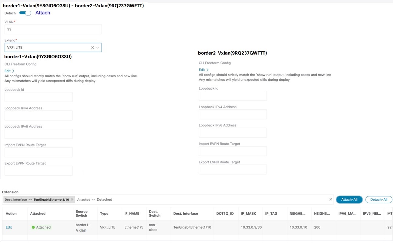
  • If the device in the External fabric is non-Nexus, you must create IFC manually.

  • Ensure that no user policy is enabled on the interface that connects to the edge router. If a policy exists, then the interface will not be configured.

  • Autoconfiguration is supported for the following cases:

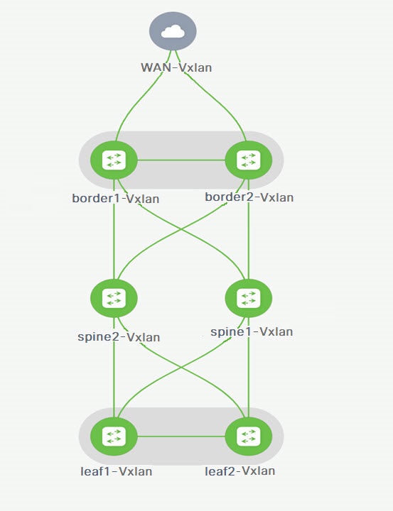
    • Border role in the VXLAN fabric and Edge Router role in the connected external fabric device

    • Border Gateway role in the VXLAN fabric and Edge Router role in the connected external fabric device

    • Border role to another Border role directly


    Note


    Autoconfiguration is not provided between two Border Gateways (BGWs).


    If VRF Lite is required between other roles, you must deploy it manually on the NDFC Web UI.

  • To deploy configurations in the external fabric, you must uncheck the Fabric Monitor Mode check box in the external fabric settings. When an external fabric is set to Fabric Monitor Mode Only, you cannot deploy configurations on the switches.

Easy Fabric Settings

The following are the 2 modes in which you can deploy VRF Lite. By default, VRF Lite deployment is set to Manual. You can change the settings based on your requirement.

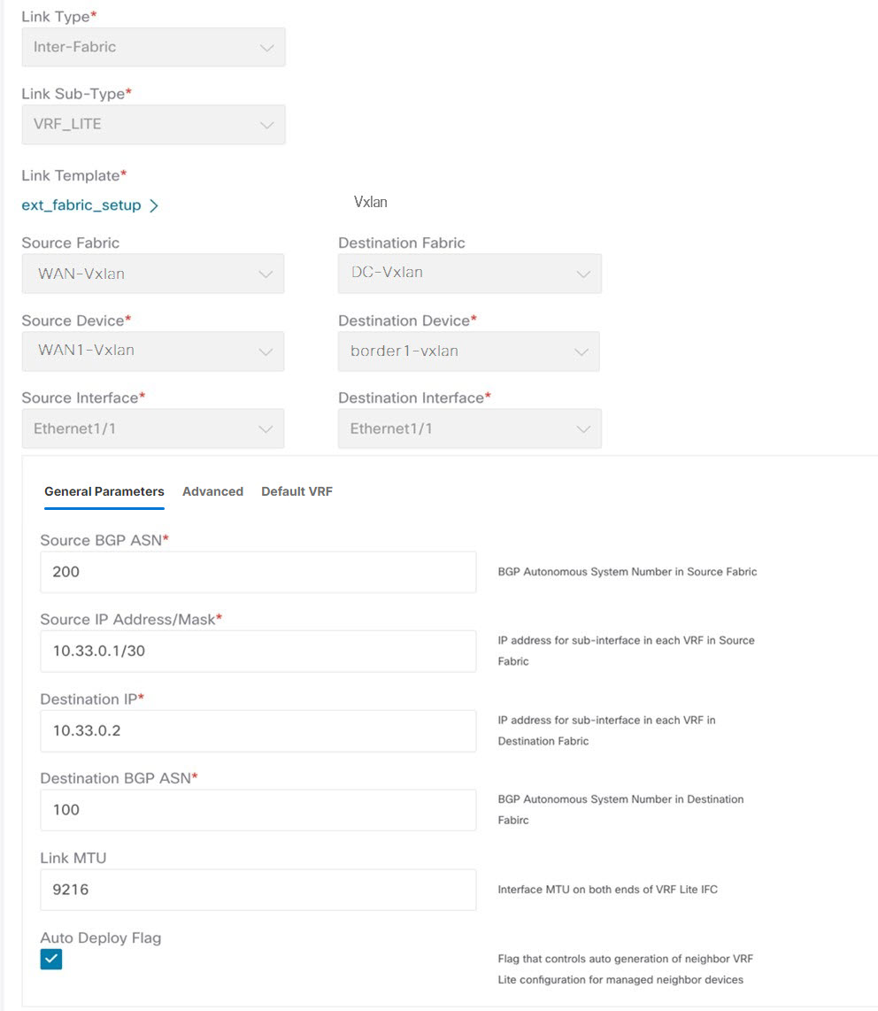
  • Manual - Use this option to deploy the VRF Lite IFCs manually between the source and the destination devices.

  • Back2Back&ToExternal - Use this option to automatically configure VRF Lite IFCs between a border switch and the edge or core switches in external fabric or between back-to-back border switches in VXLAN EVPN fabric.


Note


Though VRF Lite mode is set to Manual for NDFC resource handling, Data Center Interconnectivity (DCI) subnet is required.


The Manual mode is the default mode in fabric settings. To change the default mode to other mode, click Edit fabric settings. On Resource tab, modify VRF Lite Deployment field to the above mentioned auto configuration modes.

Auto Deploy Peer - This check box is applicable for VRF Lite deployment. When you check this check box, IFCs are automatically created for peer devices. You can check or uncheck this check box when the VRF Lite Deployment field is not set to Manual. The value you choose takes priority. This configuration only affects the new auto-created IFCs and does not affect the existing IFCs.

Auto Deploy Default VRF – When you select this check box, the Auto Generate Configuration on default VRF field is automatically enabled for auto-created VRF Lite IFCs. You can check or uncheck this checkbox when the VRF Lite Deployment field is not set to Manual. The Auto Generate Configuration on default VRF field when set, automatically configures the physical interface for the border device in the default VRF, and establishes an EBGP connection between the border device and the edge device or another border device in a different VXLAN EVPN fabric.

Auto Deploy Default VRF for Peer – When you select this checkbox, the Auto Generate Configuration for NX-OS Peer on default VRF field is automatically enabled for auto-created VRF Lite IFCs. You can check or uncheck this checkbox when the VRF Lite Deployment field is not set to Manual. The Auto Generate Configuration for NX-OS Peer on default VRF field when set, automatically configures the physical interface and the EBGP commands for the peer NX-OS switch.


Note


You can access the Auto Generate Configuration on default VRF and Auto Generate Configuration for NX-OS Peer on default VRF fields for an IFC link by navigating to Actions > Edit > VRF Lite.


Redistribute BGP Route-map Name – Defines the route map for redistributing the BGP routes in default VRF.

VRF Lite Subnet IP Range: The IP address for VRF Lite IFC deployment is chosen from this range. The default value is 10.33.0.0/16. Ensure that each fabric has its own unique range and is distinct from any underlay range to avoid possible duplication. These addresses are reserved with the Resource Manager.

VRF Lite Subnet Mask: By default, it is set to /30, which is a best practice for point-to-point (P2P) links.

VRF Lite Between Cisco Nexus 9000 Based Border and Cisco Nexus 9000 Based Edge Router

DC-Vxlan VXLAN EVPN Fabric is connected to WAN-Vxlan cloud. In the following topology, you can view WAN-Vxlan. The easy fabric has border leaf role and WAN-Vxlan cloud has a device with role edge router. NDFC shows physical and logical representation of the topology with CDP/LLDP Link discovery.

topology

In this example, you can enable VRF Lite connections between DC-Vxlan border leaf and WAN-Vxlan edge router.

For VRF Lite configuration, you must enable External Border Gateway Protocol (EBGP) peering between the fabric’s border interfaces and the edge router’s interfaces, through point-to-point (P2P) connections.

The border physical interfaces are:

  • eth1/1 on border1-Vxlan, toward eth1/1 on WAN1-Vxlan.

  • eth1/2 on border2-Vxlan, toward eth1/2 on WAN1-Vxlan.

  1. Verify the links between the border and the edge router. Choose LAN > Fabrics, double-click on DC-Vxlan fabric.

    On Fabric Overview window, click Links tab. You can view that the links that are detected by NDFC and ext_fabric_setup policy are assigned automatically.

    fab-overview
  2. Perform the following to verify the VRF Lite configuration:

    1. Select the fabric name and choose Actions > Edit.

    2. Click appropriate Links, choose Actions > Edit.

    3. Link Type – Specifies the Interfabric link between two different fabrics within NDFC.

    4. Link Sub-Type – Specifies the subtype of link. By default, the VRF_LITE option is displayed.

    5. Link Template – Specifies the template for the link. The default template for a VRF Lite IFC is ext_fabric_setup is displayed. The template enables the source and destination interfaces as Layer 3 interfaces, figures the no shutdown command, and sets their MTU to 9216.

      The Source and Destination Fabric, Device, and Interfaces are autodetected and chosen by NDFC based on CDP/LLDP discovery.

    6. On the General Parameters tabs, the fields in this tab are:

      • Source BGP ASN – BGP ASN of selected source fabric

      • Source IP Address/Mask - NDFC auto allocated IP pool from Resource Manager Pool of VRF Lite subnet Pool for the Ethernet1/1 subinterfaces, the source interface of the IFC. A subinterface is created for each VRF extended over this IFC, and a unique 802.1Q ID is assigned to it. The IP address/Mask entered here, along with the BGP Neighbor IP field (explained below) will be used as the default values for the subinterface that is created at VRF extension and can be overwritten.

        For example, an 802.1Q ID of 2 is associated with subinterface Eth 1/1.2 for VRF CORP traffic, and 802.1Q ID of 3 is associated with Eth 1/1.3 and VRF ENG, and so on.

        The IP prefix is reserved with the NDFC resource manager. Ensure that we use a unique IP address prefix for each IFC we create in the topology.

      • Destination IP - NDFC auto allocated IP pool from resource manager pool of VRF Lite subnet pool. This is a BGP neighbor IP on the device.

        Interfabric traffic from different VRFs for an IFC 's the same source IP address (10.33.0.1/30) and destination IP address (10.33.0.2) as an example.

      • Destination BGP ASN – BGP ASN of selected Destination fabric

      • Link MTU – Default 9216

      • Auto Deploy Flag – Default Auto selected based on fabric settings. This knob autoconfigures the neighbor VRF on neighboring managed device. For example, it will automatically create VRF on the edge router inside WAN-Vxlan External fabric.

    7. The Advanced tab is added in the Link Profile section. The fields in this tab are:

      • Source Interface Description

      • Destination Interface Description

      • Source Interface Freeform Config

      • Destination Interface Freeform Config

    8. Enter the following details in the Default VRF tab.

      • Auto Generate Configuration on default VRF: Automatically configures the physical interface for the border device in default VRF. Establishes an EBGP connection between the border device and its peer in the VRF LITE IFC (edge router or another border device in a different VXLAN EVPN fabric).

      • Auto Generate Configuration for NX-OS Peer on default VRF: Automatically configures the physical interface and the BGP commands for the NX-OS peer switch corresponding to default VRF.

      • Redistribute BGP Route-map Name: Defines the route map used for redistributing the BGP routes in default VRF.

      • Default VRF BGP Neighbor Password: Allows you to provide additional security by specifying a password for the BGP neighbor.

      • Default VRF BGP Password Key Encryption Type: Specifies the encryption type for the password.

      • VRF Name in NX-OS Peer Switch: Enables you to provide a name for the VRF in the peer switch. By default, the peer device is configured with default VRF, if left blank.

      • Enable DCI tracking: Enables Data Center Interconnectivity (DCI) tracking on the physical interface, which allows you to use an existing VRF Lite link as the VXLAN EVPN multi-site underlay link. Note that you must enable this option only on a border gateway device.

      • Routing TAG: Specifies the routing tag associated with the interface IP.


      Note


      All the configuration changes made to the devices as a result of the above configurations are displayed in the Pending Config window.


    9. Click Save to save the configuration.

  3. To attach VRF and VRF Lite extensions on the border devices:

    1. Click VRFs > VRF Attachments tab.

    2. Choose VRF Name, click Actions > Edit.

      The Edit window appears.

    3. You can edit details in Extension field as mentioned below:

      • Toggle the knob to Attach.

      • In Extend, choose VRF_LITE from the drop-down list.

      • On Extension card, choose one switch at a time, click Edit, enter details for PEER_VRF_NAME. This auto deploys the VRF on the neighboring device.

    When you extend VRF Lite consecutive scenario, the VRF must be in the peer fabric and VRF name must be same. If the VRF is not in the peer fabric and if you try to extend VRF Lite, an error message is generated displaying the issue.

    When you extend VRF Lite between an easy fabric and an external fabric, the VRF name can be same as name of source fabric, or default name, or another VRF name. Enter required VRF name in PEER_VRF_NAME field. The child PTIs for subinterface, VRF creation and BGP peering on external fabric have source values that are populated in it, hence the policies cannot be edited or deleted.

    Follow above procedure for other links.

    On Edit window, click Attach-All, to attach the required VRF Extension on the border devices, and then click Save.

  4. To Recalculate and deploy configurations on VXLAN EVPN Easy Fabric:

    On Fabric windows double-click on appropriate fabric to navigate to Fabric Overview window. Click Actions > Recalculate & Deploy.

    Similarly, you can also perform operation, choose required VRF Name on VRF attachments tab, click Actions > Deploy to initiate VRF and VRF Lite configurations on the border devices.

  5. To Recalculate and Deploy VXLAN EVPN Easy fabric:

    On Fabric window, click Action > Recalculate and Deploy.

    Similarly, you can choose the VRF attachments, edit, and click Deploy. It pushes VRF and VRF Lite configurations the border devices.

  6. To recalculate and deploy configurations on external fabric, choose external fabric and follow the above procedure.

VRF Lite Between Cisco Nexus 9000 Based Border and Non-Cisco Device

This example displays the procedure to enable VRF Lite connections between the DC-VXLAN border leaf device and a non-Cisco device in external fabric.

It is recommended to use meta definition of a device instead of importing devices in external fabric. This allows VRF Lite configurations to extend Cisco Nexus 9000 managed border devices in easy fabric. NDFC will not manage destination non-Cisco device. You must configure relevant VRF Lite configuration on the destination device.

  1. To create new IFC links between border and edge router.

    1. On Fabrics window, double-click the fabric.

      The Fabric Overview window appears.

    2. Navigate to Links tab. On Links tab, click Actions > Create a new link.

      The Create New link window appears.

    3. Enter the following required parameters in the window:

      • Link Type – Select the Interfabric link. This is the IFC between two different fabrics within NDFC.

      • Link Sub-Type - By default, the VRF_LITE option is displayed.

      • Link Template – The default template for a VRF Lite IFC, ext_fabric_setup, is displayed. The template enables the source and destination interfaces as Layer 3 interfaces, configures the no shutdown command, and sets their MTU to 9216.

      • Source Fabric – Select the Source Fabric. This is the Easy fabric where Cisco Nexus 9000 based border device resides.

      • Destination Fabric – Select any External or Classic LAN fabric. It can be monitor mode as well.

      • Source Device – Select the Source Device. This is the Cisco Nexus 9000 based border device.

      • Destination Device – Now, you can create a “meta device definition”. Type any name and click create. For example, non-cisco.

      • Source Interface – Select the interface on the border device where the non-cisco device is connected.

      • Destination Interface – Now, you can create a “meta device interface”. Type any interface name and click create. For example, gig1, tengig1/10, eth1/1 are the valid interface names.

      The General Parameters tab has the following fields:

      • Source BGP ASN – BGP ASN of selected Source fabric.

      • Source IP Address/Mask - Provide IP address and mask for the Ethernet1/5 subinterfaces, the source interface of the IFC. Subinterface is created for each VRF extended over this IFC, and a unique 802.1Q ID is assigned to it. The IP address/Mask entered here, along with the BGP Neighbor IP field (explained below) used as the default values for the subinterface that is created at VRF extension and can be overwritten.

        For example, an 802.1Q ID of 2 is associated with subinterface Eth 1/5.2 for VRF CORP traffic, and 802.1Q ID of 3 is associated with Eth 1/5.3 and VRF ENG, and so on.

        The IP prefix is reserved with the NDFC resource manager. Ensure that we use a unique IP address prefix for each IFC we create in the topology.

      • Destination IP - NDFC auto allocated IP pool from Resource Manager Pool of VRF Lite subnet Pool. It is a BGP neighbor IP on the device.

        Interfabric traffic from different VRFs for an IFCs the same source IP address (10.33.0.1/30) and destination IP address (10.33.0.2) as an example.

      • Destination BGP ASN – BGP ASN of selected Destination fabric

      • Link MTU – Default 9216

      • Auto Deploy Flag – Not applicable as the destination device is Non-Nexus and Non-Cisco.

      Enter the appropriate details in the Advanced tab. The following mentioned fields are in the tab:

      • Source Interface Description

      • Destination Interface Description

      • Source Interface Freeform Config

      • Destination Interface Freeform Config

      • Template for Configuration Generation on Peer

      Enter the following details in the Default VRF tab.

      • Auto Generate Configuration on default VRF: Automatically configures the physical interface for the border device in default VRF. Establishes an EBGP connection between the border device and its peer in the VRF Lite IFC (edge router or another border device in a different VXLAN EVPN fabric).

      • Auto Generate Configuration for NX-OS Peer on default VRF: This is not applicable as the peer is a non NX-OS device.

      • Redistribute BGP Route-map Name: Defines the route map used for redistributing the BGP routes in default VRF.

      • Default VRF BGP Neighbor Password: Allows you to provide additional security by specifying a password for the BGP neighbor.

      • Default VRF BGP Password Key Encryption Type: Specifies the encryption type for the password.

      • VRF Name in NX-OS Peer Switch: Enables you to provide a name for the VRF in the peer switch. By default, the peer device is configured with default VRF, if left blank.

      • Enable DCI tracking: Enables Data Center Interconnectivity (DCI) tracking on the physical interface, which allows you to use an existing VRF link as the VXLAN EVPN multi-site underlay link. Note that you must enable this option only on a border gateway device.

      • Routing TAG: Specifies the routing tag associated with the interface IP.


      Note


      All the configuration changes made to the devices as a result of the above configurations are displayed in the Pending Config window.


  2. Click Save to create new link with parameters mentioned.

  3. To attach VRF and VRF Lite extensions on the border devices, double-click on DC-Vxlan fabric. On Fabric Overview window, navigate to VRFs > VRF Attachments and edit the details as shown in the following image.

    Click Attach-all to attach the required VRF Extension on the border devices and then click Save.

  4. To recalculate and deploy configurations on VXLAN EVPN Easy fabric, click appropriate fabric on Fabric window.

    On Fabric Overview window, click Actions > Recalculate & Deploy, or navigate to VRF > VRF attachments, choose the VRF attachments, edit, and then click Deploy. This initiates the VRF and VRF Lite configurations on the border devices.

VRF Lite Between Cisco Nexus 9000 Based Border and Non-Nexus Device

In this example, you can enable VRF Lite connections between DC-Vxlan border leaf and a non-Nexus device in an external fabric.

Before Cisco NDFC Release 12.0.1a, ASR 9000 was supported for external fabric in monitor mode only. From Release 12.0.1a, ASR 9000 is supported in managed mode with an edge router role.

The following are the supported platforms:

  • ASR 9000

  • NCS 5500

  • ASR 8000

Configuration compliance is enabled for IOS-XR switches in external fabric, similar to Cisco Nexus switches configured on external fabric. NDFC pushes configuration at the end of deployment


Note


Ensure that the VXLAN BGP EVPN border device is active.


Procedure


Step 1

Navigate to LAN > Fabrics to create external fabric.

Step 2

On Create Fabric window, enter appropriate ASN number, uncheck monitor mode check box, and then click Save.

Step 3

Navigate to Switches window, click Actions > Add switches.

Note


Ensure that the IOS-XR device has the IP address reachability to NDFC with SNMP configurations for discovery.

To add non-Nexus devices to external fabrics, see Adding Non-Nexus Devices to External Fabrics.

Step 4

On Add Switches window, choose Discover check box, and IOS-XR from drop-down list for Device Type field.

Step 5

After the router is discovered, you can view the switch name in the Discovery Results field.

Step 6

Choose the discovered router and add to fabric. Ensure that the Discovery Status displays OK in the status column. Edge router role is supported.

After successful discovery, you can view the links between the devices in the Links tab.

Step 7

To create VRF Lite IFC for external fabric with Cisco Nexus 9000 border leaf, choose the link and click Actions > Edit.

Step 8

On Edit Link window, fill the required details for IFC creation. Few fields are auto-populated.

Note


For non-NX-OS device auto, deploy flag is not applicable.

Step 9

To extend VRF Lite configurations on VXLAN border device, navigate to VRF > VRF Attachment tab, choose the VRF name, click Actions > Edit and then extend it as VRF Lite.

Step 10

Deploy the configuration on VXLAN border device.

Step 11

Navigate to the fabrics window, ensure that the external fabric has the router, click Apply to VRF Lite BGP policies.

Step 12

Navigate to Policies tab, and add policies ios_xr_base_bgp and enter required details and click Save.

Step 13

Add another policy ios_xr_Ext_VRF_Lite_Jython and enter required details and click Save

Step 14

Deploy the configurations on the IOS-XR router.


Appendix

Nexus 9000 Border device configurations

Border-Vxlan (base border configurations) generated by template ext_base_border_vrflite_11_1


switch configure terminal
switch(config)#
ip prefix-list default-route seq 5 permit 0.0.0.0/0 le 1
ip prefix-list host-route seq 5 permit 0.0.0.0/0 eq 32
route-map extcon-rmap-filter deny 10
    match ip address prefix-list default-route
route-map extcon-rmap-filter deny 20
    match ip address prefix-list host-route
route-map extcon-rmap-filter permit 1000
route-map extcon-rmap-filter-allow-host deny 10
    match ip address prefix-list default-route
route-map extcon-rmap-filter-allow-host permit 1000
ipv6 prefix-list default-route-v6 seq 5 permit 0::/0
ipv6 prefix-list host-route-v6 seq 5 permit 0::/0 eq 128
route-map extcon-rmap-filter-v6 deny 10
    match ipv6 address prefix-list default-route-v6
route-map extcon-rmap-filter-v6 deny 20
    match ip address prefix-list host-route-v6
route-map extcon-rmap-filter-v6 permit 1000
route-map extcon-rmap-filter-v6-allow-host deny 10
    match ipv6 address prefix-list default-route-v6
route-map extcon-rmap-filter-v6-allow-host permit 1000

Border-Vxlan VRF Lite Extension configuration


switch configure terminal
vrf context CORP
  ip route 0.0.0.0/0 2.2.2.2
exit
router bgp 100
  vrf CORP
    address-family ipv4 unicast
      network 0.0.0.0/0
      exit
    neighbor 2.2.2.2
      remote-as 200
      address-family ipv4 unicast
        send-community both
        route-map extcon-rmap-filter out
configure terminal
interface ethernet1/1.2
  encapsulation dot1q 2
  mtu 9216
  vrf member CORP
  ip address 2.2.2.22/24
  no shutdown
configure terminal

WAN-Vxlan (External fabric Edge Router) VRF Lite Extension configuration


switch configure terminal 
vrf context CORP
  address-family ipv4 unicast
exit
router bgp 200
  vrf CORP
    address-family ipv4 unicast
    neighbor 10.33.0.2
      remote-as 100
      address-family ipv4 unicast
        send-community both
        exit
      exit
    neighbor 10.33.0.6
      remote-as 100
      address-family ipv4 unicast
        send-community both
configure terminal
interface ethernet1/1.2
  mtu 9216
  vrf member CORP
  encapsulation dot1q 2
  ip address 10.33.0.1/30
  no shutdown
interface ethernet1/2.2
  vrf member CORP
  mtu 9216
  encapsulation dot1q 2
  ip address 10.33.0.5/30
  no shutdown
configure terminal