Fabrics

LAN Fabrics

The following terms are referred to in this document:

  • Greenfield Deployments: Applicable for provisioning new VXLAN EVPN fabrics and eBGP-based routed fabrics.

  • Brownfield Deployments: Applicable for existing VXLAN EVPN fabrics:

    • Migrate CLI-configured VXLAN EVPN fabrics to Nexus Dashboard Fabric Controller using the Data Center VXLAN EVPN fabric template.

    • NFM migration to Cisco Nexus Dashboard Fabric Controller using the Data Center VXLAN EVPN fabric template.

Note that in this document the terms switch and device are used interchangeably.

For information about upgrades, refer to the Cisco Nexus Dashboard Fabric Controller Installation and Upgrade Guide for LAN Controller Deployment.

The following table describes the fields that appear on LAN > Fabrics.

Field

Description

Fabric Name

Displays the name of the fabric.

Fabric Technology

Displays the fabric technology based on the fabric template.

Fabric Type

Displays the type of the fabric—Switch Fabric, LAN Monitor, or External

ASN

Displays the ASN for the fabric.

Fabric Health

Displays the health of the fabric.

The following table describes the action items in the Actions menu drop‐down list, that appear on LAN > Fabrics.

Action Item

Description

Create Fabric

From the Actions drop-down list, select Create Fabric. For more instructions, see Create a Fabric.

Edit Fabric

Select a fabric to edit. From the Actions drop-down list, select Edit Fabric. Make the necessary changes and click Save. Click Close to discard the changes.

Delete Fabric

Select a fabric to delete. From the drop-down list, select Delete Fabric. Click Confirm to delete the fabric.

Fabric Summary

Click on a fabric to open the side kick panel. The following sections display the summary of the fabric:

  • Health - Shows the health of the Fabric.

  • Alarms - Displays the alarms based on the categories.

  • Fabric Info - Provides basic about the Fabric.

  • Inventory - Provides information about Switch Configuration and Switch Health.

Click the Launch icon to the right top corner to view the Fabric Overview.

Understanding Fabric Templates

Fabric Templates

The following table provides information about the available fabric templates:


Note


Enhanced Classic LAN is a preview feature in Nexus Dashboard Fabric Controller, Release 12.1.2e. We recommend that you use this feature marked as BETA in your lab setup only. Do not use this features in your production deployment.

To view Enhanced Classic LAN fabrics, you must enable this feature. On Web UI, navigate to Settings > Server Settings > LAN-Fabric, then check the Enable Preview Features check box.


Type of Fabric Description REST API Template Name Detailed Procedures
Data Center VXLAN EVPN Fabric for a VXLAN EVPN deployment with Nexus 9000 and 3000 switches. Easy_Fabric Creating a VXLAN EVPN Fabric Using the Data Center VXLAN EVPN Template
Enhanced Classic LAN Fabric for a fully automated 3-tier Classic LAN deployment with Nexus 9000 and 7000 switches. Easy_Fabric_Classic LAN Fabrics
Campus VXLAN EVPN Fabric for a VXLAN EVPN Campus deployment with Catalyst 9000 switches. Easy_Fabric_IOS_XE Create Data Center VXLAN EVPN for Cisco Catalyst 9000 Series Switches
BGP Fabric Fabric for an eBGP based deployment with Nexus 9000 and 3000 switches. Optionally VXLAN EVPN can be enabled on top of the eBGP underlay. Easy_Fabric_eBGP Creating VXLAN EVPN Fabric with eBGP-based Underlay
Flexible Network Fabric for flexible deployments with a mix of Nexus and Non-Nexus devices. External_Fabric Creating an External Fabric
Fabric Group Domain that can contain Enhanced Classic LAN, Classic LAN, and External Connectivity Network fabrics. Fabric_Group LAN Fabrics
Classic LAN Fabric to manage a legacy Classic LAN deployment with Nexus switches. LAN_Classic LAN Fabrics
LAN Monitor Fabric for monitoring Nexus switches for basic discovery and inventory management. LAN_Monitor LAN Fabrics
VXLAN EVPN Multi-Site Domain that can contain multiple VXLAN EVPN Fabrics (with Layer-2/Layer-3 Overlay Extensions) and other Fabric Types. MSD_Fabric Creating the VXLAN EVPN Multi-Site and Associating Member Fabrics
Classic IPFM Fabric to manage or monitor existing Nexus 9000 switches in an IP Fabric for Media Deployment. IPFM_Classic Creating a Classic IPFM Fabric
IPFM Fabric for a fully automated deployment of IP Fabric for Media Network with Nexus 9000 switches. Easy_Fabric_IPFM Creating an IPFM Fabric
Multi-Site Interconnect Network Fabric to interconnect VXLAN EVPN for Multi-Site deployments with a mix of Nexus and Non-Nexus devices External_Fabric Creating an External Fabric
External Connectivity Network Fabric for core and edge router deployments with a mix of Nexus and Non-Nexus devices. External_Fabric Creating an External Fabric

Note


Any reference to External_Fabric in this document refers to one of the following 3 fabric templates. Choose the required fabric based on the description in the above table.

  • Multi-Site Interconnect Network

  • External Connectivity Network

  • Flexible Network


The type of fabric will be seen as External_Fabric aka the fabric template name, in the following cases:

  1. Upgrade and Restore from DCNM 11.5(4) .

  2. Upgrade from NDFC 12.0.2f/12.1.1e

All existing functionalists will continue to work similarly to the previous release. You can optionally edit the fabric and choose one of the three options Flexible Network, External Connectivity Network, Multi-Site Interconnect Network. If you edit the fabric settings without choosing one of these options, then the default option Flexible Network will be picked. You can toggle between these three options as desired without any loss of functionality. The type of fabric is stored in nvPairs in a variable called EXT_FABRIC_TYPE. This can be optionally provided in the payload during fabric creation. If not provided, the default option of Flexible Network is picked.

Prerequisites to Creating a Fabric

  • From Cisco NDFC Release 12.1.2e, the ESXi host default setting on the vSphere Client for promiscuous mode is supported. For more information, see ESXi Networking for Promiscuous Mode section. From Nexus Dashboard release 2.3.1c, the vNIC of the POD that has the Persistent IP shares the same MAC address of Nexus Dashboard bond0 or bond1 interface. Therefore, the POD sources the packets using the same MAC address of Nexus Dashboard bond0 or bond1 interfaces that are known by the VMware ESXi system.

  • Configure the persistent IP addresses in Cisco Nexus Dashboard. For more information, see Cluster Configuration section in Cisco Nexus Dashboard User Guide.

Changing Persistent IP Address

From Cisco NDFC Release 12.1.2e, you can change persistent IP addresses which are assigned for mandatory pods such as POAP-SCP and SNMP trap. To change the persistent IP address, perform the following steps:

Procedure

Step 1

On Cisco NDFC Web UI, navigate to Settings > Server Settings > Admin under LAN Device Management Connectivity drop-down list change Management to Data or conversely.

Changing option results in migration of SNMP and POAP-SCP pods to the persistent IP addresses associated with External Service Pool on Nexus Dashboard connected with the new LAN Device Management Connectivity option. After the completion of this process, the following message is displayed:

Some features have been updated. Reload the page to see latest changes.

Click Reload the page.

Step 2

On Cisco Nexus Dashboard Web UI, navigate to Infrastructure > Cluster Configuration > General, in External Service Pools card, change the required IP addresses for Management Service IP Usage or Data Service IP Usage.

Step 3

Navigate to NDFC Web UI Server Settings page, change the option in LAN Device Management Connectivity drop-down list to its initial selection.

Restoring this option to initial settings, results in migration of the SNMP and POAP-SCP pods to use the updated persistent IP address from the appropriate External Service IP pool.


ESXi Networking for Promiscuous Mode

From Cisco NDFC Release 12.1.2e, you can run NDFC on top of virtual Nexus Dashboard (vND) instance with promiscuous mode that is disabled on port groups that are associated with Nexus Dashboard interfaces where External Service IP addresses are specified. vND comprises Nexus Dashboard management interface and data interface. By default, for fabric controller persona, two external service IP addresses are required for the Nexus Dashboard management interface subnet.

Before the NDFC Release 12.1.2e, if Inband management or Endpoint Locator or POAP feature was enabled on NDFC, you must also enable promiscuous mode for the Nexus Dashboard data or fabric interface port-group. This setting was mandatory for traffic flow that is associated for these features.

Enabling promiscuous mode raise risk of security issues in NDFC, it is recommended to set default setting for promiscuous mode.


Note


  • Disabling promiscuous mode is supported from Cisco Nexus Dashboard Release 2.3.1c.

  • You can disable promiscuous mode when Nexus Dashboard nodes are layer-3 adjacent on the Data network, BGP is configured, and fabric switches are reachable through the data interface.

  • You can disable promiscuous mode when Nexus Dashboard interfaces are layer-2 adjacent to switch mgmt0 interface.


If Inband management or EPL is enabled, you must specify External Service IP addresses in the Nexus Dashboard data interface subnet. You can disable promiscuous mode for the Nexus Dashboard data or fabric interface port-group. For more information, refer to Cisco Nexus Dashboard Deployment Guide


Note


Default option for promiscuous mode is Reject.


Procedure


Step 1

Log into your vSphere Client.

Step 2

Navigate to the ESXi host.

Step 3

Right-click the host and choose Settings.

A sub-menu appears.

Step 4

Choose Networking > Virtual Switches.

All the virtual switches appear as blocks.

Step 5

Click Edit Settings of the VM Network.

Step 6

Navigate to the Security tab.

Step 7

Update the Promiscuous mode settings as follows:

  • Check the Override check box.

  • Choose Accept from the drop-down list.

Step 8

Click OK.


Create a Fabric

To create a Fabric using Cisco Nexus Dashboard Fabric Controller Web UI, perform the following steps:

Procedure


Step 1

Choose LAN > Fabrics.

Step 2

From the Actions drop-down list, select Create Fabric.

Step 3

Enter the fabric name and click Choose Template.

Step 4

Specify the values for the fabric settings and click Save.


VXLAN EVPN Fabrics Provisioning

Cisco Nexus Dashboard Fabric Controller provides an enhanced “Easy” fabric workflow for unified underlay and overlay provisioning of the VXLAN BGP EVPN configuration on Nexus 9000 and 3000 series of switches. The configuration of the fabric is achieved via a powerful, flexible, and customizable template-based framework. Using minimal user inputs, an entire fabric can be brought up with Cisco-recommended best practice configurations in a short period of time. The set of parameters exposed in the Fabric Settings allow you to tailor the fabric to your preferred underlay provisioning options.

Border devices in a fabric typically provide external connectivity via peering with appropriate edge/core/WAN routers. These edge/core routers may either be managed or monitored by Nexus Dashboard Fabric Controller. These devices are placed in a special fabric called the External Fabric. The same Nexus Dashboard Fabric Controller can manage multiple VXLAN BGP EVPN fabrics while also offering easy provisioning and management of Layer-2 and Layer-3 DCI underlay and overlay configuration among these fabrics using a special construct called a Multi-Site Domain (MSD) fabric.

The Nexus Dashboard Fabric Controller GUI functions for creating and deploying VXLAN BGP EVPN fabrics are as follows:

LAN > Fabrics > LAN Fabrics Create Fabric under Actions drop-down list.

Create, edit, and delete a fabric:

  • Create new VXLAN, MSD, and external VXLAN fabrics.

  • View the VXLAN and MSD fabric topologies, including connections between fabrics.

  • Update fabric settings.

  • Save and deploy updated changes.

  • Delete a fabric (if devices are removed).

Device discovery and provisioning start-up configurations on new switches:

  • Add switch instances to the fabric.

  • Provision start-up configurations and an IP address to a new switch through POAP configuration.

  • Update switch policies, save, and deploy updated changes.

  • Create intra-fabric and inter-fabric links (also called Inter-Fabric Connections [IFCs]).

LAN > Interfaces > LAN Fabrics Create New Interface under Actions drop-down list.

Underlay provisioning:

  • Create, deploy, view, edit, and delete a port-channel, vPC switch pair, Straight Through FEX (ST-FEX), Active-Active FEX (AA-FEX), loopback, subinterface, etc.

  • Create breakout and unbreakout ports.

  • Shut down and bring up interfaces.

  • Rediscover ports and view interface configuration history.

LAN > Switches > LAN Fabrics Add under Actions drop-down list.

Overlay network provisioning.

  • Create new overlay networks and VRFs (from the range specified in fabric creation).

  • Provision the overlay networks and VRFs on the switches of the fabric.

  • Undeploy the networks and VRFs from the switches.

  • Remove the provisioning from the fabric in Nexus Dashboard Fabric Controller.

LAN > Services menu option.

Provisioning of configuration on service leafs to which L4-7 service appliances may be attached. For more information, see L4-L7 Service Basic Workflow.

This chapter mostly covers configuration provisioning for a single VXLAN BGP EVPN fabric. EVPN Multi-Site provisioning for Layer-2/Layer-3 DCI across multiple fabrics using the MSD fabric, is documented in a separate chapter. The deployment details of how overlay Networks and VRFs can be easily provisioned from the Fabric Controller, is covered in the Creating Networks and Creating VRFs in the Networks and VRFs sections.

Guidelines for VXLAN BGP EVPN Fabrics Provisioning

  • For any switch to be successfully imported into Nexus Dashboard Fabric Controller, the user specified for discovery/import, should have the following permissions:

    • SSH access to the switch

    • Ability to perform SNMPv3 queries

    • Ability to run the show commands including show run, show interfaces, etc.

    • Ability to execute the guestshell commands, which are prefixed by run guestshell for the Nexus Dashboard Fabric Controller tracker.

  • The switch discovery user need not have the ability to make any configuration changes on the switches. It is primarily used for read access.

  • When an invalid command is deployed by Nexus Dashboard Fabric Controller to a device, for example, a command with an invalid key chain due to an invalid entry in the fabric settings, an error is generated displaying this issue. This error is not cleared after correcting the invalid fabric entry. You need to manually clean up or delete the invalid commands to clear the error.

    Note that the fabric errors related to the command execution are automatically cleared only when the same failed command succeeds in the subsequent deployment.

  • LAN credentials are required to be set of any user that needs to be perform any write access to the device. LAN credentials need to be set on the Nexus Dashboard Fabric Controller, on a per user per device basis. When a user imports a device into the Easy Fabric, and LAN credentials are not set for that device, Nexus Dashboard Fabric Controller moves this device to a migration mode. Once the user sets the appropriate LAN credentials for that device, a subsequent Save & Deploy retriggers the device import process.

  • The Save & Deploy button triggers the intent regeneration for the entire fabric as well as a configuration compliance check for all the switches within the fabric. This button is required but not limited to the following cases:

    • A switch or a link is added, or any change in the topology

    • A change in the fabric settings that must be shared across the fabric

    • A switch is removed or deleted

    • A new vPC pairing or unpairing is done

    • A change in the role for a device

    When you click Recalculate Config, the changes in the fabric are evaluated, and the configuration for the entire fabric is generated. Click Preview Config to preview the generated configuration, and then deploy it at a fabric level. Therefore, Deploy Config can take more time depending on the size of the fabric.

    When you right-click on a switch icon, you can use the Deploy config to switches option to deploy per switch configurations. This option is a local operation for a switch, that is, the expected configuration or intent for a switch is evaluated against it’s current running configuration, and a config compliance check is performed for the switch to get the In-Sync or Out-of-Sync status. If the switch is out of sync, the user is provided with a preview of all the configurations running in that particular switch that vary from the intent defined by the user for that respective switch.

  • Persistent configuration diff is seen for the command line: system nve infra-vlan int force . The persistent diff occurs if you have deployed this command via the freeform configuration to the switch. Although the switch requires the force keyword during deployment, the running configuration that is obtained from the switch in Nexus Dashboard Fabric Controller doesn’t display the force keyword. Therefore, the system nve infra-vlan int force command always shows up as a diff.

    The intent in Nexus Dashboard Fabric Controller contains the line:

    system nve infra-vlan int force

    The running config contains the line:

    system nve infra-vlan int

    As a workaround to fix the persistent diff, edit the freeform config to remove the force keyword after the first deployment such that it is system nve infra-vlan int .

    The force keyword is required for the initial deploy and must be removed after a successful deploy. You can confirm the diff by using the Side-by-side Comparison tab in the Config Preview window.

    The persistent diff is also seen after a write erase and reload of a switch. Update the intent on Nexus Dashboard Fabric Controller to include the force keyword, and then you need to remove the force keyword after the first deployment.

  • When the switch contains the hardware access-list tcam region arp-ether 256 command, which is deprecated without the double-wide keyword, the below warning is displayed:

    WARNING: Configuring the arp-ether region without "double-wide" is deprecated and can result in silent non-vxlan packet drops. Use the "double-wide" keyword when carving TCAM space for the arp-ether region.

    Since the original hardware access-list tcam region arp-ether 256 command doesn’t match the policies in Nexus Dashboard Fabric Controller, this config is captured in the switch_freeform policy. After the hardware access-list tcam region arp-ether 256 double-wide command is pushed to the switch, the original tcam command that does not contain the double-wide keyword is removed.

    You must manually remove the hardware access-list tcam region arp-ether 256 command from the switch_freeform policy. Otherwise, config compliance shows a persistent diff.

    Here is an example of the hardware access-list command on the switch:

    
    switch(config)# show run | inc arp-ether
    switch(config)# hardware access-list tcam region arp-ether 256
    Warning: Please save config and reload the system for the configuration to take effect
    switch(config)# show run | inc arp-ether
    hardware access-list tcam region arp-ether 256
    switch(config)# 
    switch(config)# hardware access-list tcam region arp-ether 256 double-wide 
    Warning: Please save config and reload the system for the configuration to take effect
    switch(config)# show run | inc arp-ether
    hardware access-list tcam region arp-ether 256 double-wide
    

    You can see that the original tcam command is overwritten.

Creating a VXLAN EVPN Fabric Using the Data Center VXLAN EVPN Template

This topic describes how to create a new VXLAN EVPN fabric using the Data Center VXLAN EVPN template and contains descriptions for the IPv4 underlay. For information about the IPv6 underlay, see IPv6 Underlay Support for Easy Fabric.

  1. Navigate to the LAN Fabrics page:

    LAN > Fabrics

  2. Click Actions > Create Fabric.

    The Create Fabric window appears.

  3. Enter a unique name for the fabric in the Fabric Name field, then click Choose Fabric.

    A list of all available fabric templates are listed.

  4. From the available list of fabric templates, choose the Data Center VXLAN EVPN template, then click Select.

  5. Enter the necessary field values to create a fabric.

    The tabs and their fields in the screen are explained in the following sections. The overlay and underlay network parameters are included in these tabs.


    Note


    If you’re creating a standalone fabric as a potential member fabric of an MSD fabric (used for provisioning overlay networks for fabrics that are connected through EVPN Multi-Site technology), see Multi-Site Domain for VXLAN BGP EVPN Fabrics before creating the member fabric.


  6. When you have completed the necessary configurations, click Save.

    • Click on the fabric to display a summary in the slide-in pane.

    • Click on the Launch icon to display the Fabric Overview.

General Parameters

The General Parameters tab is displayed by default. The fields in this tab are described in the following table.

Field

Description

BGP ASN

Enter the BGP AS number the fabric is associated with. This must be same as existing fabric.

Enable IPv6 Underlay

Enable the IPv6 underlay feature. For information, see IPv6 Underlay Support for Easy Fabric.

Enable IPv6 Link-Local Address

Enables the IPv6 Link-Local address.

Fabric Interface Numbering

Specifies whether you want to use point-to-point (p2p) or unnumbered networks.

Underlay Subnet IP Mask

Specifies the subnet mask for the fabric interface IP addresses.

Underlay Subnet IPv6 Mask

Specifies the subnet mask for the fabric interface IPv6 addresses.

Underlay Routing Protocol

The IGP used in the fabric, OSPF, or IS-IS.

Route-Reflectors (RRs)

The number of spine switches that are used as route reflectors for transporting BGP traffic. Choose 2 or 4 from the drop-down box. The default value is 2.

To deploy spine devices as RRs, Nexus Dashboard Fabric Controller sorts the spine devices based on their serial numbers, and designates two or four spine devices as RRs. If you add more spine devices, existing RR configuration won’t change.

Increasing the count – You can increase the route reflectors from two to four at any point in time. Configurations are automatically generated on the other two spine devices designated as RRs.

Decreasing the count – When you reduce four route reflectors to two, remove the unneeded route reflector devices from the fabric. Follow these steps to reduce the count from 4 to 2.

  1. Change the value in the drop-down box to 2.

  2. Identify the spine switches designated as route reflectors.

    An instance of the rr_state policy is applied on the spine switch if it’s a route reflector. To find out if the policy is applied on the switch, right-click the switch, and choose View/edit policies. In the View/Edit Policies screen, search rr_state in the Template field. It is displayed on the screen.

  3. Delete the unneeded spine devices from the fabric (right-click the spine switch icon and choose Discovery > Remove from fabric).

    If you delete existing RR devices, the next available spine switch is selected as the replacement RR.

  4. Click Deploy Config in the fabric topology window.

You can preselect RRs and RPs before performing the first Save & Deploy operation. For more information, see Preselecting Switches as Route-Reflectors and Rendezvous-Points.

Anycast Gateway MAC

Specifies the anycast gateway MAC address.

Enable Performance Monitoring

Check the check box to enable performance monitoring.

Ensure that you do not clear interface counters from the Command Line Interface of the switches. Clearing interface counters can cause the Performance Monitor to display incorrect data for traffic utilization. If you must clear the counters and the switch has both clear counters and clear counters snmp commands (not all switches have the clear counters snmp command), ensure that you run both the main and the SNMP commands simultaneously. For example, you must run the clear counters interface ethernet slot/port command followed by the clear counters interface ethernet slot/port snmp command. This can lead to a one time spike.

What's next: Complete the configurations in another tab if necessary, or click Save when you have completed the necessary configurations for this fabric.

Replication

The fields in the Replication tab are described in the following table. Most of the fields are automatically generated based on Cisco-recommended best practice configurations, but you can update the fields if needed.

Field

Description

Replication Mode

The mode of replication that is used in the fabric for BUM (Broadcast, Unknown Unicast, Multicast) traffic. The choices are Ingress Replication or Multicast. When you choose Ingress replication, the multicast related fields get disabled.

You can change the fabric setting from one mode to the other, if no overlay profile exists for the fabric.

Multicast Group Subnet

IP address prefix used for multicast communication. A unique IP address is allocated from this group for each overlay network.

The replication mode change isn’t allowed if a policy template instance is created for the current mode. For example, if a multicast related policy is created and deployed, you can’t change the mode to Ingress.

Enable Tenant Routed Multicast (TRM)

Check the check box to enable Tenant Routed Multicast (TRM) that allows overlay multicast traffic to be supported over EVPN/MVPN in the VXLAN BGP EVPN fabric.

Default MDT Address for TRM VRFs

The multicast address for Tenant Routed Multicast traffic is populated. By default, this address is from the IP prefix specified in the Multicast Group Subnet field. When you update either field, ensure that the TRM address is chosen from the IP prefix specified in Multicast Group Subnet.

For more information, see Overview of Tenant Routed Multicast.

Rendezvous-Points

Enter the number of spine switches acting as rendezvous points.

RP mode

Choose from the two supported multicast modes of replication, ASM (for Any-Source Multicast [ASM]) or BiDir (for Bidirectional PIM [BIDIR-PIM]).

When you choose ASM, the BiDir related fields aren’t enabled. When you choose BiDir, the BiDir related fields are enabled.

Note


BIDIR-PIM is supported on Cisco's Cloud Scale Family platforms 9300-EX and 9300-FX/FX2, and software release 9.2(1) onwards.

When you create a new VRF for the fabric overlay, this address is populated in the Underlay Multicast Address field, in the Advanced tab.

Underlay RP Loopback ID

The loopback ID used for the rendezvous point (RP), for multicast protocol peering purposes in the fabric underlay.

Underlay Primary RP Loopback ID

Enabled if you choose BIDIR-PIM as the multicast mode of replication.

The primary loopback ID used for the phantom RP, for multicast protocol peering purposes in the fabric underlay.

Underlay Backup RP Loopback ID

Enabled if you choose BIDIR-PIM as the multicast mode of replication.

The secondary loopback ID used for the phantom RP, for multicast protocol peering purposes in the fabric underlay.

Underlay Second Backup RP Loopback Id

Used for the second fallback Bidir-PIM Phantom RP.

Underlay Third Backup RP Loopback Id

Used for the third fallback Bidir-PIM Phantom RP.

What's next: Complete the configurations in another tab if necessary, or click Save when you have completed the necessary configurations for this fabric.

VPC

The fields in the VPC tab are described in the following table. Most of the fields are automatically generated based on Cisco-recommended best practice configurations, but you can update the fields if needed.

Field

Description

vPC Peer Link VLAN

VLAN used for the vPC peer link SVI.

Make vPC Peer Link VLAN as Native VLAN

Enables vPC peer link VLAN as Native VLAN.

vPC Peer Keep Alive option

Choose the management or loopback option. If you want to use IP addresses assigned to the management port and the management VRF, choose management. If you use IP addresses assigned to loopback interfaces (and a non-management VRF), choose loopback.

If you use IPv6 addresses, you must use loopback IDs.

vPC Auto Recovery Time

Specifies the vPC auto recovery time-out period in seconds.

vPC Delay Restore Time

Specifies the vPC delay restore period in seconds.

vPC Peer Link Port Channel ID

Specifies the Port Channel ID for a vPC Peer Link. By default, the value in this field is 500.

vPC IPv6 ND Synchronize

Enables IPv6 Neighbor Discovery synchronization between vPC switches. The check box is enabled by default. Uncheck the check box to disable the function.

vPC advertise-pip

Select the check box to enable the Advertise PIP feature.

You can enable the advertise PIP feature on a specific vPC as well. .

Enable the same vPC Domain Id for all vPC Pairs

Enable the same vPC Domain ID for all vPC pairs. When you select this field, the vPC Domain Id field is editable.

vPC Domain Id

Specifies the vPC domain ID to be used on all vPC pairs.

vPC Domain Id Range

Specifies the vPC Domain Id range to use for new pairings.

Enable QoS for Fabric vPC-Peering

Enable QoS on spines for guaranteed delivery of vPC Fabric Peering communication. .

Note


QoS for vPC fabric peering and queuing policies options in fabric settings are mutually exclusive.

QoS Policy Name

Specifies QoS policy name that should be same on all fabric vPC peering spines. The default name is spine_qos_for_fabric_vpc_peering.

What's next: Complete the configurations in another tab if necessary, or click Save when you have completed the necessary configurations for this fabric.

Protocols

The fields in the Protocols tab are described in the following table. Most of the fields are automatically generated based on Cisco-recommended best practice configurations, but you can update the fields if needed.

Field

Description

Underlay Routing Loopback Id

The loopback interface ID is populated as 0 since loopback0 is usually used for fabric underlay IGP peering purposes.

Underlay VTEP Loopback Id

The loopback interface ID is populated as 1 since loopback1 is used for the VTEP peering purposes.

Underlay Anycast Loopback Id

The loopback interface ID is greyed out and used for vPC Peering in VXLANv6 Fabrics only.

Underlay Routing Protocol Tag

The tag defining the type of network.

OSPF Area ID

The OSPF area ID, if OSPF is used as the IGP within the fabric.

Note


The OSPF or IS-IS authentication fields are enabled based on your selection in the Underlay Routing Protocol field in the General tab.

Enable OSPF Authentication

Select the check box to enable OSPF authentication. Deselect the check box to disable it. If you enable this field, the OSPF Authentication Key ID and OSPF Authentication Key fields get enabled.

OSPF Authentication Key ID

The Key ID is populated.

OSPF Authentication Key

The OSPF authentication key must be the 3DES key from the switch.

Note

 
Plain text passwords are not supported. Log in to the switch, retrieve the encrypted key and enter it in this field. Refer, Retrieving the Authentication Key section for details.

IS-IS Level

Select the IS-IS level from this drop-down list.

Enable IS-IS Network Point-to-Point

Enables network point-to-point on fabric interfaces which are numbered.

Enable IS-IS Authentication

Select the check box to enable IS-IS authentication. Deselect the check box to disable it. If you enable this field, the IS-IS authentication fields are enabled.

IS-IS Authentication Keychain Name

Enter the Keychain name, such as CiscoisisAuth.

IS-IS Authentication Key ID

The Key ID is populated.

IS-IS Authentication Key

Enter the Cisco Type 7 encrypted key.

Note


Plain text passwords are not supported. Log in to the switch, retrieve the encrypted key and enter it in this field. Refer the Retrieving the Authentication Key section for details.

Set IS-IS Overload Bit

When enabled, set the overload bit for an elapsed time after a reload.

IS-IS Overload Bit Elapsed Time

Allows you to clear the overload bit after an elapsed time in seconds.

Enable BGP Authentication

Select the check box to enable BGP authentication. Deselect the check box to disable it. If you enable this field, the BGP Authentication Key Encryption Type and BGP Authentication Key fields are enabled.

Note

 
If you enable BGP authentication using this field, leave the iBGP Peer-Template Config field blank to avoid duplicate configuration.

BGP Authentication Key Encryption Type

Choose the 3 for 3DES encryption type, or 7 for Cisco encryption type.

BGP Authentication Key

Enter the encrypted key based on the encryption type.

Note

 
Plain text passwords are not supported. Log in to the switch, retrieve the encrypted key and enter it in the BGP Authentication Key field. Refer the Retrieving the Authentication Key section for details.

Enable PIM Hello Authentication

Select this check box to enable PIM hello authentication on all the intra-fabric interfaces of the switches in a fabric. This check box is editable only for the Multicast replication mode. Note this check box is valid only for the IPv4 underlay.

PIM Hello Authentication Key

Specifies the PIM hello authentication key. For more information, see Retrieving PIM Hello Authentication Key.

To retrieve the PIM Hello Authentication Key, perform the following steps:

  1. SSH into the switch.

  2. On an unused switch interface, enable the following:

    switch(config)# interface e1/32 
    switch(config-if)# ip pim hello-authentication ah-md5 pimHelloPassword

    In this example, pimHelloPassword is the cleartext password that has been used.

  3. Enter the show run interface command to retrieve the PIM hello authentication key.

    switch(config-if)# show run interface e1/32 | grep pim 
    ip pim sparse-mode 
    ip pim hello-authentication ah-md5 3 d34e6c5abc7fecf1caa3b588b09078e0 

    In this example, d34e6c5abc7fecf1caa3b588b09078e0 is the PIM hello authentication key that should be specified in the fabric settings.

Enable BFD

Check the check box to enable feature bfd on all switches in the fabric. This feature is valid only on IPv4 underlay and the scope is within a fabric.

BFD within a fabric is supported natively. The BFD feature is disabled by default in the Fabric Settings. If enabled, BFD is enabled for the underlay protocols with the default settings. Any custom required BFD configurations must be deployed via the per switch freeform or per interface freeform policies.

The following config is pushed after you select the Enable BFD check box:

feature bfd

For information about BFD feature compatibility, refer your respective platform documentation and for information about the supported software images, see Compatibility Matrix for Cisco Nexus Dashboard Fabric Controller.

Enable BFD for iBGP

Check the check box to enable BFD for the iBGP neighbor. This option is disabled by default.

Enable BFD for OSPF

Check the check box to enable BFD for the OSPF underlay instance. This option is disabled by default, and it is grayed out if the link state protocol is ISIS.

Enable BFD for ISIS

Check the check box to enable BFD for the ISIS underlay instance. This option is disabled by default, and it is grayed out if the link state protocol is OSPF.

Enable BFD for PIM

Check the check box to enable BFD for PIM. This option is disabled by default, and it is be grayed out if the replication mode is Ingress.

Following are examples of the BFD global policies:


router ospf <ospf tag>
   bfd

router isis <isis tag>
  address-family ipv4 unicast
    bfd

ip pim bfd

router bgp <bgp asn>
  neighbor <neighbor ip>
    bfd

Enable BFD Authentication

Check the check box to enable BFD authentication. If you enable this field, the BFD Authentication Key ID and BFD Authentication Key fields are editable.

Note


BFD Authentication is not supported when the Fabric Interface Numbering field under the General tab is set to unnumbered. The BFD authentication fields will be grayed out automatically. BFD authentication is valid for only for P2P interfaces.

BFD Authentication Key ID

Specifies the BFD authentication key ID for the interface authentication. The default value is 100.

BFD Authentication Key

Specifies the BFD authentication key.

For information about how to retrieve the BFD authentication parameters. .

iBGP Peer-Template Config

Add iBGP peer template configurations on the leaf switches to establish an iBGP session between the leaf switch and route reflector.

If you use BGP templates, add the authentication configuration within the template and uncheck the Enable BGP Authentication check box to avoid duplicate configuration.

In the sample configuration, the 3DES password is displayed after password 3.

router bgp 65000
    password 3 sd8478fswerdfw3434fsw4f4w34sdsd8478fswerdfw3434fsw4f4w

The following fields can be used to specify different configurations:

  • iBGP Peer-Template Config – Specifies the config used for RR and spines with border role.

  • Leaf/Border/Border Gateway iBGP Peer-Template Config – Specifies the config used for leaf, border, or border gateway. If this field is empty, the peer template defined in iBGP Peer-Template Config is used on all BGP enabled devices (RRs, leafs, border, or border gateway roles).

In a brownfield migration, if the spine and leaf use different peer template names, both iBGP Peer-Template Config and Leaf/Border/Border Gateway iBGP Peer-Template Config fields need to be set according to the switch config. If spine and leaf use the same peer template name and content (except for the “route-reflector-client” CLI), only iBGP Peer-Template Config field in fabric setting needs to be set. If the fabric settings on iBGP peer templates do not match the existing switch configuration, an error message is generated and the migration will not proceed.

What's next: Complete the configurations in another tab if necessary, or click Save when you have completed the necessary configurations for this fabric.

Advanced

The fields in the Advanced tab are described in the following table. Most of the fields are automatically generated based on Cisco-recommended best practice configurations, but you can update the fields if needed.

Field

Description

VRF Template

Specifies the VRF template for creating VRFs.

Network Template

Specifies the network template for creating networks.

VRF Extension Template

Specifies the VRF extension template for enabling VRF extension to other fabrics.

Network Extension Template

Specifies the network extension template for extending networks to other fabrics.

Overlay Mode

VRF/Network configuration using config-profile or CLI, default is config-profile. For more information, see Overlay Mode.

Site ID

The ID for this fabric if you are moving this fabric within an MSD. The site ID is mandatory for a member fabric to be a part of an MSD. Each member fabric of an MSD has a unique site ID for identification.

Intra Fabric Interface MTU

Specifies the MTU for the intra fabric interface. This value should be an even number.

Layer 2 Host Interface MTU

Specifies the MTU for the layer 2 host interface. This value should be an even number.

Unshut Host Interfaces by Default

Check this check box to unshut the host interfaces by default.

Power Supply Mode

Choose the appropriate power supply mode.

CoPP Profile

Choose the appropriate Control Plane Policing (CoPP) profile policy for the fabric. By default, the strict option is populated.

VTEP HoldDown Time

Specifies the NVE source interface hold down time.

Brownfield Overlay Network Name Format

Enter the format to be used to build the overlay network name during a brownfield import or migration. The network name should not contain any white spaces or special characters except underscore (_) and hyphen (-). The network name must not be changed once the brownfield migration has been initiated. See the Creating Networks for the Standalone Fabric section for the naming convention of the network name. The syntax is [<string> | $$VLAN_ID$$] $$VNI$$ [<string>| $$VLAN_ID$$] and the default value is Auto_Net_VNI$$VNI$$_VLAN$$VLAN_ID$$. When you create networks, the name is generated according to the syntax you specify.

The following list describes the variables in the syntax:

  • $$VNI$$: Specifies the network VNI ID found in the switch configuration. This is a mandatory keyword required to create unique network names.

  • $$VLAN_ID$$: Specifies the VLAN ID associated with the network.

    VLAN ID is specific to switches, hence Nexus Dashboard Fabric Controller picks the VLAN ID from one of the switches, where the network is found, randomly and use it in the name.

    We recommend not to use this unless the VLAN ID is consistent across the fabric for the VNI.

  • <string>: This variable is optional and you can enter any number of alphanumeric characters that meet the network name guidelines.

An example overlay network name: Site_VNI12345_VLAN1234

Note


Ignore this field for greenfield deployments. The Brownfield Overlay Network Name Format applies for the following brownfield imports:

  • CLI-based overlays

  • Configuration profile-based overlay

Enable CDP for Bootstrapped Switch

Enables CDP on management (mgmt0) interface for bootstrapped switch. By default, for bootstrapped switches, CDP is disabled on the mgmt0 interface.

Enable VXLAN OAM

Enables the VXLAM OAM functionality for devices in the fabric. This is enabled by default. Uncheck the check box to disable VXLAN OAM function.

If you want to enable the VXLAN OAM function on specific switches and disable on other switches in the fabric, you can use freeform configurations to enable OAM and disable OAM in the fabric settings.

Note


The VXLAN OAM feature in Cisco Nexus Dashboard Fabric Controller is only supported on a single fabric or site.

Enable Tenant DHCP

Check the check box to enable feature dhcp and associated configurations globally on all switches in the fabric. This is a pre-requisite for support of DHCP for overlay networks that are part of the tenant VRFs.

Note


Ensure that Enable Tenant DHCP is enabled before enabling DHCP-related parameters in the overlay profiles.

Enable NX-API

Specifies enabling of NX-API on HTTPS. This check box is checked by default.

Enable NX-API on HTTP Port

Specifies enabling of NX-API on HTTP. Enable this check box and the Enable NX-API check box to use HTTP. This check box is checked by default. If you uncheck this check box, the applications that use NX-API and supported by Cisco Nexus Dashboard Fabric Controller, such as Endpoint Locator (EPL), Layer 4-Layer 7 services (L4-L7 services), VXLAN OAM, and so on, start using the HTTPS instead of HTTP.

Note


If you check the Enable NX-API check box and the Enable NX-API on HTTP check box, applications use HTTP.

Enable Policy-Based Routing (PBR)

Check this check box to enable routing of packets based on the specified policy. Starting with Cisco NX-OS Release 7.0(3)I7(1) and later releases, this feature works on Cisco Nexus 9000 Series switches with Nexus 9000 Cloud Scale (Tahoe) ASICs. This feature is used along with the Layer 4-Layer 7 service workflow. For information on Layer 4-Layer 7 service, refer the Layer 4-Layer 7 Service chapter.

Enable Strict Config Compliance

Enable the Strict Config Compliance feature by selecting this check box. It enables bi-directional compliance checks to flag additional configs in the running config that are not in the intent/expected config. By default, this feature is disabled.

Enable AAA IP Authorization

Enables AAA IP authorization, when IP Authorization is enabled in the remote authentication server. This is required to support Nexus Dashboard Fabric Controller in scenarios where customers have strict control of which IP addresses can have access to the switches.

Enable NDFC as Trap Host

Select this check box to enable Nexus Dashboard Fabric Controller as an SNMP trap destination. Typically, for a native HA Nexus Dashboard Fabric Controller deployment, the eth1 VIP IP address will be configured as SNMP trap destination on the switches. By default, this check box is enabled.

Anycast Border Gateway advertise-pip

Enables to advertise Anycast Border Gateway PIP as VTEP. Effective on MSD fabric 'Recalculate Config'.

Greenfield Cleanup Option

Enable the switch cleanup option for switches imported into Nexus Dashboard Fabric Controller with Preserve-Config=No, without a switch reload. This option is typically recommended only for the fabric environments with Cisco Nexus 9000v Switches to improve on the switch clean up time. The recommended option for Greenfield deployment is to employ Bootstrap or switch cleanup with a reboot. In other words, this option should be unchecked.

Enable Precision Time Protocol (PTP)

Enables PTP across a fabric. When you check this check box, PTP is enabled globally and on core-facing interfaces. Additionally, the PTP Source Loopback Id and PTP Domain Id fields are editable. For more information, see Precision Time Protocol for Easy Fabric.

PTP Source Loopback Id

Specifies the loopback interface ID Loopback that is used as the Source IP Address for all PTP packets. The valid values range from 0 to 1023. The PTP loopback ID cannot be the same as RP, Phantom RP, NVE, or MPLS loopback ID. Otherwise, an error will be generated. The PTP loopback ID can be the same as BGP loopback or user-defined loopback which is created from Nexus Dashboard Fabric Controller.

If the PTP loopback ID is not found during Deploy Config, the following error is generated:

Loopback interface to use for PTP source IP is not found. Create PTP loopback interface on all the devices to enable PTP feature.

PTP Domain Id

Specifies the PTP domain ID on a single network. The valid values range from 0 to 127.

Enable MPLS Handoff

Check the check box to enable the MPLS Handoff feature. For more information, see the MPLS SR and LDP Handoff chapter in External/WAN Layer 3 Connectivity for VXLAN BGP EVPN Fabrics.

Underlay MPLS Loopback Id

Specifies the underlay MPLS loopback ID. The default value is 101.

Enable TCAM Allocation

TCAM commands are automatically generated for VXLAN and vPC Fabric Peering when enabled.

Enable Default Queuing Policies

Check this check box to apply QoS policies on all the switches in this fabric. To remove the QoS policies that you applied on all the switches, uncheck this check box, update all the configurations to remove the references to the policies, and save and deploy. Pre-defined QoS configurations are included that can be used for various Cisco Nexus 9000 Series Switches. When you check this check box, the appropriate QoS configurations are pushed to the switches in the fabric. The system queuing is updated when configurations are deployed to the switches. You can perform the interface marking with defined queuing policies, if required, by adding the required configuration to the per interface freeform block.

Review the actual queuing policies by opening the policy file in the template editor. From Cisco Nexus Dashboard Fabric Controller Web UI, choose Operations > Templates. Search for the queuing policies by the policy file name, for example, queuing_policy_default_8q_cloudscale. Choose the file. From the Actions drop-down list, select Edit template content to edit the policy.

See the Cisco Nexus 9000 Series NX-OS Quality of Service Configuration Guide for platform specific details.

N9K Cloud Scale Platform Queuing Policy

Choose the queuing policy from the drop-down list to be applied to all Cisco Nexus 9200 Series Switches and the Cisco Nexus 9000 Series Switches that ends with EX, FX, and FX2 in the fabric. The valid values are queuing_policy_default_4q_cloudscale and queuing_policy_default_8q_cloudscale. Use the queuing_policy_default_4q_cloudscale policy for FEXes. You can change from the queuing_policy_default_4q_cloudscale policy to the queuing_policy_default_8q_cloudscale policy only when FEXes are offline.

N9K R-Series Platform Queuing Policy

Choose the queuing policy from the drop-down list to be applied to all Cisco Nexus switches that ends with R in the fabric. The valid value is queuing_policy_default_r_series.

Other N9K Platform Queuing Policy

Choose the queuing policy from the drop-down list to be applied to all other switches in the fabric other than the switches mentioned in the above two options. The valid value is queuing_policy_default_other.

Enable MACsec

Enables MACsec for the fabric. For more information, see Enabling MACsec.

Freeform CLIs - Fabric level freeform CLIs can be added while creating or editing a fabric. They are applicable to switches across the fabric. You must add the configurations as displayed in the running configuration, without indentation. Switch level freeform configurations should be added via the switch freeform on NDFC. For more information, see Enabling Freeform Configurations on Fabric Switches.

Leaf Freeform Config

Add CLIs that should be added to switches that have the Leaf, Border, and Border Gateway roles.

Spine Freeform Config

Add CLIs that should be added to switches with a Spine, Border Spine, Border Gateway Spine, and Super Spine roles.

Intra-fabric Links Additional Config

Add CLIs that should be added to the intra-fabric links.

What's next: Complete the configurations in another tab if necessary, or click Save when you have completed the necessary configurations for this fabric.

Resources

The fields in the Resources tab are described in the following table. Most of the fields are automatically generated based on Cisco-recommended best practice configurations, but you can update the fields if needed.

Field

Description

Manual Underlay IP Address Allocation

Do not check this check box if you are transitioning your VXLAN fabric management to Nexus Dashboard Fabric Controller.

  • By default, Nexus Dashboard Fabric Controller allocates the underlay IP address resources (for loopbacks, fabric interfaces, etc) dynamically from the defined pools. If you check the check box, the allocation scheme switches to static, and some of the dynamic IP address range fields are disabled.

  • For static allocation, the underlay IP address resources must be populated into the Resource Manager (RM) using REST APIs.

  • The Underlay RP Loopback IP Range field stays enabled if BIDIR-PIM function is chosen for multicast replication.

  • Changing from static to dynamic allocation keeps the current IP resource usage intact. Only future IP address allocation requests are taken from dynamic pools.

Underlay Routing Loopback IP Range

Specifies loopback IP addresses for the protocol peering.

Underlay VTEP Loopback IP Range

Specifies loopback IP addresses for VTEPs.

Underlay RP Loopback IP Range

Specifies the anycast or phantom RP IP address range.

Underlay Subnet IP Range

IP addresses for underlay P2P routing traffic between interfaces.

Underlay MPLS Loopback IP Range

Specifies the underlay MPLS loopback IP address range.

For eBGP between Border of Easy A and Easy B, Underlay routing loopback and Underlay MPLS loopback IP range must be a unique range. It should not overlap with IP ranges of the other fabrics, else VPNv4 peering will not come up.

Underlay Routing Loopback IPv6 Range

Specifies Loopback0 IPv6 Address Range

Underlay VTEP Loopback IPv6 Range

Specifies Loopback1 and Anycast Loopback IPv6 Address Range.

Underlay Subnet IPv6 Range

Specifies IPv6 Address range to assign Numbered and Peer Link SVI IPs.

BGP Router ID Range for IPv6 Underlay

Specifies BGP router ID range for IPv6 underlay.

Layer 2 VXLAN VNI Range

Specifies the overlay VXLAN VNI range for the fabric (min:1, max:16777214).

Layer 3 VXLAN VNI Range

Specifies the overlay VRF VNI range for the fabric (min:1, max:16777214).

Network VLAN Range

VLAN range for the per switch overlay network (min:2, max:4094).

VRF VLAN Range

VLAN range for the per switch overlay Layer 3 VRF (min:2, max:4094).

Subinterface Dot1q Range

Specifies the subinterface range when L3 sub interfaces are used.

VRF Lite Deployment

Specify the VRF Lite method for extending inter fabric connections.

The VRF Lite Subnet IP Range field specifies resources reserved for IP address used for VRF Lite when VRF Lite IFCs are auto-created. If you select Back2Back&ToExternal, then VRF Lite IFCs are auto-created.

Auto Deploy for Peer

This check box is applicable for VRF Lite deployment. When you select this checkbox, auto-created VRF Lite IFCs will have the Auto Generate Configuration for Peer field in the VRF Lite tab set.

To access VRF Lite IFC configuration, navigate to the Links tab, select the particular link, and then choose Actions > Edit.

You can check or uncheck the check box when the VRF Lite Deployment field is not set to Manual. This configuration only affects the new auto-created IFCs and does not affect the existing IFCs. You can edit an auto-created IFC and check or uncheck the Auto Generate Configuration for Peer field. This setting takes priority always.

Auto Deploy Default VRF

When you select this check box, the Auto Generate Configuration on default VRF field is automatically enabled for auto-created VRF Lite IFCs. You can check or uncheck this check box when the VRF Lite Deployment field is not set to Manual. The Auto Generate Configuration on default VRF field when set, automatically configures the physical interface for the border device, and establishes an EBGP connection between the border device and the edge device or another border device in a different VXLAN EVPN fabric.

Auto Deploy Default VRF for Peer

When you select this check box, the Auto Generate Configuration for NX-OS Peer on default VRF field is automatically enabled for auto-created VRF Lite IFCs. You can check or uncheck this check box when the VRF Lite Deployment field is not set to Manual. The Auto Generate Configuration for NX-OS Peer on default VRF field when set, automatically configures the physical interface and the EBGP commands for the peer NX-OS switch.

Note


To access the Auto Generate Configuration on default VRF and Auto Generate Configuration for NX-OS Peer on default VRF fields for an IFC link, navigate to the Links tab, select the particular link and choose Actions > Edit.

Redistribute BGP Route-map Name

Defines the route map for redistributing the BGP routes in default VRF.

VRF Lite Subnet IP Range and VRF Lite Subnet Mask

These fields are populated with the DCI subnet details. Update the fields as needed.

The values shown in your screen are automatically generated. If you want to update the IP address ranges, VXLAN Layer 2/Layer 3 network ID ranges or the VRF/Network VLAN ranges, ensure the following:

Note


When you update a range of values, ensure that it does not overlap with other ranges. You should only update one range of values at a time. If you want to update more than one range of values, do it in separate instances. For example, if you want to update L2 and L3 ranges, you should do the following.

  1. Update the L2 range and click Save.

  2. Click the Edit Fabric option again, update the L3 range and click Save.

Service Network VLAN Range

Specifies a VLAN range in the Service Network VLAN Range field. This is a per switch overlay service network VLAN range. The minimum allowed value is 2 and the maximum allowed value is 3967.

Route Map Sequence Number Range

Specifies the route map sequence number range. The minimum allowed value is 1 and the maximum allowed value is 65534.

What's next: Complete the configurations in another tab if necessary, or click Save when you have completed the necessary configurations for this fabric.

Manageability

The fields in the Manageability tab are described in the following table. Most of the fields are automatically generated based on Cisco-recommended best practice configurations, but you can update the fields if needed.

Field

Description

Inband Management

Enabling this allows the management of the switches over their front panel interfaces. The Underlay Routing Loopback interface is used for discovery. If enabled, switches cannot be added to the fabric over their out-of-band (OOB) mgmt0 interface. To manage easy fabrics through Inband management ensure that you have chosen Data in NDFC Web UI, Settings > Server Settings > Admin. Both inband management and out-of-band connectivity (mgmt0) are supported for this setting. For more information, see Inband Management and Inband POAP in Easy Fabrics.

DNS Server IPs

Specifies the comma separated list of IP addresses (v4/v6) of the DNS servers.

DNS Server VRFs

Specifies one VRF for all DNS servers or a comma separated list of VRFs, one per DNS server.

NTP Server IPs

Specifies comma separated list of IP addresses (v4/v6) of the NTP server.

NTP Server VRFs

Specifies one VRF for all NTP servers or a comma separated list of VRFs, one per NTP server.

Syslog Server IPs

Specifies the comma separated list of IP addresses (v4/v6) IP address of the syslog servers, if used.

Syslog Server Severity

Specifies the comma separated list of syslog severity values, one per syslog server. The minimum value is 0 and the maximum value is 7. To specify a higher severity, enter a higher number.

Syslog Server VRFs

Specifies one VRF for all syslog servers or a comma separated list of VRFs, one per syslog server.

AAA Freeform Config

Specifies the AAA freeform configurations.

If AAA configurations are specified in the fabric settings, switch_freeform PTI with source as UNDERLAY_AAA and description as AAA Configurations will be created.

What's next: Complete the configurations in another tab if necessary, or click Save when you have completed the necessary configurations for this fabric.

Bootstrap

The fields in the Bootstrap tab are described in the following table. Most of the fields are automatically generated based on Cisco-recommended best practice configurations, but you can update the fields if needed.

Field

Description

Enable Bootstrap

Select this check box to enable the bootstrap feature. Bootstrap allows easy day-0 import and bring-up of new devices into an existing fabric. Bootstrap leverages the NX-OS POAP functionality.

Starting from Cisco NDFC Release 12.1.1e, to add more switches and for POAP capability, chose check box for Enable Bootstrap and Enable Local DHCP Server. For more information, see Inband Management and Inband POAP in Easy Fabrics

After you enable bootstrap, you can enable the DHCP server for automatic IP address assignment using one of the following methods:

  • External DHCP Server: Enter information about the external DHCP server in the Switch Mgmt Default Gateway and Switch Mgmt IP Subnet Prefix fields.

  • Local DHCP Server: Enable the Local DHCP Server check box and enter details for the remaining mandatory fields.

Enable Local DHCP Server

Select this check box to initiate enabling of automatic IP address assignment through the local DHCP server. When you select this check box, the DHCP Scope Start Address and DHCP Scope End Address fields become editable.

If you do not select this check box, Nexus Dashboard Fabric Controller uses the remote or external DHCP server for automatic IP address assignment.

DHCP Version

Select DHCPv4 or DHCPv6 from this drop-down list. When you select DHCPv4, the Switch Mgmt IPv6 Subnet Prefix field is disabled. If you select DHCPv6, the Switch Mgmt IP Subnet Prefix is disabled.

Note


Cisco Nexus 9000 and 3000 Series Switches support IPv6 POAP only when switches are either Layer-2 adjacent (eth1 or out-of-band subnet must be a /64) or they are L3 adjacent residing in some IPv6 /64 subnet. Subnet prefixes other than /64 are not supported.

DHCP Scope Start Address and DHCP Scope End Address

Specifies the first and last IP addresses of the IP address range to be used for the switch out of band POAP.

Switch Mgmt Default Gateway

Specifies the default gateway for the management VRF on the switch.

Switch Mgmt IP Subnet Prefix

Specifies the prefix for the Mgmt0 interface on the switch. The prefix should be between 8 and 30.

DHCP scope and management default gateway IP address specification - If you specify the management default gateway IP address 10.0.1.1 and subnet mask 24, ensure that the DHCP scope is within the specified subnet, between 10.0.1.2 and 10.0.1.254.

Switch Mgmt IPv6 Subnet Prefix

Specifies the IPv6 prefix for the Mgmt0 interface on the switch. The prefix should be between 112 and 126. This field is editable if you enable IPv6 for DHCP.

Enable AAA Config

Select this check box to include AAA configurations from the Manageability tab as part of the device start-up config post bootstrap.

DHCPv4/DHCPv6 Multi Subnet Scope

Specifies the field to enter one subnet scope per line. This field is editable after you check the Enable Local DHCP Server check box.

The format of the scope should be defined as:

DHCP Scope Start Address, DHCP Scope End Address, Switch Management Default Gateway, Switch Management Subnet Prefix

For example: 10.6.0.2, 10.6.0.9, 10.6.0.1, 24

Bootstrap Freeform Config

(Optional) Enter additional commands as needed. For example, if you require some additional configurations to be pushed to the device and be available post device bootstrap, they can be captured in this field, to save the desired intent. After the devices boot up, they will contain the configuration defined in the Bootstrap Freeform Config field.

Copy-paste the running-config to a freeform config field with correct indentation, as seen in the running configuration on the NX-OS switches. The freeform config must match the running config. For more information, see Enabling Freeform Configurations on Fabric Switches.

What's next: Complete the configurations in another tab if necessary, or click Save when you have completed the necessary configurations for this fabric.

Configuration Backup

The fields in the Configuration Backup tab are described in the following table. Most of the fields are automatically generated based on Cisco-recommended best practice configurations, but you can update the fields if needed.

Field

Description

Hourly Fabric Backup

Select the check box to enable an hourly backup of fabric configurations and the intent.

The hourly backups are triggered during the first 10 minutes of the hour.

Scheduled Fabric Backup

Check the check box to enable a daily backup. This backup tracks changes in running configurations on the fabric devices that are not tracked by configuration compliance.

Scheduled Time

Specify the scheduled backup time in a 24-hour format. This field is enabled if you check the Scheduled Fabric Backup check box.

Select both the check boxes to enable both back up processes.

The backup process is initiated after you click Save.

The scheduled backups are triggered exactly at the time you specify with a delay of up to two minutes. The scheduled backups are triggered regardless of the configuration deployment status.

The number of fabric backups that will be retained on NDFC is decided by the Settings > Server Settings > LAN Fabric > Maximum Backups per Fabric.

The number of archived files that can be retained is set in the # Number of archived files per device to be retained: field in the Server Properties window.

Note


To trigger an immediate backup, do the following:

  1. Choose LAN > Topology.

  2. Click within the specific fabric box. The fabric topology screen comes up.

  3. From the Actions pane at the left part of the screen, click Re-Sync Fabric.

You can also initiate the fabric backup in the fabric topology window. Click Backup Now in the Actions pane.

What's next: Complete the configurations in another tab if necessary, or click Save when you have completed the necessary configurations for this fabric.

Flow Monitor

The fields in the Flow Monitor tab are described in the following table. Most of the fields are automatically generated based on Cisco-recommended best practice configurations, but you can update the fields if needed.

Field

Description

Enable Netflow

Check this check box to enable Netflow on VTEPs for this Fabric. By default, Netflow is disabled. On Enable, NetFlow configuration will be applied to all VTEPS that support netflow.

Note


When Netflow is enabled on the fabric, you can choose not to have netflow on a particular switch by having a dummy no_netflow PTI.

If netflow is not enabled at the fabric level, an error message is generated when you enable netflow at the interface, network, or vrf level. For information about Netflow support for Cisco NDFC, refer to Netflow Support.

In the Netflow Exporter area, click Actions > Add to add one or more Netflow exporters. This exporter is the receiver of the netflow data. The fields on this screen are:

  • Exporter Name – Specifies the name of the exporter.

  • IP – Specifies the IP address of the exporter.

  • VRF – Specifies the VRF over which the exporter is routed.

  • Source Interface – Enter the source interface name.

  • UDP Port – Specifies the UDP port over which the netflow data is exported.

Click Save to configure the exporter. Click Cancel to discard. You can also choose an existing exporter and select Actions > Edit or Actions > Delete to perform relevant actions.

In the Netflow Record area, click Actions > Add to add one or more Netflow records. The fields on this screen are:

  • Record Name – Specifies the name of the record.

  • Record Template – Specifies the template for the record. Enter one of the record templates names. In Release 12.0.2, the following two record templates are available for use. You can create custom netflow record templates. Custom record templates saved in the template library are available for use here.

    • netflow_ipv4_record – to use the IPv4 record template.

    • netflow_l2_record – to use the Layer 2 record template.

  • Is Layer2 Record – Check this check box if the record is for Layer2 netflow.

Click Save to configure the report. Click Cancel to discard. You can also choose an existing record and select Actions > Edit or Actions > Delete to perform relevant actions.

In the Netflow Monitor area, click Actions > Add to add one or more Netflow monitors. The fields on this screen are:

  • Monitor Name – Specifies the name of the monitor.

  • Record Name – Specifies the name of the record for the monitor.

  • Exporter1 Name – Specifies the name of the exporter for the netflow monitor.

  • Exporter2 Name – (optional) Specifies the name of the secondary exporter for the netflow monitor.

The record name and exporters referred to in each netflow monitor must be defined in "Netflow Record" and "Netflow Exporter".

Click Save to configure the monitor. Click Cancel to discard. You can also choose an existing monitor and select Actions > Edit or Actions > Delete to perform relevant actions.

What's next: Complete the configurations in another tab if necessary, or click Save when you have completed the necessary configurations for this fabric.

Configuring Fabrics with eBGP Underlay

You can use the BGP Fabric fabric template to create a fabric with eBGP underlay. For more information, see Configuring a Fabric with eBGP Underlay.

IPv6 Underlay Support for Easy Fabric

You can create an Easy fabric with IPv6 only underlay. The IPv6 underlay is supported only for the Data Center VXLAN EVPN template. For more information, see Configuring a VXLANv6 Fabric.

Overview of Tenant Routed Multicast

Tenant Routed Multicast (TRM) enables multicast forwarding on the VXLAN fabric that uses a BGP-based EVPN control plane. TRM provides multi-tenancy aware multicast forwarding between senders and receivers within the same or different subnet local or across VTEPs.

With TRM enabled, multicast forwarding in the underlay is leveraged to replicate VXLAN encapsulated routed multicast traffic. A Default Multicast Distribution Tree (Default-MDT) is built per-VRF. This is an addition to the existing multicast groups for Layer-2 VNI Broadcast, Unknown Unicast, and Layer-2 multicast replication group. The individual multicast group addresses in the overlay are mapped to the respective underlay multicast address for replication and transport. The advantage of using a BGP-based approach allows the VXLAN BGP EVPN fabric with TRM to operate as fully distributed Overlay Rendezvous-Point (RP), with the RP presence on every edge-device (VTEP).

A multicast-enabled data center fabric is typically part of an overall multicast network. Multicast sources, receivers, and multicast rendezvous points might reside inside the data center but also might be inside the campus or externally reachable via the WAN. TRM allows a seamless integration with existing multicast networks. It can leverage multicast rendezvous points external to the fabric. Furthermore, TRM allows for tenant-aware external connectivity using Layer-3 physical interfaces or subinterfaces.

For more information, see the following:

Overview of Tenant Routed Multicast with VXLAN EVPN Multi-Site

Tenant Routed Multicast with Multi-Site enables multicast forwarding across multiple VXLAN EVPN fabrics connected via Multi-Site.

The following two use cases are supported:

  • Use Case 1: TRM provides Layer 2 and Layer 3 multicast services across sites for sources and receivers across different sites.

  • Use Case 2: Extending TRM functionality from VXLAN fabric to sources receivers external to the fabric.

TRM Multi-Site is an extension of BGP-based TRM solution that enables multiple TRM sites with multiple VTEPs to connect to each other to provide multicast services across sites in most efficient possible way. Each TRM site is operating independently and border gateway on each site allows stitching across each site. There can be multiple Border Gateways for each site. In a given site, the BGW peers with Route Sever or BGWs of other sites to exchange EVPN and MVPN routes. On the BGW, BGP will import routes into the local VRF/L3VNI/L2VNI and then advertise those imported routes into the Fabric or WAN depending on where the routes were learnt from.

Tenant Routed Multicast with VXLAN EVPN Multi-Site Operations

The operations for TRM with VXLAN EVPN Multi-Site are as follows:

  • Each Site is represented by Anycast VTEP BGWs. DF election across BGWs ensures no packet duplication.

  • Traffic between Border Gateways uses ingress replication mechanism. Traffic is encapsulated with VXLAN header followed by IP header.

  • Each Site will only receive one copy of the packet.

  • Multicast source and receiver information across sites is propagated by BGP protocol on the Border Gateways configured with TRM.

  • BGW on each site receives the multicast packet and re-encapsulate the packet before sending it to the local site.

For information about guidelines and limitations for TRM with VXLAN EVPN Multi-Site, see Configuring Tenant Routed Multicast.

Configuring TRM for Single Site Using Cisco Nexus Dashboard Fabric Controller

This section is assumes that a VXLAN EVPN fabric has already been provisioned using Cisco Nexus Dashboard Fabric Controller.

Procedure

Step 1

Enable TRM for the selected Easy Fabric. If the fabric template is Data Center VXLAN EVPN, from the Fabric Overview Actions drop-down, choose the Edit Fabric option. Click the Replication tab. The fields on this tab are:

Enable Tenant Routed Multicast (TRM): Select the check box to enable Tenant Routed Multicast (TRM) that allows overlay multicast traffic to be supported over EVPN/MVPN in the VXLAN BGP EVPN fabric.

Default MDT Address for TRM VRFs: When you select the Enable Tenant Routed Multicast (TRM) check box, the multicast address for Tenant Routed Multicast traffic is auto populated. By default, this address is from the IP prefix specified in the Multicast Group Subnet field. When you update either field, ensure that the TRM address is chosen from the IP prefix specified in Multicast Group Subnet.

Click Save to save the fabric settings. At this point, all the switches turn “Blue” as it will be in the pending state. From the Fabric Overview Actions drop-down list, choose Recalculate Config and then choose Deploy Config to enable the following:

  • Enable feature ngmvpn: Enables the Next-Generation Multicast VPN (ngMVPN) control plane for BGP peering.

  • Configure ip multicast multipath s-g-hash next-hop-based: Multipath hashing algorithm for the TRM enabled VRFs.

  • Configure ip igmp snooping vxlan: Enables IGMP Snooping for VXLAN VLANs.

  • Configure ip multicast overlay-spt-only: Enables the MVPN Route-Type 5 on all MPVN enabled Cisco Nexus 9000 switches.

  • Configure and Establish MVPN BGP AFI Peering: This is necessary for the peering between BGP RR and the Leaves.

For VXLAN EVPN fabric created using BGP Fabric fabric template, Enable Tenant Routed Multicast (TRM) field and Default MDT Address for TRM VRFs field can be found on the EVPN tab.

Step 2

Enable TRM for the VRF.

Navigate to Fabric Overview > VRFs > VRFs and edit the selected VRF. Navigate to the Advanced tab and edit the following TRM settings:

TRM Enable – Select the check box to enable TRM. If you enable TRM, then the RP address and the underlay multicast address must be entered.

Is RP External – Enable this check box if the RP is external to the fabric. If this field is unchecked, RP is distributed in every VTEP.

Note


If the RP is external, then select the appropriate option. If the RP is external, then RP loopback ID is greyed out.

RP Address – Specifies the IP address of the RP.

RP Loopback ID – Specifies the loopback ID of the RP, if Is RP External is not enabled.

Underlay Mcast Address – Specifies the multicast address associated with the VRF. The multicast address is used for transporting multicast traffic in the fabric underlay.

Overlay Mcast Groups – Specifies the multicast group subnet for the specified RP. The value is the group range in “ip pim rp-address” command. If the field is empty, 224.0.0.0/24 is used as default.

Click Save to save the settings. The switches go into the pending state, that is, blue color. These settings enable the following:

  • Enable PIM on L3VNI SVI.

  • Route-Target Import and Export for MVPN AFI.

  • RP and other multicast configuration for the VRF.

  • Loopback interface using the above RP address and RP loopback id for the distributed RP.

Step 3

Enable TRM for the network.

Navigate to Fabric Overview > Networks > Networks. Edit the selected network and navigate to the Advanced tab. Edit the following TRM setting:

TRM Enable – Select the check box to enable TRM.

Click Save to save the settings. The switches go into the pending state, that is, the blue color. The TRM settings enable the following:

  • Enable PIM on the L2VNI SVI.

  • Create a PIM policy none to avoid PIM neighborship with PIM Routers within a VLAN. The none keyword is a configured route map to deny any ipv4 addresses to avoid establishing PIM neighborship policy using anycast IP.


Configuring TRM for Multi-Site Using Cisco Nexus Dashboard Fabric Controller

This section assumes that a Multi-Site Domain (MSD) has already been deployed by Cisco Nexus Dashboard Fabric Controller and TRM needs to be enabled.

Procedure

Step 1

Enable TRM on the BGWs.

Navigate to Fabric Overview > VRFs > VRFs. Make sure that the right DC Fabric is selected under the Scope and edit the VRF. Navigate to the Advanced tab. Edit the TRM settings. Repeat this process for every DC Fabric and its VRFs.

TRM Enable – Select the check box to enable TRM. If you enable TRM, then the RP address and the underlay multicast address must be entered.

Is RP External – Enable this check box if the RP is external to the fabric. If this field is unchecked, RP is distributed in every VTEP.

Note


If the RP is external, then select the appropriate option. If the RP is external, then RP loopback ID is greyed out.

RP Address – Specifies the IP address of the RP.

RP Loopback ID – Specifies the loopback ID of the RP, if Is RP External is not enabled.

Underlay Mcast Address – Specifies the multicast address associated with the VRF. The multicast address is used for transporting multicast traffic in the fabric underlay.

Overlay Mcast Groups – Specifies the multicast group subnet for the specified RP. The value is the group range in “ip pim rp-address” command. If the field is empty, 224.0.0.0/24 is used as default.

Enable TRM BGW MSite - Select the check box to enable TRM on Border Gateway Multi-Site.

Click on Save to save the settings. The switches go into the pending state, that is, blue color. These settings enable the following:

  • Enable feature ngmvpn: Enables the Next-Generation Multicast VPN (ngMVPN) control plane for BGP peering.

  • Enables PIM on L3VNI SVI.

  • Configures L3VNI Multicast Address.

  • Route-Target Import and Export for MVPN AFI.

  • RP and other multicast configuration for the VRF.

  • Loopback interface for the distributed RP.

  • Enable Multi-Site BUM ingress replication method for extending the Layer 2 VNI

Step 2

Establish MVPN AFI between the BGWs.

Double-click the MSD fabric to open the Fabric Overview window. Choose Links. Filter it by the policy - Overlays.

Select and edit each overlay peering to enable TRM by checking the Enable TRM check box.

Click Save to save the settings. The switches go into the pending state, that is, the blue color. The TRM settings enable the MVPN peering’s between the BGWs, or BGWs and Route Server.


vPC Fabric Peering

vPC Fabric Peering provides an enhanced dual-homing access solution without the overhead of wasting physical ports for vPC Peer Link. This feature preserves all the characteristics of a traditional vPC. For more information, see Information about vPC Fabric Peering section in Cisco Nexus 9000 Series NX-OS VXLAN Configuration Guide.

You can create a virtual peer link for two switches or change the existing physical peer link to a virtual peer link. Cisco NDFC support vPC fabric peering in both greenfield as well as brownfield deployments. This feature is applicable for Data Center VXLAN EVPN and BGP Fabric fabric templates.


Note


The BGP Fabric fabric does not support brownfield import.


Guidelines and Limitations

The following are the guidelines and limitations for vPC fabric pairing.

  • vPC fabric peering is supported from Cisco NX-OS Release 9.2(3).

  • Only Cisco Nexus N9K-C9332C Switch, Cisco Nexus N9K-C9364C Switch, Cisco Nexus N9K-C9348GC-FXP Switch as also the Cisco Nexus 9000 Series Switches that ends with FX, and FX2 support vPC fabric peering.

  • Cisco Nexus N9K-C93180YC-FX3S and N9K-C93108TC-FX3P platform switches support vPC fabric peering.

  • Cisco Nexus 9300-EX, and 9300-FX/FXP/FX2/FX3/GX/GX2 platform switches support vPC Fabric Peering. Cisco Nexus 9200 and 9500 platform switches do not support vPC Fabric Peering. For more information, see Guidelines and Limitations for vPC Fabric Peering section in Cisco Nexus 9000 Series NX-OS VXLAN Configuration Guide.

  • If you use other Cisco Nexus 9000 Series Switches, a warning will appear during Recalculate & Deploy. A warning appears in this case because these switches will be supported in future releases.

  • If you try pairing switches that do not support vPC fabric peering, using the Use Virtual Peerlink option, a warning will appear when you deploy the fabric.

  • You can convert a physical peer link to a virtual peer link and vice-versa with or without overlays.

  • Switches with border gateway leaf roles do not support vPC fabric peering.

  • vPC fabric peering is not supported for Cisco Nexus 9000 Series Modular Chassis and FEXs. An error appears during Recalculate & Deploy if you try to pair any of these.

  • Brownfield deployments and greenfield deployments support vPC fabric peering in Cisco NDFC.

  • However, you can import switches that are connected using physical peer links and convert the physical peer links to virtual peer links after Recalculate & Deploy. To update a TCAM region during the feature configuration, use the hardware access-list tcam ingress-flow redirect 512 command in the configuration terminal.

QoS for Fabric vPC-Peering

In the Data Center VXLAN EVPN fabric settings, you can enable QoS on spines for guaranteed delivery of vPC Fabric Peering communication. Additionally, you can specify the QoS policy name.

Note the following guidelines for a greenfield deployment:

  • If QoS is enabled and the fabric is newly created:

    • If spines or super spines neighbor is a virtual vPC, make sure neighbor is not honored from invalid links, for example, super spine to leaf or borders to spine when super spine is present.

    • Based on the Cisco Nexus 9000 Series Switch model, create the recommended global QoS config using the switch_freeform policy template.

    • Enable QoS on fabric links from spine to the correct neighbor.

  • If the QoS policy name is edited, make sure policy name change is honored everywhere, that is, global and links.

  • If QoS is disabled, delete all configuration related to QoS fabric vPC peering.

  • If there is no change, then honor the existing PTI.

For more information about a greenfield deployment, see Creating a VXLAN EVPN Fabric Using the Data Center VXLAN EVPN Template.

Note the following guidelines for a brownfield deployment:

Brownfield Scenario 1:

  • If QoS is enabled and the policy name is specified:


    Note


    You need to enable only when the policy name for the global QoS and neighbor link service policy is same for all the fabric vPC peering connected spines.


    • Capture the QoS configuration from switch based on the policy name and filter it from unaccounted configuration based on the policy name and put the configuration in the switch_freeform with PTI description.

    • Create service policy configuration for the fabric interfaces as well.

    • Greenfield configuration should make sure to honor the brownfield configuration.

  • If the QoS policy name is edited, delete the existing policies and brownfield extra configuration as well, and follow the greenfield flow with the recommended configuration.

  • If QoS is disabled, delete all the configuration related to QoS fabric vPC peering.


    Note


    No cross check for possible or error mismatch user configuration, and user might see the diff.


Brownfield Scenario 2:

  • If QoS is enabled and the policy name is not specified, QoS configuration is part of the unaccounted switch freeform config.

  • If QoS is enabled from fabric settings after Recalculate & Deploy for brownfield, QoS configuration overlaps and you will see the diff if fabric vPC peering config is already present.

For more information about a brownfield deployment, see Creating a VXLAN EVPN Fabric Using the Data Center VXLAN EVPN Template.

Fields and Description

To view the vPC pairing window of a switch, from the fabric topology window, right-click the switch and choose vPC Pairing. The vPC pairing window for a switch has the following fields:

Field

Description

Use Virtual Peerlink

Allows you to enable or disable the virtual peer linking between switches.

Switch name

Specifies all the peer switches in a fabric.

Note


When you have not paired any peer switches, you can see all the switches in a fabric. After you pair a peer switch, you can see only the peer switch in the vPC pairing window.

Recommended

Specifies if the peer switch can be paired with the selected switch. Valid values are true and false. Recommended peer switches will be set to true.

Reason

Specifies why the vPC pairing between the selected switch and the peer switches is possible or not possible.

Serial Number

Specifies the serial number of the peer switches.

You can perform the following with the vPC Pairing option:

Creating a Virtual Peer Link

To create a virtual peer link from the Cisco NDFC Web UI, perform the following steps:
Procedure

Step 1

Choose LAN > Fabrics.

The LAN Fabrics window appears.

Step 2

Choose a fabric with the Data Center VXLAN EVPN or BGP Fabricfabric templates.

Step 3

On the Topology window, right-click a switch and choose vPC Pairing from the drop-down list.

The window to choose the peer appears.

Note


Alternatively, you can also navigate to the Fabric Overview window. Choose a switch in the Switches tab and click on Actions > vPC Pairing to create, edit, or unpair a vPC pair. However, you can use this option only when you choose a Cisco Nexus switch.

You will get the following error when you choose a switch with the border gateway leaf role.

<switch-name> has a Network/VRF attached. Please detach the Network/VRF before vPC Pairing/Unpairing

Step 4

Check the Use Virtual Peerlink check box.

Step 5

Choose a peer switch and check the Recommended column to see if pairing is possible.

If the value is true, pairing is possible. You can pair switches even if the recommendation is false. However, you will get a warning or error during Recalculate & Deploy.

Step 6

Click Save.

Step 7

In the Topology window, choose Recalculate & Deploy.

The Deploy Configuration window appears.

Step 8

Click the field against the switch in the Preview Config column.

The Config Preview window appears for the switch.

Step 9

View the vPC link details in the pending configuration and side-by-side configuration.

Step 10

Close the window.

Step 11

Click the pending errors icon next to Recalculate & Deploy icon to view errors and warnings, if any.

If you see any warnings that are related to TCAM, click the Resolve icon. A confirmation dialog box about reloading switches appears. Click OK. You can also reload the switches from the topology window. For more information, see Guidelines and Limitations for vPC Fabric Peering and Migrating from vPC to vPC Fabric Peering sections in Cisco Nexus 9000 Series NX-OS VXLAN Configuration Guide.

The switches that are connected through vPC fabric peering, are enclosed in a gray cloud.


Converting a Physical Peer Link to a Virtual Peer Link

To convert a physical peer link to a virtual peer link from the Cisco NDFC Web UI, perform the following steps:
Before you begin
  • Perform the conversion from physical peer link to virtual peer link during the maintenance window of switches.

  • Ensure the switches support vPC fabric peering. Only the following switches support vPC fabric peering:

    • Cisco Nexus N9K-C9332C Switch, Cisco Nexus N9K-C9364C Switch, and Cisco Nexus N9K-C9348GC-FXP Switch.

    • Cisco Nexus 9000 Series Switches that ends with FX, FX2, and FX2-Z.

    • Cisco Nexus 9300-EX, and 9300-FX/FXP/FX2/FX3/GX/GX2 platform switches. For more information, see Guidelines and Limitations for vPC Fabric Peering section in Cisco Nexus 9000 Series NX-OS VXLAN Configuration Guide.

Procedure

Step 1

Choose LAN > Fabrics.

The LAN Fabrics window appears.

Step 2

Choose a fabric with the Data Center VXLAN EVPN or BGP Fabric fabric templates.

Step 3

On the Topology window, right-click the switch that is connected using the physical peer link and choose vPC Pairing from the drop-down list.

The window to choose the peer appears.

Note


Alternatively, you can also navigate to the Fabric Overview window. Choose a switch in the Switches tab and click on Actions > vPC Pairing to create, edit, or unpair a vPC pair. However, you can use this option only when you choose a Cisco Nexus switch.

You will get the following error when you choose a switch with the border gateway leaf role.

<switch-name> has a Network/VRF attached. Please detach the Network/VRF before vPC Pairing/Unpairing

Step 4

Check the Recommended column to see if pairing is possible.

If the value is true, pairing is possible. You can pair switches even if the recommendation is false. However, you will get a warning or error during Recalculate & Deploy.

Step 5

Check the Use Virtual Peerlink check box.

The Unpair icon changes to Save.

Step 6

Click Save.

Note


After you click Save, the physical vPC peer link is automatically deleted between the switches even without deployment.

Step 7

In the Topology window, choose Recalculate & Deploy.

The Deploy Configuration window appears.

Step 8

Click the field against the switch in the Preview Config column.

The Config Preview window appears for the switch.

Step 9

View the vPC link details in the pending configuration and the side-by-side configuration.

Step 10

Close the window.

Step 11

Click the pending errors icon next to the Recalculate & Deploy icon to view errors and warnings, if any.

If you see any warnings that are related to TCAM, click the Resolve icon. A confirmation dialog box about reloading switches appears. Click OK. You can also reload the switches from the fabric topology window.

The physical peer link between the peer switches turns red. Delete this link. The switches are connected only through a virtual peer link and are enclosed in a gray cloud.


Converting a Virtual Peer Link to a Physical Peer Link

To convert a virtual peer link to a physical peer link from the Cisco NDFC Web UI, perform the following steps:
Before you begin
Connect the switches using a physical peer link before disabling the vPC fabric peering.
Procedure

Step 1

Choose LAN > Fabrics.

The LAN Fabrics window appears.

Step 2

Choose a fabric with the Data Center VXLAN EVPN or BGP Fabricfabric templates.

Step 3

On the Topology window, right-click the switch that is connected through a virtual peer link and choose vPC Pairing from the drop-down list.

The window to choose the peer appears.

Note


Alternatively, you can also navigate to the Fabric Overview window. Choose a switch in the Switches tab and click on Actions > vPC Pairing to create, edit, or unpair a vPC pair. However, you can use this option only when you choose a Cisco Nexus switch.

Step 4

Uncheck the Use Virtual Peerlink check box.

The Unpair icon changes to Save.

Step 5

Click Save.

Step 6

In the Topology window, choose Recalculate & Deploy.

The Deploy Configuration window appears.

Step 7

Click the field against the switch in the Preview Config column.

The Config Preview window appears for the switch.

Step 8

View the vPC peer link details in the pending configuration and the side-by-side configuration.

Step 9

Close the window.

Step 10

Click the pending errors icon next to the Recalculate & Deploy icon to view errors and warnings, if any.

If you see any warnings that are related to TCAM, click the Resolve icon. The confirmation dialog box about reloading switches appears. Click OK. You can also reload the switches from the fabric topology window.

The virtual peer link, represented by a gray cloud, disappears and the peer switches are connected through a physical peer link.


Precision Time Protocol for Easy Fabric

In the fabric settings for the Data Center VXLAN EVPN template, select the Enable Precision Time Protocol (PTP) check box to enable PTP across a fabric. When you select this check box, PTP is enabled globally and on core-facing interfaces. Additionally, the PTP Loopback Id and PTP Domain Id fields are editable.

The PTP feature works only when all the devices in a fabric are cloud-scale devices. Warnings are displayed if there are non-cloud scale devices in the fabric, and PTP is not enabled. Examples of the cloud-scale devices are Cisco Nexus 93180YC-EX, Cisco Nexus 93180YC-FX, Cisco Nexus 93240YC-FX2, and Cisco Nexus 93360YC-FX2 switches.

For more information, see the Configuring PTP chapter in Cisco Nexus 9000 Series NX-OS System Management Configuration Guide and Cisco Nexus Dashboard Insights User Guide.

For Nexus Dashboard Fabric Controller deployments, specifically in a VXLAN EVPN based fabric deployments, you have to enable PTP globally, and also enable PTP on core-facing interfaces. The interfaces could be configured to the external PTP server like a VM or Linux-based machine. Therefore, the interface should be edited to have a connection with the grandmaster clock.

It is recommended that the grandmaster clock should be configured outside of Easy Fabric and it is IP reachable. The interfaces toward the grandmaster clock need to be enabled with PTP via the interface freeform config.

All core-facing interfaces are auto-enabled with the PTP configuration after you click Deploy Config. This action ensures that all devices are PTP synced to the grandmaster clock. Additionally, for any interfaces that are not core-facing, such as interfaces on the border devices and leafs that are connected to hosts, firewalls, service-nodes, or other routers, the ttag related CLI must be added. The ttag is added for all traffic entering the VXLAN EVPN fabric and the ttag must be stripped when traffic is exiting this fabric.

Here is the sample PTP configuration:

feature ptp
 
ptp source 100.100.100.10 -> IP address of the loopback interface (loopback0) that is already created or user created loopback interface in the fabric settings

ptp domain 1 -> PTP domain ID specified in fabric settings

interface Ethernet1/59 -> Core facing interface
  ptp
 
interface Ethernet1/50 -> Host facing interface
  ttag
  ttag-strip

The following guidelines are applicable for PTP:

  • The PTP feature can be enabled in a fabric when all the switches in the fabric have Cisco NX-OS Release 7.0(3)I7(1) or a higher version. Otherwise, the following error message is displayed:

    PTP feature can be enabled in the fabric, when all the switches have NX-OS Release 7.0(3)I7(1) or higher version. Please upgrade switches to NX-OS Release 7.0(3)I7(1) or higher version to enable PTP in this fabric.

  • For hardware telemetry support in NIR, the PTP configuration is a prerequisite.

  • If you are adding a non-cloud scale device to an existing fabric which contains PTP configuration, the following warning is displayed:

    TTAG is enabled fabric wide, when all devices are cloud scale switches so it cannot be enabled for newly added non cloud scale device(s).

  • If a fabric contains both cloud scale and non-cloud scale devices, the following warning is displayed when you try to enable PTP:

    TTAG is enabled fabric wide, when all devices are cloud scale switches and is not enabled due to non cloud scale device(s).

Support for Super Spine Switch Role

Super Spine is a device that is used for interconnecting multiple spine-leaf PODs. You have an extra interconnectivity option with super spines. You can have multiple spine-leaf PODs within the same Easy Fabric that are interconnected via super spines such that, the same IGP domain extends across all the PODs, including the super spines. Within such a deployment, the BGP RRs and RPs (if applicable) are provisioned on the super spine layer. The spine layer becomes a pseudo interconnect between the leafs and super spines. VTEPs may be optionally hosted on the super spines if they have the border functionality.

The following super spine switch roles are supported in NDFC:

  • Super Spine

  • Border Super Spine

  • Border Gateway Super Spine

A border super spine handles multiple functionalities including the functionalities of a super spine, RR, RP (optionally), and a border leaf. Similarly, a border gateway super spine serves a super spine, RR, RP (optional), and a border gateway. It is not recommended to overload border functionality on the super spine or RR layer. Instead, attach border leafs or border gateways to the super spine layer for external connectivity. The super spine layer serves as the interconnect with the RR or RP functionality.

The following are the characteristics of super spine switch roles in NDFC:

  • Supported with Easy Fabrics only.

  • From Cisco NDFC Release 12.1.1e, Super Spine switch role and Border Super Spine switch role are also supported with the eBGP routed fabrics for IPv6 underlay using BGP Fabric template.

  • Can only connect to spines and borders. The valid connections are:

    • Spines to super spines

    • Spines to border super spines and border gateway super spines

    • Super spines to border leafs and border gateway leafs.

  • RR or RP (if applicable) functionality is always be configured on super spines if they are present in a fabric. The maximum number of 4 RRs and RPs are supported even with Super Spines.

  • Border Super Spine and Border Gateway Super Spine roles are supported for inter-fabric connections.

  • vPC configurations aren’t supported on super spines.

  • Super spines don’t support IPv6 underlay configuration.

  • During the Brownfield import of switches, if a switch has the super spine role, the following error is displayed:

    Serial number: [super spine/border super spine/border gateway superspine] Role isn’t supported with preserved configuration yes option.

Supported Topologies for Super Spine Switches

NDFC supports the following topologies with super spine switches.

Topology 1: Super Spine Switches in a Spine Leaf Topology

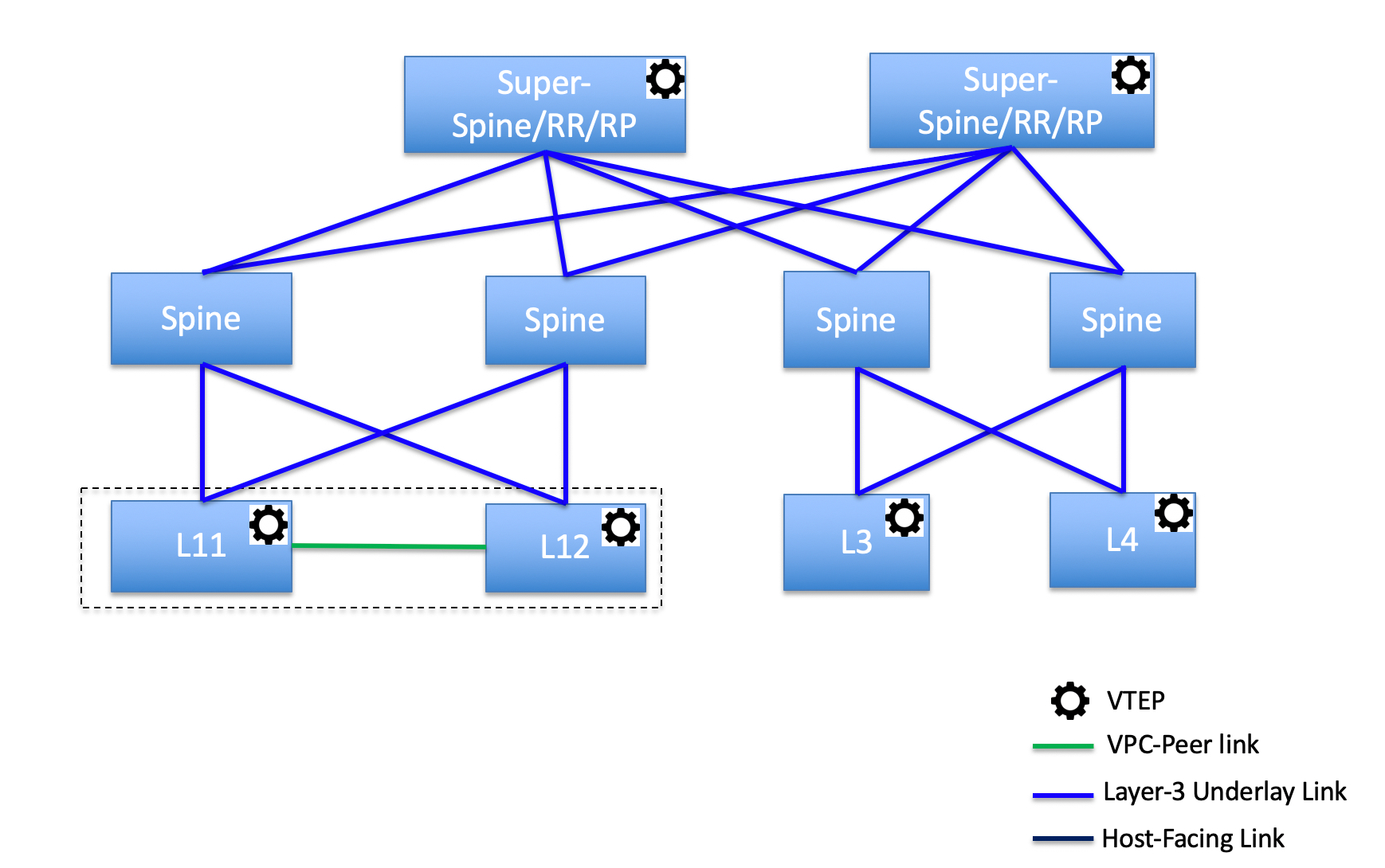
In this topology, leaf switches are connected to spines, and spines are connected to super spine switches which can be super spines, border super spines, and border gateway super spines.

Topology 2: Super Spine Switches Connected to Border

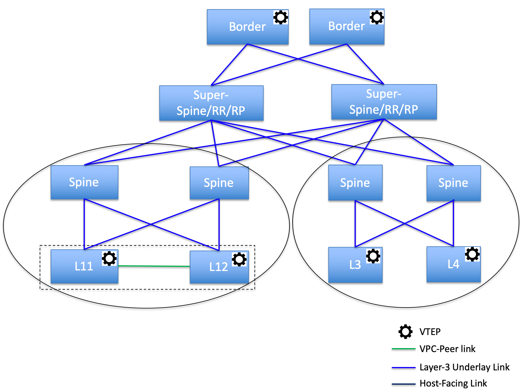
In this topology, there are four leaf switches connecting to the spine switches, which are connected to two super spine switches. These super spine switches are connected to the border or border gateway leaf switches.

Adding a Super Spine Switch to an Existing VXLAN BGP EVPN Fabric

To add a super spine switch to an existing VXLAN BGP EVPN fabric, perform the following steps:

Procedure

Step 1

Choose LAN > Fabrics. Double-click on the required fabric.

The Fabric Overview window appears.

Step 2

On the Switches tab, click Actions > Add Switches.

For more information, see Adding Switches to a Fabric.

Step 3

Right-click on an existing switch or the newly added switch, and use the Set role option to set the appropriate super spine role.

Note

 
  • If the Super Spine role exists in the fabric, you can assign border super spine and border gateway super spine roles for any new device.

  • If super spine or any of its variation role is not assigned, you may assign the role to any new device if it is connected to a non-border spine. After a Recalculate & Deploy, you will receive an error that can be resolved by clicking on the Resolve button as shown in the below steps.

Step 4

On the Fabric Overview window, click Actions > Recalculate & Deploy.

The following error message is displayed:

Super Spine role cannot be allowed in the existing fabric as it is disruptive. Please go to 'Event Analytics' and click on the resolve button to proceed.

Step 5

Choose Event Analytics > Alarms, click on the ID.

The Alarm ID slide-in pane appears.

Step 6

Click Resolve.

The Confirm action dialog box appears.

Step 7

Click Confirm.

Step 8

On the Fabric Overview window, click Actions > Recalculate & Deploy.

Do not add a devices with super spine, border super spine, or border gateway super spine role if the device is connected to a border spine or border gateway spine. This action results in an error after you recalculate and deploy the configuration. To use existing devices with border spine roles, remove the device and add the device with appropriate roles.


Overlay Mode

You can create a VRF or network in CLI or config-profile mode at the fabric level. The overlay mode of member fabrics of an MSD fabric is set individually at the member-fabric level. Overlay mode can only be changed before deploying overlay configurations to the switches. After the overlay configuration is deployed, you cannot change the mode unless all the VRF and network attachments are removed.


Note


If you upgrade from Cisco DCNM Release 11.5(x), the existing config-profile mode functions the same.


If the switch has config-profile based overlays, you can import it in the config-profile overlay mode only. If you import it in the cli overlay mode, an error appears during brownfield import.

For brownfield import, if overlay is deployed as config-profile mode, it can be imported in config-profile mode only. However, if overlay is deployed as cli, it can be imported in either config-profile or cli modes.

To choose the overlay mode of VRFs or networks in a fabric, perform the following steps:

  1. Navigate to the Edit Fabric window.

  2. Go to the Advanced tab.

  3. From the Overlay Mode drop-down list, choose config-profile or cli.

    The default mode is config-profile.

Sync up Out-of-Band Switch Interface Configurations

Any interface level configuration made outside of Nexus Dashboard Fabric Controller (via CLI) can be synced to Nexus Dashboard Fabric Controller and then managed from Nexus Dashboard Fabric Controller. Also, the vPC pair configurations are automatically detected and paired. This applies to the External_Fabric and Classic LAN fabrics only. The vPC pairing is performed with the vpc_pair policy.


Note


When Nexus Dashboard Fabric Controller is managing switches, ensure that all configuration changes are initiated from Nexus Dashboard Fabric Controller and avoid making changes directly on the switch.


When the interface config is synced up to the Nexus Dashboard Fabric Controller intent, the switch configs are considered as the reference, that is, at the end of the sync up, the Nexus Dashboard Fabric Controller intent reflects what is present on the switch. If there were any undeployed intent on Nexus Dashboard Fabric Controller for those interfaces before the resync operation, they will be lost.

Guidelines

  • Supported in fabrics using the following templates: Data Center VXLAN EVPN, External_Fabric, and Classic LAN.

  • Supported for Cisco Nexus switches only.

  • Supported for interfaces that don’t have any fabric underlay related policy associated with them prior to the resync. For example, IFC interfaces and intra fabric links aren’t subjected to resync.

  • The time taken by host port resync depends on the number of switches/interfaces to be synchronized.

  • Supported for interfaces that do not have any custom policy (policy template that isn’t shipped with Cisco Nexus Dashboard Fabric Controller) associated with them prior to resync.

  • Supported for interfaces where the intent is not exclusively owned by a Cisco Nexus Dashboard Fabric Controller feature and/or application prior to resync.

  • Supported on switches that don’t have Interface Groups associated with them.

  • Interface mode (switchport to routed, trunk to access, and so on) changes aren’t supported with overlays attached to that interface.

The sync up functionality is supported for the following interface modes and policies:

Interface Mode Policies
trunk (standalone, po, and vPC PO)
  • int_trunk_host

  • int_port_channel_trunk_host

  • int_vpc_trunk_host

access (standalone, po, and vPC PO)
  • int_access_host

  • int_port_channel_access_host

  • int_vpc_access_host

dot1q-tunnel
  • int_dot1q_tunnel_host

  • int_port_channel_dot1q_tunnel_host

  • int_vpc_ dot1q_tunnel_host

routed

int_routed_host

loopback

int_freeform

sub-interface

int_subif

FEX (ST, AA)
  • int_port_channel_fex

  • int_port_channel_aa_fex

breakout

interface_breakout

nve int_freeform (only in External_Fabric/Classic LAN)
SVI int_freeform (only in External_Fabric/Classic LAN)
mgmt0 int_mgmt

In an Easy fabric, the interface resync will automatically update the network overlay attachments based on the access VLAN or allowed VLANs on the interface.

After the resync operation is completed, the switch interface intent can be managed using normal Nexus Dashboard Fabric Controller procedures.

Syncing up Switch Interface Configurations

It is recommended to deploy all switch configurations from NDFC. In some scenarios, it may be necessary to make changes to the switch interface configuration out-of-band. This will cause configuration drift causing switches to be reported Out-of-Sync.

NDFC supports syncing up the out-of-band interface configuration changes back into its intent.

Guidelines and Limitations

The following limitations are applicable after Syncing up Switch Interface Configurations to NDFC:

  • The port channel membership changes (once the policy exists) is not supported.

  • Changing the interface mode (trunk to access etc.) that have overlays attached is not supported.

  • Resync for interfaces that belong to Interface Groups are not supported.

  • The vPC pairing in External_Fabric and Classic LAN templates must be updated with the vpc_pair policy.

  • This feature is supported for easy fabric, external fabric and LAN classic fabric.

  • The resync can be performed for a set of switches and repeated as desired.

  • The time taken by host port resync depends on the number of switches/interfaces to be synchronized.

  • In Data Center VXLAN EVPN fabrics, VXLAN overlay interface attachments are performed automatically based on the allowed VLANs.

Before you begin
  • We recommend taking a fabric backup before attempting the interface resync.

  • In External_Fabric and Classic LAN fabrics, for the vPC pairing to work correctly, both the switches must be in the fabric and must be functional.

  • Ensure that the switches are In-Sync and switch mode must not be Migration or Maintenance.

  • From the Actions drop-list, choose Discovery > Rediscover to ensure that NDFC is aware of any new interfaces and other changes.

Procedure

Step 1

Choose LAN > Fabrics and double-click on a fabric.

The Fabric Overview window appears.

Step 2

Click the Switches tab and ensure that switches are present in the fabric and vPC pairings are completed.

Step 3

Click the Policies tab and select one or more switches where the interface intent resync is needed.

Note

 
  • If a pair of switches is already paired with either no_policy or vpc_pair, select only one switch of the pair.

  • If a pair of switches is not paired, then select both the switches.

Step 4

From the Actions drop-down list, choose Add Policy.

The Create Policy window appears.

Step 5

On the Create Policy window, choose host_port_resync from the Policy drop-down list.

Step 6

Click Save.

Step 7

Check the Mode column for the switches to ensure that they report Migration. For a vPC pair, both switches are in the Migration-mode.

  • After this step, the switches in the Topology view are in Migration-mode.

  • Both the switches in a vPC pair are in the migration mode even if one of the switches is placed into this mode.

  • If switch(es) are unintentionally put into the resync mode, they can be moved back to the normal mode by identifying the host_port_resync policy instance and deleting it from the Policies tab.

Step 8

After the configuration changes are ready to sync up to NDFC, navigate to the Switches tab and select the required switches.

Step 9

Click Recalculate & Deploy to start the resync process.

Note


This process might take some time to complete based on the size of the switch configuration and the number of switches involved.

The time taken by host port resync depends on the number of switches/interfaces to be synchronized.

Step 10

The Deploy Configuration window is displayed if no errors are detected during the resync operation. The interface intent is updated in NDFC.

Note


If the External_Fabric or Classic LAN fabric is in Monitored Mode, an error message indicating that the fabric is in the read-only mode is displayed. This error message can be ignored and doesn’t mean that the resync process has failed.

Close the Deploy Configuration window, and you can see that the switches are automatically moved out of the Migration-mode. Switches in a vPC pair that were not paired or paired with no_policy show up as paired and associated with the vpc_pair policy.

Note


The host_port_resync policy that was created for the switch is automatically deleted after the resync process is completed successfully.


Configuration Compliance

The entire intent or expected configuration defined for a given switch is stored in NDFC. When you want to push this configuration down to one or more switches, the configuration compliance (CC) module is triggered. CC takes the current intent, the current running configuration, and then comes up with the set of configurations that are required to go from the current running configuration to the current expected configuration so that everything will be In-Sync.

When performing a software or firmware upgrade on the switches, the current running configuration on the switches is not changed. Post upgrade, if CC finds that the current running configuration does not have the current expected configuration or intent, it reports an Out-of-Sync status. There is no auto deployment of any configurations. You can preview the diffs that will get deployed to get one or more devices back In-Sync.

With CC, the sync is always from the NDFC to the switches. There is no reverse sync. So, if you make a change out-of-band on the switches that conflicts with the defined intent in NDFC, CC captures this diff, and indicates that the device is Out-of-Sync. The pending diffs will undo the configurations done out-of-band to bring back the device In-Sync. Note that such conflicts due to out-of-band changes are captured by the periodic CC run that occurs every 60 minutes by default, or when you click the RESYNC option either on a per fabric or per switch basis. From Cisco NDFC Release 12.1.1e, the periodic CC runs every 24 hours. You can configure the custom interval with the range of 30-3600 minutes. This configuration can be done by navigating to Server > Server Settings > LAN-Fabric. Note that you can also capture the out-of-band changes for the entire switch by using the CC REST API. For more information, see Cisco NDFC REST API Guide.

To improve ease of use and readability of deployed configurations, CC in NDFC has been enhanced with the following:

  • All displayed configurations in NDFC are easily readable and understandable.

  • Repeated configuration snippets are not displayed.

  • Pending configurations precisely show only the diff configuration.

  • Side-by-side diffs has greater readability, integrated search or copy, and diff summary functions.

Top-level configuration commands on the switch that do not have any associated NDFC intent are not checked for compliance by CC. However, CC performs compliance checks, and attempts removal, of the following commands even if there is no NDFC intent:

  • configure profile

  • apply profile

  • interface vlan

  • interface loopback

  • interface Portchannel

  • Sub-interfaces, for example, interface Ethernet X/Y.Z

  • fex

  • vlan <vlan-ids>

CC performs compliance checks, and attempts removal, of these commands only when Data Center VXLAN EVPN and BGP Fabric templates are used. On External_Fabric and Classic LAN templates, top-level configuration commands on the switch, including the commands mentioned above, that do not have any associated NDFC intent are not checked for compliance by CC.

We recommend using the NDFC freeform configuration template to create additional intent and deploy these commands to the switches to avoid unexpected behavior

Now, consider a scenario in which the configuration that exists on the switch has no relationship with the configuration defined in the intent. Examples of such configurations are a new feature that has not been captured in the intent but is present on the switch or some other configuration aspect that has not been captured in the intent. Configuration compliance does not consider these configuration mismatches as a diff. In such cases, Strict Configuration Compliance ensures that every configuration line that is defined in the intent is the only configuration that exists on the switch. However, configuration such as boot string, rommon configuration, and other default configurations are ignored during strict CC checks. For such cases, the internal configuration compliance engine ensures that these config changes are not called out as diffs. These diffs are also not displayed in the Pending Config window. But, the Side-by-side diff utility compares the diff in the two text files and does not leverage the internal logic used in the diff computation. As a result, the diff in default configurations are highlighted in red in the Side-by-side Comparison window.

In NDFC, the diffs in default configurations are not highlighted in the Side-by-side Comparison window. The auto-generated default configuration that is highlighted in the Running config window is not visible in the Expected config window.

Any configurations that are shown in the Pending Config window are highlighted in red in the Side-by-side Comparison window if the configurations are seen in the Running config window but not in the Expected config window. Also, any configurations that are shown in the Pending Config window are highlighted in green in the Side-by-side Comparison window if the configurations are seen in the Expected config window but not in the Running config window. If there are no configurations displayed in the Pending Config window, no configurations are shown in red in the Side-by-side Comparison window.

All freeform configurations have to strictly match the show running configuration output on the switch and any deviations from the configuration will show up as a diff during Recalculate & Deploy. You need to adhere to the leading space indentations.

You can typically enter configuration snippets in NDFC using the following methods:

  • User-defined profile and templates

  • Switch, interface, overlay, and vPC freeform configurations

  • Network and VRF per switch freeform configurations

  • Fabric settings for Leaf, Spine, or iBGP configurations


Caution


The configuration format should be identical to the show running configuration of the corresponding switch. Otherwise, any missing or incorrect leading spaces in the configuration can cause unexpected deployment errors and unpredictable pending configurations. If any unexpected diffs or deployment errors are displayed, check the user-provided or custom configuration snippets for incorrect values.


If NDFC displays the "Out-of-Sync" status due to unexpected pending configurations, and this configuration is either unable to be deployed or stays consistent even after a deployment, perform the following steps to recover:

  1. Check the lines of config highlighted under the Pending Config tab in the Config Preview window.

  2. Check the same lines in the corresponding Side-by-side Comparison tab. This tab shows whether the diff exists in "intent", or "show run", or in both with different leading spaces. Leading spaces are highlighted in the Side-by-side Comparison tab.

  3. If the pending configurations or switch with an out-of-sync status is due to any identifiable configuration with mismatched leading spaces in "intent" and "running configuration", this indicates that the intent has incorrect spacing and needs to be edited.

  4. To edit incorrect spacing on any custom or user-defined policies, navigate to the switch and edit the corresponding policy:

    1. If the source of the policy is UNDERLAY, you will need to edit this from the Fabric settings screen and save the updated configuration.

    2. If the source is blank, it can be edited from the View/Edit policies window for that switch.

    3. If the source of the policy is OVERLAY, but it is derived from a switch freeform configuration. In this case, navigate to the appropriate OVERLAY switch freeform configuration and update it.

    4. If the source of the policy is OVERLAY or a custom template, perform the following steps:

      1. Choose Settings > Server settings, set the template.in_use.check property to false and uncheck the Template In-Use Override check box and Save. This allows the profiles or templates to be editable.

      2. Edit the specific profile or template from the Operations > Templates > Edit template properties edit window, and save the updated profile template with the right spacing.

      3. Click Recalculate & Deploy to recompute the diffs for the impacted switches.

      4. After the configurations are updated, set the template.in_use.check property to true and check the Template In-Use Override check box and Save, as it slows down the performance of the NDFC system, specifically for Recalculate & Deploy operations.

If NDFC displays "NA" in the Config Status, the following guidelines apply:

  • It is expected when the switch 'Mode' is 'Migration'. This could be due to some of the NDFC work flows. Follow the associated work flow steps to get the switch mode to the 'Normal' state and associated Config Status.

  • In all other cases, it may indicate a transient state where NDFC was not able to compute the correct 'Config Status'. Do the following:

    • If seen on one switch, then perform switch level Preview or Deploy.

    • If seen on multiple switches, then select those switches and perform Preview or Deploy.

    • If seen at a fabric level, then select all switches and perform Preview or Deploy.

    • R&D is also an option for fabric level but this does a Config Save operation as well which could take time in a large fabric.

To confirm that the diffs have been resolved, click Recalculate & Deploy after updating the policy to validate the changes.


Note


NDFC checks only leading spaces, as it implies hierarchy of the command, especially in case of multi-command sequences. NDFC does not check any trailing spaces in command sequences.


Example 1: Configuration Compliance in Switch Freeform Policy

Let us consider an example with an incorrect spacing in the Switch Freeform Configuration field.

Create the switch freeform policy.

After deploying this policy successfully to the switch, NDFC persistently reports the diffs.

After clicking the Side-by-side Comparison tab, you can see the cause of the diff. The ip pim rp-address line has 2 leading spaces, while the running configuration has 0 leading spaces.

To resolve this diff, edit the corresponding Switch Freeform policy so that the spacing is correct.

After you save, you can use the Push Config or Recalculate & Deploy option to re-compute diffs.

The diffs are now resolved. The Side-by-side Comparison tab confirms that the leading spaces are updated.

Example 2: Resolving a Leading Space Error in Overlay Configurations

Let us consider an example with a leading space error that is displayed in the Pending Config tab.

In the Side-by-side Comparison tab, search for diffs line by line to understand context of the deployed configuration.

A matched count of 0 means that it is a special configuration that NDFC has evaluated to push it to the switch.

You can see that the leading spaces are mismatched between running and expected configurations.

Navigate to the respective freeform configs and correct the leading spaces, and save the updated configuration.

Navigate to Fabric Overview window for the fabric and click Recalculate & Deploy.

In the Deply Configuration window, you can see that all the devices are in-sync.

Configuration Compliance in External Fabrics

With external fabrics, any Nexus switches, Cisco IOS-XE devices, Cisco IOS XR devices, and Arista can be imported into the fabric, and there is no restriction on the type of deployment. It can be LAN Classic, VXLAN, FabricPath, vPC, HSRP, etc. When switches are imported into an external fabric, the configuration on the switches is retained so that it is non-disruptive. Only basic policies such as the switch username and mgmt0 interface are created after a switch import.

In the external fabric, for any intent that is defined in the Nexus Dashboard Fabric Controller, configuration compliance (CC) ensures that this intent is present on the corresponding switch. If this intent is not present on the switch, CC reports an Out-of-Sync status. Additionally, there will be a Pending Config generated to push this intent to the switch to change the status to In-Sync. Any additional configuration that is on the switch but not in intent defined in Nexus Dashboard Fabric Controller, will be ignored by CC, as long as there is no conflict with anything in the intent.

When there is user-defined intent added on Nexus Dashboard Fabric Controller and the switch has additional configuration under the same top-level command, as mentioned earlier, CC will only ensure that the intent defined in Nexus Dashboard Fabric Controller is present on the switch. When this user defined intent on Nexus Dashboard Fabric Controller is deleted as a whole with the intention of removing it from the switch and the corresponding configuration exists on the switch, CC will report an Out-of-Sync status for the switch and will generate Pending Config to remove the config from the switch. This Pending Config includes the removal of the top-level command. This action leads to removal of the other out-of-band configurations made on the switch under this top-level command as well. If you choose to override this behavior, the recommendation is that, you create a freeform policy and add the relevant top-level command to the freeform policy.

Let us see this behavior with an example.

  1. A switch_freeform policy defined by the user in Nexus Dashboard Fabric Controller and deployed to the switch.

  2. Additional configuration exists under router bgp in Running config that does not exist in user-defined Nexus Dashboard Fabric Controller intent Expected config. Note that there is no Pending Config to remove the additional config that exists on the switch without a user defined intent on Nexus Dashboard Fabric Controller.

  3. The Pending Config and the Side-by-side Comparison when the intent that was pushed earlier via Nexus Dashboard Fabric Controller is deleted from Nexus Dashboard Fabric Controller by deleting the switch_freeform policy that was created in the Step 1.

  4. A switch_freeform policy with the top-level router bgp command needs to be created. This enables CC to generate the configuration needed to remove only the desired sub-config which was pushed from Nexus Dashboard Fabric Controller earlier.

  5. The removed configuration is only the subset of the configuration that was pushed earlier from Nexus Dashboard Fabric Controller.

    For interfaces on the switch in the external fabric, Nexus Dashboard Fabric Controller either manages the entire interface or does not manage it at all. CC checks interfaces in the following ways:

    • For any interface, if there is a policy defined and associated with it, then this interface is considered as managed. All configurations associated with this interface must be defined in the associated interface policy. This is applicable for both logical and physical interfaces. Otherwise, CC removes any out-of-band updates made to the interface to change the status to In-Sync.

    • Interfaces created out-of-band (applies for logical interfaces such as port-channels, sub interfaces, SVIs, loopbacks, etc.), will be discovered by Nexus Dashboard Fabric Controller as part of the regular discovery process. However, since there is no intent for these interfaces, CC will not report an Out-of-Sync status for these interfaces.

    • For any interface, there can always be a monitor policy associated with it in Nexus Dashboard Fabric Controller. In this case, CC will ignore the interface’s configuration when it reports the In-Sync or Out-of-Sync config compliance status.

Special Configuration CLIs Ignored for Configuration Compliance

The following configuration CLIs are ignored during configuration compliance checks:

  • Any CLI having 'username’ along with ‘password’

  • Any CLI that starts with ‘snmp-server user’

Any CLIs that match the above will not show up in pending diffs and clicking Save & Deploy in the Fabric Builder window will not push such configurations to the switch. These CLIs will not show up in the Side-by-side Comparison window also.

To deploy such configuration CLIs, perform the following procedure:

Procedure

Step 1

Select LAN > Fabrics.

Double click on the fabric name to view Fabric Overview screen.

Step 2

On the Switches tab, double click on the switch name to view Switch Overview screen.

On the Policies tab, all the policies applied on the switch within the chosen fabric are listed.

Step 3

On the Policies tab, from the Actions drop-down list, select Add Policy.

Step 4

Add a Policy Template Instances (PTIs) with the required configuration CLIs using the switch_freeform template and click Save.

Step 5

Select the created policy and select Push Config from the Actions drop-down list to deploy the configuration to the switch(es).


Resolving Diffs for Case Insensitive Commands

By default, all diffs generated in NDFC while comparing intent, also known as Expected Configuration, and Running Configuration, are case sensitive. However, the switch has many commands that are case insensitive, and therefore it may not be appropriate to flag these commands as differences. These are captured in the compliance_case_insensitive_clis.txt template that can be found under Operations > Templates.

From Cisco NDFC Release 12.0.1a, compliance_case_insensitive_clis.txt file, along with compliance_strict_cc_exclude_clis.txt and compliance_ipv6_clis.txt files are now part of the shipped templates. You can find all the templates under Operations > Templates. Modification of templates can be done after disabling Template In-Use Override.

There could be additional commands not included in the existing compliance_case_insensitive_clis.txt file that should be treated as case insensitive. If the pending configuration is due to the differences of cases between the Expected Configuration in NDFC and the Running Configuration, you can configure NDFC to ignore these case differences as follows:

  1. Navigate to Settings > Server Settings > LAN-Fabric, uncheck Template In-Use Override and then click Save.

  2. Navigate to Operations > Templates and search for compliance_case_insensitive_clis.txt file.

  3. Check compliance_case_insensitive_clis.txt and choose Actions > Edit template content.

    An example of the entries in the compliance_case_insensitive_clis.txt file is displayed in the following figure.

  4. Remove the entries highlighted in the figure and click Finish.

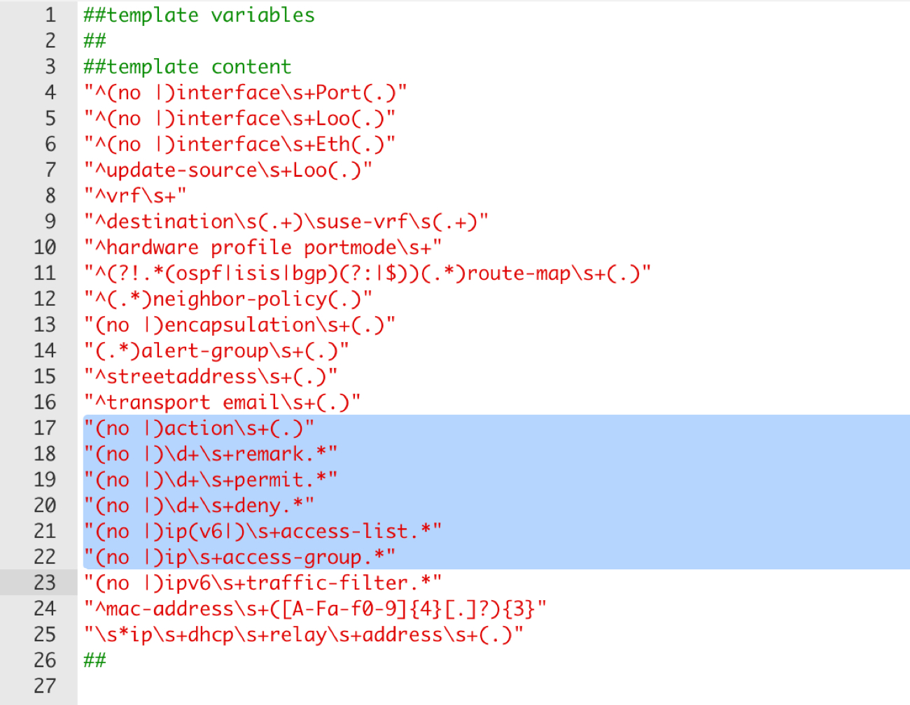
  5. If newer patterns are detected during deployment, and they are triggering pending configurations, you can add these patterns to this file. The patterns need to be valid regex patterns.

  6. Navigate to Settings > Server Settings > LAN-Fabric, check Template In-Use Override and then click Save.

    This enables NDFC to treat the documented configuration patterns as case insensitive while performing comparisons.

  7. Click Recalculate & Deploy for fabrics to view the updated comparison outputs.

Resolving Configuration Compliance After Importing Switches

After importing switches in Cisco NDFC, configuration compliance for a switch can fail because of an extra space in the management interface (mgmt0) description field.

For example, before importing the switch:


interface mgmt0
  description SRC=SDS-LB-LF111-mgmt0, DST=SDS-LB-SW001-Fa0/5

After importing the switch and creating a configuration profile:


interface mgmt0
  description SRC=SDS-LB-LF111-mgmt0,DST=SDS-LB-SW001-Fa0/5

Navigate to Interface Manager and click the Edit icon after selecting the mgmt0 interface. Remove the extra space in the description.

Strict Configuration Compliance

Strict configuration compliance checks for diff between the switch configuration and the associated intent and generates no commands for the configurations that present on the switch but are not present in the associated intent. When you click Recalculate and Deploy, switch configurations that are not present on the associated intent are removed. You can enable this feature by choosing the Enable Strict Config Compliance check box under the Advanced tab in the Create Fabric or Edit Fabric window. By default, this feature is disabled.

The strict configuration compliance feature is supported on the Easy Fabric templates - Data Center VXLAN EVPN and BGP Fabric. To avoid generating diff for commands that are auto-generated by the switch, such as vdc, rmon, and so on, a file that has a list of default commands is used by CC to ensure that diffs are not generated for these commands. This file is maintained in Operations > Templates, compliance_strict_cc_exclude_clis.txt template.

Example: Strict Configuration Compliance

Let us consider an example in which the feature telnet command is configured on a switch but is not present in the intent. In such a scenario, the status of the switch is displayed as Out-of-sync after a CC check is done.

Now, click Preview Config of the out-of-sync switch. As the strict configuration compliance feature is enabled, the no form of the feature telnet command appears under Pending Config in the Preview Config window.

Click the Side-by-side Comparison tab to display the differences between the running configuration and the expected configuration. The Re-sync button is also displayed at the top right corner under the Side-by-side Comparison tab in the Preview Config window. Use this option to resynchronize NDFC state when there is a large scale out-of-band change, or if configuration changes do not register in the NDFC properly.

The re-sync operation does a full CC run for the switch and recollects “show run” and “show run all” commands from the switch. When you initiate the re-sync process, a progress message is displayed. During the re-sync, the running configuration is taken from the switch. The Out-of- Sync/In-Sync status for the switch is recalculated based on the intent defined in NDFC.

Now, close the Preview Config window and click Recalculate and Deploy. The strict configuration compliance feature ensures that the running configuration on the switch does not deviate from the intent by pushing the no form of the feature telnet command to the switch. The diff between the configurations is highlighted. The diff other than the feature telnet command are default switch and boot configurations and are ignored by the strict CC check.

You can right-click on a switch in the Fabric Overview window and select Preview Config to display the Preview Config window. This window displays the pending configuration that has to be pushed to the switch to achieve configuration compliance with the intent.

Custom freeform configurations can be added in NDFC to make the intended configuration on NDFC and the switch configurations identical. The switches are then in In-Sync status. For more information on how to add custom freeform configurations on NDFC, refer Enabling Freeform Configurations on Fabric Switches.

Enabling Freeform Configurations on Fabric Switches

In Nexus Dashboard Fabric Controller, you can add custom configurations through freeform policies in the following ways:

  1. Fabric-wide:

    • On all leaf, border leaf, and border gateway leaf switches in the fabric, at once.

    • On all spine, super spine, border spine, border super spine, border gateway spine and border switches, at once.

  2. On a specific switch at the global level.

  3. On a specific switch on a per Network or per VRF level.

  4. On a specific interface on a switch.

Leaf switches are identified by the roles Leaf, Border, and Border Gateway. The spine switches are identified by the roles Spine, Border Spine, Border Gateway Spine, Super Spine, Border Super Spine, and Border Gateway Super Spine.


Note


You can deploy freeform CLIs when you create a fabric or when a fabric is already created. The following examples are for an existing fabric. However, you can use this as a reference for a new fabric.


Deploying Fabric-Wide Freeform CLIs on Leaf and Spine Switches

  1. Choose LAN > Fabrics > Fabrics.

  2. Select the Fabric, and select Edit Fabric from Actions drop-down list.

    (If you are creating a fabric for the first time, click Create Fabric).

  3. Click the Advanced tab and update the following fields:

    Leaf Freeform Config – In this field, add configurations for all leaf, border leaf, and border gateway leaf switches in the fabric.

    Spine Freeform Config - In this field, add configurations for all Spine, Border Spine, Border Gateway Spine, Super Spine, Border Super Spine, and Border Gateway Super Spine switches in the fabric.


    Note


    Copy-paste the intended configuration with correct indentation, as seen in the running configuration on the Nexus switches. For more information, see Resolving Freeform Config Errors in Switches.


  4. Click Save. The fabric topology screen comes up.

  5. Click Deploy Config from the Actions drop-down list to save and deploy configurations.

    Configuration Compliance functionality ensures that the intended configuration as expressed by those CLIs are present on the switches and if they are removed or there is a mismatch, then it flags it as a mismatch and indicate that the device is Out-of-Sync.

Incomplete Configuration Compliance - On some Cisco Nexus 9000 Series switches, in spite of configuring pending switch configurations using the Deploy Config option, there could be a mismatch between the intended and switch configuration. To resolve the issue, add a switch_freeform policy to the affected switch (as explained in the Deploy Freeform CLIs on a Specific Switch section). For example, consider the following persistent pending configurations:


line vty
logout-warning 0

After adding the above configurations in a policy and saving the updates, click Deploy Config in the topology screen to complete the deployment process.

To bring back the switch in-sync, you can add the above configuration in a switch_freeform policy saved and deployed onto the switch.

Deploying Freeform CLIs on a Specific Switch

  1. Choose LAN > Fabrics > Fabrics.

  2. Select the Fabric, and select Edit Fabric from Actions drop-down list.

  3. Click Policies tab. From the Actions drop-down list, choose Add Policy.

    The Create Policy screen comes up.


    Note


    To provision freeform CLIs on a new fabric, you have to create a fabric, import switches into it, and then deploy freeform CLIs.


  4. In the Priority field, the priority is set to 500 by default. You can choose a higher priority (by specifying a lower number) for CLIs that need to appear higher up during deployment. For example, a command to enable a feature should appear earlier in the list of commands.

  5. In the Description field, provide a description for the policy.

  6. From the Template Name field, select freeform_policy.

  7. Add or update the CLIs in the Freeform Config CLI box.

    Copy-paste the intended configuration with correct indentation, as seen in the running configuration on the Nexus switches. For more information, see Resolving Freeform Config Errors in Switches.

  8. Click Save.

    After the policy is saved, it gets added to the intended configurations for that switch.

  9. From the Fabric Overview window, click the Switches tab and choose the required switches.

  10. On the Switches tab, click Actions drop-down list and choose Deploy.

Pointers for freeform_policy Policy Configuration:

  • You can create multiple instances of the policy.

  • For a vPC switch pair, create consistent freeform_policy policies on both the vPC switches.

  • When you edit a freeform_policy policy and deploy it onto the switch, you can see the changes being made (in the Side-by-side tab of the Preview option).

Freeform CLI Configuration Examples

Console line configuration

This example involves deploying some fabric-wide freeform configurations (for all leaf, and spine switches), and individual switch configurations.

Fabric-wide session timeout configuration:


line console
  exec-timeout 1

Console speed configuration on a specific switch:


line console
  speed 115200

IP Prefix List/Route-map configuration

IP prefix list and route-map configurations are typically configured on border devices. These configurations are global because they can be defined once on a switch and then applied to multiple VRFs as needed. The intent for this configuration can be captured and saved in a switch_freeform policy. As mentioned earlier, note that the configuration saved in the policy should match the show run output. This is especially relevant for prefix lists where the NX-OS switch may generate sequence numbers automatically when configured on the CLI. An example snippet is shown below:

ip prefix-list prefix-list-name1 seq 5 permit 20.2.0.1/32
ip prefix-list prefix-list-name1 seq 6 permit 20.2.0.2/32
ip prefix-list prefix-list-name2 seq 5 permit 192.168.100.0/24

ACL configuration

ACL configurations are typically configured on specific switches and not fabric-wide (leaf/spine switches). When you configure ACLs as freeform CLIs on a switch, you should include sequence numbers. Else, there will be a mismatch between the intended and running configuration. A configuration sample with sequence numbers:

ip access-list ACL_VTY 
  10 deny tcp 172.29.171.67/32 172.29.171.36/32 
  20 permit ip any any 
ip access-list vlan65-acl 
  10 permit ip 69.1.1.201/32 65.1.1.11/32 
  20 deny ip any any 

interface Vlan65
  ip access-group vlan65-acl in 
line vty
  access-class ACL_VTY in

If you have configured ACLs without sequence numbers in a freeform_policy policy, update the policy with sequence numbers as shown in the running configuration of the switch.

After the policy is updated and saved, right click the device and select the per switch Deploy Config option to deploy the configuration.

Resolving Freeform Config Errors in Switches

Copy-paste the running-config to the freeform config with correct indentation, as seen in the running configuration on the NX-OS switches. The freeform config must match the running config. Otherwise, configuration compliance in Nexus Dashboard Fabric Controller marks switches as out-of-sync.

Let us see an example of the freeform config of a switch.

feature bash-shell
feature telemetry
 
clock timezone CET 1 0
# Daylight saving time is observed in Metropolitan France from the last Sunday in March (02:00 CET) to the last Sunday in October (03:00 CEST)
clock summer-time CEST 5 Sunday March 02:00 5 Sunday October 03:00 60
clock protocol ntp
 
telemetry
  destination-profile
    use-vrf management

The highlighted line about the daylight saving time is a comment that is not displayed in the show running config command output. Therefore, configuration compliance marks the switch as out-of-sync because the intent does not match the running configuration.

Let us check the running config in the switch for the clock protocol.

spine1# show run all | grep "clock protocol"
clock protocol ntp vdc 1

You can see that vdc 1 is missing from the freeform config.

In this example, let us copy-paste the running config to the freeform config.

Here is the updated freeform config:

feature bash-shell
feature telemetry
 
clock timezone CET 1 0
clock summer-time CEST 5 Sunday March 02:00 5 Sunday October 03:00 60
clock protocol ntp vdc 1
 
telemetry
  destination-profile
    use-vrf management

After you copy-paste the running config and deploy, the switch will be in-sync. When you click Recalculate Config, click the Pending Config column. The Side-by-Side Comparison to view information about the difference between the defined intent and the running config.

Deploying Freeform CLIs on a Specific Switch on a Per VRF/Network basis

  1. Choose LAN > Fabrics > Fabrics.

  2. Select the Fabric, and select Edit Fabric from Actions drop-down list.

  3. Click VRFs tab. From the Actions drop-down list, select Create.

    The Create VRF screen comes up.

  4. Select an individual switch. The VRF attachment form shows up listing the switch that is selected. In case of a vPC pair, both switches belonging to the pair shows up.

  5. Under the CLI Freeform column, select the button labeled Freeform config. This option allows a user to specify additional configuration that should be deployed to the switch along with the VRF profile configuration.

  6. Add or update the CLIs in the Free Form Config CLI box. Copy-paste the intended configuration with correct indentation, as seen in the running configuration on the Nexus switches. For more information, see Resolving Freeform Config Errors in Switches.

  7. Click Deploy Config.


    Note


    The Freeform config button will be gray when there is no per VRF per switch config specified. The button will be blue when some config has been saved by the user.


    After the policy is saved, Click Save on the VRF Attachment pop-up to save the intent to deploy the VRF to that switch. Ensure that the checkbox on the left next to the switch is checked.

  8. Now, optionally, click Preview to look at the configuration that will be pushed to the switch.

  9. Click Deploy Config to push the configuration to the switch.

The same procedure can be used to define a per Network per Switch configuration.

MACsec Support in Easy Fabric and eBGP Fabric

MACsec is supported in the Easy Fabric and eBGP Fabric on intra-fabric links. You should enable MACsec on the fabric and on each required intra-fabric link to configure MACsec. Unlike CloudSec, auto-configuration of MACsec is not supported.

MACsec is supported on switches with minimum Cisco NX-OS Releases 7.0(3)I7(8) and 9.3(5).

Guidelines

  • If MACsec cannot be configured on the physical interfaces of the link, an error is displayed when you click Save. MACsec cannot be configured on the device and link due to the following reasons:

    • The minimum NX-OS version is not met.

    • The interface is not MACsec capable.

  • MACsec global parameters in the fabric settings can be changed at any time.

  • MACsec and CloudSec can coexist on a BGW device.

  • MACsec status of a link with MACsec enabled is displayed on the Links window.

  • Brownfield migration of devices with MACsec configured is supported using switch and interface freeform configs.

    For more information about MACsec configuration, which includes supported platforms and releases, see the Configuring MACsec chapter in Cisco Nexus 9000 Series NX-OS Security Configuration Guide.

The following sections show how to enable and disable MACsec in Nexus Dashboard Fabric Controller:

Enabling MACsec

Procedure

Step 1

Navigate to LAN > Fabrics.

Step 2

Click Actions > Create to create a new fabric or click Actions > Edit Fabric on an existing Easy or eBGP fabric.

Step 3

Click the Advanced tab and specify the MACsec details.

Enable MACsec – Select the check box to enable MACsec for the fabric.

MACsec Primary Key String – Specify a Cisco Type 7 encrypted octet string that is used for establishing the primary MACsec session. For AES_256_CMAC, the key string length must be 130 and for AES_128_CMAC, the key string length must be 66. If these values are not specified correctly, an error is displayed when you save the fabric.

Note


The default key lifetime is infinite.

MACsec Primary Cryptographic Algorithm – Choose the cryptographic algorithm used for the primary key string. It can be AES_128_CMAC or AES_256_CMAC. The default value is AES_128_CMAC.

You can configure a fallback key on the device to initiate a backup session if the primary session fails.

MACsec Fallback Key String – Specify a Cisco Type 7 encrypted octet string that is used for establishing a fallback MACsec session. For AES_256_CMAC, the key string length must be 130 and for AES_128_CMAC, the key string length must be 66. If these values are not specified correctly, an error is displayed when you save the fabric.

MACsec Fallback Cryptographic Algorithm – Choose the cryptographic algorithm used for the fallback key string. It can be AES_128_CMAC or AES_256_CMAC. The default value is AES_128_CMAC.

MACsec Cipher Suite – Choose one of the following MACsec cipher suites for the MACsec policy:

  • GCM-AES-128

  • GCM-AES-256

  • GCM-AES-XPN-128

  • GCM-AES-XPN-256

The default value is GCM-AES-XPN-256.

Note


The MACsec configuration is not deployed on the switches after the fabric deployment is complete. You need to enable MACsec on intra-fabric links to deploy the MACsec configuration on the switch.

MACsec Status Report Timer – Specifies MACsec operational status periodic report timer in minutes.

Step 4

Click a fabric to view the Summary in the side kick. Click the side kick to expand. Click Links tab.

Step 5

Choose an intra-fabric link on which you want to enable MACsec and click Actions > Edit.

Step 6

In the Link Management – Edit Link window, click Advanced in the Link Profile section, and select the Enable MACsec check box.

If MACsec is enabled on the intra fabric link but not in the fabric settings, an error is displayed when you click Save.

When MACsec is configured on the link, the following configurations are generated:

  • Create MACsec global policies if this is the first link that enables MACsec.

  • Create MACsec interface policies for the link.

Step 7

From the Fabric Actions drop-down list, select Deploy Config to deploy the MACsec configuration.


Disabling MACsec

To disable MACsec on an intra-fabric link, navigate to the Link Management – Edit Link window, unselect the Enable MACsec check box, click Save. From the Fabric Actions drop-down list, select Deploy Config to disable MACsec configuration. This action performs the following:

  • Deletes MACsec interface policies from the link.

  • If this is the last link where MACsec is enabled, MACsec global policies are also deleted from the device.

Only after disabling MACsec on links, navigate to the Fabric Settings and unselect the Enable MACsec check box under the Advanced tab to disable MACsec on the fabric. If there’s an intra-fabric link in the fabric with MACsec enabled, an error is displayed when you click Actions > Recalculate Config from the Fabric Actions drop-down list.

Create Data Center VXLAN EVPN for Cisco Catalyst 9000 Series Switches

You can add Cisco Catalyst 9000 Series Switches to an easy fabric using the Campus VXLAN EVPN fabric template. You can add only Cisco Catalyst 9000 IOS XE switches to this fabric. This fabric supports OSPF as underlay protocol and BGP EVPN as the overlay protocol. Using this fabric template allows Nexus Dashboard Fabric Controller to manage all the configurations of a VXLAN EVPN Fabric composed of Cisco Catalyst 9000 IOS-XE switches. Backing up and restoring this fabric is the same as the Data Center VXLAN EVPN.

Guidelines

  • EVPN VXLAN Distributed Anycast Gateway is supported when each SVI is configured with the same Anycast Gateway MAC.

  • StackWise Virtual switch is supported.

  • Brownfield is not supported.

  • Upgrade from earlier versions is not supported (However, it is a preview feature in 11.5).

  • IPv6 Underlay, VXLAN Multi-site, Anycast RP, and TRM is not supported.

  • ISIS, ingress replication, unnumbered intra-fabric link, 4 bytes BGP ASN, and Zero-Touch Provisioning (ZTP) is not supported.


Note


For information about configuration compliance, see Configuration Compliance in External Fabrics.


Creating Easy Fabric for Cisco Catalyst 9000 Series Switches

UI Navigation: Choose LAN > Fabrics.

Perform the following steps to create an easy fabric for Cisco Catalyst 9000 Series Switches:

  1. Choose Create Fabric from the Actions drop-down list.

  2. Enter a fabric name and click Choose Template.

    The Select Fabric Template dialog appears.

  3. Choose the Campus VXLAN EVPN fabric template and click Select.

  4. Fill in all the required fields and click Save.


    Note


    BGP ASN is the only mandatory field.


Adding Cisco Catalyst 9000 Series Switches to IOS-XE Easy Fabrics

Cisco Catalyst 9000 series switches are discovered using SNMP. Hence, before adding them to the fabric, configuring the Cisco Catalyst 9000 series switches includes configuring SNMP views, groups, and users. For more information, see the Configuring IOS-XE Devices for Discovery section.

For StackWise Virtual switches, configure the StackWise Virtual-related configuration before adding them to the fabric.

UI Navigation

Choose any one of the following navigation paths to add switch(es) in the Add Switches window.

  • Choose LAN > Fabrics. Choose a fabric that uses the Campus VXLAN EVPN fabric template from the list, click Actions, and choose Add Switches.

  • Choose LAN > Fabrics. Choose a fabric that uses the Campus VXLAN EVPN fabric template from the list. Click the Switches tab. Click Actions and choose Add Switches.

  • Choose LAN > Switches. Click Actions and choose Add Switches. Click Choose Fabric, choose the IOS-XE VXLAN fabric, and click Select.

Before you begin

Set the default credentials for the device in the LAN Credentials Management window if the default credentials are not set. To navigate to the LAN Credentials Management window from the Cisco Nexus Dashboard Fabric Controller Web UI, choose Settings > LAN Credentials Management.

Procedure

Step 1

Enter values for the following fields:

Field

Description

Seed IP

Enter the IP address of the switch.

You can import more than one switch by providing the IP address range. For example: 10.10.10.40-60

The switches must be properly cabled and reachable to the Cisco Nexus Dashboard Fabric Controller server and the switch status must be manageable.

Authentication Protocol

Choose the authentication protocol from the drop-down list.

Username

Enter the username of the switch(es).

Password

Enter the password of the switch(es).

Note


You can change the Discover and LAN credentials only after discovering the switch.

Step 2

Click Discover Switches.

The switch details are populated.

Cisco Nexus Dashboard Fabric Controller supports the import of Cisco Catalyst 9500 Switches running in StackWise Virtual. The StackWise Virtual configuration to form a pair of Cisco Catalyst 9500 Switches into a virtual switch has to be in place before the import. For more information on how to configure StackWise Virtual, see the Configuring Cisco StackWise Virtual chapter in the High Availability Configuration Guide (Catalyst 9500 Switches) for the required release.

Step 3

Check the check boxes next to the switches you want to import.

You can import only switches with the manageable status.

Step 4

Click Add Switches.

The switch discovery process is initiated and the discovery status is updated under the Discovery Status column in the Switches tab.

Step 5

(Optional) View the details of the device.

After the discovery of the device, the discovery status changes to ok in green.


What to do next
  1. Set the appropriate role. The supported roles are:

    • Leaf

    • Spine

    • Border

    To set the role, choose a switch and click Actions. Choose Set role. Choose a role and click Select.


    Note


    After discovering the switch(es), Nexus Dashboard Fabric Controller usually assigns Leaf as the default role.


  2. Recalculate the configurations and deploy the configurations to the switches.

Recalculating and Deploying Configurations

To recalculate and deploy the configurations to the switch(es) in the IOS-XE easy fabric, perform the following steps to recalculate configurations:

Before you begin

Set the role of the switch(es) in the IOS-XE easy fabric.

Procedure

Step 1

Click Actions from Fabric Overview.

Step 2

Choose Recalculate Config.

Recalculation of configurations starts on the switch(es).


Creating DCI Links for Cisco Catalyst Switches in IOS-XE Easy Fabrics

You can create VRF-Lite IFC between a Cisco Catalyst 9000 Series Switch with border role in IOS-XE easy fabrics, and another switch in a different fabric. The other switch can be a Nexus switch in External Fabric, LAN Classic fabric, or Easy Fabric. It can also be a Catalyst 9000 switch in External Fabric or IOS-XE Easy Fabric. The link can be created only from IOS-XE Easy Fabric.

For more information, see Links and Templates.


Note


When creating DCI links for IOS-XE Easy Fabric, auto-deploy is supported only if the destination device is a Nexus switch.


To create links for IOS-XE Easy Fabric, perform the following procedure:

  1. Navigate to the Links tab in the fabric overview.

    The list of previously created links is displayed. The list contains intra-fabric links, which are between switches within a fabric, and inter-fabric links, which are between border switches in this fabric and switches in other fabrics.

    The inter-fabric links also support edge router switches in the External Fabric, apart from BGW and Border Leaf/Spine.

  2. Click Actions and choose Create.

    The Create Link window appears. By default, the Intra-Fabric option is chosen as the link type.

  3. From the Link Type drop-down box, choose Inter-Fabric . The fields change correspondingly.

  4. Choose VRF_LITE as the link sub-type, ext_fabric_setup template for VRF_LITE IFC, and IOS-XE fabric as the source fabric.

    Link Template: The link template is populated.

    The templates are autopopulated with corresponding pre-packaged default templates that are based on your selection. The template to use for VRF_LITE IFC is ext_fabric_setup.


    Note


    You can add, edit, or delete only the ext_routed_fabric template. For more information, see Templates.


  5. Choose the IOS-XE fabric as the source fabric from the Source Fabric drop-down list.

  6. Choose a destination fabric from the Destination Fabric drop-down list.

  7. Choose the source device and Ethernet interface that connects to the destination device.

  8. Choose the destination device and Ethernet interface that connects to the source device.

  9. Enter values in other fields accordingly.

  10. Click Save.


Note


Instead of the create action, you can also use the Edit action to create VRF-Lite IFC(s) using the existing inter fabric link(s). Choose the VRF_Lite link subtype. By default, if you select Edit, then the data for the fields Link-Type, Source Fabric, Destination Fabric, Source Device, Destination Device, Source Interface and Destination Interface are auto-populated in the Edit Link window.

Choose VRF_LITE as the link sub-type, ext_fabric_setup template for VRF_LITE IFC, and IOS-XE fabric as the source fabric.

To complete the procedure, repeat step 4 to step 10 mentioned above.


Creating VRFs for Cisco Catalyst 9000 Series Switches in IOS-XE Easy Fabrics

UI Navigation

  • Choose LAN > Fabrics. Click on a fabric to open the Fabric slide-in pane. Click the Launch icon. Choose Fabric Overview > VRFs > VRFs.

  • Choose LAN > Fabrics. Double-click on a fabric to open Fabric Overview > VRFs > VRFs.

You can create VRFs for IOS-XE easy fabrics.

To create VRF from the Cisco Nexus Dashboard Fabric Controller Web UI, perform the following steps:

  1. Click Actions and choose Create.

    The Create VRF window appears.

  2. Enter the required details in the mandatory fields. Some of the fields have default values.

    The fields in this window are:

    VRF Name - Specifies a VRF name automatically or allows you to enter a name for Virtual Routing and Forwarding (VRF). The VRF name should not contain any white spaces or special characters except underscore (_), hyphen (-), and colon (:).

    VRF ID - Specifies the ID for the VRF or allows you to enter an ID for the VRF.

    VLAN ID - Specifies the corresponding tenant VLAN ID for the network or allows you to enter an ID for the VLAN. If you want to propose a new VLAN for the network, click Propose Vlan.

    VRF Template - A universal template is autopopulated. This is only applicable for leaf switches. The default template for IOS_XE Easy Fabric is the IOS_XE_VRF template.

    VRF Extension Template - A universal extension template is autopopulated. This allows you to extend this network to another fabric. The default template for IOS_XE Easy Fabric is the IOS_XE_VRF template.

    The VRF profile section contains the General Parameters and Advanced tabs.

  3. The fields on the General tab are:

    VRF Description - Enter the a description for the VRF.

    VRF Intf Description - Specifies the description for the VRF interface.

  4. Click the Advanced tab to optionally specify the advanced profile settings. The fields on the Advanced tab are:

    Redistribute Direct Route Map - Specifies the redistribute direct route map name.

    Max BGP Paths - Specifies the maximum BGP paths. The valid value range is between 1 and 64.

    Max iBGP Paths - Specifies the maximum iBGP paths. The valid value range is between 1 and 64.

    Advertise Host Routes - Enable this check box to control advertisement of /32 and /128 routes to Edge routers.

    Advertise Default Route - Enable this check box to control advertisement of default route internally.

    Config Static 0/0 Route - Enable this check box to control configuration of static default route.

  5. Click Create to create the VRF or click Cancel to discard the VRF.

    A message appears indicating that the VRF is created.

    The new VRF appears on the VRFs horizontal tab. The status is NA as the VRF is created but not yet deployed. Now that the VRF is created, you can create and deploy networks on the devices in the fabric.

What to do next

Attach the VRF.

Create a loopback interface selecting the VRF_LITE extension.

For more information about attaching and detaching VRFs, see VRF Attachments.

Attaching VRFs on Cisco Catalyst 9000 Series Switches in IOS-XE Easy Fabrics

To attach the VRFs on the Cisco Catalyst 9000 Series Switches in the IOS-XE easy fabric, see VRF Attachments.


Note


Choose the VRF corresponding to the CAT9000 series switch by checking the check box next to it.


Note


Similarly, you can create a loopback interface, and select VRF_LITE extension.


What to do next

Deploy the configurations as follows:

  1. Click Actions in Fabric Overview.

  2. Choose Deploy config to switches.

  3. Click Deploy after the configuration preview is complete.

  4. Click Close after the deployment is complete.

Creating and Deploying Networks in IOS-XE Easy Fabrics

The next step is to create and deploy networks in IOS-XE Easy Fabrics.


Note


  • The Network Template and Network Extension template uses the default IOS_XE_Network template that was created for the IOS-XE easy fabric.


UI Navigation

The following options are applicable only for switch fabrics, easy fabrics, and MSD fabrics:

  • Choose LAN > Fabrics. Click on a fabric to open the Fabric slide-in pane. Click the Launch icon. Choose Fabric Overview > Networks.

  • Choose LAN > Fabrics. Double-click on a fabric to open Fabric Overview > Networks.

Creating Networks for IOS-XE Easy Fabrics

To create network for IOX-XE easy fabric from the Cisco Nexus Dashboard Fabric Controller Web UI, perform the following steps:

  1. On the Networks horizontal tab, click Actions and choose Create.

    The Create Network window appears.

  2. Enter the required details in the mandatory fields.

    The fields in this window are:

    Network ID and Network Name - Specifies the Layer 2 VNI and name of the network. The network name should not contain any white spaces or special characters except underscore (_) and hyphen (-).

    Layer 2 Only - Specifies whether the network is Layer 2 only.

    VRF Name - Allows you to select the Virtual Routing and Forwarding (VRF).

    When no VRF is created, this field appears blank. If you want to create a new VRF, click Create VRF. The VRF name should not contain any white spaces or special characters except underscore (_), hyphen (-), and colon (:).

    VLAN ID - Specifies the corresponding tenant VLAN ID for the network. If you want to propose a new VLAN for the network, click Propose VLAN.

    Network Template - A universal template is autopopulated. This is only applicable for leaf switches.

    Network Extension Template - A universal extension template is autopopulated. This allows you to extend this network to another fabric. The VRF Lite extension is supported. The template is applicable for border leaf switches.

    Generate Multicast IP - If you want to generate a new multicast group address and override the default value, click Generate Multicast IP.

    The network profile section contains the General and Advanced tabs.

  3. The fields on the General tab are:


    Note


    If the network is a non Layer 2 network, then it is mandatory to provide the gateway IP address.


    IPv4 Gateway/NetMask - Specifies the IPv4 address with subnet.

    Specify the anycast gateway IP address for transporting the L3 traffic from a server belonging to MyNetwork_30000 and a server from another virtual network. The anycast gateway IP address is the same for MyNetwork_30000 on all switches of the fabric that have the presence of the network.


    Note


    If the same IP address is configured in the IPv4 Gateway and IPv4 Secondary GW1 or GW2 fields of the network template, Nexus Dashboard Fabric Controller does not show an error, and you will be able to save this configuration.

    However, after the network configuration is pushed to the switch, it would result in a failure as the configuration is not allowed by the switch.


    IPv6 Gateway/Prefix List - Specifies the IPv6 address with subnet.

    Vlan Name - Enter the VLAN name.

    Vlan Interface Description - Specifies the description for the interface. This interface is a switch virtual interface (SVI).

    IPv4 Secondary GW1 - Enter the gateway IP address for the additional subnet.

    IPv4 Secondary GW2 - Enter the gateway IP address for the additional subnet.

  4. Click the Advanced tab to optionally specify the advanced profile settings. The fields on the Advanced tab are:

    Multicast Group Address - The multicast IP address for the network is autopopulated.

    Multicast group address is a per fabric instance variable and remains the same for all networks by default. If a new multicast group address is required for this network, you can generate it by clicking the Generate Multicast IP button.

    DHCPv4 Server 1 - Enter the DHCP relay IP address of the first DHCP server.

    DHCPv4 Server VRF - Enter the DHCP server VRF ID.

    DHCPv4 Server 2 - Enter the DHCP relay IP address of the next DHCP server.

    DHCPv4 Server2 VRF - Enter the DHCP server VRF ID.

    Loopback ID for DHCP Relay interface (Min:0, Max:1023) - Specifies the loopback ID for DHCP relay interface.

    Enable L3 Gateway on Border - Select the check box to enable a Layer 3 gateway on the border switches.

  5. Click Create.

    A message appears indicating that the network is created.

    The new network appears on the Networks page that comes up.

    The Status is NA since the network is created but not yet deployed on the switches. Now that the network is created, you can create more networks if needed and deploy the networks on the devices in the fabric.

Deploying Networks in IOS-XE Easy Fabrics

You can deploy networks in IOS-XE easy fabrics as follows:

  • The network configurations can also be deployed in the Fabric Overview window as follows:

    1. Click Actions in the fabric overview.

    2. Choose Deploy config to switches.

    3. Click Deploy after the configuration preview is complete.

    4. Click Close after the deployment is complete

  • To deploy the network in the IOS-XE easy fabric, see Network Attachments.

External Fabrics

You can add switches to the external fabric. Generic pointers:

NDFC will not generate "no router bgp". If you want to change it, go to the switch and do a “no feature bgp” followed by a re-sync, if you don't have anything and want to update the ASN.

  • The external fabric is a monitor-only or managed mode fabric.

  • From Cisco Nexus Dashboard Fabric Controller Release 12.0.1, Cisco IOS-XR family devices Cisco ASR 9000 Series Aggregation Services Routers and Cisco Network Convergence System (NCS) 5500 Series are supported in external fabric in managed mode and monitor mode. NDFC will generate and push configurations to these switches, and configuration compliance will also be enabled for these platforms.

  • From Cisco Nexus Dashboard Fabric Controller Release 12.1.1e, you can also add Cisco 8000 Series Routers to external fabrics both in managed mode and monitored mode, and configuration compliance is also supported.

  • You can import, remove, and delete switches for an external fabric.

  • For Inter-Fabric Connection (IFC) cases, you can choose Cisco 9000, 7000 and 5600 Series switches as destination switches in the external fabric.

  • You can use non-existing switches as destination switches.

  • The template that supports an external fabric is External_Fabric.

  • If an external fabric is an MSD fabric member, then the MSD topology screen displays the external fabric with its devices, along with the member fabrics and their devices.

    When viewed from an external fabric topology screen, any connections to non-Nexus Dashboard Fabric Controller managed switches are represented by a cloud icon labeled as Undiscovered.

  • You can set up a Multi-Site or a VRF-lite IFC by manually configuring the links for the border devices in the VXLAN fabric or by using an automatic Deploy Border Gateway Method or VRF Lite IFC Deploy Method. If you are configuring the links manually for the border devices, we recommend using the Core Router role to set up a Multi-Site eBGP underlay from a Border Gateway device to a Core Router and the Edge Router role to set up a VRF-lite Inter-Fabric Connection (IFC) from a Border device to an Edge device.

  • If you are using the Cisco Nexus 7000 Series Switch with Cisco NX-OS Release 6.2(24a) on the LAN Classic or External fabrics, make sure to enable AAA IP Authorization in the fabric settings.

  • You can discover the following non-Nexus devices in an external fabric:

    • IOS-XE family devices: Cisco CSR 1000v, Cisco IOS XE Gibraltar 16.10.x, Cisco ASR 1000 Series routers, and Cisco Catalyst 9000 Series Switches

    • IOS-XR family devices: ASR 9000 Series Routers, IOS XR Release 6.5.2 and Cisco NCS 5500 Series Routers, IOS XR Release 6.5.3

    • Arista 4.2 (Any model)

  • Configure all the non-Nexus devices, except Cisco CSR 1000v, before adding them to the external fabric.

  • You can configure non-Nexus devices as borders. You can create an IFC between a non-Nexus device in an external fabric and a Cisco Nexus device in an easy fabric. The interfaces supported for these devices are:

    • Routed

    • Subinterface

    • Loopback

  • You can configure a Cisco ASR 1000 Series routers and Cisco Catalyst 9000 Series switches as edge routers, set up a VRF-lite IFC and connect it as a border device with an easy fabric.

  • Before a VDC reload, discover Admin VDC in the fabric. Otherwise, the reload operation does not occur.

  • You can connect a Cisco data center to a public cloud using Cisco CSR 1000v. See the Connecting Cisco Data Center and a Public Cloud chapter for a use case.

  • In an external fabric, when you add the switch_user policy and provide the username and password, the password must be an encrypted string that is displayed in the show run command.

    For example:

    username admin password 5 $5$I4sapkBh$S7B7UcPH/iVTihLKH5sgldBeS3O2X1StQsvv3cmbYd1  role network-admin

    In this case, the entered password should be 5$5$I4sapkBh$S7B7UcPH/iVTihLKH5sgldBeS3O2X1StQsvv3cmbYd1.

  • For the Cisco Network Insights for Resources (NIR) Release 2.1 and later, and flow telemetry, feature lldp command is one of the required configuration.

    Cisco Nexus Dashboard Fabric Controller pushes feature lldp on the switches only for the Easy Fabric deployments, that is, for the eBGP routed fabric or VXLAN EVPN fabric.

    Therefore, NIR users need to enable feature lldp on all the switches in the following scenarios:

    • External fabric in Monitored or Managed Mode

    • LAN Classic fabric in Monitored or Managed Mode

  • Backup/restore is only supported for Nexus devices on external fabrics.


    Note


    Before you do fabric or switch restore, ensure that the target device is supported. If the target device is not supported, then per switch restore will be blocked, and the same will be shown as not supported during fabric-wide restore.


Move an External Fabric Under an MSD Fabric

You should go to the MSD fabric page to associate an external fabric as its member.

  1. On Topology, click within the MSD-Parent-Fabric. From Actions drop-down list, select Move Fabrics.

    The Move Fabric screen comes up. It contains a list of fabrics. The external fabric is displayed as a standalone fabric.

  2. Select the radio button next to the external fabric and click Add.

    Now, in the Scope drop-down box at the top right, you can see that the external fabric appears under the MSD fabric.

External Fabric Depiction in an MSD Fabric Topology

The MSD topology screen displays MSD member fabrics and external fabrics together. The external fabric External65000 is displayed as part of the MSD topology.


Note


When you deploy networks or VRFs for the VXLAN fabric, the deployment page (MSD topology view) shows the VXLAN and external fabrics that are connected to each other.


Creating an External Fabric

To create an external fabric using Cisco Fabric Controller Web UI, perform the following steps:

Procedure

Step 1

Choose LAN > Fabrics > Fabrics.

Step 2

From the Actions drop-down list, select Create Fabric.

Step 3

Enter a unique name for the fabric and click Choose Template.

Step 4

From the drop-down list, select External_Fabric template.

The fields in this screen are:

BGP AS # – Enter the BGP AS number.

Fabric Monitor Mode – Clear the check box if you want Nexus Dashboard Fabric Controller to manage the fabric. Keep the check box selected to enable a monitor only external fabric.

From Cisco Nexus Dashboard Fabric Controller Release 12.1.1e, you can also add Cisco 8000 Series Routers to external fabrics both in managed mode and monitored mode.

When you create an Inter-Fabric Connection from a VXLAN fabric to this external fabric, the BGP AS number is referenced as the external or neighbor fabric AS Number.

When an external fabric is set to Fabric Monitor Mode Only, you cannot deploy configurations on its switches. If you click Deploy Config, it displays an error message.

The configurations must be pushed for non-Nexus devices before you discover them in the fabric. You cannot push configurations in the monitor mode.

Enable Performance Monitoring – Check this check box to enable performance monitoring on NX-OS switches only.

Ensure that you do not clear interface counters from the Command Line Interface of the switches. Clearing interface counters can cause the Performance Monitor to display incorrect data for traffic utilization. If you must clear the counters and the switch has both clear counters and clear counters snmp commands (not all switches have the clear counters snmp command), ensure that you run both the main and the SNMP commands simultaneously. For example, you must run the clear counters interface ethernet slot/port command followed by the clear counters interface ethernet slot/port snmp command. This can lead to a one time spike.

Step 5

Enter values in the fields under the Advanced tab.

Power Supply Mode – Choose the appropriate power supply mode.

Enable MPLS Handoff – Select the check box to enable the MPLS Handoff feature. For more information, see the MPLS SR and LDP Handoff chapter in External/WAN Layer 3 Connectivity for VXLAN BGP EVPN Fabrics.

Underlay MPLS Loopback Id – Specifies the underlay MPLS loopback ID. The default value is 101.

Enable AAA IP Authorization – Enables AAA IP authorization, after IP Authorization is enabled on the AAA Server

Enable Nexus Dashboard Fabric Controller as Trap Host – Select this check box to enable Nexus Dashboard Fabric Controller as a trap host.

Enable CDP for Bootstrapped Switch – Select the check box to enable CDP for bootstrapped switch.

Enable NX-API – Specifies enabling of NX-API on HTTPS. This check box is unchecked by default.

Enable NX-API on HTTP – Specifies enabling of NX-API on HTTP. This check box is unchecked by default. Enable this check box and the Enable NX-API check box to use HTTP. If you uncheck this check box, the applications that use NX-API and supported by Cisco Nexus Dashboard Fabric Controller, such as Endpoint Locator (EPL), Layer 4-Layer 7 services (L4-L7 services), VXLAN OAM, and so on, start using the HTTPS instead of HTTP.

Note


If you check the Enable NX-API check box and the Enable NX-API on HTTP check box, applications use HTTP.

Inband Mgmt – For External and Classic LAN Fabrics, this knob enables Nexus Dashboard Fabric Controller to import and manage of switches with inband connectivity (reachable over switch loopback, or routed interface, or SVI interfaces) , in addition to management of switches with out-of-band connectivity (aka reachable over switch mgmt0 interface). The only requirement is that for Inband managed switches, there should be IP reachability from Nexus Dashboard Fabric Controller to the switches over the Nexus Dashboard data interface, also known as inband interface. For this purpose, static routes may be needed on the Nexus Dashboard Fabric Controller, that in turn can be configured from Administration > Customization > Network Preferences. After enabling Inband management, during discovery provide the IPs of all the switches to be imported using Inband Management and set maximum hops to 0. Nexus Dashboard Fabric Controller has a precheck that validates that the Inband managed switch IPs are reachable over the Nexus Dashboard data interface. After completing the precheck, Nexus Dashboard Fabric Controller discovers and learns about the interface on that switch that has the specified discovery IP in addition to the VRF that the interface belongs to. As part of the process of switch import/discovery, this information is captured in the baseline intent that is populated on the Nexus Dashboard Fabric Controller. For more information, see Inband Management in External Fabrics and LAN Classic Fabrics.

Note


Bootstrap or POAP is only supported for switches that are reachable over out-of-band connectivity, that is, over switch mgmt0. The various POAP services on the Nexus Dashboard Fabric Controller are typically bound to the eth1 or out-of-band interface. In scenarios, where Nexus Dashboard Fabric Controller eth0/eth1 interfaces reside in the same IP subnet, the POAP services are bound to both interfaces.

Enable Precision Time Protocol (PTP) – Enables PTP across a fabric. When you select this check box, PTP is enabled globally and on core-facing interfaces. You can also edit PTP Source Loopback Id and PTP Domain Id fields. For more information, see Precision Time Protocol for External Fabrics and LAN Classic Fabrics.

PTP Source Loopback Id – Specifies the loopback interface ID Loopback that is used as the Source IP Address for all PTP packets. The valid values range 0–1023. The PTP loopback ID cannot be the same as RP, Phantom RP, NVE, or MPLS loopback ID. Otherwise, an error will be generated. The PTP loopback ID can be the same as BGP loopback or user-defined loopback which is created from Nexus Dashboard Fabric Controller. If the PTP loopback ID is not found during Save & Deploy, the following error is generated: Loopback interface to use for PTP source IP is not found. Please create PTP loopback interface on all the devices to enable PTP feature.

PTP Domain Id – Specifies the PTP domain ID on a single network. The valid values range 0–127.

Fabric Freeform – You can apply configurations globally across all the devices that are discovered in the external fabric using this freeform field. The devices in the fabric should belong to the same device-type and the fabric should not be in monitor mode. The different device types are:

  • NX-OS

  • IOS-XE

  • IOS-XR

  • Others

Depending on the device types, enter the configurations accordingly. If some of the devices in the fabric do not support these global configurations, they go out-of-sync or fail during the deployment. Hence, ensure that the configurations you apply are supported on all the devices in the fabric or remove the devices that do not support these configurations.

AAA Freeform Config – You can apply AAA configurations globally across all devices that are discovered in the external fabric using this freeform field.

Step 6

Fill up the Resources tab as explained in the following.

Subinterface Dot1q Range – The subinterface 802.1Q range and the underlay routing loopback IP address range are autopopulated.

Underlay MPLS Loopback IP Range – Specifies the underlay MPLS SR or LDP loopback IP address range.

The IP range should be unique, that is, it should not overlap with IP ranges of the other fabrics.

Step 7

Fill up the Configuration Backup tab as shown below.

The fields on this tab are:

Hourly Fabric Backup – Select the check box to enable an hourly backup of fabric configurations and the intent.

You can enable an hourly backup for fresh fabric configurations and the intent as well. If there is a configuration push in the previous hour, Nexus Dashboard Fabric Controller takes a backup. In case of the external fabric, the entire configuration on the switch is not converted to intent on Nexus Dashboard Fabric Controller as compared to the VXLAN fabric. Therefore, for the external fabric, both intent and running configuration are backed up.

Intent refers to configurations that are saved in Nexus Dashboard Fabric Controller but yet to be provisioned on the switches.

The hourly backups are triggered during the first 10 minutes of the hour.

Scheduled Fabric Backup – Check the check box to enable a daily backup. This backup tracks changes in running configurations on the fabric devices that are not tracked by configuration compliance.

Scheduled Time: Specify the scheduled backup time in a 24-hour format. This field is enabled if you check the Scheduled Fabric Backup check box.

Select both the check boxes to enable both back up processes.

The backup process is initiated after you click Save.

The scheduled backups are triggered exactly at the time that you specify with a delay of up to two minutes. The scheduled backups are triggered regardless of the configuration deployment status.

You can also initiate the fabric backup in the fabric topology window. Click Backup Fabric in the Actions pane.

The backups contain running configuration and intent that is pushed by Nexus Dashboard Fabric Controller. Configuration compliance forces the running config to be the same as the Nexus Dashboard Fabric Controller config. Note that for the external fabric, only some configurations are part of intent and the remaining configurations are not tracked by Nexus Dashboard Fabric Controller. Therefore, as part of backup, both Nexus Dashboard Fabric Controller intent and running config from switch are captured.

Step 8

Click the Bootstrap tab.

Enable Bootstrap – Select this check box to enable the bootstrap feature.

After you enable bootstrap, you can enable the DHCP server for automatic IP address assignment using one of the following methods:

  • External DHCP Server: Enter information about the external DHCP server in the Switch Mgmt Default Gateway and Switch Mgmt IP Subnet Prefix fields.

  • Local DHCP Server: Enable the Local DHCP Server check box and enter details for the remaining mandatory fields.

From Cisco NDFC Release 12.1.1e, you can choose Inband POAP or out-of-band POAP for External fabrics.

Enable Inband POAP – Choose this check box to enable Inband POAP.

Note


You must enable Inband Mgmt on the Advanced tab to enable this option.

Enable Local DHCP Server – Select this check box to initiate enabling of automatic IP address assignment through the local DHCP server. When you choose this check box, all the remaining fields become editable.

DHCP Version – Select DHCPv4 or DHCPv6 from this drop-down list. When you select DHCPv4, Switch Mgmt IPv6 Subnet Prefix field is disabled. If you select DHCPv6, the Switch Mgmt IP Subnet Prefix is disabled.

Note


Cisco Nexus Dashboard Fabric Controller IPv6 POAP is not supported with Cisco Nexus 7000 Series Switches. Cisco Nexus 9000 and 3000 Series Switches support IPv6 POAP only when switches are either L2 adjacent (eth1 or out-of-band subnet must be a /64) or they are L3 adjacent residing in some IPv6 /64 subnet. Subnet prefixes other than /64 are not supported.

If you do not select this check box, Nexus Dashboard Fabric Controller uses the remote or external DHCP server for automatic IP address assignment.

DHCP Scope Start Address and DHCP Scope End Address – Specifies the first and last IP addresses of the IP address range to be used for the switch out of band POAP.

Switch Mgmt Default Gateway – Specifies the default gateway for the management VRF on the switch.

Switch Mgmt IP Subnet Prefix – Specifies the prefix for the Mgmt0 interface on the switch. The prefix range is 8-30.

DHCP scope and management default gateway IP address specification - If you specify the management default gateway IP address 10.0.1.1 and subnet mask 24, ensure that the DHCP scope is within the specified subnet, between 10.0.1.2 and 10.0.1.254.

Switch Mgmt IPv6 Subnet Prefix – Specifies the IPv6 prefix for the Mgmt0 interface on the switch. The prefix should be from 112 through 126. This field is editable if you enable IPv6 for DHCP.

Enable AAA Config – Select this check box to include AAA configs from Advanced tab during device bootup.

Bootstrap Freeform Config - (Optional) Enter other commands as needed. For example, if you are using AAA or remote authentication-related configurations, add these configurations in this field to save the intent. After the devices boot up, they contain the intent that is defined in the Bootstrap Freeform Config field.

Copy-paste the running-config to a freeform config field with correct indentation, as seen in the running configuration on the NX-OS switches. The freeform config must match the running config. For more information, see Enabling Freeform Configurations on Fabric Switches.

DHCPv4/DHCPv6 Multi Subnet Scope - Specifies the field to enter one subnet scope per line. This field is editable after you check the Enable Local DHCP Server check box.

The format of the scope should be defined as:

DHCP Scope Start Address, DHCP Scope End Address, Switch Management Default Gateway, Switch Management Subnet Prefix

for example: 10.6.0.2, 10.6.0.9, 10.6.0.1, 24

Step 9

Click the Flow Monitor tab. The fields on this tab are as follows.

Enable NetFlow – Check this check box to enable NetFlow on VTEPs for this Fabric. By default, NetFlow is disabled. On Enable, NetFlow configuration will be applied to all VTEPS that support NetFlow.

Note: When NetFlow is enabled on the fabric, you can choose not to have NetFlow on a particular switch by having a dummy no_netflow PTI.

If NetFlow is not enabled at the fabric level, an error message is generated when you enable NetFlow at the interface, network, or VRF level. For information about NetFlow support for Cisco NDFC, see Netflow Support.

In the NetFlow Exporter area, click Actions > Add to add one or more NetFlow exporters. This exporter is the receiver of the NetFlow data. The fields on this screen are:

  • Exporter Name – Specifies the name of the exporter.

  • IP – Specifies the IP address of the exporter.

  • VRF – Specifies the VRF over which the exporter is routed.

  • Source Interface – Enter the source interface name.

  • UDP Port – Specifies the UDP port over which the NetFlow data is exported.

Click Save to configure the exporter. Click Cancel to discard. You can also choose an existing exporter and select Actions > Edit or Actions > Delete to perform relevant actions.

In the NetFlow Record area, click Actions > Add to add one or more NetFlow records. The fields on this screen are:

  • Record Name – Specifies the name of the record.

  • Record Template – Specifies the template for the record. Enter one of the record templates names. In Release 12.0.2, the following two record templates are available for use. You can create custom NetFlow record templates. Custom record templates that are saved in the template library are available for use here.

    • netflow_ipv4_record – to use the IPv4 record template.

    • netflow_l2_record – to use the Layer 2 record template.

  • Is Layer 2 Record – Check this check box if the record is for Layer 2 NetFlow.

Click Save to configure the report. Click Cancel to discard. You can also choose an existing record and select Actions > Edit or Actions > Delete to perform relevant actions.

In the NetFlow Monitor area, click Actions > Add to add one or more NetFlow monitors. The fields on this screen are:

  • Monitor Name – Specifies the name of the monitor.

  • Record Name – Specifies the name of the record for the monitor.

  • Exporter1 Name – Specifies the name of the exporter for the NetFlow monitor.

  • Exporter2 Name – (optional) Specifies the name of the secondary exporter for the NetFlow monitor.

The record name and exporters referred to in each NetFlow monitor must be defined in Netflow Record and Netflow Exporter.

Click Save to configure the monitor. Click Cancel to discard. You can also choose an existing monitor and select Actions > Edit or Actions > Delete to perform relevant actions.

Step 10

Click Save.

After the external fabric is created, the external fabric topology page comes up.

After creating the external fabric, add switches to it.


Adding Switches to the External Fabric

Switches in each fabric are unique, and hence, each switch can only be added to one fabric. To add switches to the external fabric, perform he following steps:

Procedure

Step 1

Choose LAN > Switches. From the Actions drop-down list, select Add Switches

You can also add switches to a Fabric from LAN > Fabrics. Select a fabric and view the Summary. On the Switches tab, from the Actions drop-down list, select Add switches to add switches to the selected Fabric.

From Topology, right click on the Fabric and select Add Switches.

Step 2

Select Discover to discover new switches. Select Move Neighbor Switches to add existing switches to the Fabric.

Step 3

If you select Discover option, perform the following steps:

  1. Enter the IP address (Seed IP) of the switch.

  2. In the Authentication Protocol field, from the drop-down list, select the appropriate protocol to add switches to the Fabric.

  3. Choose the device type from the Device Type drop-down list.

    The options are NX-OS, IOS XE, IOS XR, and Other.

    • Select NX-OS to discover a Cisco Nexus switch.

    • Select IOS XE to discover a CSR device.

    • Select IOS XR to discover an ASR device.

    • Select Other to discover non-Cisco devices.

    Refer the Adding non-Nexus Devices to External Fabrics section for more information on adding other non-Nexus devices.

    Config compliance is disabled for all non-Nexus devices except for Cisco CSR 1000v.

  4. Enter the administrator username and password of the switch.

  5. Click Discovery Switches at the bottom part of the screen.

The Scan Details section comes up shortly. Since the Max Hops field was populated with 2, the switch with the specified IP address and switches two hops from it are populated.

Select the check boxes next to the concerned switches and click Add Switches into fabric.

You can discover multiple switches at the same time. The switches must be properly cabled and connected to the Nexus Dashboard Fabric Controller server and the switch status must be manageable.

The switch discovery process is initiated. The Progress column displays the progress. After Nexus Dashboard Fabric Controller discovers the switch, click Close to revert to the previous screen.

Step 4

If you select Move Neighbor Switches option, select the switch and click Move Switch.

The selected switch is moved to the External Fabric.


Switch Settings for External Fabrics

External Fabric Switch Settings vary from the VXLAN fabric switch settings. Double-click on the switch to view the Switch Overview screen to edit/modify options.

The options are:

Set Role – By default, no role is assigned to an external fabric switch. You can assign desired role to the fabric. Assign the Core Router role for a Multi-Site Inter-Fabric Connection (IFC) and the Edge Router role for a VRF Lite IFC between the external fabric and VXLAN fabric border devices.


Note


Changing of switch role is allowed only before executing Deploy Config.


vPC Pairing – Select a switch for vPC and then select its peer.

Change Modes – Allows you to modify the mode of switch from Active to Operational.

Manage Interfaces – Deploy configurations on the switch interfaces.

Straight-through FEX, Active/Active FEX, and breakout of interfaces are not supported for external fabric switch interfaces.

View/edit Policies – Add, update, and delete policies on the switch. The policies you add to a switch are template instances of the templates available in the template library. After creating policies, deploy them on the switch using the Deploy option available in the View/edit Policies screen.

History – View per switch deployment history.

Recalculate Config – View the pending configuration and the side-by-side comparison of the running and expected configuration.

Deploy Config – Deploy per switch configurations.

Discovery – You can use this option to update the credentials of the switch, reload the switch, rediscover the switch, and remove the switch from the fabric.

Click Deploy from the Actions drop-down list. The template and interface configurations form the configuration provisioning on the switches.

When you click Deploy, the Deploy Configuration screen comes up.

Click Config at the bottom part of the screen to initiate pending configuration onto the switch. The Deploy Progress screen displays the progress and the status of configuration deployment.

Click Close after the deployment is complete.


Note


If a switch in an external fabric does not accept default credentials, you should perform one of the following actions:

  • Remove the switch in the external fabric from inventory, and then rediscover.

  • LAN discovery uses both SNMP and SSH, so both passwords need to be the same. You need to change the SSH password to match the SNMP password on the switch. If SNMP authentication fails, discovery is stopped with authentication error. If SNMP authentication passes but SSH authentication fails, Nexus Dashboard Fabric Controller discovery continues, but the switch status shows a warning for the SSH error.


Discovering New Switches

To discover new switches, perform the following steps:
Procedure

Step 1

Power on the new switch in the external fabric after ensuring that it is cabled to the Nexus Dashboard Fabric Controller server.

Boot the Cisco NX-OS and setup switch credentials.

Step 2

Execute the write, erase, and reload commands on the switch.

Choose Yes to both the CLI commands that prompt you to choose Yes or No.

Step 3

On the Nexus Dashboard Fabric Controller UI, select the External Fabric. Choose Edit Fabric from the Actions drop-down list.

The Edit Fabric screen is displayed.

Step 4

Click the Bootstrap tab and update the DHCP information.

Step 5

Click Save at the bottom right part of the Edit Fabric screen to save the settings.

Step 6

Double click on the Fabric to view the Fabric Overview.

Step 7

On Switches tab, from the Actions drop-down list, select Add Switches.

Step 8

Click the POAP tab.

In an earlier step, the reload command was executed on the switch. When the switch restarts to reboot, Nexus Dashboard Fabric Controller retrieves the serial number, model number, and version from the switch and displays them on the Inventory Management along screen. Also, an option to add the management IP address, hostname, and password are made available. If the switch information is not retrieved, refresh the screen using the Refresh icon at the top right part of the screen.

Note

 
At the top left part of the screen, export and import options are provided to export and import the .csv file that contains the switch information. You can pre-provision a device using the import option too.

Select the checkbox next to the switch and add switch credentials: IP address and host name.

Based on the IP address of your device, you can either add the IPv4 or IPv6 address in the IP Address field.

You can provision devices in advance.

Step 9

In the Admin Password and Confirm Admin Password fields, enter and confirm the admin password.

This admin password is applicable for all the switches displayed in the POAP window.

Note


If you do not want to use admin credentials to discover switches, you can instead use the AAA authentication, that is, RADIUS or TACACS credentials for discovery only.

Step 10

(Optional) Use discovery credentials for discovering switches.

  1. Click the Add Discovery Credentials icon to enter the discovery credentials for switches.

  2. In the Discovery Credentials window, enter the discovery credentials such as discovery username and password.

    Click OK to save the discovery credentials.

    If the discovery credentials are not provided, Nexus Dashboard Fabric Controller uses the admin user and password to discover switches.

    Note

     
    • The discovery credentials that can be used are AAA authentication based credentials, that is, RADIUS or TACACS.

    • The discovery credential is not converted as commands in the device configuration. This credential is mainly used to specify the remote user (or other than the admin user) to discover the switches. If you want to add the commands as part of the device configuration, add them in the Bootstrap Freeform Config field under the Bootstrap tab in the fabric settings. Also, you can add the respective policy from View/Edit Policies window.

Step 11

Click Bootstrap at the top right part of the screen.

Nexus Dashboard Fabric Controller provisions the management IP address and other credentials to the switch. In this simplified POAP process, all ports are opened up.

After the added switch completes POAP, the fabric builder topology screen displays the added switch with some physical connections.

Step 12

Monitor and check the switch for POAP completion.

Step 13

Click Deploy Config from the Actions drop-down list on the Fabric Overview screen to deploy pending configurations (such as template and interface configurations) onto the switches.

Note

 
  • If there is a sync issue between the switch and Nexus Dashboard Fabric Controller, the switch icon is displayed in red color, indicating that the fabric is Out-Of-Sync. For any changes on the fabric that results in the out-of-sync, you must deploy the changes. The process is the same as explained in the Discovering Existing Switches section.

  • The discovery credential is not converted as commands in the device configuration. This credential is mainly used to specify the remote user (or other than the admin user) to discover the switches. If you want to add the commands as part of the device configuration, add them in the Bootstrap Freeform Config field under the Bootstrap tab in the fabric settings. Also, you can add the respective policy from View/Edit Policies window.

During fabric creation, if you have entered AAA server information (in the Manageability tab), you must update the AAA server password on each switch. Else, switch discovery fails.

Step 14

After the pending configurations are deployed, the Progress column displays 100% for all switches.

Step 15

On the Topology screen, click Refresh Topology icon to view the update.

All switches must be in green color indicating that they are functional.

The switch and the link are discovered in Nexus Dashboard Fabric Controller. Configurations are built based on various policies (such as fabric, topology, and switch generated policies). The switch image (and other required) configurations are enabled on the switch.

Step 16

Right-click and select History to view the deployed configurations.

Click the Success link in the Status column for more details. An example:

Step 17

On the Nexus Dashboard Fabric Controller UI, the discovered switches can be seen in the fabric topology.

Up to this step, the POAP is completed with basic settings. All the interfaces are set to trunk ports. You must setup interfaces through the LAN > Interfaces option for any additional configurations, but not limited to the following:

  • vPC pairing.

  • Breakout interfaces

    Support for breakout interfaces is available for 9000 Series switches.

  • Port channels, and adding members to ports.

Note

 
After discovering a switch (new or existing), at any point in time you can provision configurations on it again through the POAP process. The process removes existing configurations and provision new configurations. You can also deploy configurations incrementally without invoking POAP.

Adding Non-Nexus Devices to External Fabrics

From Cisco Nexus Dashboard Fabric Controller Release 12.0.1a, you can add Cisco IOS-XR devices to external fabrics in managed mode as well. You can manage the following Cisco IOS-XR devices in external fabrics:

  • Cisco ASR 9000 Series Routers

  • Cisco NCS 5500 Series Routers, IOS XR Release 6.5.3

From Cisco Nexus Dashboard Fabric Controller Release 12.1.1e, you can also add Cisco 8000 Series Routers to external fabrics both in managed mode and monitored mode.

You can discover non-Nexus devices in an external fabric and perform the configuration compliance of these devices as well. For more information, see the Configuration Compliance in External Fabrics section.

Refer the Cisco Nexus Dashboard Fabric Controller Compatibility Matrix to see the non-Nexus devices supported by Cisco Nexus Dashboard Fabric Controller.

Only Cisco Nexus switches support SNMP discovery by default. Hence, configure all the non-Nexus devices before adding it to the external fabric. Configuring the non-Nexus devices includes configuring SNMP views, groups, and users. See the Configuring non-Nexus Devices for Discovery section for more information.

Cisco CSR 1000v is discovered using SSH. Cisco CSR 1000v does not need SNMP support because it can be installed in clouds where SNMP is blocked for security reasons. See the Connecting Cisco Data Center and a Public Cloud chapter to see a use case to add Cisco CSR 1000v, Cisco IOS XE Gibraltar 16.10.x to an external fabric.

However, Cisco Nexus Dashboard Fabric Controller can only access the basic device information like system name, serial number, model, version, interfaces, up time, and so on. Cisco Nexus Dashboard Fabric Controller does not discover non-Nexus devices if the hosts are part of CDP or LLDP.

The settings that are not applicable for non-Nexus devices appear blank, even if you get many options when you right-click a non-Nexus device in the fabric topology window. You cannot add or edit interfaces for ASR 9000 Series Routers and Arista switches.

You can add IOS-XE devices like Cisco Catalyst 9000 Series switches and Cisco ASR 1000 Series Routers as well to external fabrics.

Configuration Compliance in External Fabrics

With external fabrics, any Nexus switches, Cisco IOS-XE devices, Cisco IOS XR devices, and Arista can be imported into the fabric, and there is no restriction on the type of deployment. It can be LAN Classic, VXLAN, FabricPath, vPC, HSRP, etc. When switches are imported into an external fabric, the configuration on the switches is retained so that it is non-disruptive. Only basic policies such as the switch username and mgmt0 interface are created after a switch import.

In the external fabric, for any intent that is defined in the Nexus Dashboard Fabric Controller, configuration compliance (CC) ensures that this intent is present on the corresponding switch. If this intent is not present on the switch, CC reports an Out-of-Sync status. Additionally, there will be a Pending Config generated to push this intent to the switch to change the status to In-Sync. Any additional configuration that is on the switch but not in intent defined in Nexus Dashboard Fabric Controller, will be ignored by CC, as long as there is no conflict with anything in the intent.

When there is user-defined intent added on Nexus Dashboard Fabric Controller and the switch has additional configuration under the same top-level command, as mentioned earlier, CC will only ensure that the intent defined in Nexus Dashboard Fabric Controller is present on the switch. When this user defined intent on Nexus Dashboard Fabric Controller is deleted as a whole with the intention of removing it from the switch and the corresponding configuration exists on the switch, CC will report an Out-of-Sync status for the switch and will generate Pending Config to remove the config from the switch. This Pending Config includes the removal of the top-level command. This action leads to removal of the other out-of-band configurations made on the switch under this top-level command as well. If you choose to override this behavior, the recommendation is that, you create a freeform policy and add the relevant top-level command to the freeform policy.

Let us see this behavior with an example.

  1. A switch_freeform policy defined by the user in Nexus Dashboard Fabric Controller and deployed to the switch.

  2. Additional configuration exists under router bgp in Running config that does not exist in user-defined Nexus Dashboard Fabric Controller intent Expected config. Note that there is no Pending Config to remove the additional config that exists on the switch without a user defined intent on Nexus Dashboard Fabric Controller.

  3. The Pending Config and the Side-by-side Comparison when the intent that was pushed earlier via Nexus Dashboard Fabric Controller is deleted from Nexus Dashboard Fabric Controller by deleting the switch_freeform policy that was created in the Step 1.

  4. A switch_freeform policy with the top-level router bgp command needs to be created. This enables CC to generate the configuration needed to remove only the desired sub-config which was pushed from Nexus Dashboard Fabric Controller earlier.

  5. The removed configuration is only the subset of the configuration that was pushed earlier from Nexus Dashboard Fabric Controller.

    For interfaces on the switch in the external fabric, Nexus Dashboard Fabric Controller either manages the entire interface or does not manage it at all. CC checks interfaces in the following ways:

    • For any interface, if there is a policy defined and associated with it, then this interface is considered as managed. All configurations associated with this interface must be defined in the associated interface policy. This is applicable for both logical and physical interfaces. Otherwise, CC removes any out-of-band updates made to the interface to change the status to In-Sync.

    • Interfaces created out-of-band (applies for logical interfaces such as port-channels, sub interfaces, SVIs, loopbacks, etc.), will be discovered by Nexus Dashboard Fabric Controller as part of the regular discovery process. However, since there is no intent for these interfaces, CC will not report an Out-of-Sync status for these interfaces.

    • For any interface, there can always be a monitor policy associated with it in Nexus Dashboard Fabric Controller. In this case, CC will ignore the interface’s configuration when it reports the In-Sync or Out-of-Sync config compliance status.

Special Configuration CLIs Ignored for Configuration Compliance

The following configuration CLIs are ignored during configuration compliance checks:

  • Any CLI having 'username’ along with ‘password’

  • Any CLI that starts with ‘snmp-server user’

Any CLIs that match the above will not show up in pending diffs and clicking Save & Deploy in the Fabric Builder window will not push such configurations to the switch. These CLIs will not show up in the Side-by-side Comparison window also.

To deploy such configuration CLIs, perform the following procedure:

Procedure

Step 1

Select LAN > Fabrics.

Double click on the fabric name to view Fabric Overview screen.

Step 2

On the Switches tab, double click on the switch name to view Switch Overview screen.

On the Policies tab, all the policies applied on the switch within the chosen fabric are listed.

Step 3

On the Policies tab, from the Actions drop-down list, select Add Policy.

Step 4

Add a Policy Template Instances (PTIs) with the required configuration CLIs using the switch_freeform template and click Save.

Step 5

Select the created policy and select Push Config from the Actions drop-down list to deploy the configuration to the switch(es).


Managing Cisco IOS-XR Devices using NDFC

In general, workload requires communication with services outside of the data center domain in a data center fabric. This includes users accessing an application and services from the internet and WAN. VXLAN EVPN fabrics with border devices are considered as a handoff for north-south connectivity. These border devices are in peer with IOS-XR routers, which is a backbone routers for WAN and internet connectivity.

In DCNM Release 11.5(x), users with an admin role can control VXLAN EVPN fabrics with capabilities such as monitoring, automation, and compliance. You can only monitor the IOS-XR routers in monitored mode. Therefore, there is a requirement for a single fabric controller to manage, and automate configurations between these devices to balance and check configurations compliance for communicating between different services.

From NDFC Release 12.0.1a, users with an admin role can manage IOS-XR routers which is limited to automation and checking compliance. New templates and policies are introduced to automate and manage eBGP VRF Lite handoff between border switches and IOS-XR routers. NDFC allows you to check configuration compliance for IOS-XR devices similar to Cisco Nexus switches in the external fabrics.


Note


For all non-Nexus devices, only MD5 protocol is supported for SNMPv3 authentication.


Configuring IOS-XR as Edge Router

To extend VRF Lite from Cisco Nexus 9000 fabric with border devices for IOS-XR as edge router, refer to VRF Lite Between Cisco Nexus 9000 Based Border and Non-Nexus Device section.

For more information, see video at Managing and Configuring ASR 9000 using NDFC.

Configuring Non-Nexus Devices for Discovery

Before discovering any non-Nexus device in Cisco Nexus Dashboard Fabric Controller, configure it on the switch console.

Configuring IOS-XE Devices for Discovery

Note


In case of failure or issues configuring devices contact Cisco Technical Assistance Center (TAC).


Before you discover the Cisco IOS-XE devices in Nexus Dashboard Fabric Controller, perform the following steps:

Procedure

Step 1

Run the following SSH commands on the switch console.

switch (config)# hostname <hostname>
switch (config)# ip domain name <domain_name>
switch (config)# crypto key generate rsa
switch (config)# ip ssh time-out 90
switch (config)# ip ssh version 2
switch (config)# line vty 1 4
switch (config-line)# transport input ssh
switch (config)# username admin privilege secret <password>
switch (config)# aaa new-model
switch (config)# aaa authentication login default local
switch (config)# aaa authorization exec default local none

Step 2

Before you run SNMP command on the switch, ensure that the IP addresses, username and SNMP related configurations are defined on the switch. Run the following SNMP command on the switch console.

aaa new-model
aaa session-id common
 ip domain name cisco
username admin privilege 15 secret 0 xxxxx
snmp-server group group1 v3 auth read view1 write view1 
snmp-server view view1 mib-2 included
snmp-server view view1 cisco included
snmp-server user admin group1 v3 auth md5 xxxxx priv des xxxxx
line vty 0 4
privilege level 15
transport input all
line vty 5 15
privilege level 15
transport input all
line vty 16 31
transport input ssh

Configuring Arista Devices for Discovery

Enable Privilege Exec mode using the following command:

switch> enable
switch#

switch# show running confiruation | grep aaa        /* to view the authorization*/
aaa authorization exec default local
Run the following commands in the switch console to configure Arista devices:
switch# configure terminal
switch (config)# username ndfc privilege 15 role network-admin secret cisco123
snmp-server view view_name SNMPv2 included
snmp-server view view_name SNMPv3 included
snmp-server view view_name default included
snmp-server view view_name entity included
snmp-server view view_name if included
snmp-server view view_name iso included
snmp-server view view_name lldp included
snmp-server view view_name system included
snmp-server view sys-view default included
snmp-server view sys-view ifmib included
snmp-server view sys-view system included
snmp-server community private ro
snmp-server community public ro
snmp-server group group_name v3 auth read view_name
snmp-server user username group_name v3 auth md5 password priv aes password 
         

Note


SNMP password should be same as the password for username.


You can verify the configuration by running the show run command, and view the SNMP view output by running the show snmp view command.

Show Run Command
switch (config)# snmp-server engineID local f5717f444ca824448b00
snmp-server view view_name SNMPv2 included
snmp-server view view_name SNMPv3 included
snmp-server view view_name default included
snmp-server view view_name entity included
snmp-server view view_name if included
snmp-server view view_name iso included
snmp-server view view_name lldp included
snmp-server view view_name system included
snmp-server view sys-view default included
snmp-server view sys-view ifmib included
snmp-server view sys-view system included
snmp-server community private ro
snmp-server community public ro
snmp-server group group_name v3 auth read view_name
snmp-server user user_name 
            group_name v3 localized f5717f444ca824448b00 auth md5 be2eca3fc858b62b2128a963a2b49373 priv aes be2eca3fc858b62b2128a963a2b49373
!
spanning-tree mode mstp
!
service unsupported-transceiver labs f5047577
!
aaa authorization exec default local
!
no aaa root
!
username admin role network-admin secret sha512 $6$5ZKs/7.k2UxrWDg0$FOkdVQsBTnOquW/9AYx36YUBSPNLFdeuPIse9XgyHSdEOYXtPyT/0sMUYYdkMffuIjgn/d9rx/Do71XSbygSn/
username cvpadmin role network-admin secret sha512 $6$fLGFj/PUcuJT436i$Sj5G5c4y9cYjI/BZswjjmZW0J4npGrGqIyG3ZFk/ULza47Kz.d31q13jXA7iHM677gwqQbFSH2/3oQEaHRq08.
username ndfc privilege 15 role network-admin secret sha512 $6$M48PNrCdg2EITEdG$iiB880nvFQQlrWoZwOMzdt5EfkuCIraNqtEMRS0TJUhNKCQnJN.VDLFsLAmP7kQBo.C3ct4/.n.2eRlcP6hij/ 
Show SNMP View Command
configure terminal# show snmp view
view_name SNMPv2 - included
view_name SNMPv3 - included
view_name default - included
view_name entity - included
view_name if - included
view_name iso - included
view_name lldp - included
view_name system - included
sys-view default - included
sys-view ifmib - included
sys-view system - included
leaf3-7050sx#show snmp user

User name : user_name
Security model : v3
Engine ID : f5717f444ca824448b00
Authentication : MD5
Privacy : AES-128
Group : group_name 
         
Configuring and Verifying Cisco IOS-XR Devices for Discovery

To configure IOS-XR devices, run the following commands on the switch console:

switch# configure terminal
switch (config)# snmp-server view view_name cisco included
snmp-server view view_name mib-2 included
snmp-server group group_name v3 auth read view_name write view_name
snmp-server user user_name 
group_name v3 auth md5 password priv des56 password SystemOwner

Below shown example of configuring IOS-XR device on a switch.

RP/0/RSP0/CPU0:ios(config)#snmp-server view view_name cisco included
RP/0/RSP0/CPU0:ios(config)#snmp-server view view_name mib-2 included
RP/0/RSP0/CPU0:ios(config)#snmp-server group group_name v3 auth read view_name write view_name
RP/0/RSP0/CPU0:ios(config)#snmp-server user user_name group_name v3 auth md5 password priv des56 password SystemOwner
RP/0/RSP0/CPU0:ios(config)#commit 

To verify IOS-XR devices, run the following command:

RP/0/RSP0/CPU0:ios(config)#
RP/0/RSP0/CPU0:ios(config)#show run snmp-server 
snmp-server user user_name group1 v3 auth md5 encrypted 10400B0F3A4640585851 priv des56 encrypted 000A11103B0A59555B74 SystemOwner
snmp-server view view_name cisco included
snmp-server view view_name mib-2 included
snmp-server group group_name v3 auth read view_name write view_name
Discovering Non-Nexus Devices in an External Fabric

To add non-Nexus devices to an external fabric in the fabric topology window, perform the following steps:

Before you begin

Ensure that the configurations are pushed for non-Nexus devices before adding them to an external fabric. You cannot push configurations in a fabric in the monitor mode.

Procedure

Step 1

Click Add switches in the Actions pane.

Step 2

Enter values for the following fields under the Discover Existing Switches tab:

Field

Description

Seed IP

Enter the IP address of the switch.

You can import more than one switch by providing the IP address range. For example: 10.10.10.40-60

The switches must be properly cabled and connected to the Nexus Dashboard Fabric Controller server and the switch status must be manageable.

Device Type

  • Choose IOS XE from the drop-down list for adding Cisco CSR 1000v, Cisco ASR 1000 Series routers, or Cisco Catalyst 9000 Series Switches.

  • Choose IOS XR from the drop-down list for adding ASR 9000 Series Routers, Cisco NCS 5500 Series Routers, IOS XR Release 6.5.3 or Cisco 8000 Series Routers.

    Note


    To add Cisco IOS XR devices in managed mode, navigate to the General Parameters tab in the fabric settings and uncheck the Fabric Monitor Mode check box.

  • Choose Other from the drop-down list for adding non-Cisco devices, like Arista switches.

Username

Enter the username.

Password

Enter the password.

Note


An error message appears if you try to discover a device that is already discovered.

Set the password of the device in the LAN Credentials window if the password is not set. To navigate to the LAN Credentials window from the Cisco Nexus Dashboard Fabric Controller Web UI, choose Administration > LAN Credentials.

Step 3

Click Start Discovery.

The Scan Details section appears with the switch details populated.

Step 4

Check the check boxes next to the switches you want to import.

Step 5

Click Import into fabric.

The switch discovery process is initiated. The Progress column displays the progress.

Discovering devices takes some time. A pop-up message appears at the bottom-right about the device discovery after the discovery progress is 100%, or done. For example: <ip-address> added for discovery.

Note


If you see the following error message after attempting to import the switch into the fabric:

Error while creating the (Seed interface) intent for basic switch configurations. Please retry using config Save/Deploy.

This might be because the permissions were not set properly for the switch before you tried to import it into the fabric. Set the permissions for the switch using the procedures in Configuring IOS-XE Devices for Discovery, then try importing the switch into the fabric again.

Step 6

Click Close.

The fabric topology window appears with the switches.

Step 7

(Optional) Click Refresh topology to view the latest topology view.

Step 8

(Optional) Click Fabric Overview.

The switches and links window appears, where you can view the scan details. The discovery status is discovering in red with a warning icon next to it if the discovery is in progress.

Step 9

(Optional) View the details of the device.

After the discovery of the device:

  • The discovery status changes to ok in green with a check box checked next to it.

  • The value of the device under the Fabric Status column changes to In-Sync.

Note


When a switch is in Unreachable discovery status, the last available information of the switch is retained in other columns. For example, if the switch was in RUNNING tracker status before it becomes unreachable, the value under the Tracker Status column for this switch will still be RUNNING despite the switch being in Unreachable discovery status.


What to do next
Set the appropriate role. Right-click the device, choose Set role.

If you added these devices under managed mode, you can add policies too.

Managing Non-Nexus Devices to External Fabrics

From Nexus Dashboard Fabric Controller 12.0.1a, IOS-XR is supported in managed mode.


Note


Configuration compliance is enabled for IOS-XE and IOS-XR switches, similar to the way the Nexus switches are handled in External Fabric. For more information, see Configuration Compliance in External Fabrics.

Nexus Dashboard Fabric Controller sends commit at the end of deployment for IOS-XR devices.

Nexus Dashboard Fabric Controller provides a few templates for IOS-XR devices. Use the ios_xr_Ext_VRF_Lite_Jython.template for IOS-XR switch to be an edge router to establish eBGP peering with border. This will create config for vrf, eBGP peering for the vrf and the sub-interface. Similarly, ios_xe_Ext_VRF_Lite_Jython can be used for IOS-XE switch to be an edge router to establish eBGP peering with border.


Creating a vPC Setup

You can create a vPC setup for a pair of switches in the external fabric. Ensure that the switches are of the same role and connected to each other.
Procedure

Step 1

Right-click one of the two designated vPC switches and choose vPC Pairing.

The Select vPC peer dialog box comes up. It contains a list of potential peer switches. Ensure that the Recommended column for the vPC peer switch is updated as true.

Note


Alternatively, you can also navigate to the Tabular view from the Actions pane. Choose a switch in the Switches tab and click vPC Pairing to create, edit, or unpair a vPC pair. However, you can use this option only when you choose a Cisco Nexus switch.

Step 2

Click the radio button next to the vPC peer switch and choose vpc_pair from the vPC Pair Template drop-down list. Only templates with the VPC_PAIR template sub type are listed here.

The vPC Domain and vPC Peerlink tabs appear. You must fill up the fields in the tabs to create the vPC setup. The description for each field is displayed at the extreme right.

vPC Domain tab: Enter the vPC domain details.

vPC+: If the switch is part of a FabricPath vPC + setup, enable this check box and enter the FabricPath switch ID field.

Configure VTEPs: Check this check box to enter the source loopback IP addresses for the two vPC peer VTEPs and the loopback interface secondary IP address for NVE configuration.

NVE interface: Enter the NVE interface. vPC pairing will configure only the source loopback interface. Use the freeform interface manager for additional configuration.

NVE loopback configuration: Enter the IP address with the mask. vPC pairing will only configure primary and secondary IP address for loopback interface. Use the freeform interface manager for additional configuration.

vPC Peerlink tab: Enter the vPC peer-link details.

Switch Port Mode: Choose trunk or access or fabricpath.

If you select trunk, then corresponding fields (Trunk Allowed VLANs and Native VLAN) are enabled. If you select access, then the Access VLAN field is enabled. If you select fabricpath, then the trunk and access port related fields are disabled.

Step 3

Click Save.

The vPC setup is created.

To update vPC setup details, do the following:

  1. Right-click a vPC switch and choose vPC Pairing.

    The vPC peer dialog box comes up.

  2. Update the field(s) as needed.

    When you update a field, the Unpair icon changes to Save.

  3. Click Save to complete the update.

After creating a vPC pair, you can view vPC details in vPC Overview window.


Undeploying a vPC Setup

Procedure

Step 1

Right-click a vPC switch and choose vPC Pairing.

The vPC peer screen comes up.

Step 2

Click Unpair at the bottom right part of the screen.

The vPC pair is deleted and the fabric topology window appears.

Step 3

Click Deploy Config.

Step 4

(Optional) Click the value under the Recalculate Config column.

View the pending configuration in the Config Preview dialog box. The following configuration details are deleted on the switch when you unpair: vPC feature, vPC domain, vPC peerlink, vPC peerlink member ports, loopback secondary IPs, and host vPCs. However, the host vPCs and port channels are not removed. Delete these port channels from the Interfaces window if required.

Note


Resync the fabric if it is out of sync.

When you unpair, only PTIs are deleted for following features, but the configuration is not cleared on the switch during Deploy Config: NVE configuration, LACP feature, fabricpath feature, nv overlay feature, loopback primary ID. In case of host vPCs, port channels and their member ports are not cleared. You can delete these port channels from the Interfaces window if required. You can continue using these features on the switch even after unpairing.

If you are migrating from fabricpath to VXLAN, you need to clear the configuration on the device before deploying the VXLAN configuration.


IPFM Fabrics

This section describes how to configure fabrics related to IP Fabric for Media (IPFM). The IPFM fabric feature is a part of LAN fabric. To enable the IPFM fabrics feature, you must have enabled the following features on the LAN Fabric in Settings > Feature Management:

  • IP Fabric for Media – Starts microservices corresponding to media controller.

  • PTP Monitoring – Enable if required. However, PTP monitoring is used for IPFM though it is independent of IPFM.

  • Performance Monitoring – Provides for base interface monitoring.

Beginning from Nexus Dashboard Fabric Controller version 12.0.1a, the IPFM fabric templates are of the following types:

  • Classic IPFM Fabric – Use the Classic IPFM fabric template to bring in switches from an existing IPFM fabric. This template works like an external or Classic LAN Fabric where only basic switch configuration such as management VRF/interface, and hostname can be imported. You can set the attribute of the fabric to Read/Write or Read-only. For the Read-only fabric, enable the monitor mode. This template supports Classic IPFM and Generic_Multicast technologies.

  • IPFM Fabric – Use the IPFM template to create a new IPFM fabric with Easy Fabric management and build an underlay network for the IPFM fabric.


Note


IPFM Easy Fabric supports only Greenfield deployments.


We recommend that you deploy a 3-node cluster if you’ve more than 35 switches in your NDFC deployment. If you are using a Virtual Nexus Dashboard Cluster before you begin, ensure that the Persistent IP address and required settings are enabled for telemetry. Refer to Cisco Nexus Dashboard Fabric Controller Deployment Guide.

For a fresh installation, you can choose either IPFM Easy Fabric or IPFM Classic Fabric, based on your requirement.

Creating IPFM Fabrics

Perform the following procedures to create IPFM fabrics:

  1. Create the required IPFM Fabric using the appropriate templates and set the parameters. For more information about Classic IPFM template, see Creating a Classic IPFM Fabric. For more information about IPFM template, see Creating an IPFM Fabric.

  2. Add switches to the fabric and set the switch roles (only spine and leaf are supported for IPFM Fabric). For more information about adding switches, discovering existing and new switches, assigning roles, and deploying switches, see Switches.


    Note


    IPFM Easy Fabric supports only Greenfield deployments.


  3. In the Fabric Overview window of your fabric, choose Recalculate Config from the Actions drop-down list. Then, in the Deploy Configuration window, click the Deploy button to deploy the configuration. For more information, see Fabric Overview.

    IPFM Easy Fabric: The underlay config of each switch is calculated based on the fabric settings, switch role, and switch platform.

    IPFM Classic Fabric: If you choose to have Nexus Dashboard Fabric Controller manage the interfaces for your fabric, perform host_port_resync/Interface Config Resync to complete the migration process for the switch. For more information about host port resync, see Sync up Out-of-Band Switch Interface Configurations.

    The time taken by host port resync depends on the number of switches/interfaces to be synchronized.

    If you want to edit or delete an IPFM fabric, see Editing an IPFM Fabric or Deleting an IPFM Fabric respectively.

  4. Edit the existing interfaces as required. For more information, see Editing an Interface for IPFM Fabrics. For more information about any new logical interfaces, see Creating an Interface for IPFM Fabrics.

Creating a Classic IPFM Fabric

This section describes the procedure to create an IPFM classic fabric from the Classic IPFM template.

Procedure

Step 1

In the LAN Fabrics window, from the Actions drop-down list, choose Create Fabric.

The Create Fabric window appears.

Note


When you log in for the first time, the Lan Fabrics window displays no entries for IPFM fabrics. After you create a fabric, it is displayed in the Lan Fabrics window.

Step 2

In the Create Fabric window, enter a fabric name and click Choose Template.

The Select Fabric Template window appears.

Step 3

Either search or scroll and choose the Classic IPFM fabric template. Click Select.

The Create Fabric window displays the following elements:

Fabric Name - Displays the fabric name you entered.

Pick Template - Displays the template type that you selected. If you want to change the template, click it. The Select Fabric Template window appears. Repeat the current step.

General Parameters, Advanced, and Bootstrap tabs - Display the fabric settings for creating an IPFM classic fabric.

Step 4

The General Parameters tab is displayed by default. The fields in this tab are:

Fabric Technology – Choose one of the following technologies from the drop-down list:

  • Classic IPFM

  • Generic_Multicast

Fabric Monitor Mode – Select this check box to only monitor the fabric, but not deploy the configuration.

From Cisco NDFC Release 12.1.2e, you can configure and monitor both NBM active and passive VRFs. In NBM passive mode, NDFC will be involved only in the monitoring of IPFM fabric and not configuration except in setting up VRF mode as NBM passive.

Enable NBM Passive Mode – Check this check box to enable NBM mode to IPFM passive for default VRF.

Note


You cannot edit the existing fabric to change the NBM mode. You must delete and re-create fabric to change the NBM mode from active to passive or vice-versa.

Enable Performance Monitoring – Select this check box to monitor the performance of the fabric.

Ensure that you do not clear interface counters from the Command Line Interface of the switches. Clearing interface counters can cause the Performance Monitor to display incorrect data for traffic utilization. If you must clear the counters and the switch has both clear counters and clear counters snmp commands (not all switches have the clear counters snmp command), ensure that you run both the main and the SNMP commands simultaneously. For example, you must run the clear counters interface ethernet slot/port command followed by the clear counters interface ethernet slot/port snmp command. This can lead to a one time spike.

Step 5

Click the Advanced tab. The fields in this tab are:

Power Supply Mode – Choose the appropriate power supply mode.

Enable AAA IP Authorization– Enables AAA IP authorization, when IP Authorization is enabled in the AAA Server.

Enable NDFC as Trap Host – Select this check box to enable Nexus Dashboard Fabric Controller as a trap host.

Enable CDP for Bootstrapped Switch – Enables CDP on management interface.

Inband Mgmt – For External and Class ic LAN Fabrics, this knob enables Nexus Dashboard Fabric Controller to import and manage of switches with inband connectivity (reachable over switch loopback, routed, or SVI interfaces), in addition to management of switches with out-of-band connectivity (that is, reachable over switch mgmt0 interface). The only requirement is that for Inband managed switches, there should be IP reachability from Nexus Dashboard Fabric Controller to the switches through the Nexus Dashboard data interface. After enabling Inband management, during discovery, provide the IPs of all the switches to be imported using Inband Management and set maximum hops to 0. Nexus Dashboard Fabric Controller has a pre-check that validates that the Inband managed switch IPs are reachable over the Nexus Dashboard data interface. Once the pre-check has passed, Nexus Dashboard Fabric Controller then discovers and learns about the interface on that switch that has the specified discovery IP in addition to the VRF that the interface belongs to. As part of the process of switch import/discovery, this information is captured in the baseline intent that is populated on the Nexus Dashboard Fabric Controller. For more information, see Inband Management in External Fabrics and LAN Classic Fabrics.

Note


Bootstrap or POAP is only supported for switches that are reachable over out-of-band connectivity, that is, over switch mgmt0. The various POAP services on the Nexus Dashboard Fabric Controller are typically bound to the eth1 or out-of-band interface. In scenarios, where the Nexus Dashboard Fabric Controller eth0/eth1 interfaces reside in the same IP subnet, the POAP services are bound to both interfaces.

Fabric Freeform – You can apply configurations globally across all the devices discovered in the external fabric using this freeform field.

AAA Freeform Config – Specifies the AAA freeform configurations.

Step 6

Click the Bootstrap tab. The fields in this tab are:

Enable Bootstrap (For NX-OS Switches Only) – Select this check box to enable the bootstrap feature for only Cisco Nexus switches. When this check box is selected, automatic IP assignment for POAP is enabled.

After you enable bootstrap, you can enable the DHCP server for automatic IP address assignment for POAP using the following method:

  • External DHCP Server – Enter information about the external DHCP server in the Switch Mgmt Default Gateway and Switch Mgmt IP Subnet Prefix fields.

  • Local DHCP Server – Enable the Local DHCP Server check box and enter details for the remaining mandatory fields.

Enable Local DHCP Server – Select this check box to initiate enabling of automatic IP address assignment through the local DHCP server. When you select this check box, all the remaining fields become editable.

DHCP Version – Select either DHCPv4 or DHCPv6 from the drop-down list. When you select DHCPv4, the Switch Mgmt IPv6 Subnet Prefix field is disabled. If you select DHCPv6, the Switch Mgmt IP Subnet Prefix is disabled.

Note


Cisco Nexus Dashboard Fabric Controller IPv6 POAP is not supported with Cisco Nexus 7000 Series Switches. Cisco Nexus 9000 and 3000 Series Switches support IPv6 POAP only when switches are either L2 adjacent (eth1 or out-of-band subnet must be a /64) or they are L3 adjacent residing in some IPv6 /64 subnet. Subnet prefixes except /64 are not supported.

If you don’t select this check box, Nexus Dashboard Fabric Controller uses the remote or external DHCP server for automatic IP address assignment.

DHCP Scope Start Address and DHCP Scope End Address – Specifies the first and the last IP addresses of the IP address range to be used for the switch out of band POAP.

Switch Mgmt Default Gateway– Specifies the default gateway for the management VRF on the switch.

Switch Mgmt IP Subnet Prefix – Specifies the prefix for the Mgmt0 interface on the switch. The prefix should be between 8 and 30.

DHCP scope and management default gateway IP address specification - If you specify the management default gateway IP address 10.0.1.1 and subnet mask 24, ensure that the DHCP scope is within the specified subnet, between 10.0.1.2 and 10.0.1.254.

Switch Mgmt IPv6 Subnet Prefix – Specifies the IPv6 prefix for the Mgmt0 interface on the switch. The prefix should be between 64 and 126. This field is editable if you enable IPv6 for DHCP.

Bootstrap Freeform Config – (Optional) Enter extra commands as needed. For example, if you are using AAA or remote authentication related configurations, you need to add these configurations in this field to save the intent. After the devices boot up, they contain the intent defined in the Bootstrap Freeform Config field.

Copy-paste the running-config to a freeform config field with correct indentation, as seen in the running configuration on the NX-OS switches. The freeform config must match the running-config. For more information about Resolving Freeform Config Errors in Switches, see Enabling Freeform Configurations on Fabric Switches.

DHCPv4/DHCPv6 Multi Subnet Scope – Specifies the field to enter one subnet scope per line. This field is editable after you select the Enable Local DHCP Server check box.

The format of the scope should be defined as:

DHCP Scope Start Address,DHCP Scope End Address,Switch Management Default Gateway,Switch Management Subnet Prefix

For example, 10.6.0.2,10.6.0.9,10.6.0.1,24.

Step 7

Click Save.

The IPFM classic fabric is created and displayed in the table in the Lan Fabrics window.


What to do next

After creating the fabric, perform Recalculate Config and deploy the configuration to the switches. For more information, see Fabric Overview.

Then, edit or create an interface as appropriate. For more information, see Interface Configuration for IPFM Fabrics.

Creating an IPFM Fabric

This section describes the procedure to create an IPFM Fabric from the IPFM fabric template.

Procedure

Step 1

In the LAN Fabrics window, from the Actions drop-down list, choose Create Fabric.

The Create Fabric window appears.

Note


When you log in for the first time, the Lan Fabrics table has no entries. After you create a fabric, it is displayed in the Lan Fabrics window.

Step 2

In the Create Fabric window, enter a fabric name and click Choose Template.

The Select Fabric Template window appears.

Step 3

Either search or scroll and choose the IPFM template. Click Select.

The Create Fabric window displays the following elements:

Fabric Name - Displays the fabric name you entered.

Pick Template - Displays the template type that you selected. If you want to change the template, click it. The Select Fabric Template screen appears. Repeat the current step.

General Parameters, Multicast, Protocols, Advanced, Manageability, and Bootstrap tabs - Display the fabric settings for creating an IPFM easy fabric.

Step 4

The General Parameters tab is displayed by default. The fields in this tab are:

Fabric Interface Numbering - Supports only numbered (point-to-point, that is, p2p) networks.

Fabric Subnet IP Mask - Specifies the subnet mask for the fabric interface IP addresses.

Fabric Routing Protocol - The IGP used in the fabric, OSPF, or IS-IS.

Fabric Routing Loopback Id: The loopback interface ID is populated as 0 since loopback0 is usually used for fabric underlay IGP peering purposes. The valid value ranges from 0 to 1023.

Manual Fabric IP Address Allocation - Select this check box to disable dynamic allocation of fabric IP address.

  • By default, Nexus Dashboard Fabric Controller allocates the underlay IP address resources (for loopbacks, fabric interfaces, and so on) dynamically from the defined pools. If you select the check box, the allocation scheme switches to static, and some of the dynamic IP address range fields are disabled.

  • For static allocation, the underlay IP address resources must be populated into the Resource Manager (RM) using REST APIs.

  • Refer the Cisco Nexus Dashboard Fabric Controller REST API Reference Guide, Release 12.0.1a for more details. The REST APIs must be invoked after the switches are added to the fabric, and before you use the Save & Deploy option.

  • Changing from static to dynamic allocation keeps the current IP resource usage intact. Only future IP address allocation requests are taken from dynamic pools.

Fabric Routing Loopback IP Range - Specifies the range of loopback IP addresses for the protocol peering.

Fabric Subnet IP Range - IP addresses for underlay P2P routing traffic between interfaces.

Enable Performance Monitoring - Select this check box to monitor the performance of the fabric.

Ensure that you do not clear interface counters from the Command Line Interface of the switches. Clearing interface counters can cause the Performance Monitor to display incorrect data for traffic utilization. If you must clear the counters and the switch has both clear counters and clear counters snmp commands (not all switches have the clear counters snmp command), ensure that you run both the main and the SNMP commands simultaneously. For example, you must run the clear counters interface ethernet slot/port command followed by the clear counters interface ethernet slot/port snmp command. This can lead to a one time spike.

Step 5

Click the Multicast tab. The fields in this tab are:

From Cisco NDFC Release 12.1.2e, you can configure and monitor both NBM active and passive VRFs. In NBM passive mode, NDFC will be involved only in the monitoring of IPFM fabric and not configuration except in setting up VRF mode as NBM passive.

Note


You cannot deploy VRF on switch in ROM.

Enable NBM Passive Mode - Select this check box to enable NBM mode to pim-passive. If you enable NBM passive mode, the switch ignores all RP and MSDP configurations. This is a mandatory check box. If you select this check box, the remaining fields and check boxes are disabled. For more information, refer to the Configuring an NBM VRF for Static Flow Provisioning section of the Cisco Nexus 9000 Series NX-OS IP Fabric for Media Solution Guide, Release 10.2(x).

You must add the IP PIM Passive command when you add VRF which is in passive mode to the interface. Perform the below steps to add the IP PIM Passive command:

  • On the Fabric Overview window, choose Links > Links .

  • Select the appropriate fabric with the policy int_ipfm_intra_fabric_num_link and choose Actions > Edit.

    The Link Management - Edit Link window appears.

  • On the General Parameters tab, enter default or default VRF for the Interface VRF name.

  • Click the Advanced tab, enter IP PIM Passive on the Source Interface Freeform Config and Destination Interface Freeform Config fields.

  • Click Save.

You cannot edit the existing fabric to change the NBM mode. You must delete and re-create fabric to change the NBM mode from active to passive or vice-versa.

Enable ASM - Select this check box to enable groups with receivers sending (*,G) joins. If you select this check box, the ASM-related section is enabled.

NBM Flow ASM Groups for default VRF (w/wo SPT-Threshold Infinity) - This section comprises ASM-related information.
  • Click the expander arrow next to the title of this section to collapse or expand the section.

  • Use the Actions drop-down list to add, edit, or delete the ASM groups in the table.

    • Add - Choose this option to open the Add Item window. In the Add Item window, perform the following steps:

      1. Enter the appropriate values in the fields and check or clear the check box as follows:

        • Group_Address - Specify the IP address for the NBM flow ASM group subnet.

        • Prefix - Specify the subnet mask length for the ASM group subnet. The valid value for the subnet mask length ranges from 4 to 32. For example, 239.1.1.0/25 is the group address with the prefix.

        • Enable_SPT_Threshold - Check this check box to enable SPT threshold infinity.

      2. Click Save to add the configured NBM flow ASM groups to the table or click Cancel to discard the values.

    • Edit - Select the check box next to the group address and then choose this option to open the Edit Item window. Open the edit item and edit the ASM group parameters. Click Save to update the values in the table or click Cancel to discard the values.

    • Delete - Select the check box next to the group address and then choose this option to delete the ASM group from the table.

  • The table displays the values for group address, prefix, and enable SPT threshold.

RP Loopback Id - The loopback ID used for the rendezvous point (RP), for multicast protocol peering purposes in the fabric underlay. The valid values range from 0 to 1023.

Fabric RP Loopback IP Range - Specifies the RP Loopback IP address range.

Step 6

Click the Protocols tab. The fields in this tab are:

Fabric Routing Protocol Tag - Specifies the routing process tag for the fabric.

OSPF Area Id - The OSPF area ID, if OSPF is used as the IGP within the fabric.

Note


The OSPF or IS-IS authentication fields are enabled based on your selection in the Fabric Routing Protocol field in the General Parameters tab.

Enable OSPF Authentication - Select the check box to enable OSPF authentication. Clear the check box to disable it. If you enable this field, the OSPF Authentication Key ID and OSPF Authentication Key fields get enabled.

OSPF Authentication Key ID - The key ID is populated.

OSPF Authentication Key - The OSPF authentication key must be the 3DES key from the switch.

Note


Plain text passwords are not supported. Log in to the switch, retrieve the encrypted key and enter it in this field. Refer the Retrieving the Authentication Key section for details.

IS-IS Level - Select the IS-IS level from this drop-down list.

Enable IS-IS Network Point-to-Point - Select the check box to enable network point-to-point on fabric interfaces which are numbered.

Enable IS-IS Authentication - Select the check box to enable IS-IS authentication. Clear the check box to disable it. If you enable this field, the IS-IS authentication fields are enabled.

IS-IS Authentication Keychain Name - Enter the Keychain name, for example, CiscoisisAuth.

IS-IS Authentication Key ID - The Key ID is populated.

IS-IS Authentication Key - Enter the Cisco Type 7 encrypted key.

Note


Plain text passwords are not supported. Log in to the switch, retrieve the encrypted key and enter it in this field. Refer the Retrieving the Authentication Key section for details.

Enable PIM Hello Authentication - Enables the PIM hello authentication.

PIM Hello Authentication Key - Specifies the PIM hello authentication key.

Step 7

Click the Advanced tab. The fields in this tab are:

Intra Fabric Interface MTU - Specifies the MTU for the intra fabric interface. This value must be an even number. The valid values range from 576 to 9216. This is a mandatory field.

Layer 2 Host Interface MTU - Specifies the MTU for the layer 2 host interface. This value must be an even number. The valid values range from 1500 to 9216.

Power Supply Mode - Choose the appropriate power supply mode that will be the default mode for the fabric from the drop-down list. This is a mandatory field.

Enable CDP for Bootstrapped Switch - Select this check box to enable CDP on management (mgmt0) interface for bootstrapped switch. By default, for bootstrapped switches, CDP is disabled on the mgmt0 interface.

Enable AAA IP Authorization - Enables AAA IP authorization, when IP Authorization is enabled in the remote authentication server. This is required to support Nexus Dashboard Fabric Controller in scenarios where customers have strict control of which IP addresses can have access to the switches.

Enable NDFC as Trap Host - Select this check box to enable Nexus Dashboard Fabric Controller as an SNMP trap destination. Typically, for a native HA Nexus Dashboard Fabric Controller deployment, the eth1 VIP IP address will be configured as SNMP trap destination on the switches. By default, this check box is enabled.

Enable Precision Time Protocol (PTP) - Enables PTP across a fabric. When you select this check box, PTP is enabled globally and on intra-fabric interfaces. Additionally, the PTP Source Loopback Id and PTP Domain Id fields are editable. For more information, see Precision Time Protocol for Easy Fabric.

PTP Source Loopback Id - Specifies the loopback interface ID Loopback that is used as the Source IP Address for all PTP packets. The valid values range from 0 to 1023. The PTP loopback ID cannot be the same as RP loopback ID. Otherwise, an error appears. The PTP loopback ID can be the same as BGP loopback or user-defined loopback which is created from Nexus Dashboard Fabric Controller. The PTP loopback will be created automatically if it is not created.

PTP Domain Id - Specifies the PTP domain ID on a single network. The valid values range from 0 to 127.

PTP Profile - Select a PTP profile from the list. PTP profile is enabled only on ISL links. The supported PTP Profiles are IEEE-1588v2, SMPTE-2059-2, and AES67-2015.

Leaf Freeform Config - Add CLIs that should be added to switches that have the Leaf, Border, and Border Gateway roles.

Spine Freeform Config - Add CLIs that should be added to switches with a Spine, Border Spine, Border Gateway Spine, and Super Spine roles.

Intra-fabric Links Additional Config - Add CLIs that should be added to the intra-fabric links.

Step 8

Click the Manageability tab. The fields in this tab are:

DNS Server IPs - Specifies the comma separated list of IP addresses (v4/v6) of the DNS servers.

DNS Server VRFs - Specifies one VRF for all DNS servers or a comma separated list of VRFs, one per DNS server.

NTP Server IPs - Specifies comma separated list of IP addresses (v4/v6) of the NTP server.

NTP Server VRFs - Specifies one VRF for all NTP servers or a comma separated list of VRFs, one per NTP server.

Syslog Server IPs - Specifies the comma separated list of IP addresses (v4/v6) IP address of the syslog servers, if used.

Syslog Server Severity - Specifies the comma separated list of syslog severity values, one per syslog server. The minimum value is 0 and the maximum value is 7. To specify a higher severity, enter a higher number.

Syslog Server VRFs - Specifies one VRF for all syslog servers or a comma separated list of VRFs, one per syslog server.

AAA Freeform Config - Specifies the AAA freeform Configurations.

If AAA configurations are specified in the fabric settings, switch_freeform PTI with source as UNDERLAY_AAA and description as AAAConfigurations will be created.

Step 9

Click the Bootstrap tab. The fields in this tab are:

Enable Bootstrap - Select this check box to enable the bootstrap feature. Bootstrap allows easy day-0 import and bring-up of new devices into an existing fabric. Bootstrap leverages the NX- OS POAP functionality.

After you enable bootstrap, you can enable the DHCP server for automatic IP address assignment for POAP using one of the following methods:

  • External DHCP Server - Enter information about the external DHCP server in the Switch Mgmt Default Gateway and Switch Mgmt IP Subnet Prefix fields.

  • Local DHCP Server - Enable the Local DHCP Server check box and enter details for the remaining mandatory fields.

Enable Local DHCP Server - Select this check box to initiate enabling of automatic IP address assignment through the local DHCP server. When you select this check box, the DHCP Scope Start Address and DHCP Scope End Address fields become editable.

If you do not select this check box, Nexus Dashboard Fabric Controller uses the remote or external DHCP server for automatic IP address assignment.

DHCP Version - Select DHCPv4 or DHCPv6 from this drop-down list. When you select DHCPv4, the Switch Mgmt IPv6 Subnet Prefix field is disabled. If you select DHCPv6, the Switch Mgmt IP Subnet Prefix field is disabled.

Note


Cisco Nexus 9000 and 3000 Series Switches support IPv6 POAP only when switches are either L2 adjacent (eth1 or out-of-band subnet must be a /64) or they are L3 adjacent residing in some IPv6 /64 subnet. Subnet prefixes except /64 are not supported.

DHCP Scope Start Address - Specifies the first IP address in the IP address range to be used for the switch out-of-band POAP.

DHCP Scope End Address - Specifies the last IP address in the IP address range to be used for the switch out-of-band POAP.

Switch Mgmt Default Gateway - Specifies the default gateway for the management VRF on the switch.

Switch Mgmt IP Subnet Prefix - Specifies the prefix for the Mgmt0 interface on the switch. The prefix should be between 8 and 30.

DHCP scope and management default gateway IP address specification - If you specify the management default gateway IP address 10.0.1.1 and subnet mask 24, ensure that the DHCP scope is within the specified subnet, between 10.0.1.2 and 10.0.1.254.

Switch Mgmt IPv6 Subnet Prefix - Specifies the IPv6 prefix for the Mgmt0 interface on the switch. The prefix should be between 64 and 126. This field is editable if you enable IPv6 for DHCP.

Enable AAA Config - Select this check box to include AAA configurations from the Manageability tab as part of the device startup config post bootstrap.

Bootstrap Freeform Config - (Optional) Enter additional commands as needed. For example, if you require some additional configurations to be pushed to the device and be available post device bootstrap, they can be captured in this field, to save the desired intent. After the devices boot up, they will contain the configuration defined in the Bootstrap Freeform Config field.

Copy-paste the running-config to a freeform config field with correct indentation, as seen in the running configuration on the NX-OS switches. The freeform config must match the running-config. For more information about Resolving Freeform Config Errors in Switches, see Enabling Freeform Configurations on Fabric Switches.

DHCPv4/DHCPv6 Multi Subnet Scope - Specifies the field to enter one subnet scope per line. This field is editable after you check the Enable Local DHCP Server check box.

The format of the scope should be defined as:

DHCP Scope Start Address, DHCP Scope End Address, Switch Management Default Gateway,Switch Management Subnet Prefix

For example, 10.6.0.2,10.6.0.9,10.6.0.1,24

Step 10

Click Save.

The Easy Fabric IPFM is created and displayed in the table in the Lan Fabrics window.


What to do next

After creating the fabric, perform Recalculate Config and deploy the configuration to the switches. For more information, see Fabric Overview.

Then, edit or create an interface as appropriate. For more information, see Interface Configuration for IPFM Fabrics.

Retrieving the Authentication Key
Retrieving the 3DES Encrypted OSPF Authentication Key
  1. SSH into the switch.

  2. On an unused switch interface, enable the following:

    config terminal
        feature ospf
        interface Ethernet1/1
           no switchport
           ip ospf message-digest-key 127 md5 ospfAuth
    

    In the example, ospfAuth is the unencrypted password.


    Note


    This Step 2 is needed when you want to configure a new key.


  3. Enter the show run interface Ethernet1/1 command to retrieve the password.

    Switch # show run interface Ethernet1/1
       interface Ethernet1/1
         no switchport
         ip ospf message-digest key 127 md5 3 sd8478f4fsw4f4w34sd8478fsdfw
         no shutdown
    

    The sequence of characters after md5 3 is the encrypted password.

  4. Update the encrypted password into the OSPF Authentication Key field.

Retrieving the Encrypted IS-IS Authentication Key

To get the key, you must have access to the switch.

  1. SSH into the switch.

  2. Create a temporary keychain.

    config terminal
       key chain isis
       key 127
       key-string isisAuth
    

    In the example, isisAuth is the plaintext password. This will get converted to a Cisco type 7 password after the CLI is accepted.

  3. Enter the show run | section “key chain” command to retrieve the password.

       
    key chain isis
       key 127
           key-string 7 071b245f5a
    

    The sequence of characters after key-string 7 is the encrypted password. Save it.

  4. Update the encrypted password into the ISIS Authentication Key field.

  5. Remove any unwanted configuration made in Step 2.

Retrieving the 3DES Encrypted BGP Authentication Key
  1. SSH into the switch and enable BGP configuration for a non-existent neighbor.


    Note


    Non-existent neighbor configuration is a temporary BGP neighbor configuration for retrieving the password.
    router bgp  
       neighbor 10.2.0.2 remote-as 65000
       password bgpAuth 
    

    In the example, bgpAuth is the unencrypted password.

  2. Enter the show run bgp command to retrieve the password. A sample output:

    neighbor 10.2.0.2 
       remote-as 65000
       password 3 sd8478fswerdfw3434fsw4f4w34sdsd8478fswerdfw3434fsw4f4w3
    

    The sequence of characters after password 3 is the encrypted password.

  3. Update the encrypted password into the BGP Authentication Key field.

  4. Remove the BGP neighbor configuration.

Retrieving the Encrypted BFD Authentication Key
  1. SSH into the switch.

  2. On an unused switch interface, enable the following:

    switch# config terminal
    switch(config)# int e1/1
    switch(config-if)# bfd authentication keyed-SHA1 key-id 100 key cisco123
    

    In the example, cisco123 is the unencrypted password and the key ID is 100.


    Note


    This Step 2 is needed when you want to configure a new key.


  3. Enter the show running-config interface command to retrieve the key.

    switch# show running-config interface Ethernet1/1
    
    interface Ethernet1/1
    description connected-to- switch-Ethernet1/1
    no switchport
    mtu 9216
    bfd authentication Keyed-SHA1 key-id 100 hex-key 636973636F313233
    no ip redirects
    ip address 10.4.0.6/30
    no ipv6 redirects
    ip ospf network point-to-point
    ip router ospf 100 area 0.0.0.0
    no shutdown
    

    The BFD key ID is 100 and the encrypted key is 636973636F313233.

  4. Update the key ID and key in the BFD Authentication Key ID and BFD Authentication Key fields.

Editing an IPFM Fabric

In the LAN Fabrics window, select the fabric that you want to edit. From the Actions drop-down list, choose Edit Fabric. Edit the fields in the template as required. Click Save.


Note


After the fabric settings are changed, perform Recalculate Config, and deploy the configuration to the switches.


Deleting an IPFM Fabric

In the LAN Fabrics window, select the fabric that you want to delete. From the Actions drop-down list, choose Delete Fabric. When a message appears asking whether you want to delete the fabric, click Confirm.

Interface Configuration for IPFM Fabrics

Cisco Nexus Dashboard Fabric Controller Web UI allows you to configure IPFM External-Links for each switch in your fabric. The external device can connect to the network through this interface by marking it as IPFM External-Link.


Note


A user with the network operator role in Nexus Dashboard Fabric Controller cannot save, deploy, undeploy, or edit interface configs.


Beginning with NDFC Release 12.0.1a, Interfaces in IPFM fabrics are managed by the Nexus Dashboard Fabric Controller Interface Manager. The default interface policy for IPFM is int_ipfm_l3_port.

The following issues are seen when NBM VRF is deleted from NDFC after interface is enabled with NBM external-link and unicast BW setting. When this occurs, the affected interfaces continues to show external-link and ucast BW as set. Perform the following steps to cleanup:

  1. Select all the switches that has these interface issues under Policies tab using Add Policy.

  2. Choose host_port_resync template and click Save.

  3. Select Recalculate & Deploy. This syncs switch configuration with NDFC.

  4. Select Resync All.

The non-fabric ethernet interface policy templates for IPFM fabrics are int_ipfm_l3_port, int_ipfm_access_host, and int_ipfm_trunk_host.

The port channel interface policy templates for IPFM fabrics are int_ipfm_port_channel_access_host, int_ipfm_port_channel_trunk_host, int_ipfm_port_channel_access_member, and int_ipfm_port_channel_trunk_member.

The Switch Virtual Interface (SVI) template for IPFM fabrics is int_ipfm_vlan.

Creating an Interface for IPFM Fabrics

This section describes the procedure to create a new interface for an IPFM fabric based on the template that you have selected from the available IPFM fabric interface templates.


Note


IPFM fabrics do not support V6 underlay.


Procedure

Step 1

Navigate to the Fabric Overview window for your fabric and click the Interfaces tab.

Step 2

Choose Create new interface from the Actions drop-down list.

The Create new interface window appears.

Step 3

Select either Port Channel, Loopback, or SVI as the interface type for IPFM.

Step 4

Select a device from the drop-down list. The switches (spine and leaf) that are a part of the fabric are displayed in the drop-down list.

Step 5

Enter the Port Channel ID, Loopback ID, or VLAN ID, based on your choice of the interface type.

Step 6

Click the No Policy Selected link to select a policy that is specific to IPFM. In the Select Attached Policy Template dialog box, choose the required interface policy template and click Save.

Step 7

Enter the appropriate values in the Policy Options area. Note that the appropriate Policy Options fields are displayed based on the policy.

  • Type - Port Channel

    Port Channel Member Interfaces - Specify a list of member interfaces, for example, e1/5,eth1/7-9.

    Port Channel Mode - Select one of the following channel mode options: on, active, or passive.

    Enable BPDU Guard - Select one of the following options for spanning-tree Bridge Protocol Data Unit (BPDU) guard:

    • true - enables bdpuguard

    • false - disables bpduguard

    • no - returns to default settings

    Enable Port Type Fast - Select this check box to enable spanning-tree edge port behavior.

    MTU - Specify the maximum transmission unit (MTU) for the Port Channel or the MTU for the interface. The valid value range for MTU for the interface is from 576 to 9216.

    SPEED - Specify the port channel speed or the interface speed.

    Access Vlan - Specify the VLAN for the access port.

    Trunk Allowed Vlans - Enter one of the following values:

    • none

    • all

    • vlan ranges, for example, 1-200, 500-2000, 3000)

    Enable PTP - Select this check box to enable Precision Time Protocol (PTP) for the host interface for the IPFM fabric. For more information about PTP, see PTP Configuration for IPFM Fabrics.

    PTP Profile - Select a PTP profile from the drop-down list: IEEE-1588v2, SMPTE-2059-2, or AES67-2015.

    PTP Vlan - Specifies the PTP vlan for member interface when PTP is enabled.

    Port Channel Description - Enter description for the port channel.

    Freeform Config - Enter additional CLI for the port channel if required.

    Enable Port Channel - Select this check box to enable the port channel.

  • Type - Loopback

    Interface VRF - Enter the name of the interface VRF. Enter default for default VRF.

    Loopback IP - Enter an IPv4 address for the loopback interface.

    Loopback IPv6 address - Enter an IPv6 address for the loopback interface if the VRF is non-default. For default VRF add the IPv6 address in the freeform.

    Route-Map TAG - Enter the Route-Map tag associated with the interface IP.

    Interface Description - Enter description for the interface. The maximum size limit is 254 characters.

    Freeform Config - Enter additional CLI for the loopback interface if required.

    Enable Interface - Select this check box to enable the interface.

  • Type - SVI

    Interface VRF - Enter the name of the interface VRF. Enter default for default VRF.

    VLAN Interface IP - Enter IP address of the VLAN interface.

    IP Netmask Length - Specify the IP netmask length used with the IP address. The valid value range is from 1 to 31.

    Routing TAG - Enter the routing tag associated with the interface IP.

    MTU - Specify the maximum transmission unit (MTU) for the Port Channel or the MTU for the interface. The valid value range for MTU for the interface is from 576 to 9216.

    Disable IP redirects - Select this check box to disable both IPv4 and IPv6 redirects on the interface.

    IPFM External-Link - Select this check box to specify that the interface is connected to an external router.

    Interface Description - Enter description for the interface. The maximum size limit is 254 characters.

    Freeform Config - Enter additional CLI for the VLAN interface if required.

    Interface Admin State - Select this check box to enable admin state for the interface.

Step 8

Based on your requirements, click one of the following buttons:

  • Save - Click Save to save the configuration changes.

  • Preview - Click Preview to open the Preview interfaces configuration window and view the details.

  • Deploy - Click Deploy to configure the interfaces.


What to do next

If you want to edit the interface, see Editing an Interface for IPFM Fabrics.

If your interface is ready, add a policy for configuring the IPFM fabric. For more information, see Adding a Policy for Configuring an IPFM Fabric

PTP Configuration for IPFM Fabrics

The Precision Time Protocol (PTP) is a protocol used to synchronize clocks throughout a computer network. When creating an interface, if you enable the Enable PTP check box, PTP is enabled across the fabric and on all the intrafabric interfaces. The supported PTP profiles for IPFM fabrics are IEEE-1588v2, SMPTE-2059-2, and AES67-2015.

A few things to note about the per-interface PTP profile for nonfabric ethernet interfaces are as follows:

  • You must enable PTP and select PTP profile on each nonfabric ethernet interface.

  • PTP profile can be different from the fabric level one.

  • PTP must be enabled in the fabric settings before PTP can be configured on a nonfabric ethernet interface.

If PTP is disabled from the fabric settings, the PTP config will be removed from all the interfaces, that is, both the fabric and nonfabric interfaces.

For more information about PTP monitoring for IPFM fabrics, see PTP (Monitoring).

Editing an Interface for IPFM Fabrics

This section describes the procedure to edit an existing IPFM fabric interface template. You can either change a template or edit the values for any of the editable parameters in the Policy Options area.

Procedure

Step 1

Navigate to the Fabric Overview window for your fabric and click the Interfaces tab.

Step 2

Choose Edit interface from the Actions drop-down list.

The Edit interface window appears.

Step 3

This step is optional. To change a policy, click the policy link and select a policy that is specific to IPFM.

In the Select Attached Policy Template dialog box, choose the required interface policy template and click Save.

Step 4

Edit the required values in the Policy Options area. Note that the appropriate Policy Options fields are displayed based on the policy. For more information about the parameters, see Creating an Interface for IPFM Fabrics.

Note that the following fields are specific to the int_ipfm_l3_port policy:

IPFM Unicast Bandwidth Percentage - Specifies the dedicated percentage of bandwidth to the unicast traffic. The remaining percentage is automatically reserved for the multicast traffic. If this field is left blank, Global Unicast Bandwidth reservation is used.

IPFM External-Link - Select this check box to specify that the interface is connected to an external router.

Border Router - Select this check box to enables the border router configuration on the interface. The interface is a boundary of a PIM domain.

Interface Description - Enter description for the interface. The maximum size limit is 254 characters.

Step 5

Based on your requirements, click one of the following buttons:

  • Save - Click Save to save the configuration changes.

  • Preview - Click Preview to open the Preview interfaces configuration window and view the details.

  • Deploy - Click Deploy to configure the interfaces.


What to do next

Add a policy for configuring the IPFM fabric. For more information, see Adding a Policy for Configuring an IPFM Fabric.

Adding a Policy for Configuring an IPFM Fabric

For configuration that is not uniform for all leafs or spines, additional templates are provided to help you complete the configuration of an IPFM fabric.

For example, if you enable NAT on a 9300 switch, you can create an ipfm_tcam_nat_9300 policy to configure the required NAT TCAM for the switch.

Use the ipfm_telemetry policy for telemetry and ipfm_vrf policy for VRF config (routing, pim, asm).

Procedure

Step 1

Navigate to the Fabric Overview window for your fabric and click the Policies tab.

Step 2

Choose Add Policy from the Actions drop-down list.

The Create Policy window appears.

Step 3

Click the right arrow in the Select Switches field.

The Select Switches dialog box appears.

Step 4

Select one or more switches and click Select.

Step 5

In the Create Policy window, click Choose Template.

Step 6

In the Select a Policy Template dialog box, select the required template for IPFM fabric, for example, ipfm_tcam_nat_9300. Click Select.

Step 7

Enter a priority for the template. The valid value ranges from 1 to 1000.

Step 8

Enter the values in the TCAM-related fields. Make sure that you enter the TCAM size in increments of 256 and click Save.


Editing a Policy for an IPFM Fabric

You can edit a policy for any switch in the IPFM fabric.

Procedure

Step 1

Navigate to the Fabric Overview window for your fabric and click the Policies tab.

Step 2

Search for the policy template.

Step 3

Select the policy and choose Edit Policy from the Actions drop-down list.

The Edit Policy window appears.

Step 4

Make the required changes and click Save.


Netflow Support

Configuring Netflow at the fabric level allows you to collect, record, export, and monitor network flow and data to determine network traffic flow and volume for further analysis and troubleshooting. From Cisco NDFC Release 12.0.2, you can configure Netflow for Easy Fabrics, Easy Fabric eBGP, External Fabric, and LAN Classic templates.

After netflow is enabled for fabric, you can configure netflow on a network, or an interface (VLAN, SVI, physical interface, sub-interface, or port-channel). Before enabling netflow on the interface or network, ensure that the specified monitor name is defined in the fabric settings.

When Netflow is enabled at the Fabric level, the configuration is generated for netflow capable switches (FX/GX/EX) in the fabric except for spine/super-spine or switches with no_netflow policy. In a Multi-Site domain configuration, netflow is configured per Easy Fabric and not for the entire Multi-Site domain.


Note


NDFC does not validate the Netflow Monitor name.


The following are the guidelines for Netflow configuration on other networks elements:

  • For VRF Lite IFC, the netflow configuration is not inside the configuration profile, regardless of overlay mode.

  • For networks, netflow configurations are not inside the configuration profile, regardless of overlay mode.

  • You can configure netflow for Layer 2 Interface on trunk ports, access ports, dot1q tunnels, Layer2 port-channel, and VPC ports.

  • You can configure netflow for the Layer 3 interface on SVI, Routed host, L3 Port-Channel, and sub-interfaces.

  • Netflow configuration for VLANs uses vlan_netflow Record Template. In Brownfield deployment, the netflow configuration for VLANs is in switch freeform.

  • You can enable Netflow under SVI (for routed traffic) or Vlan Configuration (for switched traffic).

  • To configure IPv6 flow monitoring, use switch_freeform or interface freeform.

  • Netflow configuration under the trunk or routed port is in interface freeform.

  • For Host port resync, netflow configuration is captured in interface freeform.

  • There is no explicit support for netflow in Intra-Fabric link or Multisite Underlay IFC. Note that you can use freeform configuration.

Netflow Support for Brownfield deployments

For Brownfield deployments, global netflow configuration for export, record, and monitor are not captured due to the telemetry use case. After brownfield import, to avoid global level netflow command being removed, you can perform the following actions:

  • Do not turn on strict CC.

  • Include the netflow global configuration in switch freeform.

  • Enable Netflow in the fabric setting matching with the switch configuration.

    Interface and VLAN level netflow configuration on the switch will be captured in freeform.

  • SVI netflow config is captured in switch_freeform tied to the network.

  • Netflow configuration for trunk or routed ports is in the interface freeform.

  • Netflow configuration for VLANs is in the switch_freeform.

  • The sub-interface configuration for VRF-Lite extensions is in int_freeform.

Precision Time Protocol for External Fabrics and LAN Classic Fabrics

In the Fabric settings for the External Fabric or Classic LAN template, select the Enable Precision Time Protocol (PTP) check box to enable PTP across a fabric. When you select this check box, PTP is enabled globally and on core-facing interfaces. Additionally, the PTP Loopback Id and PTP Domain Id fields are editable.

The PTP feature is supported with Cisco Nexus 9000 Series cloud-scale switches, with NX-OS version 7.0(3)I7(1) or later. Warnings are displayed if there are non-cloud scale devices in the fabric, and PTP is not enabled. Examples of the cloud-scale devices are Cisco Nexus 93180YC-EX, Cisco Nexus 93180YC-FX, Cisco Nexus 93240YC-FX2, and Cisco Nexus 93360YC-FX2 switches. For more information, refer to https://www.cisco.com/c/en/us/products/switches/nexus-9000-series-switches/index.html.


Note


PTP global configuration is supported with Cisco Nexus 3000 Series switches; however, PTP and ttag configurations are not supported.

For more information, see the Configuring PTP chapter in Cisco Nexus 9000 Series NX-OS System Management Configuration Guide and Cisco Nexus Insights for Cisco Nexus Dashboard Fabric Controller User Guide.

For External and Classic LAN fabric deployments, you have to enable PTP globally, and also enable PTP on core-facing interfaces. The interfaces could be configured to the external PTP server like a VM or Linux-based machine. Therefore, the interface should be edited to have a connection with the grandmaster clock. For PTP and TTAG configurations to be operational on External and Classic LAN Fabrics, you must sync up of Switch Configs to Nexus Dashboard Fabric Controller using the host_port_resync policy. For more information, see Sync up Out-of-Band Switch Interface Configurations.

It is recommended that the grandmaster clock should be configured outside of Data Center VXLAN EVPN and it is IP reachable. The interfaces toward the grandmaster clock need to be enabled with PTP via the interface freeform config.

All core-facing interfaces are auto-enabled with the PTP configuration after you click Deploy Config. This action ensures that all devices are PTP synced to the grandmaster clock. Additionally, for any interfaces that are not core-facing, such as interfaces on the border devices and leafs that are connected to hosts, firewalls, service-nodes, or other routers, the ttag related CLI must be added. The ttag is added for all traffic entering the VXLAN EVPN fabric and the ttag must be stripped when traffic is exiting this fabric.

Here is the sample PTP configuration: feature ptp

feature ptp

ptp source 100.100.100.10 -> IP address of the loopback interface (loopback0) 
that is already created, or user-created loopback interface in the fabric settings

ptp domain 1 -> PTP domain ID specified in fabric settings

interface Ethernet1/59 -> Core facing interface
  ptp
 
interface Ethernet1/50 -> Host facing interface
  ttag
  ttag-strip

The following guidelines are applicable for PTP:

  • The PTP feature can be enabled in a fabric when all the switches in the fabric have Cisco NX-OS Release 7.0(3)I7(1) or a higher version. Otherwise, the following error message is displayed:

    PTP feature can be enabled in the fabric, when all the switches have 
    NX-OS Release 7.0(3)I7(1) or higher version. Please upgrade switches to 
    NX-OS Release 7.0(3)I7(1) or higher version to enable PTP in this fabric. 
  • For hardware telemetry support in NIR, the PTP configuration is a prerequisite.

  • If you are adding a non-cloud scale device to an existing fabric which contains PTP configuration, the following warning is displayed:

    TTAG is enabled fabric wide, when all devices are cloud-scale switches 
    so it cannot be enabled for newly added non cloud-scale device(s). 
  • If a fabric contains both cloud-scale and non-cloud scale devices, the following warning is displayed when you try to enable PTP:

    TTAG is enabled fabric wide when all devices are cloud-scale switches 
    and is not enabled due to non cloud-scale device(s).
  • TTAG configuration is generated for all the devices if host configuration sync up is performed on all the devices. Ttag configuration will not be generated for any newly added devices if host configuration sync up is not performed on all newly added devices.

    If the configuration is not synced, the following warning is displayed:

    TTAG on interfaces with PTP feature can only be configured for cloud-scale devices.
    It will not be enabled on any newly added switches due to the presence of non cloud-scale devices. 
  • PTP and TTAG configurations are deployed on host interfaces.

  • PTP and TTAG Configurations are supported between switches in the same fabric (intra-fabric links). PTP is created for inter-fabric links, and ttag is created for the inter-fabric link if the other fabric (Switch) is not managed by Nexus Dashboard Fabric Controller. Inter-fabric links do not support PTP or ttag configurations if both fabrics are managed by Nexus Dashboard Fabric Controller.

  • TTAG configuration is configured by default after the breakout. After the links are discovered and connected post breakout, perform Deploy Config to generate the correct configuration based on the type of port (host, intra-fabric link, or inter fabric link).

Brownfield Deployment-Transitioning VXLAN Fabric Management to Nexus Dashboard Fabric Controller

Nexus Dashboard Fabric Controller supports Brownfield deployments, wherein you transition your VXLAN BGP EVPN fabric management to Nexus Dashboard Fabric Controller. The transition involves migrating existing network configurations to Nexus Dashboard Fabric Controller. For information, see Managing a Brownfield VXLAN BGP EVPN Fabric.

Inband Management in External Fabrics and LAN Classic Fabrics

Inband Management

Cisco Nexus devices have dedicated out-of-band (OOB) management ports (mgmt0) to manage devices via telnet or SSH connections.

Now you can manage Cisco Nexus devices via Inband using front panel ports either by assigning management IP addresses on one of the ports or using loopback or SVI. By default, (mgmt0) interface is part of management VRF.

In NDFC by default, VRF is used for Inband management, you can use other defined VRFs for inband management for nexus devices. Inband Management is the ability to administer a network through LAN connection.

You can import or discover switches with inband connectivity for External and LAN Classic fabrics in Brownfield deployments only. Enable inband management per fabric, while configuring or editing the Fabric settings. You cannot import or discover switches with inband connectivity using POAP.

After configuration, the Fabric tries to discover switches based on the VRF of the inband management. The fabric template determines the VRF of the inband switch using seed IP. If there are multiple VRFs for the same seed IP, then no intent will be learned for seed interfaces. You must create intent or configuration manually.

After configuring or editing the Fabric settings, you must Deploy Config. You cannot change the Inband Mgmt settings after you import inband managed switches to the Fabric. If you uncheck the check box, the following error message is generated.

Inband IP <<IP Address>> cannot be used to import the switch,
please enable Inband Mgmt in fabric settings and retry.

After the switches are imported to the Fabric, you must manage the interfaces to create intent. Create the intent for the interfaces that you are importing the switch. Edit\update the Interface configuration. When you try to change the Interface IP, for this inband managed switch, an error message is generated:

Interface <<interface_name>> is used as seed or next-hop egress interface
for switch import in inband mode.
IP/Netmask Length/VRF changes are not allowed for this interface.

While managing the interfaces, for switches imported using inband management, you cannot change the seed IP for the switch. The following error will be generated:

<<switch-name>>: Mgmt0 IP Address (<ip-address>) cannot be changed,
when is it used as seed IP to discover the switch.

Create a policy for next-hop interfaces. Routes to Cisco Nexus Dashboard Fabric Controller from 3rd party devices can contain multiple interfaces, which are known as ECMP routes. Find the next-hop interface and create an intent for the switch. Interface IP and VRF changes are not allowed.

If inband management is enabled, during Image management, the data interface of nexus dashboard is used to copy images on the switch, in ISSU, EPLD, RPM & SMU installation flows.

If you import the switches using inband connectivity in the fabric and later disable the inband Mgmt in the Fabric settings after deployment, the following error message is generated:

The fabric <<fabric name>> was updated with below message:
Fabric Settings cannot be changed for Inband Mgmt when switches are already imported using inband Ip. 
Please remove the existing switches imported using Inband IP from the fabric, then change the Fabric Settings.

However, the same fabric can contain switches imported using both inband and out-of-band connectivity.
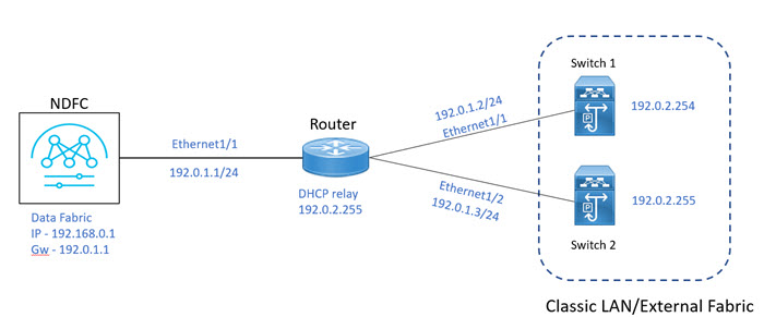
inband-external-lan-classic

Prerequisites

The following are the prerequisites for using Inband Management:

  • Configure appropriate Data Network Routes for reachability to the switch Inband interfaces on Cisco Nexus Dashboard. On Nexus Dashboard, choose Admin Console > Infrastructure > Cluster Configuration. On General tab, enter route IP addresses.

  • On NDFC Web UI, navigate to Server settings > Admin and choose Data from LAN Device Management Connectivity drop-down list to manage easy fabrics through inband management, or an error message is displayed. If you choose Data, ensure that the required 'Data Service IPs' are available in the Nexus Dashboard External Service Pools tab.


    Note


    When server settings changed from Data to Management or vice-versa, allow some time for syslog or poap functionalities to be online and ensure that the IP addresses in Cluster configuration are moved to the appropriate pool.


Guidelines and Limitations

The following are the guidelines and limitations for Inband Management:

  • Both Inband and out-of-band switches in the same fabric is not supported.

  • When you add switches to fabric, ensure that the switches are not in maintenance mode.

Inband POAP Management in External Fabrics and LAN Classic Fabrics

Inband POAP

Power On Auto Provisioning (POAP) automates the process of upgrading software images and installing configuration files on devices that are deployed on the network for the first time. POAP allows devices to bring up without performing any manual configuration.

When a POAP feature enabled device boots and does not find the startup configuration, the device enters POAP mode, locates a DHCP server, and bootstraps itself with its interface IP address, gateway, and DNS server IP addresses. The device obtains the IP address of a TFTP server and downloads a configuration script that enables the switch to download and install the appropriate software image and configuration file.

By using the POAP (Power On Auto Provisioning) feature of Nexus switches, Cisco NDFC (Nexus Dashboard Fabric Controller) can automate the deployment of new datacenters reducing overall time and effort.

Starting NDFC 12.1.1e, External Fabrics and LAN Classic fabrics support adding switches through POAP from inband interfaces.

The Inband POAP is supported for all the roles for fabrics with External and LAN Classic templates.

Prerequisites

The following are the prerequisites for using Inband poap:

  • Configure appropriate Data Network Routes for reachability to the switch Inband interfaces on Cisco Nexus Dashboard. On Nexus Dashboard, choose Admin Console > Infrastructure > Cluster Configuration. On General tab, enter route IP addresses.

  • On NDFC Web UI, navigate to Server settings > Admin and choose Data from LAN Device Management Connectivity drop-down list to manage easy fabrics through inband management, or an error message is displayed. If you choose Data, ensure that the required 'Data Service IPs' are available in the Nexus Dashboard External Service Pools tab.


    Note


    When server settings changed from Data to Management or vice-versa, allow some time for syslog or poap functionalities to be online and ensure that the IP addresses in Cluster configuration are moved to the appropriate pool.


  • Inband POAP on Bootstrap tab is supported only when Inband Management is enabled on Advanced tab in the Fabric settings.

    Each subnet for the defined DHCP subnet scope that is mentioned in fabric settings must have a valid route for reverse traffic.

    Ensure that the DHCP relay functionality is set on intermediate routers.

Guidelines and Limitations

The following are the guidelines and limitations for Inband POAP:

  • Inband POAP is supported for NX-OS switches only.

  • You can enable Inband POAP with NDFC as a Local DHCP Server or on External DHCP Servers.

  • Inband POAP supports Multi Subnet scope.

  • Inband POAP requires the external router connected seed switches to have the following capabilities:

    • DHCP relay functionality

    • eBGP peering

Enabling Inband Management and POAP on External Fabrics and LAN Classic Fabrics

inband-poap-fabrics-settings

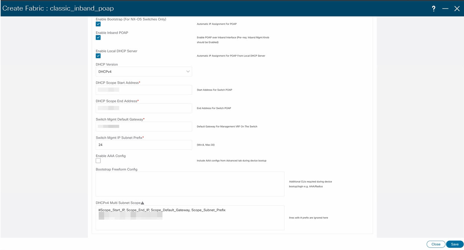
To enable Inband POAP on a fabric, perform the following steps:

Procedure

Step 1

On the Advanced tab, check Inband Mgmt check box.

Step 2

On Bootstrap tab, do the following:

  • Check Enable Bootstrap check box.

  • Check Enable Local DHCP Server check box and enter appropriate IP addresses in the required fields.


Adding Switches

To add or discover switches through Inband POAP, you must follow below steps:

  1. Pre-provisioning Switches to a Fabric

  2. Add an Interface

  3. Add a policy to fabric

  4. Import switches using Bootstrap Mechanism

Pre-Provisioning Switches to a Fabric
pre-provision-switch-inband

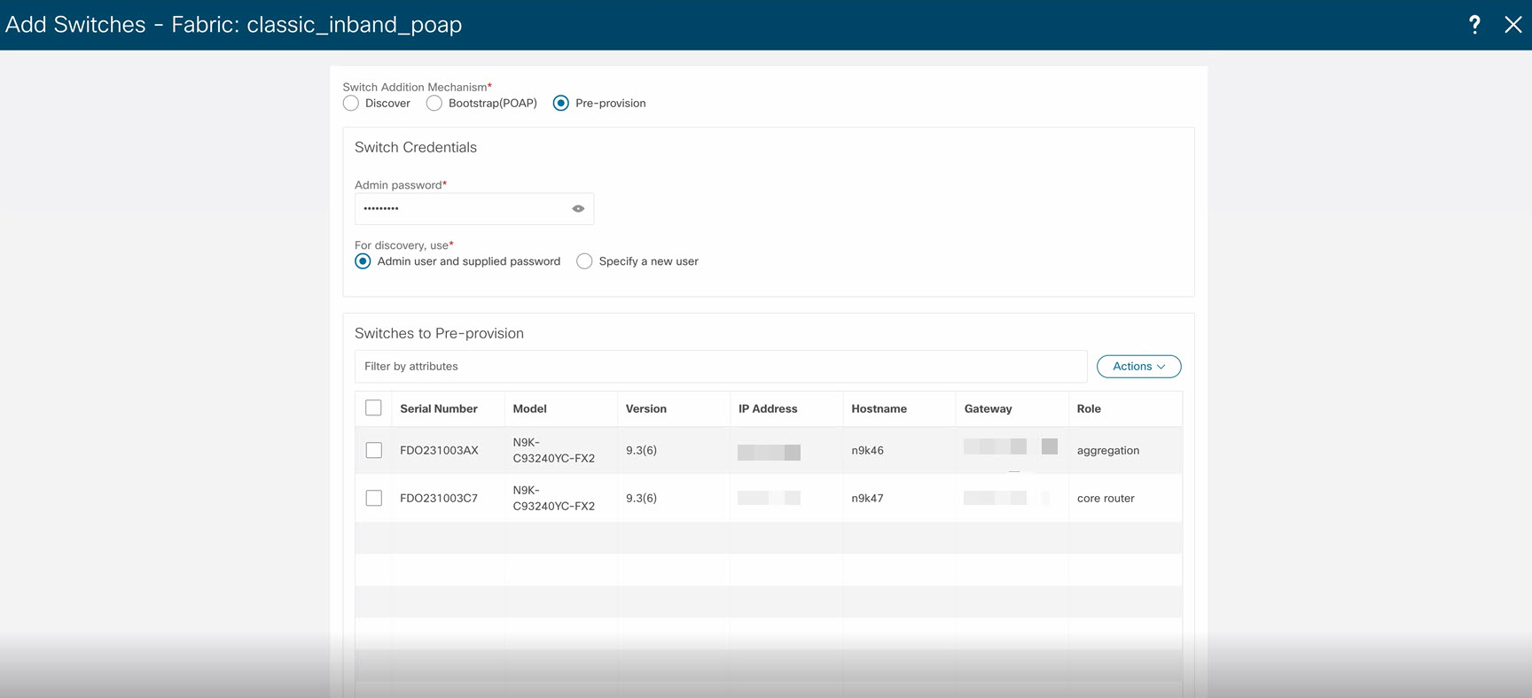
To add switches to fabric, perform the following steps:

Procedure

Step 1

On Fabric window, double-click on appropriate fabric and navigate to Fabric Overview window.

Step 2

Navigate to Switches tab and click Actions > Add Switches.

The Add Switches window appears.

Step 3

Choose Pre-provision radio button.

Step 4

Click Actions and add switches.

You can add switches one at a time using the Add option or add multiple switches at the same time using the Import option.

If you use the Add option, ensure you enter all the required details.

Step 5

Choose a switch.

Step 6

Enter the password in the Admin password field.

Step 7

Click Pre-provision.

The pre-provisioned switch is added.

Note


From Cisco NDFC Release 12.1.1e, for pre-provisioned switches dummy values can be added for the serial number. After configuring the network successfully, you can change serial number with the appropriate number of the switch on the Switches tab. See Change Serial Number section in Performing Actions on Switches.


Importing Switches Using Bootstrap Mechanism
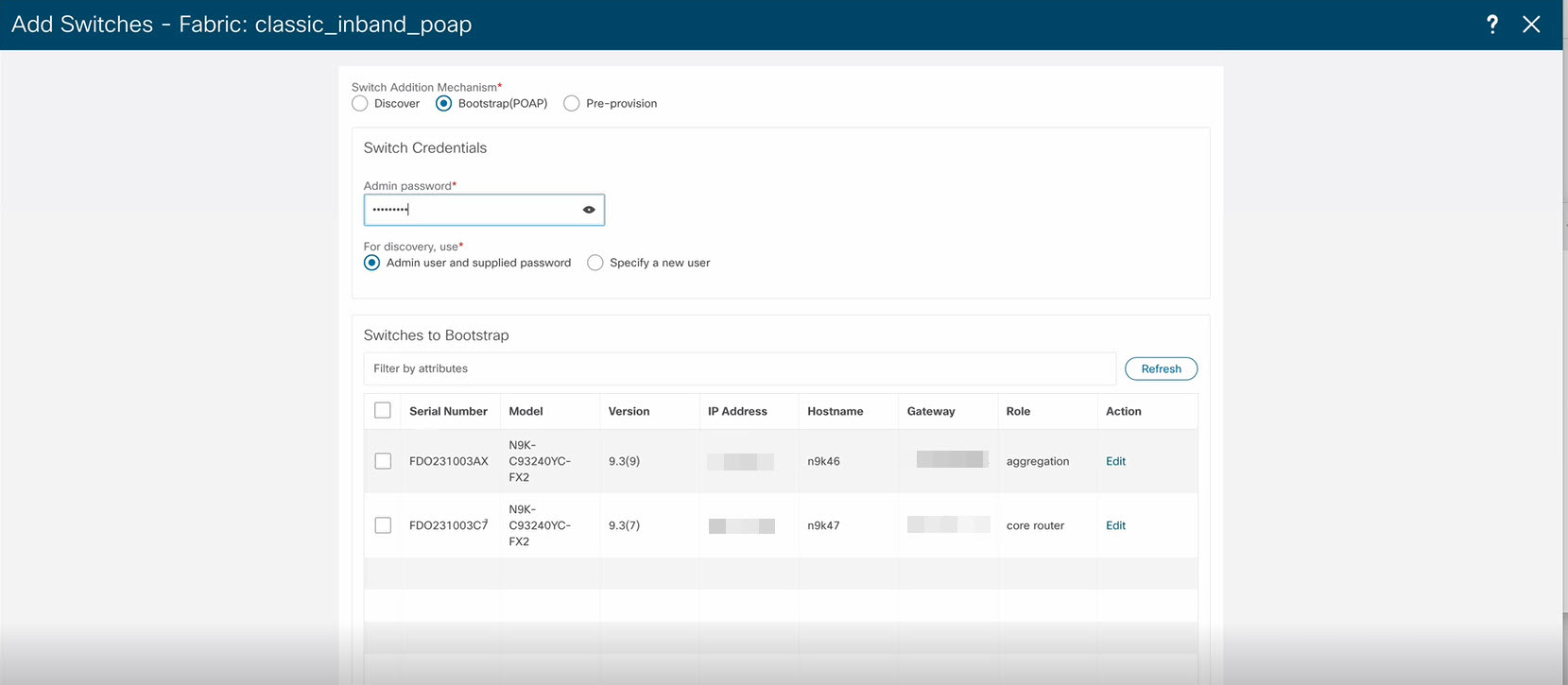
siwtch-bootstrap

Note


Ensure that you have pre-provisioned switches, added interface, and policy before importing the switces using bootstrap mechanism.


To import switches using the bootstrap mechanism.

Procedure

Step 1

On the Fabric Overview window, click Actions > Add Switches.

The Add Switches window appears.

You can view the existing added switches in the Switches to Bootstrap area.

Step 2

Choose Bootstrap (POAP) radio button and enter a password in Admin password field.

Step 3

Choose the required switches and click Import Selected Switches to bootstrap switches.


Adding an Interface

To add the interfaces from the Cisco Nexus Dashboard Fabric Controller Web UI, perform the following steps:

Before you begin

Ensure that you add required configurations on switches such as IP addresses and static routes.

Add an interface to add interface IP addresses on required switch.

Procedure

Step 1

On the Fabric Overview window, navigate to Interface tab.

Step 2

Click Actions > Create Interface.

The Create New Interface window appears.

Step 3

Choose Ethernet type from drop-down list.

Step 4

Choose appropriate switch from Select a device drop-down list and enter a name in Interface name field.

Step 5

Choose int_routed_host policy from the list.

Step 6

Enter the required configuration details in Interface IP and IP Netmask Length fields.

Step 7

Enter appropriate details in mandatory fields and ensure that you check Enable Interface check box and then click Save.


Adding a Policy to a Fabric

You can add a freeform policy to define external routes in the switch. To add a policy, perform the following steps:

Procedure

Step 1

On the Fabric Overview tab, click Policy tab.

Step 2

Choose an appropriate switch in the Switch window and click Choose Template.

Step 3

Choose switch_freeform policy and click Select.

This policy type allows you to add configurations in CLI format.

The Create Policy window appears.

Step 4

Click Actions > Add Policy.

Step 5

Enter the appropriate configuration in Switch freeform configuration field in the window and click Save.


Recalculating and Deploying Configurations on a Switch

To push pending configurations on switches, perform the following steps:

Procedure

Step 1

On Fabric Overview window, navigate to Switches tab.

You can view Config status column displays Pending status.

Step 2

Click Actions > Recalculate and Deploy.

The Deploy Configuration window appears. It displays the configuration status on the switches. You can also view the pending configurations by clicking the respective link in the Pending Config column.

The Pending Config window appears. The Pending Config tab on this window displays the pending configurations on the switch. The Side-by-Side Comparison tab displays the running configuration and expected configuration side by side.

Step 3

Close the Pending Config window.

Step 4

You can view the Config status column displays In-Sync status.


Inband Management and Inband POAP in Easy Fabrics

Starting from Cisco NDFC Release 12.1.1e, you can manage switches with Inband connectivity and Inband POAP for Easy Fabrics. For Inband Management, the Loopback0 interface of the devices is used in the Fabric Settings.

inband-easy-fabric

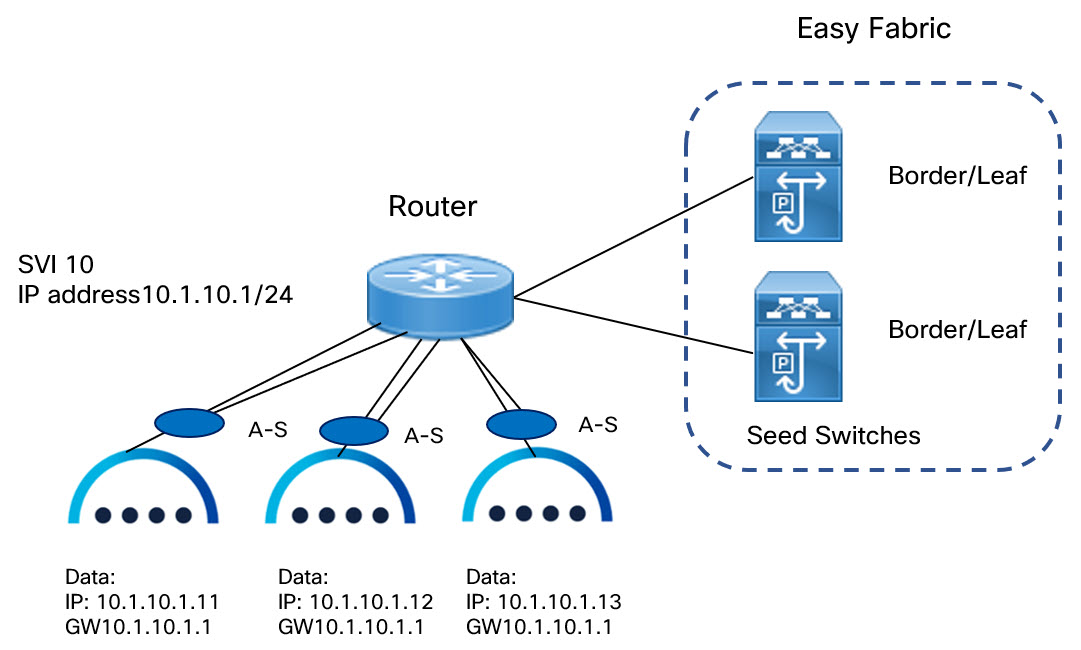
If you want POAP Layer-3 adjacency to switches, you must add Nexus Dashboard Node IP address as DHCP Relay address, perform the following:

  • On NDFC UI, navigate to Settings > Server Settings, click Admin tab. If default value Management is chosen from LAN Device Management Connectivity drop-down list , then DHCP Relay address must be set to the management interface IP (bond1br) in all Nexus Dashboard Nodes.

  • On NDFC UI, navigate to Settings > Server Settings, click Admin tab. If value Data is chosen from LAN Device Management Connectivity drop-down list , then DHCP Relay address must be set to the data interface IP (bond0br) in all Nexus Dashboard Nodes.

You can add switches with Inband Management enabled for easy fabrics either in Greenfield or brownfield deployment with Inband POAP or pre-provision and Inband POAP.

  • For Brownfield deployment, check Preserve Config check box.

  • For Greenfield deployment, uncheck Preserve Config check box.

The seed switches connect the external routers, and it provides management connectivity to the other switches in the fabric. Switches connected to external routers to provide connectivity to the fabrics are termed as seed switches. The interfaces on the seed switches which connects to the external routers are termed as bootstrap interfaces.

Prerequisites for Inband Management

On NDFC Web UI, navigate to Server settings > Admin and choose Data from LAN Device ManagementConnectivity to manage easy fabrics through Inband management. If you choose Data, ensure that the required Data Service IPs are available in the Nexus Dashboard External Service Pools tab.


Note


When server settings changed from Data to Management or vice-versa, allow some time for syslog or poap functionalities to be online and ensure that the IP addresses in Cluster configuration are moved to the appropriate pool.


This server setting is required for both Inband and out-of-band connectivity. Configure below static routes over data interface in Cisco Nexus Dashboard:

Enter static routes IP address required for external route and route over data interface in Cisco Nexus Dashboard.

Inband POAP requires the external router IP address connected to the seed switches to have the following capabilities:

  • Routes for External router

  • Route for Routing Loopback subnet range for Easy Fabric

  • Route for Underlay Routing subnet range for Easy Fabric

Inband POAP requires the external router connected seed switches to have the following capabilities:

  • DHCP relay functionality

  • eBGP peering

To add switches for Inband Management and Inband POAP, see Discovering New Switches.

Guidelines and Limitations

The following are the guidelines and limitations for Inband Management:

  • Ensure that the Inband Management is enabled for Inband interface. Both Inband and out-of-band switches for a same fabric is not supported.

  • It is supported only for IPv4 underlay and OSPF routing protocol.

  • You can change switch management from Inband to out-of-band and conversely after creating a fabric.

  • For the Inband managed switches, the following roles are supported:

    • Spine

    • Leaf

    • Border

    • Border Spine

    • Border Gateway

    • Border Gateway Spine

  • Inband management is supported for both numbered and unnumbered fabric interface numbering

  • Ensure that the same role switches are assigned as seed switches. If spine role switch is assigned as a seed switch, all the spine role switches in that fabric must be assigned as seed switches. It is recommended to assign switch as seed switches.

  • When you add switches to fabric, ensure that the switches are not in maintenance mode.

  • You can add switches in Brownfield deployment (check Preserve Config check box) only when the fabric is created. To add more switches, use Inband POAP with import switches option.

  • Set vPC Peer Keep Alive option to loopback if the vPC switches mgmt0 interfaces are not configured.

The following are the guidelines and limitations for Inband POAP:

  • Inband POAP for a fabric can be enabled only if Inband Management is enabled.

  • Inband POAP requires the fabric or core facing interfaces to be cabled consistently for seed switches and spine switches.

  • All spine switches in fabric must use same set of fabric interface numbers.

  • If a fabric has set of leaf switches which are seed switches, then the switches must use same fabric interface number.

  • The seed switches must have eBGP peering with the external router. Therefore, the external router must have the required eBGP route peering capabilities and display the configuration for External router for DHCP relay and Static routes configured for the Subnets used in Easy Fabrics.

  • DHCP relay must be configured on external routers interface which connects the seed switch in Inband interfaces. Ensure that the DHCP relay destination configured is same for all cluster node data interface on Cisco Nexus Dashboard.

  • DHCP server can be internal NDFC or the external server.

Enabling Inband POAP on Easy Fabrics

To enable Inband POAP on Easy Fabrics, perform the following steps:

Procedure

Step 1

On the Manageability tab check Inband Management check box.

Step 2

On Bootstrap tab, do the following:

  1. Check Enable Bootstrap check box.

  2. Check Enable Local DHCP Server checkbox to assign NDFC as DHCP Server and enter the DHCP scopes for all the fabric seed switches bootstrap interfaces.

    If you choose Enable Local DHCP Server, and choose unnumbered in Fabric Interface Numbering drop-down list in the General Parameters tab, add details for:

    • Bootstrap Seed Switch Loopback Interface ID

    • Switch Loopback DHCP Scope Start Address

    • Switch Loopback DHCP Scope End Address

  3. Check External DHCP Server IP Addresses check box to provide connectivity to NDFC from the external router.

    If you choose External DHCP Server IP Addresses, you can add a maximum of three IPv4 addresses with a comma separated list.

    Note


    To have eBGP peering between seeds and an external router, add bootstrap seed switch loopback interface IP address, this IP must be a subset of the loopback id range.

  4. Enter Seed Switch interface in Seed Switch Fabric Interfaces text field.

  5. Enter Spine Switch interface in Spine Switch Fabric Interfaces text field.

    Note


    If the Spine switches are the seed switches, then the lists must be consistent in Seed Switch Fabric Interfaces text field.

Step 3

For fabrics with unnumbered interface, do the following:

  1. On General Parameters, choose unnumbered from Fabric Interface Numbering drop-down list.

  2. On Bootstrap tab:

    Bootstrap Seed Switch Loopback Interface ID the loopback ID is the default router IP for the fabric. This loopback ID must not overlap with any of the existing fabric loopback IDs.

    Switch Loopback DHCP Scope Start Address this IP address is start address of the DHCP pool of the routing loopback addresses range to assign to the bootstrapping switch. This IP address must not overlap with any of the existing IP addresses of Underlay Routing Loopback IP Range.

    Switch Loopback DHCP Scope End Address is the end address of the DHCP pool.


Importing Switches to Brownfield Deployment

Before you begin

Make sure that you follow prerequisites procedure before adding switches.

Procedure

Step 1

Create a fabric using a template Data Center VXLAN EVPN. For instructions, see Create a Fabric.

Ensure that you add switches in the order of Seed switches, Spine switches, and other switches. You can add spine switches as the seed switches.

Step 2

In Brownfield deployment for each fabric, enable Inband Management on the Manageability tab and import the fabric.

Step 3

Add the switches to the fabric with the Preserve Config check box.

Step 4

Enter hostname, Role, enable Seed Switch, and enter appropriate IP address.

Step 5

Enter the IP addresses for all the seed switches, click Import Selected Switches to add them to the fabric.

Step 6

Navigate to Policy tab, click Actions > Add Policy. Choose ext_bgp_neighbor policy so the seed switches establish eBGP peering. Enter the required details, and click Save.

Step 7

Assign the appropriate switch roles.

For more instructions, see Adding Switches Using Bootstrap Mechanism.


Pre-provisioning switches through Inband POAP

Procedure

Step 1

On Switches tab, choose Actions > Add Switches.

The Add Switches window appears.
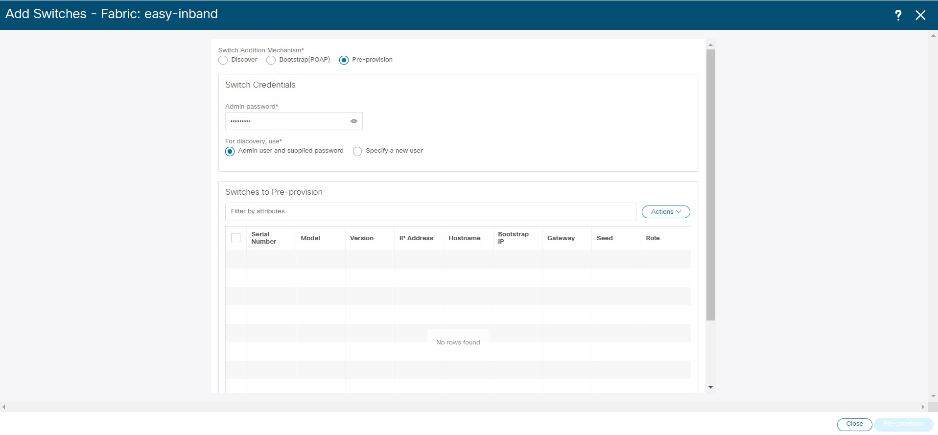
Step 2

Choose Pre-provision radio button.

Step 3

On Switches to Pre-provision table, click Actions> Add.

The Pre-provision a switch window appears.

Step 4

Enter appropriate details such as Serial Number, Model, IP Address, and click Add.

Step 5

Enter single switch at once and enter the required information. If you have multiple switches.

Step 6

Click Import Switches to Fabric to add switches.


Adding policy for Easy Fabric

Procedure

Step 1

Navigate to LAN > Fabrics window, double-click on appropriate easy fabric to add policy.

The Fabric Overview window appears.

Step 2

On Fabric Overview tab, click on Policy tab.

Step 3

Choose appropriate switch from Switch window and click Choose Template.

Step 4

Choose ext_bgp_neighbor policy and click Select.

The Create Policy window appears.

Step 5

Click Actions > Add Policy.

The Create Policy window appears.

Step 6

Enter the appropriate details in the window and click Save.

Step 7

On Fabric Overview window, click Actions > Recalculate and Deploy.


Changing Fabric Management Mode

You can change the fabric from out-of-band to Inband Management and conversely.

Procedure

Step 1

To change fabric management from out-of-band to Inband Management, perform the following steps:

  1. Ensure that you follow prerequisite procedure for Inband Management.

  2. In Edit Fabric window, enable Inband Mgmt on the Advanced tab and click Save.

  3. On Fabric Overview > Switches tab, choose switch and choose Actions >Change Mode, the mode column display Migration.

  4. Choose switches. Click Actions > Recalculate and Deploy.

    The discovery IP address of the switches changes to the BGP routing loopback IP.

    The discovery VRF displays default and discovery interface is updated to BGP routing loopback interface.

    An error is generated displaying switch discovery is pending. "The discovery modes for switches have been updated but, discovery may not have completed. Please check to make sure Discovery Status is Ok and retry Recalculate & Deploy".

    Click OK.

  5. Ensure that the Discovery Status column display status OK, then click Actions > Recalculate and Deploy.

Step 2

To change fabric management from Inband Management to out-of-band, perform the following steps:

  1. Ensure that you follow prerequisite procedure for out-of-band.

  2. Configure out-of-band IP addresses on the switch and this IP must be reachable from NDFC data or Management interface.

  3. Choose fabric, click Actions > Edit Fabric.

  4. On Advanced tab, uncheck Inband Management check box and click Save.

  5. On Fabric Overview > Switches tab, choose switch and choose Actions >Change Mode, the mode column displays Migration.

  6. Choose switches. Click Actions > Recalculate and Deploy.

    The discovery IP address of the switches will be changed to the mgmt0 IP.

    The discovery VRF displays management and discovery interface will be updated to mgmt0.

    An error is generated displaying switch discovery is pending. "The discovery modes for switches have been updated but, discovery may not have completed. Please check to make sure that Discovery Status is Ok and retry Recalculate & Deploy".

    Click OK.

  7. Ensure that the Dcovery Status column displays status OK, then click Actions > Recalculate and Deploy.


Secure POAP

When you import switches through bootstrap or POAP in NDFC, it locates a DHCP protocol and bootstraps with interface IP address, gateway, DNS server IP address, and POAP script path. Before NDFC Release 12.1.2e, this was hosted through an HTTP or TFTP server.

From Cisco NDFC Release 12.1.2e, POAP uses an HTTPS server which is a secure protocol to encrypt traffic and validate NDFC for network connection. You must configure Bench Router (BR) to host (R)oot Certificate Authority (CA), which is a signed server certificate of POAP server that is hosted on NDFC. In the DHCP response, BR is identified which acts as a trust for a new switch.


Note


Secure POAP is not supported for inband connectivity with bench routers.


See CA Certificates and POAP Certificates to upload appropriate certificates on NDFC.

Prerequisites for Secure POAP

  • Secure POAP is supported from Cisco NX-OS 9000 Release 10.2.3 or higher version switches.

  • On NDFC Web UI, navigate to Server Settings, click LAN tab, and choose https or http&https from the drop-down list for Bootstrap Script Download Protocol field.

  • For http or http&https option, you must enter IP address of bench router (BR), port number, and name for certificate bundle in Bench Router URL with port and certificate file name filed. Ensure that the certificates are uploaded on NDFC server for values to autopopulate in this field.

  • By default, for http or http&https option Bench Router URL with port and certificate file name field in the Server setting will be blank. After you install the Root CA Certificate bundle on Bench routers, this field will be autopopulated.

    If these fields are autopopulated, with default port number 29151 and URL https://10.10.10.1:29151/PoapCACertBundle.pem, you must configure this URL before you install BR with the Root CA certificate bundle.

  • Make sure that the Fabric is in managed mode before configuring BR.

  • Ensure that you configure DHCP option if the DHCP server is used.

  • You must upload CA signed POAP server certificate on NDFC and upload the corresponding CA certificate bundle for the BR. On NDFC, navigate to Operations > NXAPI Certificates to upload relevant certificates.
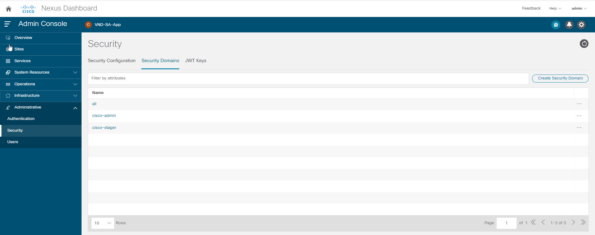
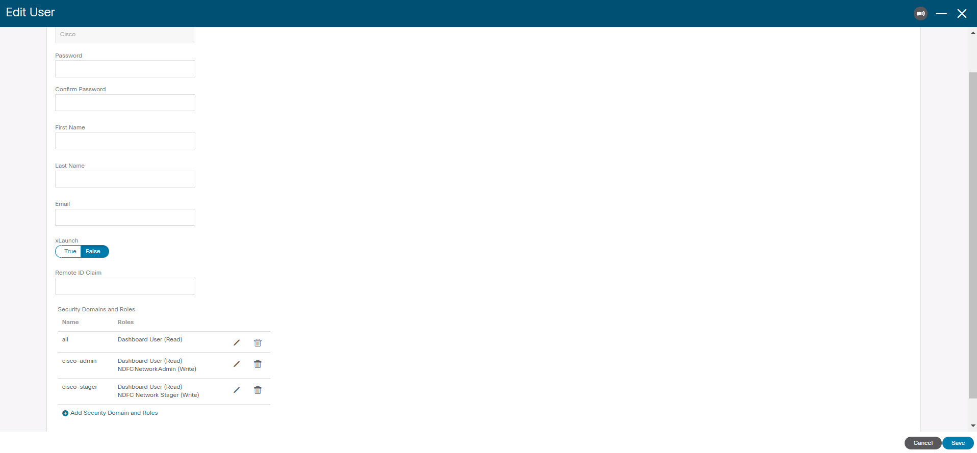
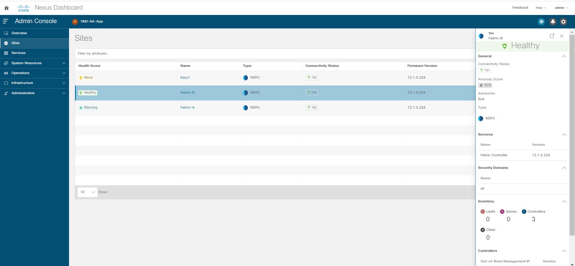
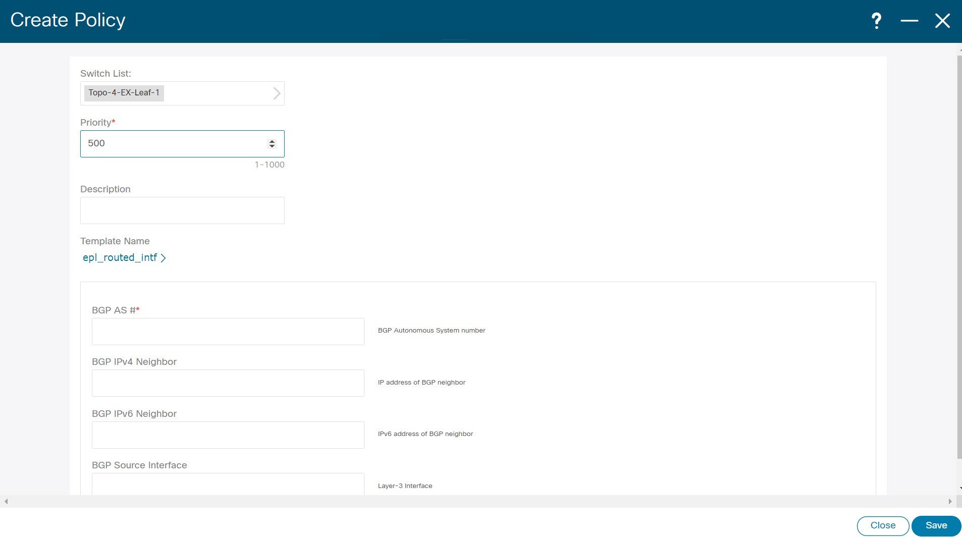
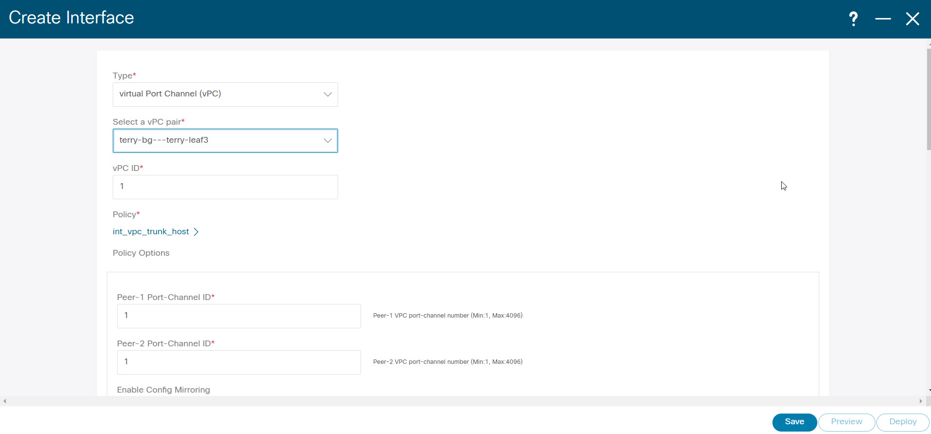
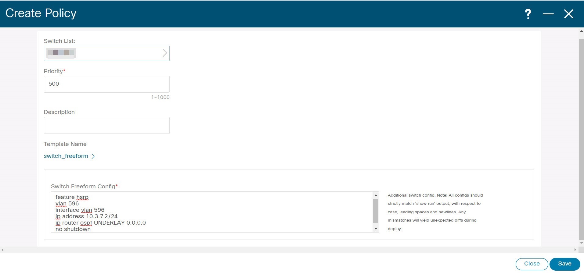
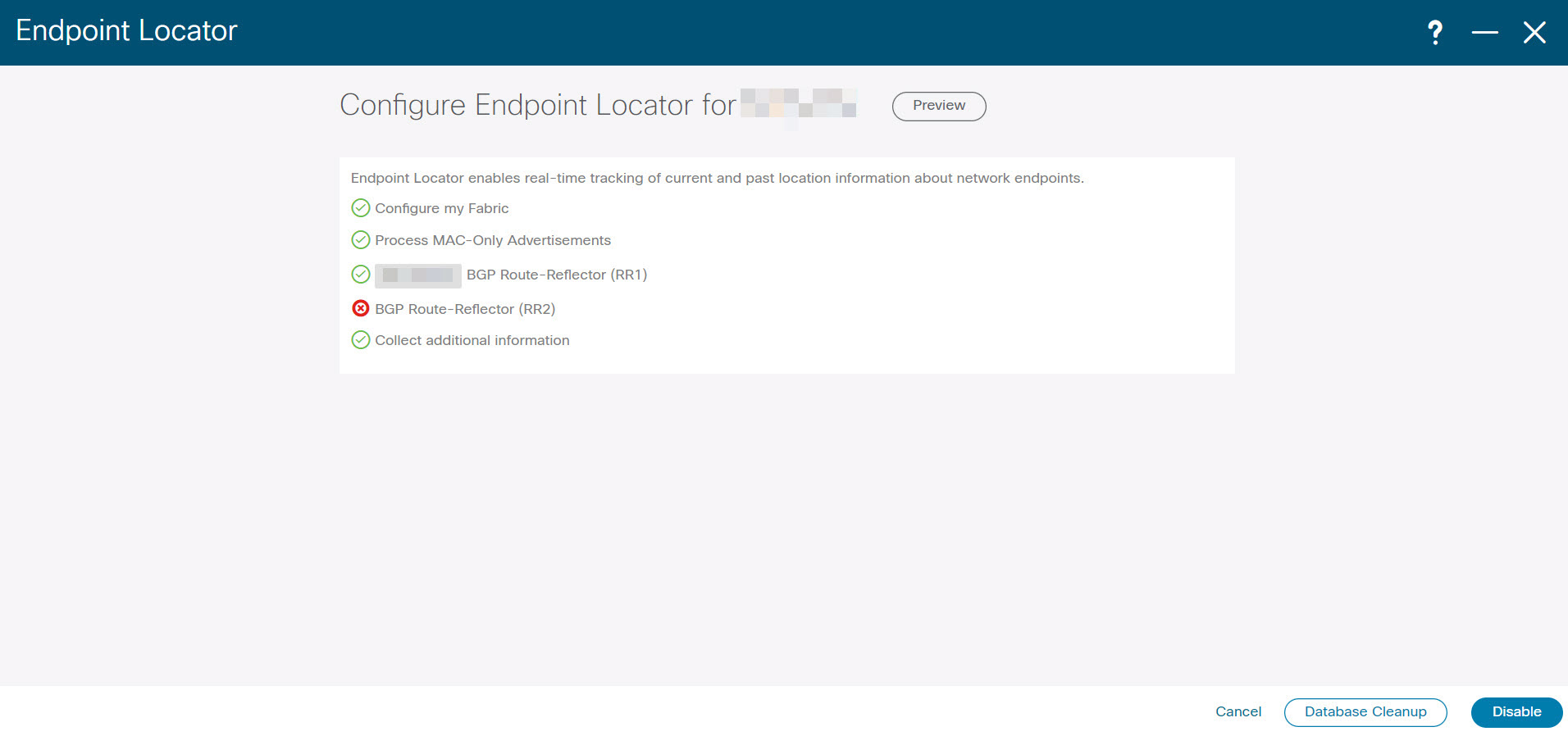
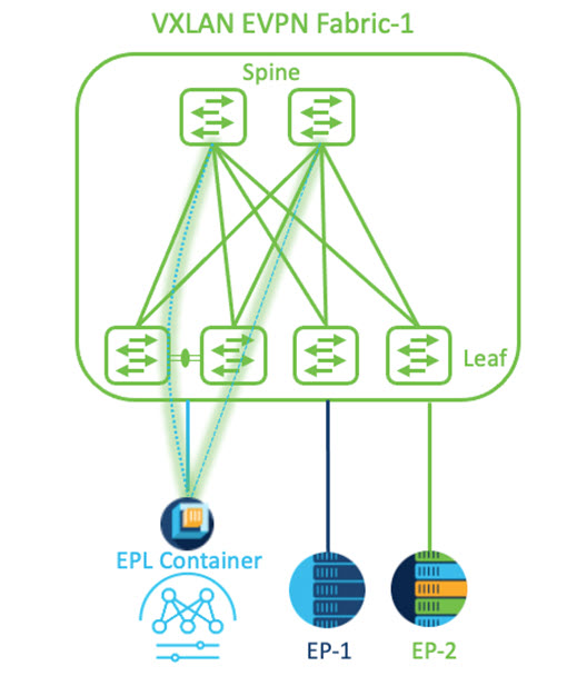
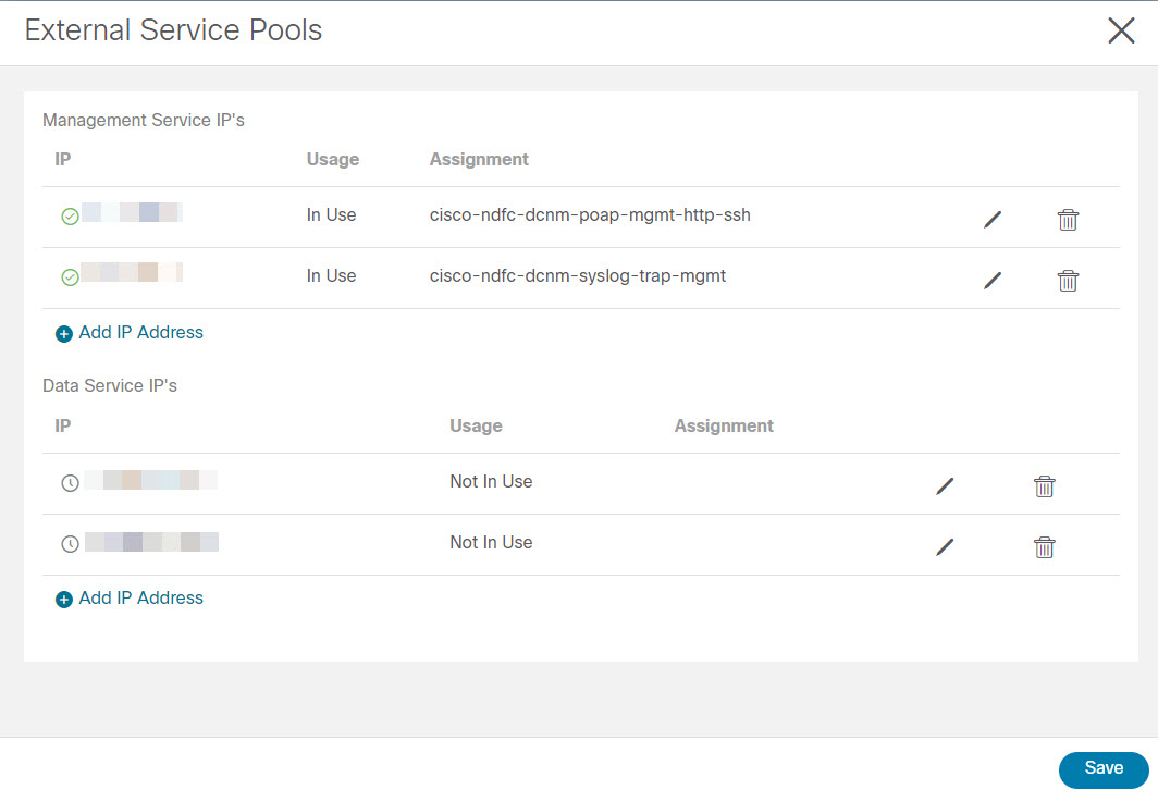
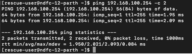
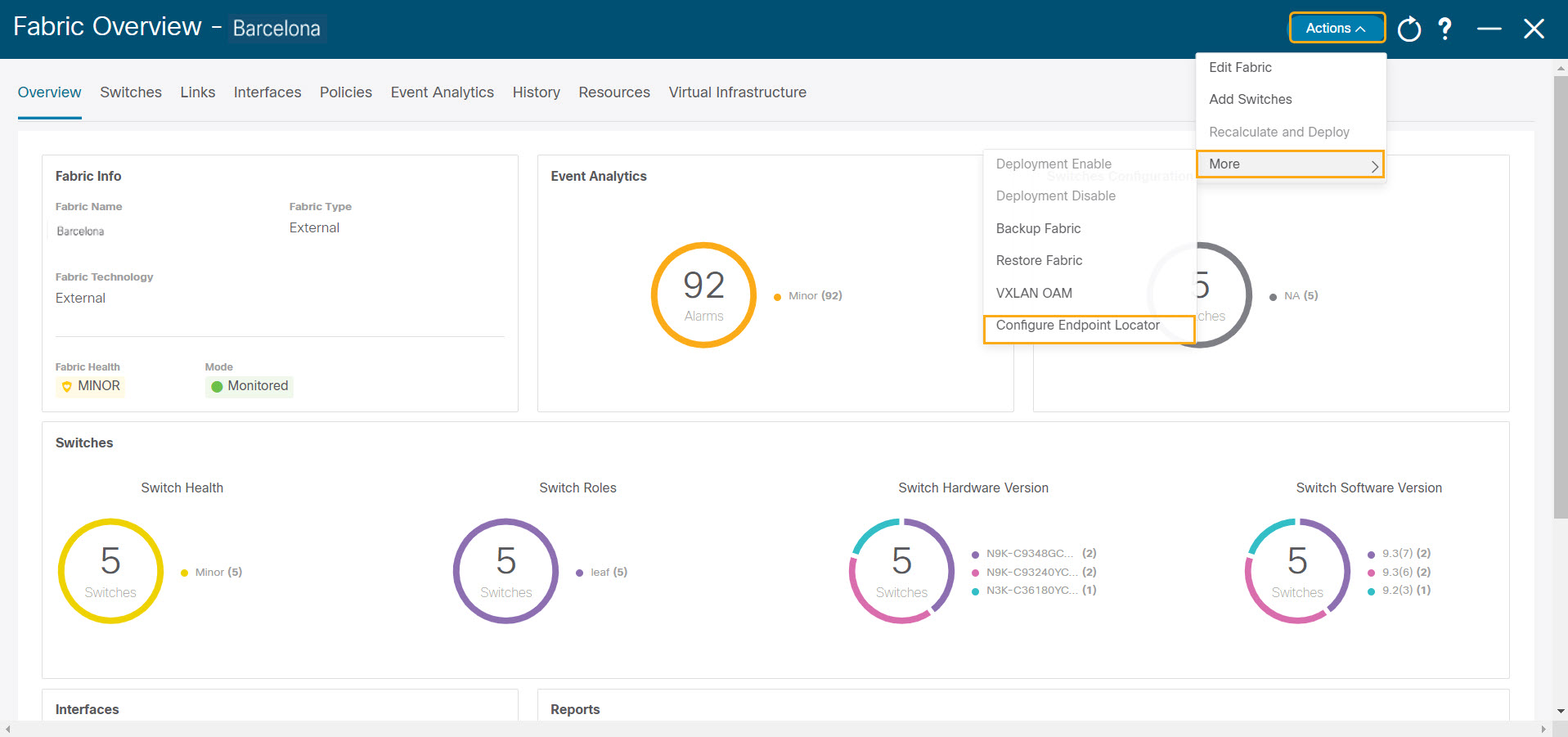
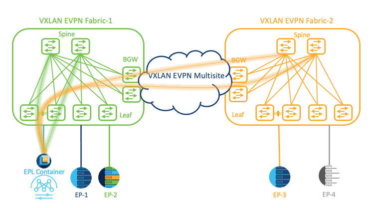
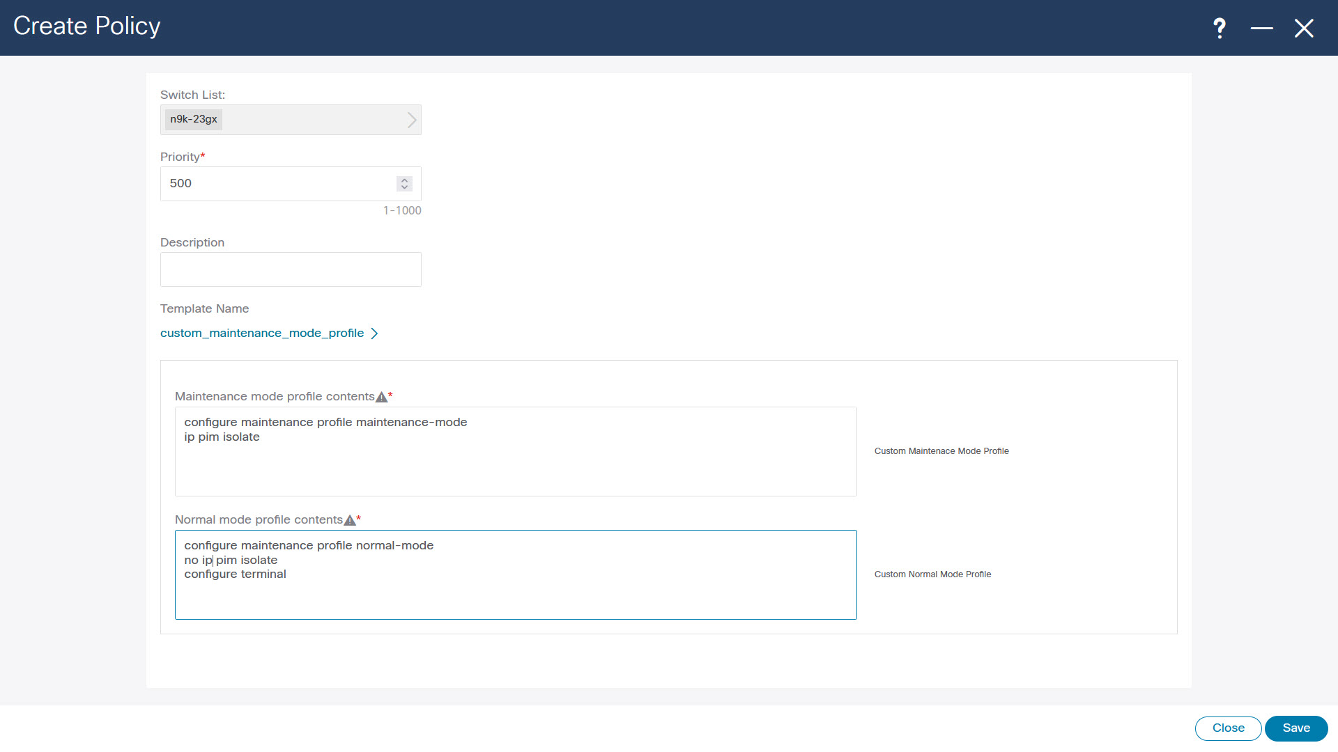
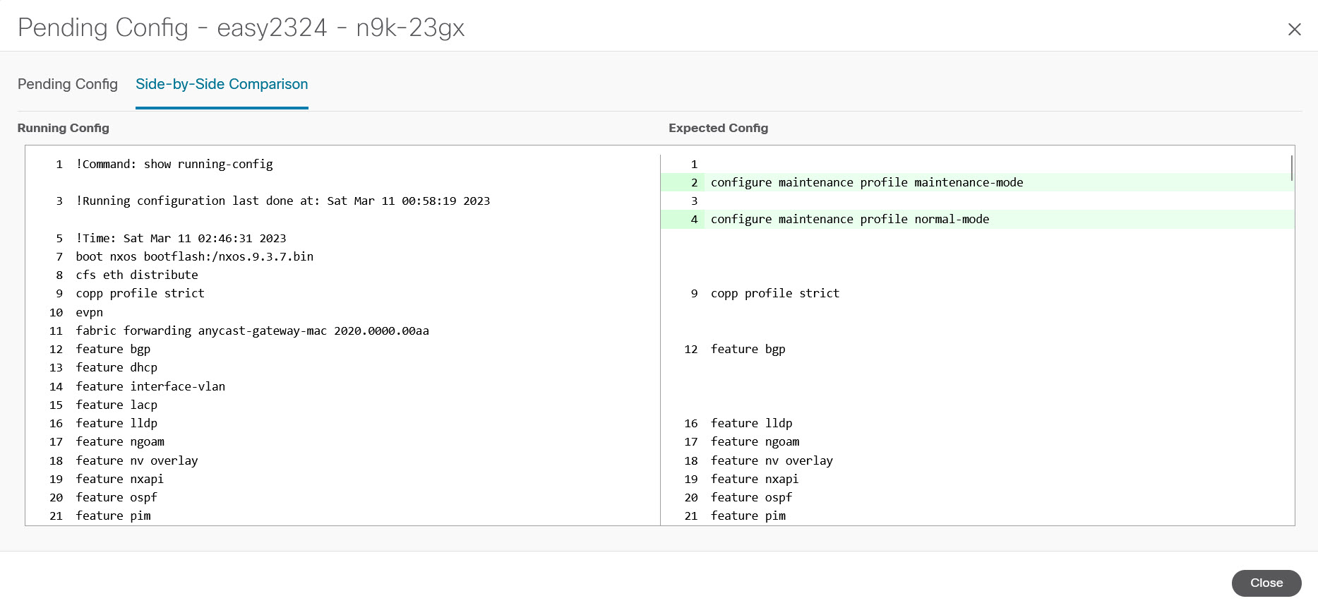
Enhanced Role-based Access Control

Starting from Cisco Nexus Dashboard Fabric Controller Release 12.0.1(a), all RBAC is in Nexus Dashboard. User-roles and access are defined from Nexus Dashboard for fabrics on NDFC.

Nexus Dashboard admin role is considered as Network-admin role in NDFC.

DCNM had five roles to perform various access and operations. If a user is access a fabric with network stage role has access to all other fabrics as a network stage role. Therefore, a username is restricted with their role in DCNM.

Cisco NDFC Release 12.0.1(a) has same five roles but you can do granular RBAC with integration of Nexus Dashboard. If a user accesses a fabric as a network stage role, the same user can access different fabric with other user role such as admin or operator role. Therefore, a user can have different access on the different fabrics in NDFC.

NDFC RBAC supports following roles:

  • NDFC Access Admin

  • NDFC Device Upgrade Admin

  • NDFC Network Admin

  • NDFC Network Operator

  • NDFC Network Stager

The following table describes the user roles and their privileges in NDFC.

Roles

Privileges

NDFC Access Admin

Read/Write

See

NDFC Device Upgrade Admin

Read/Write

NDFC Network Admin

Read/Write

NDFC Network Operator

Read

NDFC Network Stager

Read/Write

The following roles are supported on DCNM for backward compatibility:

  • Global-admin (mapped to network-admin)

  • Server-admin (mapped to network-admin)


Note


In any window, the actions that are restricted by the user role that is logged in are grayed out.


NDFC Network Admin

A user with the NDFC Network Admin role can perform all the operations in Cisco Nexus Dashboard Fabric Controller.

From Cisco Nexus Dashboard Fabric Controller Release 12.1.1e, a user with this role can perform all operations for MSD fabrics in Networks and VRFs.

You can freeze a particular fabric or all fabrics in Cisco Nexus Dashboard Fabric Controller if you are a user with the NDFC Network Admin role.


Note


Make sure that the switch user role for discovery or add switches or LAN credentials for NDFC must have the network-admin role.


NDFC Device Upgrade Admin

A user with the NDFC Device Upgrade Admin role can perform operations only in Image Management window.

See the Image Management section for more information.

NDFC Access Admin

A user with the NDFC Access Admin role can perform operations only in Interface Manager window for all fabrics.

An NDFC access admin can perform the following actions:

  • Add, edit, delete and deploy layer 2 port channels, and vPC.

  • Edit host vPC, and ethernet interfaces.

  • Save, preview, and deploy from management interfaces.

  • Edit interfaces for LAN classic, and IPFM fabrics.

    Apart from nve, management, tunnel, subinterface, SVI, interface grouping, and loopback interfaces

However, a user with the Cisco Nexus Dashboard Fabric Controller access admin role can’t perform the following actions:

  • Cannot edit layer 3 port channels, ST FEX, AA FEX, loopback interfaces, nve interfaces, and subinterfaces.

  • Cannot edit member interfaces and port channels of Layer 3, ST FEX, AA FEX.

  • Cannot edit interfaces with policy associated from underlay and link for easy fabrics.

  • Cannot edit peer link port channel.

  • Cannot edit management interface.

  • Cannot edit tunnel.


Note


The icons and buttons are grayed out for this role when the fabric or Cisco Nexus Dashboard Fabric Controller is in deployment-freeze mode.


NDFC Network Stager

A user with the NDFC Network Stager role can make configuration changes on Cisco Nexus Dashboard Fabric Controller. A user with the NDFC Network Admin role can deploy these changes later. A network stager can perform the following actions:

  • Edit interface configurations

  • View or edit policies

  • Create interfaces

  • Change fabric settings

  • Edit or create templates

However, a network stager cannot perform the following actions:

  • Cannot make any configuration deployments to switches.

  • Cannot perform deployment-related actions from the Cisco Nexus Dashboard Fabric Controller Web UI or the REST APIs.

  • Cannot access the administration options like licensing, creating more users, and so on.

  • Cannot move switches in and out of maintenance mode.

  • Cannot move fabrics in and out of deployment-freeze mode.

  • Cannot install patches.

  • Cannot upgrade switches.

  • Cannot create or delete fabrics.

  • Cannot import or delete switches.

NDFC Network Operator

A network operator can view fabric builder, fabric settings, preview configurations, policies, and templates. However, a network operator cannot perform the following actions:

  • Cannot change expected configurations of any switch within any fabric.

  • Cannot deploy any configurations to switches.

  • Cannot access the administration options like licensing, creating more users, and so on.

The difference between a network operator and a network stager is that, as a network stager you can only define intent for existing fabrics, but cannot deploy those configurations.

Only a network admin can deploy the changes and edits that are staged by a user with the network stager role.

Choosing Default Authentication Domain

By default login screen on Nexus Dashboard chooses the local domain for authentication. You can change domain at login time by choosing available domains from drop-down list.

Nexus Dashboard supports local and remote authentication. The remote authentication providers for Nexus Dashboard include RADIUS, and TACACS. For more information on authentication support, refer https://www.cisco.com/c/en/us/td/docs/dcn/nd/2x/user-guide/cisco-nexus-dashboard-user-guide-211.pdf.

The following table describes RBAC comparison between DCNM and NDFC access:

DCNM 11.5(x) NDFC 12.0.x and 12.1.x
  • User has a single role.

  • All APIs and resources are accessed with this single role.

  • User can have a different role in different Nexus Dashboard for security domains.

  • Security domain contains single Nexus Dashboard, and each Nexus Dashboard contains single NDFC Fabric.

A single role is associated with the user by disabling or restricting the access to options in DCNM.

A single role displays only privileged resources on the selected page and restricted access are grayed out based on security domain associated with selected resource on further options on NDFC.

DCNM AV Pair format with shells, roles, and optional access constraints.

Nexus Dashboard AV Pair format with shells, domains.

Supported roles based on deployment type LAN, SAN, or PMN.

Supported roles such as network-admin, network-operator, device-upg-admin, network-stager, access-admin are in NDFC.

Support for legacy roles for backward compatibility. Nexus Dashboard admin role as network-admin of DCNM.

The following table describes DCNM 11.5(x) AV Pair format:

Cisco DCNM Role RADIUS Cisco-AV-Pair Value TACACS+ Shell Cisco-AV-Pair Value

Network-Operator

shell:roles = "network-operator" dcnm-access="group1 group2 group5"

cisco-av-pair=shell:roles="network-operator" dcnm-access="group1 group2 group5"

Network-Admin

shell:roles = "network-admin" dcnm-access="group1group2 group5"

cisco-av-pair=shell:roles="network-admin" dcnm-access="group1 group2 group5"

The following table describes NDFC 12.x AV Pair format:

User Role AVPair Value

NDFC Access Admin

Access-admin

NDFC Device Upgrade Admin

Device-upg-admin

NDFC Network Admin

Network-admin

NDFC Network Operator

Network-operator

NDFC Network Stager

Network-stager

The AV pair string format differs when configuring a read/write role, read-only role, or a combination of read/write and read-only roles for a specific user. A typical string includes the domain, followed by the read-write roles separated from the read-only roles using the slash (/) character; individual roles are separated by the pipe (|) character:

shell:domains=<domain>/<writeRole1>|<writeRole2>/<readRole1>|<readRole2>

Enhanced RBAC Use-Cases

There are various fabrics in NDFC. By default a user is an admin for all the fabrics. For an example, a username Cisco can have admin role access to a Fabric-A and stager role access to another Fabric-B.

On Nexus Dashboard, all security policies are part of security domains. You can create the user and give access to these security domains.

To create a user and define specific roles, perform the following steps:

Procedure


Step 1

To create user in security domains:

Security-domain
  1. Log in to Nexus Dashboard with admin role and navigate to Administrative tab.

  2. On Security Domain tab, click Create Security Domain and create the following security domains:

  • all - Similar to network-admin role. This domain has administrative access to Nexus Dashboard and NDFC service application.

  • cisco-admin - full network-admin access to Fabric-A

  • cisco-stager - network-stager only access to Fabric-B

Step 2

To create a local user Cisco.

  1. Navigate to Users > Local.

  2. On Local tab, click Create Local User.

    The Create Local User window appears.

  3. Enter Cisco in User ID text field, provide appropriate passwords in respective fields.

  4. After you create a Cisco user, navigate to Local window, click on elipses icon in Cisco username row and then click Edit User.

    The Edit User window appears.

Step 3

On Edit User window, by default, all security domain exists. Click Add Security Domain and Roles to add other security domains.

The Add Security Domain and Roles window appears.

Edit-user
  1. Choose cisco-admin domain from option drop-down list and choose NDFC Access Admin check box and then click Save.

  2. Repeat step a to add cisco-stager domain for NDFC Network Stager role.

  3. To associate security domains to respective fabric sites, do the following:

    Sites

    On Nexus Dashboard, navigate to Sites window. Click on Fabirc-A site name.

    A slide-in pane appears. You can view all security domain for the Fabric-A site.

  4. To add the Cisco user as network-admin for Fabric-A, click Elipse icon and Edit Site.

  5. Delete all security domain and add network-admin domain and save the changes.

    Similarly you can add for network-stager domain.

  6. Log out from Nexus Dashboard and log in back as Cisco user.

    Note


    The user role Cisco can view only NDFC related options on Nexus Dashboard based on the permissions. The user access restricted to Nexus Dashboard services.

  7. Naviage to NDFC application.

    The user Cisco can perform operations on two sites on NDFC, as the user is assigned as network-admin role for Fabric-A and network-stager role for Fabric-B.

    Note


    Network-admin role can create an interface for Fabric-A and deploy it. Whereas network-stager role can create interface for Fabric-B, but access restricted to deploy.


Nexus Dashboard Security Domains

Access control information about a user login contains authentication data like user ID, password, and so on. Based on the authorization data, you can access resources accordingly. Admins in Cisco Nexus Dashboard can create security domains and group various resource types, resource instance, and map them into a security domain. The admins define an AV-pair for each user, which defines the access privileges for users to different resources in Cisco Nexus Dashboard. When you create a fabric, a site is created in Nexus Dashboard with the same fabric name. You can create and view these sites from Nexus Dashboard > Sites.

The Cisco Nexus Dashboard Fabric Controller REST APIs use this information to perform any action by checking the authorization.


Note


When accessing REST APIs, you can verify passed payload in JSON format. Ensure that the payload is an appropriate JSON format.


When you upgrade from Cisco Nexus Dashboard Fabric Controller Release 11.x, each fabric is mapped to an autogenerated site of the same name. All these sites are mapped into the all security domain in Nexus Dashboard.

All resources are placed in all domain before they are assigned or mapped to other domains. The all security domain does not include all the available security domains in Nexus Dashboard.

AV-Pairs

A group of security domains along with read and write roles for each domain are specified using AV-pairs. Administrators define AV-pair for each user. The AV-pair defines the access privileges to users across various resources in Nexus Dashboard.

The AV-pair format is as follows:

"avpair": "shell:domains=security-domain/write-role-1|write-role-2,security-domain/write-role-1|write-role2/read-role-1|read-role-2"
For example: "avpair":
"shell:domains=all/network-admin/app-user|network-operator". "all/admin/" makes user super-user and it's best to avoid examples with all/admin/"

The write role is inclusive of read role as well. Hence, all/network-admin/ and all/network-admin/network-admin are the same.


Note


From Cisco Nexus Dashboard Fabric Controller Release 12.0.1a supports the existing AV-pair format that you created in Cisco Nexus Dashboard Fabric Controller Release 11.x. However, if you are creating a new AV-pair, use the format that is mentioned above. Ensure that the shell: domains must not have any spaces.


Specifying Cisco NX-OS User Roles and SNMPv3 Parameters on AAA Servers

You can use the VSA cisco-AV-pair on AAA servers to specify user role mapping for the Cisco NX-OS device using this format:

shell:roles="roleA roleB …"

If you do not specify the role option in the cisco-AV-pair attribute, the default user role is network-operator.

You can also specify your SNMPv3 authentication and Privacy protocol attributes as follows:

shell:roles="roleA roleB..." snmpv3:auth=SHA priv=AES-128

The SNMPv3 authentication protocol options are SHA and MD5. The Privacy protocol options are AES-128 and DES. If you do not specify these options in the cisco-AV-pair attribute, MD5 and DES are the default authentication protocols.

Creating a Security Domain

To create a security domain from Cisco Nexus Dashboard, perform the following steps:

  1. Log into Cisco Nexus Dashboard.

  2. Choose Administrative > Security.

  3. Navigate to Security Domains tab.

  4. Click Create Security Domain.

  5. Enter the required details and click Create.

Creating a User

To create a user from Cisco Nexus Dashboard, perform the following steps:

  1. Log into Cisco Nexus Dashboard.

  2. Choose Administrative > Users.

  3. Click Create Local User.

  4. Enter the required details and click Add Security Domain.

  5. Choose a domain from the drop-down list.

  6. Assign a Cisco Nexus Dashboard Fabric Controller service read or write role by checking the appropriate check box.

  7. Click Save.

Backup Fabric

You can configure backup for selected fabric, from Fabric window, similarly you can configure backup on Fabric Overview window. Choose Fabric Overview > Actions on main window, click Backup Fabric.

You can back up all fabric configurations and intents automatically or manually. You can save configurations in Cisco Nexus Dashboard Fabric Controller, which are the intents. The intent may or may not be pushed on to the switches.

Cisco Nexus Dashboard Fabric Controller doesn’t back up the following fabrics:

  • External fabrics in monitor-only mode: You can take a backup of external fabrics in monitor-only mode, but can’t restore them. You can restore this backup when the external fabric isn’t in monitor-only mode.

  • Parent MSD fabric: You can take backups of MSD fabrics. When you initiate a backup from the parent fabric, the backup process is applicable for the member fabrics as well. However, Cisco Nexus Dashboard Fabric Controller stores all the backed-up information of the member fabrics and the MSD fabric together in a single directory.

The backed-up configuration files can be found in the corresponding directory with the fabric name. Each backup of a fabric is treated as a different version, regardless if it is backed up manually or automatically. You can find all versions of the backup in the corresponding fabric directories.

You can enable scheduled backup for fabric configurations and intents.

The backup has the information related to intent and fabric configurations in addition to associated state of the resource manager in terms of used resources on fabrics. Cisco Nexus Dashboard Fabric Controller backs up only when there’s a configuration push. Cisco Nexus Dashboard Fabric Controller triggers the automatic backup only if you didn’t trigger any manual backup after the last configuration push.

Restoring Fabric


Note


If you add or remove devices to the fabric, you can't restore a fabric from current to earlier date.


The following table describes the columns that appears on Restore Backup tab.

Fields

Descriptions

Backup Date Specifies the backup date.
Backup Version

Specifies the version of backup.

Backup Tag Specifies the backup name.

NDFC Version

Specifies the version of NDFC.

Backup Type Specifies the backup type, whether it is a golden backup.

The following table describes the fields and descriptions that appears on Action tab.

Actions

Descriptions

Mark as golden

To mark existing backup as golden backup, choose Mark as golden, a confirmation window appears, click Confirm.

Remove as golden

To remove existing backup from golden backup, choose Remove as golden, a confirmation window appears, click Confirm.

To restore Fabric, perform the following procedure:

  1. On Fabric Overview, select Actions > More > Restore Fabric.

    The Restore Fabric screen appears.

  2. In the Select Backup tab, select the radio button for the backup that you choose to restore.

    You can now mark the backups that you don’t want to delete even after you reach the archiving limit. These backups are the golden backups. You can’t delete golden backups of fabrics. However, NDFC archives only up to 10 golden backups. You can mark a backup as golden backup while restoring the fabric.

  3. From the Actions drop-down list, select Mark as golden to mark the backup as Golden.

    Click Next.

    You can preview the details about the configuration in the backup file. You can also view the name and serial numbers for the switches in the Fabric backup.

    Click on Delta Config to view the configuration difference on the switches in the fabric.

  4. Click Restore Intent.

  5. On the Restore Status tab, you can view the status of restoring the intent.

  6. Click Next to view the preview configuration.

  7. In the Configuration Preview tab, you can resync the configurations on the desired switches.

  8. For the desired switch, check the Switch Name check box, and click ReSync.

  9. Click deploy to complete the Restore Fabric operation.

VXLAN OAM

In Nexus Dashboard Fabric Controller, VXLAN OAM is supported on VXLAN Fabric, eBGP VXLAN Fabric, External, and Lan Classic fabric technologies. You can track details such as reachability and actual path of the flows in a VXLAN EVPN based-fabric topology.

Guidelines

  • OAM must be enabled on the switches before using the OAM trace.


    Note


    VXLAN OAM IPv6 is supported from Irvine release onwards.


  • NX-API and NX-API on HTTP port must be enabled.

  • vPC advertise-pip must be enabled.

  • For switch-to-switch OAM, ensure that the VRFs are configured along with loopback interfaces with IPv4 and/or IPv6 addresses under those VRF's.

  • For host-to-host OAM, ensure that the Networks are configured along with IPv4 and/or IPv6 gateway configuration.

  • From Cisco NDFC Release 12.1.1e, IPv6 underlay is supported with VXLAN OAM. To enable the VXLAN OAM support over IPv6 underlay, perform any one of the following steps:

    • On the Topology window:

      • Choose Actions > Add Fabric.

      • On the General Parameters tab, check the Enable IPv6 Underlay check box.

    • On the LAN Fabrics window:

      • Choose Actions > Create Fabric.

      • On the General Parameters tab, check the Enable IPv6 Underlay check box.


    Note


    Changing of IPv4 to IPv6 underlay is not supported for existing fabric settings


    To change the fabric settings from IPv4 to IPv6 underlay, delete the existing fabric and create new fabric with Underlay IPV6 enabled.

UI Navigation

  • In the Topology window: Click Actions. Choose VXLAN OAM option from the drop-down list.

  • From LAN Fabrics window: Choose LAN > Fabrics. Navigate to the fabric overview window of a fabric. Click Actions. Choose VXLAN OAM option from the drop-down list.

The VXLAN OAM window appears. The Path Trace Settings pane on the left displays the Switch to Switch and Host to Host tabs. Nexus Dashboard Fabric Controller highlights the route on the topology between the source and destination switch for these two options.

The Switch to Switch option provides the VXLAN OAM ping and traceroute test results for the VTEP-to-VTEP use-case. Provide the following values to enable search by using the Switch to Switch option:

  • In the Source Switch drop-down list, choose the source switch.

  • In the Destination Switch drop-down list, choose the destination switch.

  • From the VRF drop-down list, choose or enter the VRF details.

  • Check the All paths included check box to include all the paths in the search results.

The Host to Host option provides the VXLAN OAM path trace results for the exact path that is taken by a given flow from the VTEP or switch that is connected to the source host to VTEP or switch that is connected to the destination host. For the Host to Host use-case, there are two options:

  • VRF or SVI for a network is instantiated on the switches in the VXLAN EVPN fabric. In such a scenario, the IP address information of the end hosts is required.

  • Layer 2 configuration for a given network is instantiated on the switches in the VXLAN EVPN fabric. In such a scenario, both the MAC and IP address information of the end hosts are required.

Provide the following values to enable search using the Host to Host option:

  • From the Source Host IP field, enter the IPv4/IPv6 address of the source host.

  • From the Destination Host IP field, enter the IPv4/IPv6 address of the destination host.

  • In the VRF field, choose VRF from the drop-down list or enter the VRF name that is associated with the hosts.

  • In the Source Port field, choose Layer 4 source port number from the drop-down list or enter its value.

  • In the Destination Port field, choose destination port number or enter its value.

  • In the Protocol field, choose the protocol value from the drop-down list or enter its value. This is the Layer 4 protocol, usually TCP or UDP.

  • Check the Layer 2 only check box to search the VXLAN-EVPN fabric that is deployed in Layer 2 only mode for some networks, that is, Layer 2 VNIs. No SVIs or VRFs should be instantiated in the fabric for these networks when you use this search option. When you check this option, you have to enter details of the source MAC address, destination MAC address, and VNI too.

Click Run Path Trace to view the path trace from switch to switch or host to host.

You can view the forward path and reverse path as well in the topology. The summary of the path trace appears in the Summary tab. You can view the details of the forward and reverse paths as well under Forward Path or Reverse Path tabs. Filter the results by attributes, if needed.

Endpoint Locator

The Endpoint Locator (EPL) feature allows real-time tracking of endpoints within a data center. The tracking includes tracing the network life history of an endpoint and getting insights into the trends that are associated with endpoint additions, removals, moves, and so on. An endpoint is anything with at least one IP address (IPv4 and\or IPv6) and MAC address. EPL feature is also capable of displaying MAC-Only endpoints. By default, MAC-Only endpoints are not displayed. An endpoint can be a virtual machine (VM), container, bare-metal server, service appliance and so on.


Note


  • EPL is supported for VXLAN BGP EVPN fabric deployments only in the Nexus Dashboard Fabric Controller LAN fabric installation mode. The VXLAN BGP EVPN fabric can be deployed as Easy fabric, Easy eBGP fabric, or an External fabric (managed or monitored mode). EPL is not supported for 3-tier access-aggregation-core based network deployments.

  • EPL displays endpoints that have at least one IP address (IPv4 and/or IPv6). EPL is also capable of displaying MAC-Only endpoints. Select the Process MAC-Only Advertisements checkbox while configuring EPL to enable processing of EVPN Route-type 2 advertisements having a MAC address only. L2VNI:MAC is the unique endpoint identifier for all such endpoints. EPL can now track endpoints in Layer-2 only network deployments where the Layer-3 gateway is on a firewall, load-balancer, or other such nodes.


EPL relies on BGP updates to track endpoint information. Hence, typically the Nexus Dashboard Fabric Controller must peer with the BGP Route-Reflector (RR) to get these updates. For this purpose, IP reachability from the Nexus Dashboard Fabric Controller to the RR is required. This can be achieved over in-band network connection to the Nexus Dashboard Fabric Controller Data Network interface. There is no option to configure static routes for pods on ND, so the selected RRs must be reachable through the default data network gateway.

Some key highlights of the Endpoint Locator are:

  • Support for dual-homed and dual-stacked (IPv4 + IPv6) endpoints

  • Support for up to two BGP Route Reflectors or Route Servers

  • Support real-time and historical search for all endpoints across various search filters such as VRF, Network, Layer-2 VNI, Layer-3 VNI, Switch, IP, MAC, port, VLAN, and so on.

  • Support for real-time and historical dashboards for insights such as endpoint lifetime, network, endpoint, VRF daily views, and operational heat map.

  • Support for iBGP and eBGP based VXLAN EVPN fabrics. The fabrics may be created as Easy Fabrics or External Fabrics. EPL can be enabled with an option to automatically configure the spine or RRs with the appropriate BGP configuration.

  • You can enable the EPL feature for upto 4 fabrics.

  • EPL is supported on Multi-Site Domain (MSD).

  • IPv6 underlay is not supported.

  • Support for high availability

  • Support for endpoint data that is stored for up to 60 days, amounting to a maximum of 2 GB storage space.

  • Support for optional flush of the endpoint data to start afresh.

  • Supported scale: Maximum of 50K unique endpoints per fabric. A maximum of 4 fabrics is supported. However, the maximum total number of endpoints across all fabrics should not exceed 100K.

    If the total number of endpoints across all fabrics exceeds 100K, an alarm is generated and is listed under the Alarms icon at the top right of the window. This icon starts flashing whenever a new alarm is generated.

  • From NDFC Release 12.0.1a, Persistent or External IP addresses are required to enable EPL. For each VXLAN fabric, a specific container is spawned running a BGP instance to peer with the spines of the fabric. This container must have a persistent IP associated that is then configured as a iBGP neighbor on the spines. A different container is used for each fabric, so the number of fabrics that are managed by NDFC where EPL is enabled decides how many persistent IP addresses must be distributed for EPL. Also, the EPL establishes iBGP sessions only over the Cisco Nexus Dashboard Data interface.

  • From Cisco NDFC Release 12.1.2e, you can disable promiscuous mode on the port-groups that are associated with the Nexus Dashboard Management or Data vNICs. The Persistent IP addresses are given to the pods (for example, SNMP Trap/Syslog receiver, Endpoint Locator instance per Fabric, SAN Insights receiver, and so on). Every POD in Kubernetes can have multiple virtual interfaces. Specifically for IP stickiness an extra virtual interface is associated with the POD that is allocated an appropriate free IP in the external service IP pool. From Cisco Nexus Dashboard release 2.3.1c, the vNIC of the POD that has the Persistent IP shares the same MAC address of Nexus Dashboard bond0 or bond1 interface. Therefore, the POD sources the packets using the same MAC address of Nexus Dashboard bond0 or bond1 interfaces that are known by the VMware ESXi system.

If you are using a Virtual Cisco Nexus Dashboard Cluster before you begin, ensure that the Persistent IP addresses, EPL feature, and required settings are enabled. See below links:

Cisco Nexus Dashboard Fabric Controller Deployment Guide

Cisco Nexus Dashboard Fabric Controller Installation and Upgrade Guide

Backup and Restore

EPL only backups data for fabrics that EPL has been configured. If EPL is disabled for a fabric(even if EPL has previously been configured there), then you cannot backup the data for that fabric. Also, you can backup only historical data (data on the Endpoint Search page).

If a backup is initiated when EPL is enabled, then when restoring the backup, the same external data IPs that EPL was using must be available on ND. If those IPs are not available, then select the Ignore External Service IP Configuration option in the restore backup form. However, there are chances that the EPL pods will be brought up with different IPs, so any existing EPL policies become invalid. If EPL was previously configured with the Configure My Fabric option, you need to disable and enable EPL so that the old policy is cleaned up and an updated policy is deployed. If you did not use the Configure My Fabric option, then manually update their config with the new IPs.

Configuring Endpoint Locator

The Nexus Dashboard Fabric Controller OVA or the ISO installation comes with two interfaces:

  • Management

  • Data

(Out-of-band or OOO) connectivity of switches via switch mgmt0 interface can be through data or Management interface. For more information refer to NDFC Installation and Upgrade Guide.

The Management interface provides reachability to the devices via the mgmt0 interface either Layer-2 or Layer-3 adjacent. This allows Nexus Dashboard Fabric Controller to manage and monitor these devices including POAP. EPL requires BGP peering between the Nexus Dashboard Fabric Controller and the Route-Reflector. Since the BGP process on Nexus devices typically runs on the default VRF, in-band IP connectivity from the Nexus Dashboard Fabric Controller to the fabric is required. The data network interface can be configured during Nexus Dashboard installation. You can't modify the configured in-band network configurations.


Note


The setup of Data network interface on the Nexus Dashboard Fabric Controller is a prerequisite of any application that requires the in-band connectivity to the devices within fabric. This includes EPL and Network Insights Resources (NIR).


On the fabric side, for a standalone Nexus Dashboard Fabric Controller deployment, if the Nexus Dashboard data network port is directly connected to one of the front-end interfaces on a leaf, then that interface can be configured using the epl_routed_intf template. An example scenario of how this can be done when IS-IS or OSPF is employed as the IGP in the fabric, is depicted below:

However, for redundancy purposes, it is always advisable to have the server on which the Nexus Dashboard Fabric Controller is installed to be dual-homed or dual-attached. With the OVA Nexus Dashboard Fabric Controller deployment, the server can be connected to the switches via a port-channel. This provides link-level redundancy. To also have node-level redundancy on the network side, the server may be attached to a vPC pair of Leaf switches. In this scenario, the switches must be configured such that the HSRP VIP serves as the default gateway of the Data Network interface on the Nexus Dashboard Fabric Controller.

For the HSRP configuration on terry-leaf3, the switch_freeform policy may be employed as shown in the following image:

You can deploy a similar configuration on terry-leaf3 while using IP address 10.3.7.2/24 for SVI 596. This establishes an in-band connectivity from the Nexus Dashboard Fabric Controller to the fabrics over the Data Network interface with the default gateway set to 10.3.7.3.

After you establish the in-band connectivity between the physical or virtual Nexus Dashboard Fabric Controller and the fabric, you can establish BGP peering.

During the EPL configuration, the route reflectors (RRs) are configured to accept Nexus Dashboard Fabric Controller as a BGP peer. During the same configuration, the Nexus Dashboard Fabric Controller is also configured by adding routes to the BGP loopback IP on the spines/RRs via the Data Network Interface gateway.


Note


Ensure that you have enabled EPL feature for Cisco Nexus Dashboard Fabric Controller. Choose Settings > Feature Management > Fabric Controller choose check box Endpoint Locator. You can view the added EPL details on dashboard.


Note


Cisco Nexus Dashboard Fabric Controller queries the BGP RR to glean information for establishment of the peering, like ASN, RR, IP, and so on.


To configure Endpoint Locator from the Cisco Nexus Dashboard Fabric Controller Web UI, On Fabric Overview page, choose Actions > More > Configure Endpoint Locator. Similarly, you can configure EPL on Topology page, right-click on required fabric, click More > Configure Endpoint Locator. The Endpoint Locator window appears.

You can enable EPL for one fabric at a time.

Select the switches on the fabric hosting the RRs from the drop-down list. Cisco Nexus Dashboard Fabric Controller will peer with the RRs.

By default, the Configure My Fabric option is selected. This option only configures EPL as a BGP neighbor of the switch and this option does not configure network reachability between EPL and the switch. This knob controls whether BGP configuration will be pushed to the selected spines/RRs as part of the enablement of the EPL feature. If the spine/RR needs to be configured manually with a custom policy for the EPL BGP neighborship, then this option should be unchecked. For external fabrics that are only monitored and not configured by Nexus Dashboard Fabric Controller, this option is greyed out as these fabrics are not configured by Nexus Dashboard Fabric Controller.

Select the Process MAC-Only Advertisements option to enable processing of MAC-Only advertisements while configuring the EPL feature.


Note


If EPL is enabled on a fabric with or without selecting the Process Mac-Only Advertisements checkbox and you want to toggle this selection later, then you have to first disable EPL and then click Database Clean-up to delete endpoint data before re-enabling EPL with the desired Process Mac-Only Advertisements setting.


Select Yes under Collect Additional Information to enable collection of additional information such as PORT, VLAN, VRF etc. while enabling the EPL feature. To gather additional information, NX-API must be supported and enabled on the switches, ToRs, and leafs. If the No option is selected, this information will not be collected and reported by EPL.


Note


For all fabrics except external fabrics, NX-API is enabled by default. For external fabrics, you have to enable NX-API in the external fabric settings by selecting the Enable NX-API checkbox in the Advanced tab of the External_Fabric_11_1 fabric template.


Click the i icon to view a template of the configuration that is pushed to the switches while enabling EPL. This configuration can be copied and pasted on spines or border gateway devices to enable EPL on external monitored fabrics.

Once the appropriate selections are made and various inputs have been reviewed, click Submit to enable EPL. If there are any errors while you enable EPL, the enable process aborts and the appropriate error message is displayed. Otherwise, EPL is successfully enabled.

The Nexus Dashboard Data Service IP is used as BGP neighbor.

When the Endpoint Locator feature is enabled, there are a number of steps that occur in the background. Nexus Dashboard Fabric Controller contacts the selected RRs and determines the ASN. It also determines the interface IP that is bound to the BGP process. Also, appropriate BGP neighbor statements are added on the RRs or spines in case of eBGP underlay, to get them ready to accept the BGP connection that will be initiated from the Nexus Dashboard Fabric Controller. The external Nexus Dashboard Data Service IP address that is assigned to the EPL pod will be added as the BGP neighbor. Once EPL is successfully enabled, the user is automatically redirected to the EPL dashboard that depicts operational and exploratory insights into the endpoints that are present in the fabric.

For more information about the EPL dashboard, refer Monitoring Endpoint Locator.

Flushing the Endpoint Database

After you enable the Endpoint Locator feature, you can clean up or flush all the Endpoint information. This allows starting from a clean-slate with respect to ensuring no stale information about any endpoint is present in the database. After the database is clean, the BGP client re-populates all the endpoint information learnt from the BGP RR. You can flush the endpoint database even if you have not re-enabled the EPL feature on a fabric on which the EPL feature was previously disabled.

To flush all the Endpoint Locator information from the Cisco Nexus Dashboard Fabric Controller Web UI, perform the following steps:

Procedure

Step 1

Choose Endpoint Locator > Configure, and click Database Clean-Up.

Step 2

Click Delete to continue or Cancel to abort.


Configuring Endpoint Locator for Single VXLAN EVPN Site

To configure endpoint locator for single VXLAN EVPN site, perform the following steps:

Before you begin

In the below figure, the NDFC service application is attached to the VPC pair of Leaf switches as it provides the link and node-level redundancy. The BGP instance running on EPL container establishes iBGP peering with the fabric spines. The iBGP peering is between Spine loopback addresses (loopback0) and EPL container persistent IP addresses. The loopback0 address of Spines is reachable via VXLAN Underlay, therefore, EPL container IP must have IP reachability towards the spines. We can configure an SVI on Leaf switches that can provide IP connectivity. The SVI will be a non-VXLAN enabled VLAN and will only participate in the underlay.

single VXLAN EVPN
Procedure

Step 1

You must configure persistent IP addresses on Cisco Nexus Dashboard. On Nexus Dashboard, choose Admin Console > Infrastructure > Cluster Configuration.

Step 2

On General tab, in External Service Pools card, click Edit icon.

The External Service Pools window appears.

Step 3

Enter Persistent IP addresses in Data Service IP’s and click check icon.

Note


The IP address must be associated with Nexus Dashboard Data Pool. A single persistent IP address is required to visualize and track EPs for a single site.

Service IPs

Step 4

Configure SVI using FHRP for ND Data Interface and Underlay IP connectivity.

You can use switch_freeform policy on fabric Leaf 1.

To create a freeform policy, perform the following steps:

  1. Choose LAN> Fabrics, double-click on required fabric.

    The Fabric Overview page appears.

  2. Click Policy tab, choose Actions> Add Policy.

    The Add Policy window appears.

  3. Choose appropriate Leaf1 switch from the Switch List drop-down list and click Choose Template.

  4. On Select Policy Template window, choose switch_freeform template and click Select.

    Apply FHRP configurations and save the template.

    Deploy the template configuration.

    In this example, SVI 100 with HSRP gateway created on fabric Leaf 1. Similarly, repeat the steps for fabric Leaf 2.

    Below mentioned configuration example:

    feature hsrp
    vlan 100
    name EPL-Inband
    interface Vlan100
      no shutdown
      no ip redirects
      ip address 192.168.100.252/24
      no ipv6 redirects
      ip router ospf 100 area 0.0.0.0
      hsrp 100 
        ip 192.168.100.254
    

Step 5

Verify IP reachability between Nexus Dashboard Data Interface and fabric switches.

IP reachability

Step 6

Enable EPL at fabric level.

  1. To configure EPL, choose LAN> Fabrics> Fabric Overview.

  2. On Fabric Overview window, choose Actions> More> Configure EndPoint Locator.

  3. Choose the appropriate switches on the fabric hosting the Spine/Route Reflector RRs from the drop-down list.

    Choose Configure my Fabric option for knob controls.

    Whether BGP configuration will be pushed to the selected Spines/RRs as part of the enablement of the EPL feature. If the Spine/RR needs to be configured manually with a custom policy for the EPL BGP neighborship, then this option should be unchecked. For external fabrics that are only monitored and not configured on NDFC this option is grayed out. As these fabrics are not configured on NDFC.

    Choose Process MAC-Only Advertisements option to enable processing of MAC-Only advertisements while configuring the EPL feature.

    Note


    If EPL is enabled on a fabric with or without choosing the Process Mac-Only Advertisements checkbox and if you want to toggle this selection later, then you must disable EPL and click Database Clean-up to delete endpoint data before re-enabling EPL with the desired Process Mac-Only Advertisements setting.

    Choose Yes in Collect Additional Information to enable collection of additional information such as PORT, VLAN, and VRF while enabling the EPL feature. To access additional information, NX-API must be supported and enabled on the switches, ToRs, and leafs. If you choose No option, this information won’t be collected and reported by EPL.

    Note


    For all fabrics except external fabrics, NX-API is enabled by default. For external fabrics, you must enable NX-API in the external fabric settings, choose Enable NX-API checkbox in the Advanced tab of the External_Fabric_11_1 fabric template.

    Click on Preview icon to view a template of the configuration that is pushed to the switches enabling EPL. This configuration can be copied and pasted on spines or border gateway devices to enable EPL on external monitored fabrics.

    Once the appropriate selections are made and various inputs have been reviewed, click Save Config to enable EPL. If there are any errors while you enable EPL, the enable process aborts and the appropriate error message are displayed. Otherwise, EPL is successfully enabled. Once the EPL is enabled the Persistent IP will be in-use.


Configuring Endpoint Locator for Multi-Fabric using VXLAN EVPN Multisite

To configure endpoint locator for mult-fabric VXLAN EVPN multisite, perform the following steps:

Before you begin

The below figure enables EPL for Multi-Fabric using VXLAN EVPN Multisite. The BGP peering’s are established between the Spines/RRs of each VXLAN EVPN Site and NDFC EPL Container. The Persistent IPs are required based on the number of VXLAN EVPN Sites. The NDFC application hosted on Cisco ND Cluster is located on Site 1. The routing information to reach the Spines/RRs deployed in the remote site must be exchanged across the Multisite. Once the BGP session is formed, local EPs of Fabric 2 can be visualized and tracked.

multi-fabric vxlan evpn multisite

By default, Nexus Dashboard data Interface and Site 2 Spines/RRs loopback prefixes are not advertised across the BGWs. Therefore, prefixes must be exchanged using custom route maps and prefix lists across the sites. At the same time, route redistribution between OSPF and BGP is required as Spines/RRs loopback prefixes are part of OSPF protocol while BGWs peer with each other using BGP.

Procedure

Step 1

You must configure persistent IP addresses on Cisco Nexus Dashboard. On Nexus Dashboard, choose Admin Console > Infrastructure > Cluster Configuration.

Step 2

On General tab, in External Service Pools card, click Edit icon.

The External Service Pools window appears.

Step 3

Enter Persistent IP addresses in Data Service IP’s and click check icon.

Note


Ensure that the IP addresses are associated with Nexus Dashboard Data Pool. Two persistent IP addresses are required to visualize and track EPs for a multisite with two member fabrics. One Persistent Data IP address is used as EPL container IP to establish BGP session with Site 1 fabric. A new Persistent IP address is configured that can be used to peer with Site 2 fabric.

Step 4

Configure Route Redistribution for VXLAN EVPN Fabrics.

Route Redistribution for Fabric 1

The following switch_freeform policy can be used on Fabric 1 BGWs. To create a new switch_freeform policy, refer to the above examples.

Below the example of sample configuration

ip prefix-list site-2-rr seq 5 permit 20.2.0.1/32 >> Site 2 RR 
ip prefix-list site-2-rr seq 6 permit 20.2.0.2/32 >> Site 2 RR
ip prefix-list epl-subnet seq 5 permit 192.168.100.0/24 >> EPL Subnet

route-map bgp-to-ospf permit 10
   match ip address prefix-list site-2-rr 
route-map ospf-to-bgp permit 10
   match ip address prefix-list epl-subnet

router ospf 100
   redistribute bgp 100 route-map bgp-to-ospf

router bgp 100
   address-family ipv4 unicast
       redistribute ospf 100 route-map ospf-to-bgp

Route Redistribution for Fabric 2

The following switch_freeform policy can be used on Fabric 2 BGWs. To create a new switch_freeform policy, refer to the above examples.

Below the example of sample configuration

ip prefix-list site-2-rr seq 5 permit 20.2.0.1/32 >> Site 2 RR 
ip prefix-list site-2-rr seq 6 permit 20.2.0.2/32 >> Site 2 RR
ip prefix-list epl-subnet seq 5 permit 192.168.100.0/24 >> EPL Subnet

route-map bgp-to-ospf permit 10
  match ip address prefix-list epl-subnet
route-map ospf-to-bgp permit 10
  match ip address prefix-list site-2-rr

router ospf 200
  redistribute bgp 200 route-map bgp-to-ospf

router bgp 200
    address-family ipv4 unicast
        redistribute ospf 200 route-map ospf-to-bgp

Step 5

To configure EPL, choose LAN> Fabrics> Fabric Overview.

Step 6

On Fabric Overview window, choose Actions> More> Configure EndPoint Locator.

Step 7

Choose the appropriate switches on the fabric hosting the Spine/Route Reflector RRs from the drop-down list.

Once the appropriate selections are made and various inputs have been reviewed, click Save Config to enable EPL. If there are any errors while you enable EPL, the enable process aborts and the appropriate error message is displayed. Otherwise, EPL is successfully enabled. Once the EPL is enabled the Persistent IP will be in-use.

You can view EPL enabled for fabric-1 and fabric-2 successfully. To view and track EPs, Refer the Monitoring Endpoint Locator section.


Configuring Endpoint Locator for vPC Fabric Peering Switches

Networks Administrator can create vPC between a pair of switches using a Physical Peer Link or Virtual Peer link. vPC Fabric Peering provides an enhanced dual-homing access solution without the overhead of wasting physical ports for vPC Peer Link. For Virtual Peer link, EPL can still be connected to vPC pair of Leaf switches for the link and node-level redundancy. However, VXLAN VLAN (Anycast Gateway) as the First hop for EPL will be used. The loopback0 address of Spines/RRs is reachable only via VXLAN Underlay, while VXLAN VLAN will be part of a Tenant VRF. Therefore, to establish IP communication, route-leaking is configured between Tenant VRF and Default VRF. For more information, refer to vPC Fabric Peering section.

To configure endpoint locator for vPC Fabric Peering switches perform the following steps:

Procedure

Step 1

You must configure persistent IP addresses on Cisco Nexus Dashboard. On Nexus Dashboard, choose Admin Console > Infrastructure > Cluster Configuration.

Step 2

On General tab, in External Service Pools card, click Edit icon.

The External Service Pools window appears.

Step 3

Enter Persistent IP addresses in Data Service IP’s and click check icon.

Step 4

Create a Tenant VRF and Anycast Gateway on the vPC fabric peering switches.

add two images

Step 5

Configure Route-leaking between Tenant VRF and Default VRF.

Advertise from Tenant VRF to Default VRF.

The following switch_freeform policy can be used on fabric Leaf where ND is connected.

ip prefix-list vrf-to-default seq 5 permit 192.168.100.0/24 >> EPL subnet 
route-map vrf-to-default permit 10
  match ip address prefix-list vrf-to-default
vrf context epl_inband
  address-family ipv4 unicast
    export vrf default map vrf-to-default allow-vpn
router ospf UNDERLAY
   redistribute bgp 200 route-map vrf-to-default

Advertise from Default VRF to Tenant VRF.

The following switch_freeform policy can be used on fabric Leaf where ND is connected.

ip prefix-list default-to-vrf seq 5 permit 20.2.0.3/32 >> Spine loopback IP
ip prefix-list default-to-vrf seq 6 permit 20.2.0.4/32 >> Spine loopback IP
route-map default-to-vrf permit 10
   match ip address prefix-list default-to-vrf
vrf context epl_inband
   address-family ipv4 unicast
       import vrf default map default-to-vrf
        router bgp 200
   address-family ipv4 unicast
       redistribute ospf UNDERLAY route-map default-to-vrf

Step 6

Enable EPL at fabric level.

  1. To configure EPL, choose LAN> Fabrics> Fabric Overview.

  2. On Fabric Overview window, choose Actions> More> Configure EndPoint Locator.

  3. Choose the appropriate switches on the fabric hosting the Spine/Route Reflector RRs from the drop-down list.

    Once the appropriate selections are made and various inputs have been reviewed, click Save Config to enable EPL. If there are any errors while you enable EPL, the enable process aborts and the appropriate error message is displayed. Otherwise, EPL is successfully enabled. Once the EPL is enabled the Persistent IP will be in-use.


Configuring Endpoint Locator for External Fabrics

In addition to Easy fabrics, Nexus Dashboard Fabric Controller allows you to enable EPL for VXLAN EVPN fabrics comprising of switches that are imported into the external fabric. The external fabric can be in managed mode or monitored mode, based on the selection of Fabric Monitor Mode flag in the External Fabric Settings. For external fabrics that are only monitored and not configured by Nexus Dashboard Fabric Controller, this flag is disabled. Therefore, you must configure BGP sessions on the Spine(s) via OOB or using the CLI. To check the sample template, click icon to view the configurations required while enabling EPL.

In case the Fabric Monitor Mode checkbox in the External Fabric settings is unchecked, then EPL can still configure the spines/RRs with the default Configure my fabric option. However, disabling EPL would wipe out the router bgp config block on the spines/RRs. To prevent this, the BGP policies must be manually created and pushed onto the selected spines/RRs.

Configuring Endpoint Locator for eBGP EVPN Fabrics

You can enable EPL for VXLAN EVPN fabrics, where eBGP is employed as the underlay routing protocol. Note that with an eBGP EVPN fabric deployment, there is no traditional RR similar to iBGP. The reachability of the in-band subnet must be advertised to the spines that behave as Route Servers. To configure EPL for eBGP EVPN fabrics from the Cisco Nexus Dashboard Fabric Controller Web UI, perform the following steps:

Procedure


Step 1

Choose LAN > Fabrics.

Select the fabric to configure eBGP on or create eBGP fabric with the BGP Fabric template.

Step 2

Use the leaf_bgp_asn policy to configure unique ASNs on all leaves.

Step 3

Add the ebgp_overlay_leaf_all_neighbor policy to each leaf.

Fill Spine IP List with the spines’ BGP interface IP addresses, typically the loopback0 IP addresses.

Fill BGP Update-Source Interface with the leaf’s BGP interface, typically loopback0.

Step 4

Add the ebgp_overlay_spine_all_neighbor policy to each spine.

Fill Leaf IP List with the leaves’ BGP interface IPs, typically the loopback0 IPs.

Fill Leaf BGP ASN with the leaves’ ASNs in the same order as in Leaf IP List.

Fill BGP Update-Source Interface with the spine’s BGP interface, typically loopback0.

After the in-band connectivity is established, the enablement of the EPL feature remains identical to what is listed so far. EPL becomes a iBGP neighbor to the Route Servers running on the spines.


Monitoring Endpoint Locator

Information about the Endpoint Locator is displayed on a single landing page or dashboard. The dashboard displays an almost real-time view of data (refreshed every 30 seconds) pertaining to all the active endpoints on a single pane. The data that is displayed on this dashboard depends on the scope selected by you from the SCOPE drop-down list. The Nexus Dashboard Fabric Controller scope hierarchy starts with the fabrics. Fabrics can be grouped into a Multi-Site Domain (MSD). A group of MSDs constitute a Data Center. The data that is displayed on the Endpoint Locator dashboard is aggregated based on the selected scope. From this dashboard, you can access Endpoint History, Endpoint Search, and Endpoint Life.

Disabling Endpoint Locator

To disable endpoint locator from the Cisco Nexus Dashboard Fabric Controller Web UI, perform the following steps:

Procedure


Step 1

Choose Endpoint Locator > Configure.

The Endpoint Locator window appears. Select the required fabric from the SCOPE dropdown list. The fabric configuration details are then displayed for the selected fabric.

Step 2

Click Disable.


Fabric Overview

The Actions drop-down list at the Fabric level allows you to perform the following:

Actions

Description

Edit Fabric

  • To edit a fabric, choose Actions > Edit Fabric.

  • The Edit fabric window appears, do necessary changes and click Save.

Add Switches

Refer to section Add Switches for more information.

Recalculate Config

Refer to section Recalculate Config for more information.

Preview Config

Refer to section Preview Config for more information.

Deploy Config

  • To deploy configuration changes, choose Actions > Deploy Config.

  • A progress window appears and confirmation message is displayed.

More

Deployment Enable

  • From Fabrics Overview, choose Actions on main tab, choose More > Deployment Enable.

  • A confirmation window appears, click OK.

Deployment Disable

  • From Fabrics Overview, choose Actions on main tab, choose More > Deployment Disable.

  • A confirmation window appears, click OK.

Backup Fabric

Refer to Backup Fabric section for more information.

Restore Fabric

Refer to Restore Fabric section for more information.

VXLAN OAM

Refer to VXLAN OAM section for more information.

Note


This feature appears in the Actions drop-down list only for VXLAN Fabric, eBGP VXLAN Fabric, External, and Lan Classic fabric technologies, which support VXLAN OAM.

Configure End Point Locator

The Endpoint Locator (EPL) feature allows real-time tracking of endpoints within a data center. For more information, see Endpoint Locator.

Fabric Overview contains tabs that allows you view and perform all the operations on the fabric.

Overview

The Overview tab displays the following information as cards.

  • Fabric Information

  • Fabrics

    Displayed if there are child fabrics. For example: Multi-Site Fabrics

  • Event Analytics

  • Switches Configuration

  • Switches

    • Switch Health

    • Switch Configuration

    • Switch Roles

    • Switch Hardware Version

  • VXLAN

    Displayed only for VXLAN Fabrics

    • Routing Loopback

    • VTEP Loopback

    • Multisite Loopback

    • NVE Int Status

    • Networks/VRFs Definition

    • Extended Networks/VRFs

  • Hosts

    This tab is displayed only in you've configured IPFM fabric.

  • Flows

    This tab is displayed only in you've configured IPFM fabric.

  • Reports

Hosts

The Hosts card displays the following details:

  • Pie chart - Each slice has a unique color and displays a host role and count, for example, Sender, Receiver, and ARP. Click a host type, for example, Sender, to hide or unhide the slice, for the selected IPFM fabric.

    To view more information, choose Fabric Overview > Hosts > Discovered Hosts.

  • Faults - If faults exist, displays the number of faults including policer drops. To view more information, click Faults which opens the Hosts > Discovered Hosts tab.

For more information about hosts, see Hosts.

Flows

The Flows card displays the following details:

  • Pie chart - Each slice has a unique color and displays a multicast flow class and count, for example, Active, Inactive, Sender Only, and Receiver Only. Click a flow class, for example, Active, to hide or unhide the slice.

    To view more information, choose Fabric Overview > Flows > Flow Status.

  • Groups - Displays the number of multicast flow groups. This information is also displayed on the IPFM fabric topology.

For more information about flows, see Flows.

Switches

You can manage switch operations in this tab. Each row represents a switch in the fabric, and displays switch details, including its serial number.

Some of the actions that you can perform from this tab are also available when you right-click a switch in the fabric topology window. However, the Switches tab enables you to provision configurations on multiple switches, like deploying policies, simultaneously.


Note


For all non-nexus device only MD5 protocol option is supported for SNMPv3 authentication.


The Switches tab has following information of every switch you discover in the fabric:

  • Name: Specifies the switch name.

  • IP Address: Specifies the IP address of the switch.

  • Role: Specifies the role of the switch.

  • Serial Number: Specifies the serial number of the switch.

  • Fabric Name: Specifies the name of the fabric, where the switch is discovered.

  • Fabric Status: Specifies the status of the fabric, where the switch is discovered.

  • Discover Status: Specifies the discovery status of the switch.

  • Model: Specifies the switch model.

  • Software Version: Specifies the software version of the switch.

  • Last Updated: Specifies when the switch was last updated.

  • Mode: Specifies the current mode of the switch.

  • vPC Role: Specifies the vPC role of the switch.

  • vPC Peer: Specifies the vPC peer of the switch.

The Switches tab has the following operations on the Action drop-down list:

  • Add switches: Click this icon to discover existing or new switches to the fabric. The Inventory Management dialog box appears.

    This option is also available in the fabric topology window. Click Add switches in the Actions pane.

    Refer the following sections for more information:

  • Preview: You can preview the pending configurations and the side-by-side comparison of running configurations and expected configurations.

  • Deploy: Deploy switch configurations. From Cisco Nexus Dashboard Fabric Controller Release 11.3(1), you can deploy configurations for multiple devices using the Deploy button.


    Note


    • This option grays out if the fabric is in freeze mode, that is, if you have disabled deployments on the fabric.

    • In an MSD fabric, you can deploy configurations only on the Border Gateway, Border Gateway Spine, Border Gateway Super-Spine, or External Fabric switches.


  • Discovery: You can perform the following operations.

    • Update discovery credentials: Update device credentials such as authentication protocol, username and password.

    • Rediscover switch: Initiate the switch discovery process by Nexus Dashboard Fabric Controller afresh.

  • Set Role: Choose one or more devices of the same device type and click Set Role to set roles for devices. The device types are:

    • NX-OS

    • IOS XE

    • IOS XR

    • Other

    Ensure that you have moved switches from maintenance mode to active mode or operational mode before setting roles. See the Switch Operations section for more information on setting roles.

  • vPC Pairing: Choose a switch and click vPC Pairing to create, edit, or unpair a vPC pair. However, you can use this option only when you choose a Cisco Nexus switch. Refer the following sections for more information:


    Note


    Note: NDFC 12 does not allow you to create vPC pairing on Spine, Border Spine, Border Gateway Spine, Super Spine, Border Super Spine, and Border Gateway Super Spine roles.


  • vPC Overview

  • More: Further operations are provided under More.

  • Show Commands: Execute Show commands on the selected Switch. Select the Commands from the drop-down list. Enter appropriate values in the Variables fields, and click Execute. The right column execute the show command and displays the output.

  • Exec Commands: When you first log in, the Cisco NX-OS software places you in the EXEC mode. The commands available in the EXEC mode include the show commands that display the device status and configuration information, the clear commands, and other commands that perform actions that you do not save in the device configuration.

  • Provision RMA: Allows you to replace a physical switch in a Fabric when using Cisco Nexus Dashboard Fabric Controller Easy Fabric mode.

  • Change Serial Number: Allows you to change switch serial number if the switches are pre-provisioned.

    While pre‐provisioning devices, you can provide dummy values for the Serial number of the switch. After configuring network for preprovision devices in form of policies, or links, or interfaces, or vrfs, or networks dummy serial number can be changed with the required appropriate serial number. Before changing the serial number of switches, on main window, click Actions > Recalculate and deploy to save the latest data on switch.


    Note


    Change of serial number allowed only for Nexus 9000 Series switches.


  • Copy Run Start: You can perform an on-demand copy running-configuration to startup-configuration operation for one or more switches.


    Note


    This option will be grayed out if the fabric is in freeze mode, that is, if you have disabled deployments on the fabric.


  • Reload: Reload the selected switch.


    Note


    This option is grayed out if the fabric is in freeze mode, that is, if you have disabled deployments on the fabric.


  • Delete switches: Remove the switch from the fabric.

    This option will be grayed out if the fabric is in freeze mode, that is, if you have disabled deployments on the fabric.

  • Restore Switches: The information you restore at switch-level is extracted from the fabric-level backups. The switch-level restoring doesn’t restore fabric-level intents and other configurations applied using the fabric settings. Only switch-level intents are restored. Therefore, after you restore a switch, it might go out-of-sync because the fabric-level intents aren’t restored. Perform a fabric-level restore to restore the intents as well. You can restore only one switch at a time. You can’t restore a switch if the fabric where it’s discovered is part of an MSD fabric.

  • Change Mode: You can change the mode of the switch from Normal to Managed and vice versa.

    You can choose to save the settings and deploy immediately, or schedule it for later.

Guidelines and Limitations for Changing Discovery IP Address

From Cisco Nexus Dashboard Fabric Controller Release 12.0.1a, you can change the Discovery IP address of a device that is existing in a fabric.

Guidelines and Limitations

The following are the guidelines and limitations for changing discovery IP address.

  • Changing discovery IP address is supported for NX-OS switches and devices that are discovered over their management interface.

  • Changing discovery IP address is supported for templates such as:

    • Data Center VXLAN EVPN

    • BGP Fabric

    • External

    • Classic LAN

    • LAN Monitor

  • Changing discovery IP address is supported in both managed and monitored modes.

  • Only users with the network-admin role can change the discovery IP address on Cisco Fabric Controller UI.

  • The discovery IP address must not be used on other devices, and it must be reachable when the change is done.

  • While changing the discovery IP address for a device in a managed fabric, switches are placed in migration mode.

  • When you change the IP address of a switch that is linked to vPC Peer, corresponding changes such as vPC peer, domain configuration will be updated accordingly.

  • Fabric configuration restores the original IP address, it reports out of sync post restore and the configuration intent for the device must be updated manually to get the in-sync status.

  • Fabric controllers restore that had the original device discovery IP reports the switch as Unreachable post restore. The discovery IP address change procedure must be repeated after the restore.

  • Device Alarms associated with the original discovery IP address will be purged after the change of IP address.

Changing Discovery IP Address

Before you begin

You must make the management IP address and route related changes on the device and ensure that the reachability of the device from Nexus Dashboard Fabric Controller.

To change the discovery IP address from the Cisco Nexus Dashboard Fabric Controller Web UI, perform the following steps:

Procedure

Step 1

Choose LAN > Fabrics.

Step 2

Click on fabric names to view the required switch.

The Fabric summary slide-in pane appears.

Step 3

Click Launch icon to view Fabric Overview window.

Step 4

On the Switches tab, click Refresh icon adjacent to the Action button on the main window.

Switch with a changed IP address will be in Unreachable state in Discovery Status column.

Step 5

Click the check box next to the Switch column and select the switch.

Note


You can change the IP address for individual switch and not for multiple switches.

Step 6

Choose Actions > Change Discovery IP on the switches tab area.

The Change Discovery IP window appears.

Similarly, you can navigate from LAN > Switches tab. Choose a required switch, click Actions > Discovery > Change Discovery IP.

Step 7

Enter the appropriate IP address in the New IP Address text field and click OK.

  1. The new IP address must be reachable from Nexus Dashboard Fabric Controller to update successfully.

  2. Repeat the above procedures for the devices where the discovery IP address must be changed before proceeding with further steps.

  3. If the fabric is in managed mode, the device mode will be updated to migration mode.

Step 8

From the fabric Actions drop-down list, click Recalculate Config to initiate the process of updating Nexus Dashboard Fabric Controller configuration intent for the devices. Similarly, you can recalculate configuration on topology window. Choose Topology, tab right-click on the switch, click Recalculate Config.

The Nexus Dashboard Fabric Controller configuration intent for the device management related configuration will be updated and the device mode status for the switch is changed to normal mode. The switch configuration status is displayed as In-Sync.

Note


The PM records associated with the old switch IP address will be purged and new record collections take an hour to initiate after the changes.


Links

You can add links between border switches of different fabrics (inter-fabric links) or between switches in the same fabric (intra-fabric links). You can only create an inter-fabric connection (IFC) for a switch that is managed by Nexus Dashboard Fabric Controller.

There are scenarios where you might want to define links between switches before connecting them physically. The links could be inter-fabric or intra-fabric links. Doing so, you can express and represent your intent to add links. The links with intent are displayed in a different color till they are actually converted to functional links. Once you physically connect the links, they are displayed as connected.

Management links might show up in the fabric topology as red colored links. To remove such links, right-click the link and click Delete Link.

The Border Spine and Border Gateway Spine roles are added to switch roles for border switches.

You can create links between existing and pre-provisioned devices as well by selecting the pre-provisioned device as the destination device.

Starting from Cisco NDFC Release 12.1.2e, parameters MTU, SPEED, Source Interface Description, Destination Interface Description, Source Interface Freeform Config, and Destination Interface Freeform Config are added to the existing int_pre_provision_intra_fabric_link template. These parameters are preserved on subsequent Recalculate & Deploy after the device has completed bootstrap and POAP.

The following table describes the fields that appear on Links tab.

Field

Description

Fabric Name

Specifies the name of the Fabric.

Name

Specifies the name of the link.

The list of previously created links is displayed. The list contains intra-fabric links, which are between switches within a fabric, and inter-fabric links, which are between border switches in this fabric and switches in other fabrics.

Policy

Specifies the link policy.

Info

Provides more information about the link.

Admin State

Displays the administrative state of the link.

Oper State

Displays the operational state of the link.

The following table describes the action items, in the Actions menu drop‐down list, that appear on Fabric Overview > Links > Links.

Action Item

Description

Create

Allows you to create the following links:

Edit

Allows you to edit the selected fabric.

Delete

Allows you to delete the selected fabric.

Import

You can import a CSV file containing details of links to add new links to the fabric. The CSV file should have the following details of links: link template, source fabric, destination fabric, source device, destination device, source switch name, destination switch name, source interface, destination interface, and nvPairs.

Note

 
  • You cannot update existing links.

  • The Import Links icon is disabled for external fabric.

Export

Choose the link and select Export to export the links in a CSV file.

The following details of links are exported: link template, source fabric, destination fabric, source device, destination device, source switch name, destination switch name, source interface, destination interface, and nvPairs. The nvPairs field consists JSON object.

Creating Intra-Fabric Links

Click the Links tab. You can see a list of links. The list is empty when you are yet to create a link.

To create Intra-Fabric links, perform the following steps:

Procedure

Step 1

From the Actions drop-down list, select Create.

The Link Management - Create Link page appears.

Step 2

From the Link Type drop-down box, choose Intra-Fabric since you are creating an IFC. The screen changes correspondingly.

The fields are:

Link Type – Choose Intra-Fabric to create a link between two switches in a fabric.

Link Sub-Type – This field populates Fabric indicating that this is a link within the fabric.

Link Template: You can choose any of the following link templates.

  • int_intra_fabric_num_link: If the link is between two ethernet interfaces assigned with IP addresses, choose int_intra_fabric_num_link.

  • int_intra_fabric_unnum_link: If the link is between two IP unnumbered interfaces, choose int_intra_fabric_unnum_link.

  • int_intra_vpc_peer_keep_alive_link: If the link is a vPC peer keep-alive link, choose int_intra_vpc_peer_keep_alive_link.

  • int_pre_provision_intra_fabric_link: If the link is between two pre-provisioned devices, choose int_pre_provision_intra_fabric_link. After you click Save & Deploy, an IP address is picked from the underlay subnet IP pool.

Correspondingly, the Link Profile section fields is updated.

Source Fabric – The fabric name populates this field since the source fabric is known.

Destination Fabric – Choose the destination fabric. For an intra-fabric link, source and destination fabrics are the same.

Source Device and Source Interface – Choose the source device and interface.

Destination Device and Destination Interface – Choose the destination device and interface.

Note


Select the pre-provisioned device as the destination device if you are creating a link between an existing device and a pre-provisioned device.

General tab in the Link Profile section

Interface VRF – Name of a non-default VRF for this interface.

Source IP and Destination IP – Specify the source and destination IP addresses of the source and destination interfaces, respectively.

Note


The Source IP and Destination IP fields do not appear if you choose int_pre_provision_intra_fabric_link template.

Interface Admin State – Check or uncheck the check box to enable or disable the admin sate of the interface.

MTU – Specify the maximum transmission unit (MTU) through the two interfaces.

Source Interface Description and Destination Interface Description – Describe the links for later use. For example, if the link is between a leaf switch and a route reflector device, you can enter the information in these fields (Link from leaf switch to RR 1 and Link from RR 1 to leaf switch). This description will converted into a config, but will not be pushed into the switch. After Save & Deploy, it will reflect in the running configuration.

Disable BFD Echo on Source Interface and Disable BFD Echo on Destination Interface – Select the check box to disable BFD echo packets on source and destination interface.

Note that the BFD echo fields are applicable only when you have enabled BFD in the fabric settings.

Source Interface Freeform CLIs and Destination Interface Freeform CLIs: Enter the freeform configurations specific to the source and destination interfaces. You should add the configurations as displayed in the running configuration of the switch, without indentation. For more information, refer Enabling Freeform Configurations on Fabric Switches.

Step 3

Click Save at the bottom right part of the screen.

You can see that the IFC is created and displayed in the list of links.

Step 4

On the Fabric Overview Actions drop-down list, select Recalculate Config.

The Deploy Configuration screen comes up.

It displays the configuration status on the switches. You can also view the pending configurations by clicking the respective link in the Pending Config column. It lists the pending configurations on the switch. The Side-by-side Comparison tab displays the running configuration and expected configuration side-by-side.

Close the Pending Config screen.

Step 5

From Fabric Overview Actions drop-down list, select Deploy Config.

The pending configurations are deployed.

After ensuring that the progress is 100% in all the rows, click Close at the bottom part of the screen. The Links screen comes up again. In the fabric topology, you can see that the link between the two devices is displayed.


Creating Inter-Fabric Links

Click the Links tab. You can see a list of links. The list is empty when you are yet to create a link.


Note


In external fabrics, inter-fabric links support BGW, Border Leaf/Spine, and edge router switches.


To create Inter-Fabric links, perform the following steps:

Procedure

Step 1

From the Actions drop-down list, select Create.

The Link Management - Create Link page appears.

Step 2

From the Link Type drop-down box, choose Inter-Fabric since you are creating an IFC. The screen changes correspondingly.

The fields for inter-fabric link creation are as follows:

Link Type – Choose Inter-Fabric to create an inter-fabric connection between two fabrics, over their border switches.

Link Sub-Type – This field populates the IFC type. From the drop-down list, choose VRF_LITE, MULTISITE_UNDERLAY, or MULTISITE_OVERLAY.

The Multi-Site options are explained in the Multi-Site use case.

For information about VXLAN MPLS interconnection, see the MPLS SR and LDP Handoff chapter.

For information about routed fabric interconnection, see Creating Inter-Fabric Links Between a Routed Fabric and an External Fabric section in Configuring a Fabric with eBGP Underlay chapter.

Link Template – The link template is populated.

The templates are autopopulated with corresponding prepackaged default templates that are based on your selection.

Note


You can add, edit, or delete user-defined templates. See Templates section in the Control chapter for more details.

Source Fabric – This field is prepopulated with the source fabric name.

Destination Fabric – Choose the destination fabric from this drop-down box.

Source Device and Source Interface – Choose the source device and Ethernet interface that connects to the destination device.

Destination Device and Destination Interface – Choose the destination device and Ethernet interface that connects to the source device.

Based on the selection of the source device and source interface, the destination information is autopopulated based on Cisco Discovery Protocol information, if available. There is an extra validation that is performed to ensure that the destination external device is indeed part of the destination fabric.

General tab in the Link Profile section.

Local BGP AS# – In this field, the AS number of the source fabric is autopopulated.

IP_MASK – Fill up this field with the IP address of the source interface that connects to the destination device.

NEIGHBOR_IP – Fill up this field with the IP address of the destination interface.

NEIGHBOR_ASN – In this field, the AS number of the destination device is autopopulated.

Step 3

Click Save at the bottom-right part of the screen.

You can see that the IFC is created and displayed in the list of links.

Step 4

On the Fabric Overview Actions drop-down list, select Recalculate Config.

The Deploy Configuration screen comes up.

It displays the configuration status on the switches. You can also view the pending configurations by clicking the respective link in the Pending Config column. It lists the pending configurations on the switch. The Side-by-side Comparison tab displays the running configuration and expected configuration side by side.

Close the Pending Config screen.

Step 5

From the Fabric Overview Actions drop-down list, select Deploy Config.

The pending configurations are deployed.

After ensuring that the progress is 100% in all the rows, click Close at the bottom part of the screen. The Links screen comes up again. In the fabric topology, you can see that the link between the two devices is displayed.

If the two fabrics are member fabric of an MSD, then you can see the link in the MSD topology too.


What to do next

If the two fabrics are member fabric of an MSD, then you can see the link in the MSD topology too.

When you enable the VRF Lite function using the ToExternalOnly method or Multisite function over MSD fabric, IFCs are automatically created between the (VXLAN fabric) border/BGW device and connected (external fabric) Edge router or Core device. When you remove the ER/core/border/BGW device, the corresponding IFCs (link PTIs) to/from that switch are deleted on Nexus Dashboard Fabric Controller. Next, Nexus Dashboard Fabric Controller removes the corresponding IFC configurations, if any, from the remaining devices on the next Save & Deploy operation. Also, if you want to remove a device that has an IFCs and overlay extensions over those IFCs, you should undeploy all overlay extensions corresponding to those IFCs for switch delete to be possible.

To undeploy VRF extensions, select the VXLAN fabric and the extended VRFs, and undeploy the VRFs in the VRF deployment screen.

To delete the IFCs, delete the IFCs from the Links tab.

Ensure that the fabric switch names are unique. If you deploy VRF extensions on switches with the same name, it leads to erroneous configuration.

The new fabric is created, the fabric switches are discovered in Nexus Dashboard Fabric Controller, the underlay networks that are provisioned on those switches, and the configurations between Nexus Dashboard Fabric Controller and the switches are synced. The remaining tasks are:

Protocol View

This tab displays the protocols for the links in the selected Fabric.

The following table describes the fields that appear on Protocol View tab.

Field

Description

Fabric Name

Specifies the name of the fabric.

Name

Specifies the name of the link.

Is Present

Specifies if the link is present.

Link Type

Specifies the type of link.

Link State

Specifies the state of link.

UpTime

Specifies the time duration from when the link was up.

Policies

Nexus Dashboard Fabric Controller provides the ability to group a set of switches, and allows you to push a set of underlay configurations to the group.

From Cisco NDFC Release 12.1.1e, follow the below navigation path:

  • Choose LAN > Fabrics. Click on a fabric to open the Fabric slide-in pane. Click the Launch icon. Choose Fabric Overview > Policies.

    Choose LAN > Fabrics. Double-click on a fabric to open Fabric Overview > Policies.

The following table describes the fields that appear on Fabric Overview > Policies.

Field

Description

Policy ID

Specifies the policy ID.

Switch

Specifies the switch name.

IP Address

Specifies the IP address of the switch.

Template

Specifies the name of the template.

Description

Specifies the description.

Note


From Cisco NDFC Release 12.1.1e, change of serial number for the switch is allowed, both old and new serial numbers can be viewed in this column.

Entity Name

Specifies the entity name.

Entity Type

Specifies the entity type.

Source

Specifies the source.

Priority

Specifies the priority.

Content Type

Species for the content type.

Fabric Name

Specifies the fabric name.

Serial Number

Specifies the serial number of the switch.

Editable

Specifies a Boolean value to indicate if the policy is editable.

Mark Deleted

Specifies a Boolean value to indicate if the policy is marked to be deleted.

The following table describes the action items, in the Actions menu drop-down list, that appear on LAN > Policies.

Action Item

Description

Add Policy

Edit Policy

Choose a policy from the table and choose Edit Policy to modify the policy.

Note

 
  • The policies in the italics font cannot be edited. The value under the Editable and Mark Deleted columns for these policies is false.

  • A warning appears when you edit a policy whose Mark Deleted value is set to true. The switch freeform child policies of Mark Deleted policies appears in the Policies dialog box. You can edit only Python switch_freeform policies. You cannot edit Template_CLI switch_freeform_config policies.

Delete Policy

Choose policies from the table and choose Delete Policy to delete the policies.

Note


A warning appears when you delete policies whose Mark Deleted values are set to true.

When you delete the policies whose Mark Deleted values are set to true, these entries are deleted from the NDFC database only but the configs are not deployed to the switch.

Generated Config

Choose policies from the table and choose Generated Config to view the delta of configuration changes made by every user.

Push Config

Choose policies from the table and choose Push Config to push the policy configuration to the device.

Note

 
  • This option will be grayed out if the fabric is in freeze mode, that is, if you have disabled deployments on the fabric.

  • A warning appears if you push configuration for a Python policy.

  • A warning appears when you push configurations for policies whose Mark Deleted values are set to true.

Adding a Policy

To add a policy, perform the following steps:

Procedure

Step 1

Choose LAN > Fabrics. Double-click on the required fabric.

The Fabric Overview window appears.

Step 2

On the Policies tab, choose Actions > Add Policy.

The Create Policy window appears.

Step 3

Click and choose required switch and click Select.

You must deploy the switch in a pending state.

Step 4

Click Choose Template and choose appropriate policy template and click Select.

From Cisco NDFC Release 12.1.2e, you can enable or disable PTP high-correction notification when the system encounters a high-correction event. Whenever the correction value exceeds the configured value then that correction is called a high-correction. By default, a high-correction notification is disabled. Enable it manually to generate the notification. Perform the following steps to enable the high-correction notification:

  1. Enable PTP Telemetry – Check this check box to enable telemetry for PTP.

  2. Is Large-Scale Fabric? – Check this check box to generate the high-correction notification. Are there more than 35 devices in the fabric. If yes, PTP events will be used if the switch version is 9.3(5) or higher, or else PTP correction data will be pushed periodically.

  3. PTP High-Correction Interval – Specify the wait time between two successive notifications, duration value is in seconds.

  4. PTP Correction Range – Set correction range threshold value (ns), default is 100000 (100us).

From Cisco NDFC Release 12.1.2e, new templates ipv4_prefix_list and ipv6_prefix_list are added to the template list.

Step 5

Enter the required name in the Prefix List Name field. Perform the following steps to include the prefix-list entries:

  1. On the Prefix-list Entries field, click Actions > Add.

    The Add Item window appears.

  2. The mandatory fields on the Add Item window are:

    IPv4 Prefix – Enter the ipv4 prefix address.

    Sequence Number – Enter the value in the sequence number.

    Action – From the drop-down list, choose permit or deny.

    Click Save.

Step 6

Repeat the step (5) to add the required number of prefix-list entries.

Note


The value in the Sequence Number must be higher than the previous prefix-list entry. If not, an error message is displayed.

Step 7

(Optional) Select the required prefix-list entry and click Actions > Edit to edit the selected prefix-list entry.

Step 8

(Optional) Select the appropriate prefix-list entry and click Actions > Insert Above to insert a new prefix-list entry.

Note


The value in the Sequence Number must be lower than the below prefix-list entry. If not, an error message is displayed.

Step 9

Specify a priority for the policy.

The applicable values are from 1 to 1000. The default value is 500. The lower number in the Priority field means that there is a higher priority for the generated configuration and POAP startup-configuration. For example, features are 50, route-maps are 100, and vpc-domain is 200.


Advertising PIP on vPC

Choose required fabric on LAN Fabric window and Navigate to Edit Fabric > VPC, check the vPC advertise-pip check box to enable the Advertise PIP feature on all vPCs in a fabric. Choose the vpc_advertise_pip_jython policy to enable Advertise PIP feature on specific vPCs in a fabric.

Note the following guidelines:

  • If advertise-pip is not globally enabled or vPC peer is not using fabric peering, only then the vpc_advertise_pip_jython policy can be created on specific peers.

  • The policy vpc_advertise_pip_jython can be applied only when switches are part of vPC pairing.

  • Ensure that you configure vpc advertise-pip command during maintenance window as it involves BGP next-hop rewrite. Enabling this feature EVPN type 5 uses Switch Primary IP as next-hop while EVPN type 2 continue to use Secondary IP.

  • Disabling advertise pip for a fabric doesn’t affect this policy.

  • Unpairing of switches deletes this policy.

  • You can manually delete this policy from the peer switch where it was created.

Procedure

Step 1

Choose LAN > Fabrics. Double-click on the required fabric.

The Fabric Overview window appears.

Step 2

On the Fabric Overview window, choose Policies > Add Policy and then select a switch with vPC.

Step 3

Click Actions > Add and choose the switch from the Switch List drop-down list. Choose vpc_advertise_pip_jython policy template and enter the mandatory parameters data.

Note


You can add this policy on one vPC peer, and it will create respective commands for vpc advertise on both peers.

Step 4

Click Save, and then deploy this policy.


Viewing and Editing Policies

Nexus Dashboard Fabric Controller provides the ability to group a set of switches, and allows you to push a set of underlay configurations to the group.

Choose LAN > Policies to display the list of policies.

The following table describes the fields that appear on LAN > Policies.

Field

Description

Policy ID

Specifies the policy ID.

Switch

Specifies the switch name.

IP Address

Specifies the IP address of the switch.

Template

Specifies the name of the template.

Description

Specifies the description.

Note


From Cisco NDFC Release 12.1.1e, change of serial number for the switch is allowed, both old and new serial numbers can be viewed in this column.

Entity Name

Specifies the entity name.

Entity Type

Specifies the entity type.

Source

Specifies the source.

Priority

Specifies the priority.

Content Type

Species for the content type.

Fabric Name

Specifies the fabric name.

Serial Number

Specifies the serial number of the switch.

Editable

Specifies a Boolean value to indicate if the policy is editable.

Mark Deleted

Specifies a Boolean value to indicate if the policy is marked to be deleted.

The following table describes the action items, in the Actions menu drop-down list, that appear on LAN > Policies.

Action Item

Description

Add Policy

To add a policy, see Add Policy

Edit Policy

Choose a policy from the table and choose Edit Policy to modify the policy.

Note

 
  • The policies in the italics font cannot be edited. The value under the Editable and Mark Deleted columns for these policies is false.

  • A warning appears when you edit a policy whose Mark Deleted value is set to true. The switch freeform child policies of Mark Deleted policies appears in the Policies dialog box. You can edit only Python switch_freeform policies. You cannot edit Template_CLI switch_freeform_config policies.

Delete Policy

Choose policies from the table and choose Delete Policy to delete the policies.

Note


A warning appears when you delete policies whose Mark Deleted values are set to true.

Generated Config

Choose policies from the table and choose Generated Config to view the delta of configuration changes made by every user.

Push Config

Choose policies from the table and choose Push Config to push the policy configuration to the device.

Note

 
  • This option will be grayed out if the fabric is in freeze mode, that is, if you have disabled deployments on the fabric.

  • A warning appears if you push configuration for a Python policy.

  • A warning appears when you push configurations for policies whose Mark Deleted values are set to true.

Custom Maintenance Mode Profile Policy

When you place a switch in maintenance mode using NDFC, only a fixed set of BGP and OSPF isolate CLIs are configured in the maintenance mode profile. You can create a custom_maintenance_mode_profile PTI with customized configurations for maintenance mode and normal mode profile, deploy the PTI to the switch, and then move the switch to maintenance mode.

Creating and Deploying Custom Maintenance Mode Profile Policy
To create and deploy a custom maintenance mode profile policy from Web UI > Switches, perform the following procedure.
Procedure

Step 1

Select the desired switch and launch Switch Overview.

Step 2

On the Policies tab, select Actions > Add Policy to add a new policy.

Step 3

On the Create Policy screen, click Choose Template.

Step 4

Select custom_maintenance_mode_profile from the Select Policy Template list.

Step 5

Fill in the Maintenance mode profile contents with the desired configuration CLIs.

Example:

configure maintenance profile maintenance-mode
ip pim isolate

Fill in the Normal mode profile contents with the desired configuration CLIs.

Example:

configure maintenance profile normal-mode
no ip pim isolate
configure terminal

Step 6

Click Save.

Step 7

From Switch Overview, click Actions > Preview.

Step 8

Click on Pending Config lines to view the Pending Config and Side-by-Side Comparison.

Step 9

Click Close.

Step 10

From Switch Overview, click Actions > Deploy. Click Deploy All to deploy the new policy configuration on the switch.

Click Close after the deployment is complete.

Step 11

Select the policy and select Actions > More > Change Mode.

Step 12

In the Mode drop-down list, choose Maintenance.

Step 13

Click Save and Deploy Now to move the switch to maintenance mode.


Deleting Custom Maintenance Mode Profile Policy
The switch has to be moved to active/operational or normal mode before deleting the custom maintenance mode profile policy. To delete a custom maintenance mode profile policy from Web UI > Switches, perform the following procedure.
Procedure

Step 1

Select the desired switch and launch Switch Overview.

Step 2

From Switch Overview > Actions > More > Change Mode.

Step 3

In the Mode drop-down list, choose Normal.

Step 4

Click Save and Deploy Now to move the switch to normal mode.

Step 5

After the switch has been moved to normal mode, select the custom_maintenance_mode_profile policy that has to be deleted.

Step 6

Choose Actions > Edit Policy.

Step 7

Choose Actions > Delete Policy and click Confirm to mark the Policy for deletion.

The Mark Deleted column shows true indicating that the policy is marked for deletion.

Step 8

Again, choose Actions > Delete Policy and click Confirm to delete the Policy.

Step 9

From Switch Overview, click Actions > Deploy. Click Deploy All to delete the policy configuration on the switch.

Click Close after the deployment is complete.


Event Analytics

Event Analytics includes the following topics:

Alarms

This tab displays the alarms that are generated for various categories. This tab displays information such as ID (optional), Severity, Failure Source, Name, Category, Acknowledged, Creation Time, Last Updated (optional), Policy, and Message. You can specify the Refresh Interval in this tab. You can select one or more alarms and then acknowledge or unacknowledge their status using the Change Status drop-down list. In addition, you can select one or more alarms and then click the Delete button to delete them.

Events

This tab displays the events that are generated for the switches. This tab displays information such as Ack, Acknowledged user, Group, Switch, Severity, Facility, Type, Count, Last Seen, and Description. You can select one or more events and then acknowledge or unacknowledge their status using the Change Status drop‐down list. In addition, you can select one or more alarms and then click the Delete button to delete them. If you want to delete all events, click the Delete All button.

The following table describes the fields that appear on Operations > Event Analytics > Events.

Field Description
Group Specifies the Fabric
Switch Specifies the hostname of the switch
Severity Specifies the severity of the event
Facility Specifies the process that creates the events.

The event facility includes two categories: NDFC and syslog facility. Nexus Dashboard Fabric Controller facility represents events generated by Nexus Dashboard Fabric Controller internal services and SNMP traps generated by switches. Syslog facility represents the machine process that created the syslog messages.

Type Specifies how the switch/fabric are managed
Count Specifies the number of times the event has occurred
Creation Time Specifies the time when the event was created
Last Seen Specifies the time when the event was run last
Description Specifies the description provided for the event
Ack Specifies if the event is acknowledged or not

The following table describes the action items, in the Actions menu drop-down list, that appear on Operations > Event Analytics > Events.

Action Item Description
Acknowledge

Select one or more events from the table and choose Acknowledge icon to acknowledge the event information for the fabric.

After you acknowledge the event for a fabric, the acknowledge icon is displayed in the Ack column next to the Group.

Unacknowledge Select one or more events from the table and choose Unacknowledge icon to acknowledge the event information for the fabric.
Delete Select an event and choose Delete to delete the event.

Add Suppressor

Select an event and choose Add Suppressor to add a rule to the event. You can provide name to the rule. Using the Scope options, you can add this rule to all the Fabrics, or particular elements or all elements.

Event Setup Allows you to setup new event. For more information, see Event Setup.

Accounting

You can view the accounting information on Cisco Nexus Dashboard Fabric Controller Web UI.

The following table describes the fields that appear on Operations > Event Analytics > Accounting.

Field Description
Source Specifies the source
User Name Specifies the user name.
Time Specifies the time when the event was created
Description Displays the description.
Group Specifies the name of the group.

The following table describes the action items, in the Actions menu drop-down list, that appear on Operations > Event Analytics > Accounting.

Action Item Description
Delete Select a row and choose Delete to delete accounting information from the list.

Recent Tasks

UI Path: LAN > Fabric > Fabric Overview > Event Analytics > Recent Tasks

On Recent Tasks tab you can view the changes made for the event analytics.


Note


When the device is rebooted, the recent task details will be erased.


The following table describes the fields that appear on the Recent Tasks tab.

Field Description
Fabric Specifies the name of the fabric.
Task Name Specifies the name of operation done on fabric recently.
Task Description Specifies the description of task done on fabric.
Duration

Specifies the time duration of the task.

Completed/Progress Specifies the progress details, whether the task is completed 100% or still in progress.

VRFs

UI Navigation

The following options are applicable only for switch fabrics, easy fabrics, and MSD fabrics.

  • Choose LAN > Fabrics. Click on a fabric to open the Fabric slide-in pane. Click the Launch icon. Choose Fabric Overview > VRFs.

  • Choose LAN > Fabrics. Double-click on a fabric to open Fabric Overview > VRFs.


Note


Overlay-mode CLI is available only for Easy and eBGP Vxlan Fabrics.


To create overlay VRFs, create VRFs for the fabric and deploy them on the fabric switches. Before attaching or deploying the VRFs, set the overlay mode. For more information on how to choose the overlay mode, refer the Overlay Mode section.

You can view the VRF details in the VRFs horizontal tab and VRF attachment details in the VRF Attachments horizontal tab.

This section contains the following:

VRFs

UI Navigation

The following options are applicable only for switch fabrics, easy fabrics, and MSD fabrics.

  • Choose LAN > Fabrics. Click on a fabric to open the Fabric slide-in pane. Click the Launch icon. Choose Fabric Overview > VRFs > VRFs.

  • Choose LAN > Fabrics. Double-click on a fabric to open Fabric Overview > VRFs > VRFs.

Use this tab to create, edit, delete, import, and export VRFs. You can create networks only after creating VRFs except when you use Layer 2 to create networks.

Table 1. VRF Table Fields and Description

Field

Description

VRF Name

Specifies the name of the VRF.

VRF Status

Specifies whether the status of the VRF deployment as NA, out-of-sync, pending, deployed, and so on.

VRF ID

Specifies the ID of the VRF.

Click the table header to sort the entries in alphabetical order of that parameter.

The following table describes the action items, in the Actions drop-down list, that appears on the VRFs horizontal tab of the VRFs tab in the Fabric Overview window.

Table 2. VRFs Actions and Description

Action Item

Description

Create

Allows you to create a new VRF. For more information, see Creating VRF.

Edit

Allows you to edit the selected VRF.

To edit a VRF, select the check box next to the VRF that you want to edit and choose Edit. In the Edit VRF window, you can edit the parameters and click Save to retain the changes or click Cancel to discard the changes.

Import

Allows you to import VRF information for the fabric.

To import VRF information, choose Import. Browse the directory and select the .csv file that contains the VRF information. Click Open. The VRF information is imported and displayed in the VRFs tab of the Fabric Overview window.

Export

Allows you to export VRF information to a .csv file. The exported file contains information pertaining to each VRF, including the configuration details that you saved during the creation of VRFs.

To export VRF information, choose Export. Select a location on your local system directory to store the VRF information from Nexus Dashboard Fabric Controller and click Save. The VRF information file is exported to your local directory. The file name is appended with the date and time at which the file was exported.

Note


You can use the exported .csv file for reference or use it as a template for creating new VRFs.

Delete

Allows you to delete a selected VRF.

To delete a VRF, select the check box next to the VRF that you want to delete and choose Delete. You can select multiple VRF entries and delete them at the same instance. A warning message appears asking whether you want to delete the VRF(s). Click Confirm to delete or click Cancel to retain the VRF. A message appears that the selected VRFs are deleted successfully.

Creating VRF

UI Navigation

The following options are applicable only for switch fabrics, Easy fabrics, and MSD fabrics.

  • Choose LAN > Fabrics. Click on a fabric to open the Fabric slide-in pane. Click the Launch icon. Choose Fabric Overview > VRFs > VRFs.

  • Choose LAN > Fabrics. Double-click on the fabric to open Fabric Overview > VRFs > VRFs.

To create VRF from the Cisco Nexus Dashboard Fabric Controller Web UI, perform the following steps:

Procedure

Step 1

On the VRFs tab, click Actions > Create.

The Create VRF window appears.

Step 2

On Create VRF, enter the required details in the mandatory fields. The available fields vary based on the fabric type.

The fields in this window are:

VRF Name – Specifies a VRF name automatically or allows you to enter a name. The VRF name should not contain any white spaces or special characters except underscore (_), hyphen (-), and colon (:).

For MSD Fabrics, the values for VRF or Network is same for the fabric.

VRF ID – Specifies the ID for the VRF or allows you to enter an ID for the VRF.

VLAN ID – Specifies the corresponding tenant VLAN ID for the network or allows you to enter an ID for the VLAN. If you want to propose a new VLAN for the network, click Propose VLAN.

VRF Template – A default universal template is auto-populated. This is applicable for leaf switches only.

VRF Extension Template – A default universal extension template is auto-populated. This allows you to extend this network to another fabric. The methods are VRF Lite, Multi Site, and so on. The template is applicable for border leaf switches and BGWs.

Step 3

The fields on the General tab are:

VRF VLAN Name – Enter the VLAN name for the VRF.

VRF Interface Description – Enter a description for the VRF interface.

VRF Description – Enter a description for the VRF.

Step 4

Click the Advanced tab to optionally specify the advanced profile settings. The fields on this tab are auto-populated. The fields on the Advanced tab are:

VRF Interface MTU – Specifies VRF interface MTU.

Loopback Routing Tag – If a VLAN is associated with multiple subnets, then this tag is associated with the IP prefix of each subnet. Note that this routing tag is associated with overlay network creation also.

Redistribute Direct Route Map – Specifies the redistribute direct route map name.

Max BGP Paths – Specifies the maximum number of BGP paths. The valid value is between 1 and 64.

Max iBGP Paths – Specifies the maximum number of iBGP paths. The valid value is between 1 and 64.

Enable IPv6 link-local Option – Select the check box to enable the IPv6 link-local option under the VRF SVI. If this check box is unchecked, IPv6 forward is enabled.

TRM Enable – Check the check box to enable TRM.

If you enable TRM, and provide the RP address, you must enter the underlay multicast address in the Underlay Mcast Address.

NO RP – Check the check box to disable RP fields. You must enable TRM to edit this check box.

If you enable NO RP, then the RP External, RP address, RP loopback ID, and Overlay Mcast Groups are disabled.

Is RP External – Check this check box if the RP is external to the fabric. If this check box is not checked, RP is distributed in every VTEP.

RP Address – Specifies the IP address of the RP.

RP Loopback ID – Specifies the loopback ID of the RP, if Is RP External is not enabled.

Underlay Multicast Address – Specifies the multicast address associated with the VRF. The multicast address is used for transporting multicast traffic in the fabric underlay.

Note


The multicast address in the Default MDT Address for TRM VRFs field in the fabric settings screen is auto-populated in this field. You can override this field if a different multicast group address should be used for this VRF.

Overlay Multicast Groups – Specifies the multicast group subnet for the specified RP. The value is the group range in ip pim rp-address command. If the field is empty, 224.0.0.0/24 is used as default.

Enable TRM BGW MSite – Check the check box to enable TRM on Border Gateway Multisite.

Advertise Host Routes – Check this check box to control advertisement of /32 and /128 routes to Edge routers.

Advertise Default Route – Check this check box to control advertisement of default route internally.

To allow inter-subnet communication between end hosts in different VXLAN fabrics, where the subnets are present in both fabrics, you must disable the Advertise Default Route feature (clear the Advertise Default Route check box) for the associated VRF. This will result in /32 routes for hosts in both fabrics. For example, Host1 (VNI 30000, VRF 50001) in Fabric1 can send traffic to Host2 (VNI 30001, VRF 50001) in Fabric2 only if the host route is present in both fabrics. When a subnet is present in one fabric only then the default route is sufficient for inter-subnet communication.

Config Static 0/0 Route – Check this check box to control configuration of static default route.

BGP Neighbor Password – Specifies the VRF Lite BGP neighbor password.

BGP Password Key Encryption Type – From the drop-down list, select the encryption type.

Enable Netflow – Allows you to enable netflow monitoring on the VRF-Lite sub-interface. Note that this is supported only if netflow is enabled on the fabric.

Netflow Monitor – Specifies the monitor for the VRF-lite netflow configuration.

To enable netflow on a VRF-Lite sub-interface, you must enable netflow at VRF level and VRF extension level. Check the Enable_IFC_Netflow check box in the VRF attachment while you edit an extension to enable netflow monitoring.

For more information, refer to Netflow Support.

Step 5

The fields on the Route Target tab are:

Disable RT Auto-Generate – Check the check box to disable RT Auto-Generate for IPv4, IPv6 VPN/EVPN/MVPN.

Import – Specifies comma separated list of VPN Route Target to import.

Export – Specifies comma separated list of VPN Route Target to export.

Import EVPN – Specifies comma separated list of EVPN Route Target to import.

Export EVPN – Specifies comma separated list of EVPN Route Target to export.

Import MVPN – Specifies comma separated list of MVPN Route Target to import.

Export EVPN – Specifies comma separated list of MVPN Route Target to export.

Note


By default, Import MVPN and Export MVPN fields are disabled, check the TRM Enable check box on Advanced tab to enable these fields.

Step 6

Click Create to create the VRF or click Cancel to discard the VRF.

A message appears indicating that the VRF is created.

The new VRF appears on the VRFs horizontal tab. The status is NA as the VRF is created but not yet deployed. Now that the VRF is created, you can create and deploy networks on the devices in the fabric.


VRF Attachments

UI Navigation

The following options are applicable only for switch fabrics, Easy fabrics, and MSD fabrics.

  • Choose LAN > Fabrics. Click on a fabric to open the Fabric slide-in pane. Click the Launch icon. Choose Fabric Overview > VRFs > VRF Attachments.

  • Choose LAN > Fabrics. Double-click on a fabric to open Fabric Overview > VRFs > VRF Attachments.

Use this window to attach or detach attachments to or from a VRF, respectively. You can also import or export the attachments for a VRF.

Table 3. VRF Attachments Table Fields and Description

Field

Description

VRF Name

Specifies the name of the VRF.

VRF ID

Specifies the ID of the VRF.

VLAN ID

Specifies the VLAN ID.

Switch

Specifies the name of the switch.

Status

Specifies the status of VRF attachments, for example, pending, NA, deployed, out-of-sync, and so on.

Attachment

Specifies whether the VRF attachment is attached or detached.

Switch Role

Specifies the switch role. For example, for the fabric created using the Campus VXLAN EVPN fabric template, the switch role is specified as either leaf, spine, or border.

Fabric Name

Specifies the name of the fabric to which the VRF is attached or detached.

Loopback ID

Specifies the loopback ID.

Loopback IPV4 Address

Specifies the loopback IPv4 address.

Loopback IPV6 Address

Specifies the loopback IPv6 address.

Note


The IPv6 address is not supported for underlay.

Click the table header to sort the entries in alphabetical order of that parameter.

The following table describes the action items, in the Actions drop-down list, that appears on the VRF Attachments horizontal tab of the VRFs tab in the Fabric Overview window.

Table 4. VRF Attachments Actions and Description

Action Item

Description

History

Allows you to view the deployment and policy change history of the selected VRF.

You can view the deployment history details of a VRF attachment such as hostname, VRF name, commands, status, status description, user, and completed time on the Deployment History tab.

You can view the policy change history details such as policy ID, template, description, PTI operation, generated configuration, entity name and type, created date, serial number, user, and source of the policy on the Policy Change History tab.

To view the history of a VRF attachment, check the check box next to the VRF name and select History. The History window appears. Click the Deployment History or Policy Change History tabs as required. You can also click the Detailed History link in the Commands column of the Deployment History tab to view the command execution details (comprising configuration, status, and CLI response) for the host.

Edit

Allows you to view or edit the VRF attachment parameters such as interfaces that you want to attach to the selected VRF.

To edit the VRF attachment information, check the check box next to the VRF name that you want to edit. Select Edit. In the Edit VRF Attachment window, edit the required values, attach or detach the VRF attachment. Click the Edit link to edit the CLI freeform config for the switch, and click Save to apply the changes or click Cancel to discard the changes. The edited VRF attachment is shown in the table on the VRF Attachments horizontal tab of the VRFs tab in the Fabric Overview window.

Preview

Allows you to preview the configuration of the VRF attachments for the selected VRF.

Note


This action is not allowed for attachments that are in deployed or NA status.

To preview the VRF, check the check box next to the VRF name and choose Preview from Actions drop-down list. The Preview Configuration window for the fabric appears.

You can preview the VRF attachment details such as the VRF name, fabric name, switch name, serial number, IP address, and role, VRF status, pending configuration, and progress of the configuration. Click the lines link in the Pending Config column to view the lines for which the configuration is pending. Click Close.

Deploy

Allows you to deploy the pending configuration of the VRF attachments, for example, interfaces, for the selected VRF.

Note


This action is not allowed for attachments that are in deployed or NA status.

To deploy a VRF, check the check box next to the VRF name and choose Deploy from Actions drop-down list. The Deploy Configuration window for the fabric appears.

You can view the details such as the VRF name, fabric name, switch name, serial number, IP address, and role, VRF status, pending configuration, and progress of the configuration. Click the lines link in the Pending Config column to view the lines for which the configuration is pending. Click the Deploy button. The status and progress of the deployment is displayed in the VRF Status and Progress columns. After the deployment is completed successfully, close the window.

Import

Allows you to import information about VRF attachments for the selected fabric.

To import the VRF attachments information, choose Import. Browse the directory and select the .csv file that contains the VRF attachments information. Click Open and then click OK. The VRF information is imported and displayed in the VRF Attachments horizontal tab on the VRFs tab in the Fabric Overview window.

Export

Allows you to export the information about VRF attachments to a .csv file. The exported file contains information pertaining to each VRF, including the fabric it belongs to, whether the LAN is attached, the associated VLAN, serial number, interfaces, and freeform configuration details that you saved for VRF attachments.

To export VRF attachments information, choose the Export action. Select a location on your local system directory to store the VRF information and click Save. The VRF information file is exported to your local directory. The file name is appended with the date and time at which the file was exported.

Quick Attach

Allows you to immediately attach an attachment to the selected VRF. You can select multiple entries and attach them to a VRF at the same instance.

To quickly attach any attachment to a VRF, choose Quick Attach from Actions drop-down list. A message appears to inform that the attach action was successful.

Quick Detach

Allows you to detach the selected VRF immediately from an attachment, for example, a fabric. You can select multiple entries and detach them from an attachment at the same instance.

To attach any attachment to a VRF quickly, choose Quick Detach from Actions drop-down list. A message appears to inform that the detach action was successful.

Networks

UI Navigation

The following options are applicable only for switch fabrics, easy fabrics, and MSD fabrics:

  • Choose LAN > Fabrics. Click on a fabric to open the Fabric slide-in pane. Click the Launch icon. Choose Fabric Overview > Networks.

  • Choose LAN > Fabrics. Double-click on a fabric to open Fabric Overview > Networks.


Note


Before creating networks, ensure that you have created a VRF for the fabric. However, if you have chosen Layer 2, you do not require a VRF. For more information about VRFs, see VRFs.


To create overlay networks, create networks for the fabric and deploy them on the fabric switches. Before deploying the networks, set the overlay mode. For more information on how to choose the overlay mode, refer the Overlay Mode section.

For information about creating interface groups and attaching networks, see Interface Groups.

You can view the network details in the Networks horizontal tab and network attachment details in the Network Attachments horizontal tab.

This section contains the following:

Networks

The following table describes the action items, in the Actions drop-down list, that appears in the Networks window.

Table 5. Networks Actions and Description

Action Item

Description

Create

Allows you to create a new network for the fabric. For instructions about creating a new network, see Creating Network for Standalone Fabrics.

Edit

Allows you to view or edit the selected network parameters.

To edit the network information, select the check box next to the network name that you want to edit and choose Edit. In the Edit Network window, edit the required values and click Submit to apply the changes or click Cancel to discard the host alias. The edited network is shown in the table in the Networks tab of the Fabric Overview window.

Import

Allows you to import network information for the fabric.

To import network information, choose Import. Browse the directory and select the .csv file that contains the host IP address and corresponding unique network information. Click Open. The host aliases are imported and displayed in the Networks tab of the Fabric Overview window.

Export

Allows you to export network information to a .csv file. The exported file contains information pertaining to each network, including the fabric it belongs to, the associated VRF, the network templates used to create the network, and all other configuration details that you saved during network creation.

To export network information, choose Export. Select a location on your local system directory to store the network information from Nexus Dashboard Fabric Controller and click Save. The network information file is exported to your local directory. The file name is appended with the date and time at which the file was exported.

Note


You can use the exported .csv file for reference or use it as a template for creating new networks. Before importing the file, update new records in the .csv file. Ensure that the networkTemplateConfig field contains the JSON Object. A message at the bottom right part of the screen displays errors and success messages.

Delete

Allows you to delete the network.

To delete a network for the fabric, select the check box next to the network name that you want to delete and choose Delete. You can select multiple network entries and delete them at the same instance.

Add to interface group

Allows you to add the network to an interface group. You can select multiple network entries and add them to an interface group at the same instance.

To add the selected networks to the interface group that you want, click Add to interface group action.

In the Add to interface group window, click the networks link and verify whether the selected networks are present in the Selected Networks window and then close the window. Either select an interface group from the drop-down list or click Create new interface group.

In the Create new interface group window, provide the interface group name, select the interface type, and then click Save to save the changes and close the window or click Cancel to discard the changes.

In the Add to interface group window, click Save to save the changes and close the window or click Cancel to discard the changes.

The interface group is displayed in a column in the Networks tab of the Fabric Overview window.

Remove from interface group

Allows you to remove the network from an interface group. You can select multiple network entries and remove them from an interface group at the same instance.

To remove the selected networks to the interface group that you want, click Remove from interface group action.

In the Remove from interface group window, click the networks link and verify whether the selected networks are present in the Selected Networks window and then close the window.

In the Remove from interface group window, click Remove to remove the networks from the interface group and close the window or click Cancel to discard the changes.

The interface group are removed from the column in the Networks tab of the Fabric Overview window.

Table 6. Networks Table Fields and Description

Field

Description

Network Name

Specifies the name of the network.

Network Id

Specifies the Layer 2 VNI of the network.

VRF Name

Specifies the name of the Virtual Routing and Forwarding (VRF).

IPv4 Gateway/Suffix

Specifies the IPv4 address with subnet.

IPv6 Gateway/Suffix

Specifies the IPv6 address with subnet.

Network Status

Displays the status of the network.

Vlan Id

Specifies the VLAN Id.

Interface Group

Specifies the interface group.

Creating Network for Standalone Fabrics

To create a network from the Cisco Nexus Dashboard Fabric Controller Web UI, perform the following steps:

Before you begin

Before creating networks, ensure that you have created a VRF for the fabric. However, if you have chosen Layer 2 on the Create Network window, then you do not require a VRF. For more information, see VRFs.

Procedure

Step 1

On the Networks tab, click Actions > Create.

The Create Network window appears.

Step 2

On Create Network, enter the required details in the mandatory fields. The available fields vary based on the fabric type.

Note


If the fields for the Network ID field below and the VRF ID field (after clicking Create VRF) are not automatically populated, one possible reason is that the VNI ranges might be exhausted. In this situation, you can extend the range for VNI accordingly in Fabric Settings.

The fields in this window are:

Network ID and Network Name – Specifies the Layer 2 VNI and the name of the network. The network name should not contain any white spaces or special characters, except underscore (_) and hyphen (-). The corresponding Layer 3 VNI (or VRF VNI) is generated along with VRF creation.

Layer 2 Only – Specifies whether the network is Layer 2 only.

VRF Name – Allows you to select the Virtual Routing and Forwarding (VRF) from the drop-down list.

If you want to create a new VRF, click Create VRF. The VRF name should not contain any white spaces or special characters except underscore (_), hyphen (-), and colon (:).

VLAN ID – Specifies the corresponding tenant VLAN ID for the network. If you want to propose a new VLAN for the network, click Propose VLAN.

Network Template – A default universal template is auto-populated. This is only applicable for leaf switches.

Network Extension Template – A default universal extension template is auto-populated. This allows you to extend this network to another fabric. The methods are VRF Lite, Multi Site, and so on. The template is applicable for border leaf switches and BGWs.

Generate Multicast IP – Click to generate a new multicast group address and override the default value.

Step 3

The fields on the General Parameters tab are:

Note


If the network is a non Layer 2 network, then it is mandatory to provide the gateway IP address.

IPv4 Gateway/NetMask: Specifies the IPv4 address with subnet.

Specify the anycast gateway IP address for transporting the L3 traffic from a server belonging to MyNetwork_30000 and a server from another virtual network. The anycast gateway IP address is the same for MyNetwork_30000 on all switches of the fabric that have the presence of the network.

Note


If the same IP address is configured in the IPv4 Gateway and IPv4 Secondary GW1 or GW2 fields of the network template, Nexus Dashboard Fabric Controller does not show an error, and you will be able to save this configuration.

However, after the network configuration is pushed to the switch, it would result in a failure as the configuration is not allowed by the switch.

IPv6 Gateway/Prefix List – Specifies the IPv6 address with subnet.

Vlan Name – Enter the VLAN name.

Interface Description – Specifies the description for the interface. This interface is a switch virtual interface (SVI).

MTU for L3 interface – Enter the MTU for Layer 3 interfaces range 68 - 9216.

IPv4 Secondary GW1 – Enter the gateway IP address for the additional subnet.

IPv4 Secondary GW2 – Enter the gateway IP address for the additional subnet.

IPv4 Secondary GW3 – Enter the gateway IP address for the additional subnet.

IPv4 Secondary GW4 – Enter the gateway IP address for the additional subnet.

Step 4

Click the Advanced tab to optionally specify the advanced profile settings. The fields on the Advanced tab are:

ARP Suppression – Select the check box to enable the ARP Suppression function.

Ingress Replication – The check box is selected if the replication mode is Ingress replication.

Note


Ingress Replication is a read-only option in the Advanced tab. Changing the fabric setting updates the field.

Multicast Group Address – The multicast IP address for the network is autopopulated.

Multicast group address is a per fabric instance variable. The number of underlay multicast groups supported is 128. If all networks are deployed on all switches, you need not use a different multicast group per L2 VNI or a network. Therefore, multicast group for all networks in a fabric remains same.

Starting from Cisco NDFC Release 12.1.2e, a maximum of 16 DHCP relay servers for overlay networks are supported. Perform the following steps to include the DHCP relay server information:
  1. a. On the DHCP Relay Server Information field, click Actions > Add.

    The ADD Item window appears.

  2. Enter the Server IP V4 Address and Server VRF details and click Save.

  3. Repeat the above steps to add the required number of DHCP relay server information.

Note


When you upgrade to NDFC Release 12.1.2e and newer, the existing DHCP server configurations in the network definitions using the shipping overlay templates will be automatically updated to the new structure without any configuration loss.

DHCPv4 Server 3 – Enter the DHCP relay IP address of the next DHCP server.

DHCPv4 Server3 VRF – Enter the DHCP server VRF ID.

Loopback ID for DHCP Relay interface (Min:0, Max:1023) – Specifies the loopback ID for DHCP relay interface.

Routing Tag – The routing tag is autopopulated. This tag is associated with each gateway IP address prefix.

TRM enable – Check the check box to enable TRM.

For more information, see Overview of Tenant Routed Multicast.

L2 VNI Route-Target Both Enable – Check the check box to enable automatic importing and exporting of route targets for all L2 virtual networks.

Enable Netflow – Enables netflow monitoring on the network. This is supported only if netflow is already enabled on fabric.

Interface Vlan Netflow Monitor – Specifies the netflow monitor specified for Layer 3 record for the VLAN interface. This is applicable only if Is Layer 2 Record is not enabled in the Netflow Record for the fabric.

Vlan Netflow Monitor – Specifies the monitor name defined in the fabric setting for Layer 3 Netflow Record.

Enable L3 Gateway on Border – Check the check box to enable a Layer 3 gateway on the border switches.

Step 5

Click Create.

A message appears indicating that the network is created.

The new network appears on the Networks page that comes up.

The Status is NA since the network is created but not yet deployed on the switches. Now that the network is created, you can create more networks if necessary and deploy the networks on the devices in the fabric.


Network Attachments

UI Navigation

The following options are applicable only for switch fabrics, Easy fabrics, and MSD fabrics:

  • Choose LAN > Fabrics. Click on the fabric to open the Fabric slide-in pane. Click the Launch icon. Choose Fabric Overview > Networks > Network Attachments.

  • Choose LAN > Fabrics. Double-click on the fabric to open Fabric Overview > Networks > Network Attachments.

Use this window to attach fabrics and interfaces to a network.

Table 7. Network Attachments Table Fields and Description

Field

Description

Network Name

Specifies the name of the network.

Network ID

Specifies the Layer 2 VNI of the network.

VLAN ID

Specifies the VLAN ID.

Switch

Specifies the name of the switch.

Ports

Specifies the ports for the interfaces.

Status

Specifies the status of the network attachments, for example, pending, NA, and so on.

Attachment

Specifies whether the network attachment is attached or detached.

Switch Role

Specifies the switch role. For example, for the fabric created using the Campus VXLAN EVPN fabric template, the switch role is specified as either leaf, spine, or border.

Fabric Name

Specifies the name of the fabric to which the network is attached or detached.

The following table describes the action items, in the Actions drop-down list, that appears in the Network Attachments horizontal tab on the Networks tab in the Fabric Overview window.

Table 8. Network Attachments Actions and Description

Action Item

Description

History

Allows you to view the deployment and policy change history of the selected network.

You can view the deployment history details of a network attachment such as hostname, network name, VRF name, commands, status, status description, user and completed time on the Deployment History tab.

You can view the policy change history details such as policy ID, template, description, PTI operation, generated configuration, entity name and type, created date, serial number, user, and source of the policy on the Policy Change History tab.

To view the history of a network attachment, select the check box next to the network name and choose the History action. The History window appears. Click the Deployment History or Policy Change History tabs as required. Click the Detailed History link in the Commands column of the Deployment History tab to view the command execution details (comprising configuration, status, and CLI response) for the host.

Edit

Allows you to view or edit the network attachment parameters such as interfaces that you want to attach to the selected network.

To edit the network attachment information, check the check box next to the network name that you want to edit and choose the Edit action. In the Edit Network Attachment window, edit the required values, attach or detach the network attachment, click the Edit link to edit the CLI freeform config for the switch, and click Save to apply the changes or click Cancel to discard the changes. The edited network attachment is shown in the table on the Network Attachments horizontal tab of the Networks tab in the Fabric Overview window.

Preview

Allows you to preview the configuration of the network attachments for the selected network.

Note


This action is not allowed for attachments that are in deployed or NA status.

To preview the network, check the check box next to the network name and choose Preview from Actions drop-down list. The Preview Configuration window for the fabric appears.

You can preview the network attachment details such as the network name, fabric name, switch name, serial number, IP address, and role, network status, pending configuration, and progress of the configuration. Click the lines link in the Pending Config column to view the lines for which the configuration is pending. Click Close.

Deploy

Allows you to deploy the pending configuration of the network attachments, for example, interfaces, for the selected network.

Note


This action is not allowed for attachments that are in deployed or NA status.

To deploy a network, check the check box next to the network name and choose Deploy from Actions drop-down list. The Deploy Configuration window for the fabric appears.

You can view the details such as the network name, fabric name, switch name, serial number, IP address, and role, network status, pending configuration, and progress of the configuration. Click the lines link in the Pending Config column to view the lines for which the configuration is pending. Click the Deploy button. The status and progress of the deployment is displayed in the Network Status and Progress columns. After the deployment is completed successfully, close the window.

Import

Allows you to import information about network attachments for the selected fabric.

To import the network attachments information, choose Import. Browse the directory and select the .csv file that contains the network attachments information. Click Open and then click OK. The network information is imported and displayed in the Network Attachments horizontal tab on the Networks tab in the Fabric Overview window.

Export

Allows you to export the information about network attachments to a .csv file. The exported file contains information pertaining to each network, including the fabric it belongs to, whether the LAN is attached, the associated VLAN, serial number, interfaces, and freeform configuration details that you saved for network attachments.

To export network attachments information, choose the Export action. Select a location on your local system directory to store the network information and click Save. The network information file is exported to your local directory. The file name is appended with the date and time at which the file was exported.

Quick Attach

Allows you to immediately attach an attachment to the selected network. You can select multiple entries and attach them to a network at the same instance.

Note


Interfaces cannot be attached to a network using this action.

To quickly attach any attachment to a network, choose Quick Attach from Actions drop-down list. A message appears to inform that the attach action was successful.

Quick Detach

Allows you to immediately detach the selected network from an attachment, for example, a fabric. You can select multiple entries and detach them from an attachment at the same instance.

To quickly detach any attachment to a network, choose Quick Detach from Actions drop-down list. A message appears to inform that the detach action was successful.

After quick detach, the switch status is not computed when there is no deploy. Post deploy, the configuration compliance calls at entity level (interface or overlay).

History

The history tab displays information about the deployment and policy change history. Choose LAN > Fabrics. Double-click a fabric name to open the Fabric Overview window and then click the History tab.

Viewing Deployment History

Deployment history of the switches and networks that are involved in the selected service policy or route peering are displayed in the Deployment History tab. The deployment history captures the changes that are pushed or deployed from Nexus Dashboard Fabric Controller to switches. The deployment history captures the changes that are pushed or deployed from Nexus Dashboard Fabric Controller to switches.

The following table describes the fields that appear on this page.

Field

Description

Hostname(Serial Number)

Specifies the host name.

Entity Name

Specifies the entity name.

Entity Type

Specifies the entity type.

Source

Specifies the source.

Commands

Specifies the commands.

Status

Specifies the status of the host.

Status Description

Specifies the status description.

User

Specifies the user.

Time of Completion

Specifies the timestamp of the deployment.

Viewing Policy Change History

Different users can simultaneously change expected configuration of switches in the Nexus Dashboard Fabric Controller. You can view the history of policy changes in the Policy Change History tab.

The following table describes the fields that appear on this page.

Field

Description

Policy ID

Specifies the policy ID.

Template

Specifies the template that is used.

Description

Specifies the description.

PTI Operation

Specifies the Policy Template Instances (PTIs).

Generated Config

Specifies the configuration history. Click Detailed History to view the configuration history.

Entity Name

Specifies the entity name.

Entity Type

Specifies the entity type.

Created On

Specifies that date on which the policy was created.

Priority

Specifies the priority value.

Serial Number

Specifies the serial number.

Content Type

Specifies the content type.

User

Specifies the user.

Source

Specifies the source.

Resources

Cisco Nexus Dashboard Fabric Controller allows you to manage the resources. The following table describes the fields that appear on this page.

Field

Description

Scope Type

Specifies the scope level at which the resources are managed. The scope types can be Fabric, Device, Device Interface, Device Pair, and Link.

Scope

Specifies the resource usage scope. Valid values are the switch serial numbers or fabric names. Resources with serial numbers are unique and can be used on the serial number of the switch only.

Device Name

Specifies the name of the device.

Device IP

Specifies the IP address of the device.

Allocated Resource

Specifies if the resources are managed with device, device interface, or fabric. Valid values are ID type, subnet, or IP addresses.

Allocated To

Specifies the entity name for which the resource is allocated.

Resource Type

Specifies the resource type. The valid values are TOP_DOWN_VRF_LAN, TOP_DOWN_NETWORK_VLAN, LOOPBACK_ID, VPC_ID, and so on.

Is Allocated?

Specifies if the resource is allocated or not. The value is set to True if the resource is permanently allocated to the given entity. The value is set to False if the resource is reserved for an entity and not permanently allocated.

Allocated On

Specifies the date and time of the resource allocation.

ID

Specifies the ID.

Allocating a Resource

To allocate a resource from the Cisco Nexus Dashboard Fabric Controller Web UI, perform the following steps:

Procedure

Step 1

Choose LAN > Fabrics.

Step 2

Double-click a fabric name.

The Fabric Overview window appears.

Step 3

Click the Resources tab.

Step 4

Click Actions > Allocate Resource to allocate the resource.

The Allocate Resource window appears.

Step 5

Choose the pool type, pool name, and scope type from the drop-down lists accordingly.

The options for pool type are ID_POOL, SUBNET_POOL, and IP_POOL. Based on the pool type you choose, the values in the Pool Name drop-down list changes.

Step 6

Enter the entity name in the Entity Name field.

The embedded help gives example names for different scope types.

Step 7

Enter the ID, IP address, or the subnet in the Resource field based on what pool type you chose in Step 3.

Step 8

Click Save to allocate the resource.


Examples to Allocate Resources

Example 1: Assigning an IP to loopback 0 and loopback 1

#loopback 0 and 1
    L0_1: #BL-3
        pool_type: IP
        pool_name: LOOPBACK0_IP_POOL
        scope_type: Device Interface
        serial_number: BL-3(FDO2045073G)
        entity_name: FDO2045073G~loopback0
        resource : 10.7.0.1
 
 
    # L1_1: #BL-3
    #     pool_type: IP
    #     pool_name: LOOPBACK1_IP_POOL
    #     scope_type: Device Interface
    #     serial_number: BL-3(FDO2045073G)
    #     entity_name: FDO2045073G~loopback1
    #     resource : 10.8.0.3

Example 2: Assigning a Subnet

#Link subnet
    Link0_1:
        pool_type: SUBNET
        pool_name: SUBNET
        scope_type: Link
        serial_number: F3-LEAF(FDO21440AS4)
        entity_name: FDO21440AS4~Ethernet1/1~FDO21510YPL~Ethernet1/3
        resource : 10.9.0.0/30

Example 3: Assigning an IP to an Interface


    #Interface IP
    INT1_1: #BL-3
        pool_type: IP
        pool_name: 10.9.0.8/30
        scope_type: Device Interface
        serial_number: BL-3(FDO2045073G)
        entity_name: FDO2045073G~Ethernet1/17
        resource : 10.9.0.9

Example 4: Assigning an Anycast IP


    #ANY CAST IP
    ANYCAST_IP:
        pool_type: IP
        pool_name: ANYCAST_RP_IP_POOL
        scope_type: Fabric
        entity_name: ANYCAST_RP
        resource : 10.253.253.1

Example 5: Assigning a Loopback ID


    #LOOPBACK ID
    LID0_1: #BL-3
        pool_type: ID
        pool_name: LOOPBACK_ID
        scope_type: Device
        serial_number: BL-3(FDO2045073G)
        entity_name: loopback0
        resource : 0

Releasing a Resource

To release a resource from the Cisco Nexus Dashboard Fabric Controller Web UI, perform the following steps:
Procedure

Step 1

Choose LAN > Fabrics.

Step 2

Double-click a fabric name.

The Fabric Overview window appears.

Step 3

Click the Resources tab.

Step 4

Choose a resource that you want to delete.

Note


You can delete multiple resources at the same time by choosing multiple resources.

Step 5

Click Actions > Release Resource(s) to release the resource.

A confirmation dialog box appears.

Step 6

Click Confirm to release the resource.


Hosts


Note


This tab is only available on IPFM fabric when you have deployed IPFM on Nexus Dashboard Fabric Controller.


Nexus Dashboard Fabric Controller UI Navigation

  • Choose LAN > Fabrics. Click on a fabric to open the Fabric slide-in pane. Click the Launch icon. Choose Fabric Overview > Hosts.

Information about hosts is also displayed as a card on the Overview tab in the Fabric Overview window. For more information about these cards, see Hosts.

The Hosts tab includes the following tabs:

Discovered Hosts Summary

Nexus Dashboard Fabric Controller UI Navigation

  • Choose LAN > Fabrics. Click on a fabric to open the Fabric slide-in pane. Click the Launch icon. Choose Fabric Overview > Hosts > Discovered Hosts Summary.

  • Choose LAN > Fabrics. Double-click on a fabric to open Fabric Overview > Hosts > Discovered Hosts Summary.

You can view a summary of all the hosts that are populated through telemetry in this window.

Table 9. Discovered Hosts Summary Table Fields and Description

Field

Description

VRF

Specifies the VRF for the host.

Host

Specifies the IP address for the host.

Senders/Receivers

Specifies the number of times the host device plays its role as a sender or a receiver. Click the count to view where it was used.

Click the table header to sort the entries in alphabetical order of that parameter.

Discovered Hosts

Nexus Dashboard Fabric Controller UI Navigation

  • Choose LAN > Fabrics. Click on a fabric to open the Fabric slide-in pane. Click the Launch icon. Choose Fabric Overview > Hosts > Discovered Hosts.

  • Choose LAN > Fabrics. Double-click on a fabric to open Fabric Overview > Hosts > Discovered Hosts.

You can view all the hosts that are populated through telemetry on this screen. After the switches are discovered, all the switches in the fabric will push data to the Nexus Dashboard Fabric Controller server at regular intervals using telemetry. Cisco Nexus Dashboard Fabric Controller server displays the received Events and Flow statistics for each active flow.

Table 10. Discovered Hosts Table Fields and Description

Field

Description

VRF

Specifies the VRF for the host.

Host

Specifies the IP address for the host.

Role

Specifies the role of the host device. The role of the host can be one of the following:

  • Sender

  • External Sender

  • Dynamic Receiver

  • External Receiver

  • Static Receiver

Multicast Group

Specifies the multicast address of the flow in which the host participates.

Source

Specifies the source of the flow which the discovered host participates in.

Switch

Specifies the name of the switch.

Interface

Specifies the interface to which the host is connected to on the sender or receiver switch.

MAC Address

Specifies the MAC address of a physical host, if the switch has ARP entry for that host).

Host Discovered Time

Specifies the date and time at which the switch discovered the host.

Fault Reason

Specifies the failure reason for the flow that the discovered host has participates in.

Click the table header to sort the entries in alphabetical order of that parameter.

Host Policies

UI Navigation

  • Choose LAN > Fabrics. Click on a fabric name to open the Fabric slide-in pane. Click the Launch icon. Choose Fabric Overview > Hosts > Host Policies.

  • Choose LAN > Fabrics. Double-click on a fabric name to open Fabric Overview > Hosts > Host Policies.

You can add policies to the host devices. Navigate to Host Policies to configure the host policies.


Note


Switches must be deployed with default host policies. You can edit the default host policies to permit or deny. From the Deployment drop-down list, select Deploy Selected Policies to deploy the default policies to the switches. You can also deploy all the default policies to all the managed switches by selecting Deploy All Default Policies even without selecting any default policies.

By default, the sequence numbers for policies are auto-generated by Nexus Dashboard Fabric Controller and Multicast mask/prefix is taken as /32. If you want to enter the required values for the sequence number and the multicast mask/prefix in the appropriate fields, ensure that the Enable mask/prefix for the multicast range in Host Policy check box under Settings > Server Settings > IPFM tab is enabled. Then, you can enter the sequence number and the multicast mask/prefix in the appropriate fields available in the Create Host Policy and Edit Host Policy options available in the Actions drop-down list in the Host Policies window.

The default host policies must be deployed successfully to the switch before you deploy the custom host policies on that switch. Otherwise, the custom policies will fail to deploy. Ensure that you deploy all default policies successfully to all the switches before you create, edit, import, or deploy custom policies.


Note


When a user logs in to Nexus Dashboard Fabric Controller with a network operator role, all the buttons or options to create, delete, edit, import, export, or deploy policies are disabled. This user can only view policies, and deployment status or history.


Policies are automatically deployed to switches whenever they are created, edited, or imported. You can choose to undeploy or redeploy the policies, by selecting one or more check boxes next to the policies and choosing the appropriate actions in the Actions drop-down list. The policies will not be deployed correctly if the device is rebooting while the policy was deployed. In such case, the Failed message appears in the Deployment Status column in the Host Policies window.


Note


If you have created a custom or non-default VRF, although the host and flow policies are automatically created for the VRF, use the action options in this window to manually deploy the host policies to the switches in the fabric.


The following table describes the action items, in the Actions drop-down list, that appears in the Host Policies window.

Table 11. Host Policies Actions and Description

Action Item

Description

Create Host Policy

Allows you to create a new host policy. For instructions about creating a host policy, see Create Host Policy.

Edit Host Policy

Allows you to view or edit the selected host policy parameters.

To edit the host policy, select the check box next to the host policy that you want to delete and choose Edit Host Policy. In the Edit Host Policy window, edit the required values and click Save & Deploy to configure and deploy the policy or click Cancel to discard the host policy. The edited host policy is shown in the table in the Host Policies window.

Note


The changes made to host policy are applied immediately. If the policy is already applied to any device, the changes may impact the existing flows.

Delete Host Policy

Allows you to delete user-defined host policies.

Note

 
  • Undeploy policies from all the switches before deleting them from Nexus Dashboard Fabric Controller.

  • Default policy can be undeployed from the switches on which it is deployed. However, Custom policy can be deleted and undeployed.

  • When you undeploy the default policies, all default policies are reset to have default permission (Allow).

To delete a host policy, select the check box next to the host policy that you want to delete and choose Delete Host Policy. You can select multiple host policy entries and delete them at the same instance.

A delete host policy successful message appears at the bottom of the page.

Purge

Allows you to delete all custom policies without selecting any policy check box.

Note

 
  • Undeploy policies from all switches before deleting them from Nexus Dashboard Fabric Controller.

  • You can undeploy the default policy, but you cannot delete the default policy. You can delete and undeploy only the custom policies.

Import

Allows you to import host policies from a CSV file to Nexus Dashboard Fabric Controller.

Note


After import, all policies imported from a CSV file are applied to all managed switches automatically.

To import a host policies, choose Import. Browse the directory and select the .csv file that contains the host policy configuration information. The policy will not be imported if the format in the .csv file is incorrect. Click Open. The imported policies are automatically deployed to all the switches in the fabric.

Export

Allows you to export host policies from Nexus Dashboard Fabric Controller to a .csv file.

To export host policies, choose Export. Select a location on your local system directory to store the host policy details file. Click Save. The host policy file is exported to your local directory. The filename is appended with the date on which the file is exported. The format of the exported file is .csv.

Deploy Selected Policies

Select this option to deploy only the selected policies to the switch.

Deploy All Custom Policies

Select this option to deploy all the custom or user-defined policies to the switch in a single instance. If the policies are deployed when the switch is rebooting, the deployment fails and a failed status message appears.

Deploy All Default Policies

Select this option to deploy all default policies to the switch.

Undeploy Selected Policies

Select this option to undeploy the selected policies.

Select one or more check boxes next to the policy name. Select this option from the drop-down list to undeploy the selected policies.

Undeploy All Custom Policies

Select this option to undeploy all the custom or user-defined policies in a single instance.

Undeploy All Default Policies

Select this option to undeploy the default policies.

Redo All Failed Policies

The deployment of policies may fail due to various reasons. Select this option to deploy or undeploy all failed policies.

All the deployments that failed on switches previously will be deployed again to only those switches. All the undeployments that failed on switches previously will be undeployed again from only those switches.

Deployment History

Select one policy from the drop-down list. Select this option to view the deployment history of the selected policy in the Deployment History pane.

The policy name is shown in the Policy Name field. From the drop-down list, choose the switch on which this policy was deployed.

The Deployment History pane displays the following fields.

  • Policy Name - Specifies the selected policy name.

  • VRF - Specifies the VRF for the selected policy.

  • Switch Name - Specifies the name of the switch that the policy was deployed to.

  • Deployment Status - Displays the status of deployment. It shows if the deployment was a success, failed, or not deployed. Click on the deployment status, for example, Success, to see more details. For more information about the deployment status, see Deployment Status.

  • Action - Specifies the action that is performed on the switch for that host policy. Create implies that the policy has been deployed on the switch. Delete implies that the policy has been undeployed from the switch.

  • Deployment Date/Time - Specifies the date and time at which the host policy was last updated. The format is Day MMM DD YYYY HH:MM:SS Timezone .

  • Failed Reason - Specifies why the policy was not successfully deployed.

Table 12. Host Policies Table Field and Description

Field

Description

VRF

Specifies the VRF for the host. The fields─Deployment, Undeployment, Status, and History─are based on VRF.

Policy Name

Specifies the policy name for the host, as defined by the user.

Receiver

Specifies the IP address of the receiving device.

Multicast IP/Mask

Specifies the multicast IP address for the host.

Sender

Specifies the IP Address of the transmitting device.

Host Role

Specifies the host device role. The host device role is either one of the following:

  • Sender

  • Receiver

  • Receiver-External

  • Receiver-Local

Operation

Specifies if the operation of the host policy. The policy has the following operations:

  • Permit

  • Deny

Sequence Number

Specifies the sequence number of the custom policy when the multicast range is selected.

Deployment Action

Specifies the action performed on the switch for that host policy.

  • Create - The policy is deployed on the switch.

  • Delete - The policy is undeployed from the switch.

Deployment Status

Specifies if the deployment is successful, failed, or the policy is not deployed.

Last Updated

Specifies the date and time at which the host policy was last updated.

The format is Day MMM DD YYYY HH:MM:SS Timezone.

Deployment Status

The following table describes the fields that appear on the Deployment Status.

Table 13. Deployment Status Field and Description

Field

Description

Policy Name

Specifies the name of the host policy.

VRF

Specifies the name of the VRF.

Switch Name

Specifies the switch on which the VRF is deployed.

IP Address

Specifies the IP address of the switch.

Deployment Status

Displays the status of the deployment. It shows if the deployment was a Success or Failed along with the reason why the deployment failed.

Action

Specifies the action that is performed on the switch, for example, Create.

Deployment Date/Time

Displays the date and time when the deployment was initialized.

This section contains the following:

Create Host Policy

UI Navigation

  • Choose LAN > Fabrics. Click on a fabric to open the Fabric slide-in pane. Click the Launch icon. Choose Fabric Overview > Hosts > Host Policies.

  • Choose LAN > Fabrics. Double-click on a fabric to open Fabric Overview > Hosts > Host Policies.

The default host policies must be deployed successfully to the switch before you deploy the custom host policies on that switch. Otherwise, the custom policies will fail to deploy. Ensure that you deploy all default policies successfully to all the switches before you add custom policies.

To create a host policy from the Cisco Nexus Dashboard Fabric Controller, perform the following steps:

Procedure

Step 1

In the Host Policies window, from the Actions drop-down list, choose Create Host Policy.

Step 2

In the Create Host Policy window, specify the parameters in the following fields.

  • VRF - Click the Select a VRF link to open the Select a VRF window. The default VRF is also listed in the window. Search and select a VRF for the host and click Save.

    Note

     
    • Policy names can be repeated across VRFs, that is, they are unique only within a VRF.

    • Across the VRF, host policies may be same or different.

  • Policy Name - Specifies a unique policy name for the host policy.

  • Host Role - Specifies the host as a multicast sender or receiver. Select one of the following:

    • Sender

    • Receiver-Local

    • Receiver-External

  • Sender Host Name - Specifies the sender host to which the policy is applied.

    Note

     
    Hosts that are discovered as remote senders can be used for creating sender host policies.
  • Sender IP - Specifies the IP address of the Sender host. Note that you can specify wildcard for this IP address by specifying the * (asterisk) symbol or 0.0.0.0 in this field.

  • Receiver Host Name - Specifies the receiver host to which the policy is applied. If a destination host is detected, you can choose the hostname from the drop-down list.

    Note

     
    Do not select hosts that are discovered as remote receivers to create receiver or sender host policies. However, hosts that are discovered as remote senders can be used for creating sender host policies.
  • Receiver IP - Specifies the IP address of the receiver host. This field is visible and is applicable only if the Host Role is set to Receiver-Local. Note that you can specify wildcard for this IP address by specifying the * (asterisk) symbol or 0.0.0.0 in this field.

    Note


    When Receiver IP in a receiver host policy is a wildcard (* or 0.0.0.0), Sender IP also has to be a wildcard (* or 0.0.0.0).

  • Multicast - Specifies the multicast IP Address for the host policy. Note that you can specify wildcard for this IP address by specifying the * (asterisk) symbol in this field. This will translate to 224.0.0.0/4. If you specify a wildcard IP address for Sender IP and Receiver IP fields, the Multicast Group is always required, that is, you cannot specify multicast as * or 0.0.0.0.

  • Permit/Deny - Click Permit if the policy must allow the traffic flow. Click Deny if the policy must not allow the traffic flow.

Step 3

Click Save & Deploy to configure and deploy the Policy. Click Cancel to discard the new policy. The deployment completed message appears at the bottom of the window. You can click Refresh to refresh the current deployment status in the window or click View Details to verify the deployment details.


Host Alias

UI Navigation

  • Choose LAN > Fabrics. Click on a fabric to open the Fabric slide-in pane. Click the Launch icon. Choose Fabric Overview > Hosts > Host Alias.

  • Choose LAN > Fabrics. Double-click on a fabric to open Fabric Overview > Hosts > Host Alias.


Note


This section is applicable for both the IPFM and Generic Multicast modes in Nexus Dashboard Fabric Controller.


Cisco Nexus Dashboard Fabric Controller allows you to create host aliases for sender and receiver hosts for IPFM fabrics. The active multicast traffic transmitting and receiving devices are termed as hosts. You can add a host-alias name to your sender and receiver hosts, to help you identify the hosts by a name. You can also import many Host Alias to Cisco Nexus Dashboard Fabric Controller with IPFM deployment.

The following table describes the action items, in the Actions drop-down list, that appears in the Host Alias window.

Table 14. Host Alias Actions and Description

Action Item

Description

Create Host Alias

Allows you to create a new host alias. For instructions about creating a new host alias, see Create Host Alias.

Edit Host Alias

Allows you to view or edit the selected host alias parameters.

To edit the host alias, select the check box next to the host alias that you want to delete and choose Edit Host Alias. In the Edit Host Alias window, edit the required values and click Submit to apply the changes or click Cancel to discard the host alias. The edited host alias is shown in the table in the Host Alias window.

Delete Host Alias

Allows you to delete the host alias.

To delete a host alias, select the check box next to the host alias that you want to delete and choose Delete Host Alias. You can select multiple host alias entries and delete them at the same instance.

Import

Allows you to import host aliases for devices in the fabric.

To import host aliases, choose Import. Browse the directory and select the .csv file that contains the host IP address and corresponding unique host name information. Click Open. The host aliases are imported and displayed in the Host Alias window.

Export

Allows you to export host aliases for devices in the fabric.

To export a host alias, choose Export. Select a location on your local system directory to store the host aliases configuration from Nexus Dashboard Fabric Controller and click Save. The host alias configuration file is exported to your local directory. The file name is appended with the date and time at which the file was exported. The format of the exported file is .csv.

Table 15. Host Alias Table Field and Description

Field

Description

VRF

Specifies the VRF for the host.

Host Alias

Specifies the host name that is configured to identify the host.

IP Address

Specifies the IP address of the host connecting to the switch, which you want to refer with an alias name.

Last Updated At

Specifies the date and time at which the host alias was last updated.

This section contains the following:

Create Host Alias

UI Navigation

  • Choose LAN > Fabrics. Click on a fabric to open the Fabric slide-in pane. Click the Launch icon. Choose Fabric Overview > Hosts > Host Alias.

  • Choose LAN > Fabrics. Double-click on a fabric to open Fabric Overview > Hosts > Host Alias.

Perform the following task to create new host aliases to devices in the fabric discovered by Cisco Nexus Dashboard Fabric Controller.

To create a host alias from the Cisco Nexus Dashboard Fabric Controller, perform the following steps:

Procedure

Step 1

In the Host Alias window, from the Actions drop-down list, choose Create Host Alias.

Step 2

In the Create Host Alias window, enter the following:

Note


All the fields are mandatory.

  • VRF - Select the VRF from this drop-down list. The default value is default.

    Note


    Host and IP Address are unique per VRF, that is, same host name with the same IP Address can exist in multiple VRFs.

  • Host Name - Enter a fully qualified unified hostname for identification.

  • IP Address - Enter the IP address of the host that is part of a flow.

    Note

     
    You can also create host alias before a host sends any data to its directly connected sender or receiver leaf.

Step 3

Click Submit to apply the changes.

Click Cancel to discard the host alias.

The new host alias is shown in the table in the Host Alias window.


Applied Host Polices

UI Navigation

  • Choose LAN > Fabrics. Click on a fabric to open the Fabric slide-in pane. Click the Launch icon. Choose Fabric Overview > Hosts > Applied Host Policies.

  • Choose LAN > Fabrics. Double-click on a fabric to open Fabric Overview > Hosts > Applied Host Policies.

You can view the policies that you have applied in the entire network on this tab.

The table displays default PIM policy, local receiver policy, and sender policy. IPFM does not display user-defined PIM Policies or Receiver External Policies.

Table 16. Applied Host Policies Table Fields and Description

Column Name

Description

VRF

Specifies the VRF for the host.

Policy Name/Sequence #

Specifies the name of the policy applied.

Host Role

Specifies the role of the host.

The host device role is either one of the following:

  • PIM

  • Sender

  • Receiver

Switch

Specifies the name of the switch to which the policy is applied.

Interface

Specifies the interface to which the policy is applied.

Active

Specifies if the policy is active or not.

Time Stamp

Specifies the date and time at which the policy was created\deployed.

The format is Day, MMM DD YYYY HH:MM:SS (Timezone).

Flows


Note


This tab is only available on IPFM fabric when you have deployed IPFM on Nexus Dashboard Fabric Controller.


UI Navigation

  • Choose LAN > Fabrics. Click on a fabric to open the Fabric Summary slide-in pane. Click the Launch icon. Choose Fabric Overview > Hosts.

  • Choose LAN > Fabrics. Double-click on a fabric to open Fabric Overview > Hosts.

Information about flows is also displayed as a card on the Overview tab in the Fabric Overview window. For more information about these cards, see Flows.

The Flows tab comprises the following horizontal tabs:

Flow Status

UI Navigation

  • Choose LAN > Fabrics. Click on a fabric to open the Fabric slide-in pane. Click the Launch icon. Choose Fabric Overview > Hosts > Flow Status.

  • Choose LAN > Fabrics. Double-click on a fabric to open Fabric Overview > Hosts > Flow Status.


Note


This section is applicable for both the IPFM and Generic Multicast modes in Nexus Dashboard Fabric Controller.


Cisco Nexus Dashboard Fabric Controller allows you to view the flow status pictorially and statistically.

In the generic multicast mode, switch reports the receiver interface IP address instead of the receiver endpoint IP address. This IP is displayed in the Flow Status and Topology windows as a host. In the Sender and Receiver fields, the IPs are suffixed with a blue dot and the word Remote to indicate that those IPs are remote hosts. Also, as there’s no policing of the traffic, switch reports only “allowed bytes/packets” and not “denied bytes/packets”.

From Release 12.1.1e, NAT type "Egress" is renamed as ENAT, and NAT type "Ingress" is renamed as INAT. Cisco NDFC also displays the NAT direction in the Flow Status table.

  • MUNAT – indicates that the multicast traffic at the egress interface is converted into unicast traffic at receiver interface.

  • UMNAT – indicates that the received multicast traffic at the egress interface is converted into unicast traffic at the sender interface.

Click Unicast or Multicast link in the Receiver/Sender Interface column to view the IP route table at this interface.


Note


To view details for a given flow such as all pre/post multicast and source IP-Addresses, post group, post S/DST ports, pre/post NAT policy ID, starting and destination node details, as well as view the topology, click the active hyperlink in Flow Link State for a particular multicast IP. From Release 12.1.1e, a table shows further information about the NAT interface transition type.


From Cisco NDFC Release 12.1.2e, VXLAN EVPN Tenant Routed Multicast (TRM) flows can be visualized in the Flows tab. The flow visualization is for only monitoring existing TRM flows. Clicking on the active link displays the end-to-end flow topology.

In VXLAN TRM, Sources and Receivers associated with an overlay flow are in a customer aka tenant VRF. This tenant traffic is encapsulated in an underlay header which has Encap Source and Encap group (located in default VRF) on the sender VTEP side. The underlay encapsulated flow then reaches the receiver VTEP and is decapsulated here.

The flow topology in NDFC shows the overlay and underlay parts of the flow in different color coding. (purple for underlay and green for overlay).

The following table provides information about the separation between default and tenant VRF and their descriptions:

Table 17. Active Flow Field and Description

Field

Description

Type

Specifies the name of the VRF.

L3VNI

Specifies the tenant VNI.

Encap Source

Specifies the IP address of the encap source from the default VRF.

Encap Group

Specifies the IP address of the encap group from the default VRF.

Click on Telemetry Sync Status link above the table on the top-right corner. The Telemetry Sync Status screen displays the sync status and the IP address of the Telemetry collector for each switch, along with the timestamp at the last sync. To view the load on each Telemetry collector, use the Telemetry Collector == <<IP Address of the collector>> filter. You can balance the collector performance based on the flows it is currently handling.

Multicast NAT Visualization

Nexus Dashboard Fabric Controller follows the existing flow classification for multicast flows, that is, active, inactive, sender only, or receiver only. With ingress and egress NAT multiple, input and output addresses can be translated to same group. Nexus Dashboard Fabric Controller aggregates these flows per sender and receiver combination and provides visibility into NAT rules through topology. For more information about flow topology for active flows, see RTP/EDI Flow Monitor.

Multicast NAT is supported in the IPFM network, and it is not supported for regular or generic multicast.

You can use the NAT Search field to search for NAT flows. All pre/post multicast and source IP-Addresses are not visible in the Flow Status window. You can view these details for a given flow in a pop-up by clicking the active flow hyperlink. The NAT Search feature allows you to enter the IP address of either pre or post source/multicast group and filter relevant entries. Note that searched IP address may not be visible in main table on filtering as it may be part of pre or post entry that can be seen on corresponding pop-up window.

For NAT flow with NAT type containing Ingress, the source and group will be the post NAT source and post NAT group. For NAT type containing Egress, the source and group will be pre-NAT source and pre-NAT group. NAT rules are displayed on the Sender Only and Receiver Only tabs.

For a NAT flow, the topology graph path tracing shows the NAT badge on the switch which has ingress NAT and shows NAT label on the link to the receiver for egress NAT.

For NAT flow, there is an extra table shown below the topology graph panel to show all the relevant Ingress NAT or Egress NAT information. The NAT Flow information is also available on the Topology window. This information is available when you click the links in the Flow Link State column.

The VRF name is also shown in the slide-in pane for the host and the switch.

For example, sanjose-vrf:2.2.2.2 indicates that the VRF is sanjose-vrf and the host is 2.2.2.2.

The flows carry the VRF name as prefix. If the VRF is default, it will not be displayed.

The following table provides information about the NAT fields and their descriptions:

Table 18. NAT Field and Description
Field Description
NAT

Specifies the NAT mode, that is, Ingress, Egress, or Ingress and Egress.

For the Ingress NAT type, the following information is displayed:

Ingress (S) – Specifies that ingress NAT is performed on the Sender Switch, also known as First Hop Router (FHR).

Ingress (R) - Specifies that ingress NAT is performed on the Receiver Switch (also known as Last Hop Router (LHR).

Ingress (S, R) - Specifies that ingress NAT is performed on both the Sender and Receiver Switch.

Pre-Source Specifies the source IP address before NAT.
Post-Source Specifies the source IP address after NAT.
Pre-Group Specifies the multicast group before NAT.
Post-Group Specifies the multicast group after NAT.
Post S Port Specifies the source port after NAT.
Post DST Port Specifies the destination port after NAT.

The following table describes the fields that appear on the Active tab.

Table 19. Active Tab Fields and Descriptions
Field Description
Common Fields for IPFM and Generic Multicast Modes
VRF Specifies the name of the VRF for the flow.

Encap

Specifies the name of the encap for the TRM flow.

Multicast IP

Specifies the multicast IP address for the flow.

Note


You can click the wave link next to the Multicast IP address to view the pictorial representation of flow statistics.

Flow Alias Specifies the name of the Flow Alias.
Flow Link State

Specifies the state of the flow link.

Click the active link to view the network diagram or topology of the Sender and Receiver.

The dotted line displays the direction of the flow of traffic. You can hover over the nodes to view information. The table on the right side shows information about the Sender and Receiver.

The flows in the network diagram or topology show the multicast IP as well as the VRF. If the VRF is default, then the VRF will not be shown along with the multicast IP.

Sender Specifies the IP Address or the Host alias of the sender for the multicast group.
NAT Specifies whether the flow is ingress, egress, or both ingress and egress.
Sender Switch Specifies if the Sender switch is a leaf or spine.
Sender Interface Specifies the interface to which the sender is connected to.
Receiver Switch Specifies if the Receiver switch is a leaf or spine.
Receiver Interface Specifies the interface to which the receiver is connected to.
Sender Start Time Displays the time from when the sender joined.
Receiver Join Time Specifies the time at which the receiver joined.
Fields Specific for IPFM Mode
Priority Specifies the flow priority for flows.
Policed Specifies whether a flow is policed or not policed.
Receiver Specifies the IP Address or the Host alias of the receiver joining the group.
Bandwidth Specifies the bandwidth that is allotted for the traffic.
QOS/DSCP Specifies the Switch-defined QoS Policy.
Policy ID Specifies the policy ID applied to the multicast IP.
Field Specific for Generic Multicast Mode
Receiver Interface IP Specifies the IP address of the receiver interface joining the group.

The following table describes the fields that appear on the Inactive tab.

Table 20. Inactive Tab Fields and Descriptions
Field Description
Common Fields for IPFM and Generic Multicast Modes
VRF Specifies the name of the VRF for the flow.
Multicast IP

Specifies the multicast IP address for the flow.

Note


You can click the chart link next to the Multicast IP address to view the pictorial representation of flow statistics.

Flow Alias Specifies the name of the Flow Alias.
NAT Specifies whether the flow is ingress, egress, or both ingress and egress.
Sender Specifies the IP Address or the Host alias of the sender for the multicast group.
Sender Start Time Displays the time from when the sender joined.
Receiver Join Time Specifies the time at which the receiver joined.
Fields Specific for IPFM Mode
Priority Specifies the flow priority for flows.
Policed Specifies whether a flow is policed or not policed.
Receiver Specifies the IP Address or the Host alias of the receiver joining the group.
Bandwidth Specifies the bandwidth that is allotted for the traffic.
QOS/DSCP Specifies the Switch-defined QoS Policy.
Policy ID Specifies the policy ID applied to the multicast IP.
Fault Reason

Specifies reason for the inactive flow.

Cisco Nexus Dashboard Fabric Controller determines the inactive flow if both the sender and receiver mroute exists with any of the following combinations.

  • Receiver IIF is null

  • Receiver OIF is null

  • Sender IIF is null

  • Sender OIF is null

In this scenario, the switch will not have any fault reason. Therefore, there is no fault reason for such inactive flows.

Field Specific for Generic Multicast Mode
Receiver Interface IP Specifies the IP address of the receiver interface joining the group.

The following table describes the fields that appear on the Sender Only tab.

Table 21. Sender Only Tab Field and Description
Field Description
Common Fields for IPFM and Generic Multicast Modes
VRF Specifies the name of the VRF for the flow.
Multicast IP Specifies the multicast IP address for the flow.
Flow Alias Specifies the name of the Flow Alias.
Flow Link State Specifies the flow link state, if it’s allow or deny.

Click the senderonly link to view the network diagram or topology of the Sender and Receiver.

The dotted line displays the direction of the flow of traffic. You can hover over the nodes to view information. The table on the right side shows information about the Sender and Receiver.

The flows in the network diagram or topology show the multicast IP as well as the VRF. If the VRF is default, then the VRF will not be shown along with the multicast IP.

Sender Specifies the name of the sender.
NAT Specifies whether the flow is ingress, egress, or both ingress and egress.
Sender Switch Specifies the IP address of the sender switch.
Sender Ingress Interface Specifies the name of the sender ingress interface.
Sender Start Time Displays the time from when the sender switch is transmitting information.
Fields Specific for IPFM Mode
Policed Specifies whether a flow is policed or not policed.
Policy ID Specifies the policy ID applied to the multicast IP.
Bandwidth Specifies the bandwidth that is allotted for the traffic.
QOS/DSCP Specifies the Switch-defined QoS Policy.
Priority Specifies the flow priority for flows.

The following table describes the fields that appear on the Receiver Only tab.

Table 22. Receiver Only Tab Field and Description
Field Description
Common Fields for IPFM and Generic Multicast Modes
VRF Specifies the name of the VRF for the flow.
Multicast IP Specifies the multicast IP address for the flow.
Flow Alias Specifies the name of the Flow Alias.
Flow Link State Specifies the flow link state, if it’s allow or deny.

Click the receiveronly link to view the network diagram or topology of the Sender and Receiver.

The dotted line displays the direction of the flow of traffic. You can hover over the nodes to view information. The table on the right side shows information about the Sender and Receiver.

The flows in the network diagram or topology show the multicast IP as well as the VRF. If the VRF is default, then the VRF will not be shown along with the multicast IP.

Source Specific Sender Specifies the IP address of the multicast sender.
Receiver Specifies the receiver ID. If the multicast receiver is remote, the Remote label can be seen next to its name.
NAT Specifies whether the flow is ingress, egress, or both ingress and egress.
Receiver Switch Specifies the IP address of the receiver switch.
Receiver Interface Specifies the name of the destination switch interface.
Receiver Join Time Specifies the time at which the receiver joined.
Fields Specific for IPFM Mode
Bandwidth Specifies the bandwidth that is allotted for the traffic.
Policy ID Specifies the policy ID applied to the multicast IP.
Priority Specifies the flow priority for flows.
QOS/DSCP Specifies the Switch-defined QoS Policy.

Note


If stats are enabled on switches, only then they can be seen in Nexus Dashboard Fabric Controller.


Click the Show drop-down list in the statistical representation area to display the statistical data in various formats.

Click the arrow to export the statistical data. You can export it in .csv or .pdf formats.


Note


Cisco Nexus Dashboard Fabric Controller holds the Flow statistics values in the Nexus Dashboard Fabric Controller server internal memory. Therefore, after a Nexus Dashboard Fabric Controller Restart or HA switch over, the Flow statistics won’t show previously collected values. However, you can see the Flow statistics that are collected after the server Restart or HA switch over.

If the new flow joins before the uplinks between the switches that are detected in Nexus Dashboard Fabric Controller, a message BW_UNAVAIL appears. This is resolved after the uplinks between the switches are detected by Nexus Dashboard Fabric Controller after discovery of the devices.


Flow Policies

UI Navigation

  • Choose LAN > Fabrics. Click on a fabric to open the Fabric slide-in pane. Click the Launch icon. Choose Fabric Overview > Hosts > Flow Policies.

  • Choose LAN > Fabrics. Double-click on a fabric to open Fabric Overview > Hosts > Flow Policies.

Use this window to configure the flow policies.


Note


When a user logs in to Nexus Dashboard Fabric Controller with a network operator role, all the buttons or options to add, delete, modify, import, export, or deploy policies are disabled. This user can only view policies, and deployment status or history.


The default policies are displayed on the Flow Policies tab. By default, the bandwidth of these policies is 0. You can configure the bandwidth such that any flow that matches the default flow policy will accordingly use the bandwidth and QOS/DSCP parameters. The policy is deployed to all the devices when you save the configuration.


Note


When you undeploy a default policy, it will be reset to default values, that is, Bandwidth:0gbps, DSCP:Best Effort, and Policer:Enabled.


Policies are automatically deployed to switches whenever they are created, edited, or imported. You can choose to undeploy or redeploy the policies, by choosing the appropriate actions in the Actions drop-down list. The policies will not be deployed correctly if the device is rebooting while the policy was deployed. In such case, the Failed message appears in the Deployment Status column.

The default flow policies must be deployed successfully to the switch before you deploy the custom flow policies on that switch. Otherwise, the custom policies will fail to deploy. Ensure that you deploy all default policies successfully to all the switches before you add, edit, import, or deploy custom policies.


Note


If you have created a custom or non-default VRF, although the host and flow policies are automatically created for the VRF, use the action options in this window to manually deploy the flow policies to the switches in the fabric.


The following table describes the fields that appear on this page.

Table 23. Flow Policies Table Field and Description

Field

Description

VRF

Specifies the name of the VRF for the flow policy.

Policy Name

Specifies the flow policy name.

Multicast IP Range

Specifies the multicast IP address for the traffic. Click view to view the details such as starting and ending IP addresses of the multicast range as well as the flow priority in the Multicast Range List box.

Bandwidth

Specifies the bandwidth that is allotted for the traffic.

QoS/DSCP

Specifies the Switch-defined QoS Policy.

Deployment Action

Specifies the action that is performed on the switch for that host policy.

  • Create - The policy is deployed on the switch.

  • Delete - The policy is undeployed from the switch.

Deployment Status

Specifies if the flow policy is deployed successfully, not deployed, or failed.

In Use

Specifies if the flow policy is in use or not.

Policer

Specifies whether the policer for a flow policy is enabled or disabled.

Note


In adding or editing a flow policy, the default policer state is Enabled.

Last Updated

Specifies the date and time at which the flow policy was last updated.

The format is Day MMM DD YYYY HH:MM:SS Timezone.

Click the table header to sort the entries in alphabetical order of that parameter.

The following table describes the action items, in the Actions drop-down list, that appears in the Flow Policies horizontal tab on the Flows tab in the Fabric Overview window.


Note


A new flow policy or an edited flow policy is effective only under the following circumstances:

  • If the new flow matches the existing flow policy.

  • If the flow expires and reforms, while the new policy is already created or edited, that matches with the flow policy.


Table 24. Flow Policies Actions and Description
Field Description
Create Flow Policy Allows you to create a new flow policy. For more information, see Creating a Flow Policy.
Edit Flow Policy

Allows you to view or edit the selected flow policy parameters.

Note


The default flow policies must be deployed successfully to the switch before you deploy the custom flow policies on that switch. Otherwise, the custom policies will fail to deploy. Ensure that you deploy all default policies successfully to all the switches before you edit custom policies.

To edit a flow policy for a VRF, select the check box next to the VRF and choose Edit Flow Policy action. In the Edit Flow Policy window, you can make the required changes and click Save & Deploy to deploy the changes or click Cancel to discard the changes.

The deployment completed message appears at the bottom of the window. You can click Refresh to refresh the current deployment status in the window or click View Details to verify the deployment details.

Delete Flow Policy

Allows you to delete the user-defined flow policy.

Note

 
  • You cannot delete the default flow policies.

  • Undeploy policies from all switches before deleting them from Nexus Dashboard Fabric Controller.

  • You can select more than one flow policy to delete.

To delete a flow policy, select the check box next to that VRF and choose the Delete Flow Policy action. A warning message appears asking you to undeploy policies from the switches. Click Confirm to proceed with deletion and leave the policies on the switches or click Cancel to discard the delete operation.

Purge

Allows you to delete all the flow policies at a single instance.

Note


Undeploy policies from all switches before deleting them from Nexus Dashboard Fabric Controller.

To delete all flow policies, choose the Purge action. A warning message appears asking you to undeploy policies from all the switches. Click Confirm to proceed with deletion and leave the policies on the switches or click Cancel to discard the delete operation.

Import Allows you to import flow policies from a csv file.

Note


The default flow policies must be deployed successfully to the switch before you deploy the custom flow policies on that switch. Otherwise, the custom policies will fail to deploy. Ensure that you deploy all default policies successfully to all the switches before you import custom policies.

After import, all policies imported from a csv file are applied to all managed switches automatically.

To import the flow policies, choose the Import action. Browse the directory and select the .csv file that contains the flow policy configuration information. The policy will not be imported if the format in the .csv file is incorrect. Click Open. The imported policies are automatically deployed to all the switches in the fabric.

Export

Allows you to export flow policies to a csv file.

To export the flow policies, choose the Export action. Select a location on your local system directory to store the flow policy details file. Click Save. The flow policy file is exported to your local directory. The file name is appended with the date on which the file is exported. The format of the exported file is .csv.

Deploy Selected Policies

Select this option to deploy only the selected policies to the devices. You can deploy other policies when required.

Select one or more check boxes next to the policy name. Select this option to deploy selected policies to the switch.

Deploy All Custom Policies

Select this option to deploy all the custom or user-defined policies at a single instance.

The policies are deployed even if the switch is rebooting. In such case, the deployment fails and a status message Failed appears in the Deployment Status column.

Deploy All Default Policies

Select this option to deploy all default policies to the switch.

Undeploy Selected Policies

Select this option to undeploy the selected policies.

To undeploy the selected policies, select one or more check boxes next to the VRFs. Select this option from the drop-down list to undeploy the selected policies.

Undeploy All Custom Policies Select this option to undeploy all the custom or user-defined policies at a single instance.
Undeploy All Default Policies Select this option to undeploy all the default policies at a single instance.
Redo All Failed Policies

The deployment or undeployment of policies may fail due to various reasons. Select this option to deploy all the failed policies.

All the deployments that failed on switches previously will be deployed again to only those switches. All the undeployments that failed on switches previously will be undeployed again from only those switches.

Deployment History

Select this option to view the deployment history of the selected policy for the switch in the Deployment History pane.

The Deployment History pane displays the following fields:

  • Policy Name - Specifies the selected policy name.

  • VRF - Specifies the VRF for the selected policy.

  • Switch Name - Specifies the name of the switch that the policy was deployed to.

  • Deployment Status - Displays the status of deployment. It shows if the deployment was a success, failed, or not deployed. Click on the deployment status, for example, Success, to see more details. For more information about the deployment status, see Deployment Status.

  • Action - Specifies the action that is performed on the switch for that flow policy.

    • Create - Implies that the policy has been deployed on the switch.

    • Delete - Implies that the policy has been undeployed from the switch.

  • Deployment Date/Time - Specifies the date and time at which the host policy was last updated. The format is Day MMM DD YYYY HH:MM:SS Timezone .

  • Failed Reason - Species why the policy was not successfully deployed.

Deployment Status

The following table describes the fields that appear on the Deployment Status.

Table 25. Deployment Status Field and Description

Field

Description

Policy Name

Specifies the name of the flow policy.

VRF

Specifies the name of the VRF.

Switch Name

Specifies the switch on which the VRF is deployed.

IP Address

Specifies the IP address of the switch.

Deployment Status

Displays the status of the deployment. It shows if the deployment was a Success or Failed along with the reason why the deployment failed.

Action

Specifies the action that is performed on the switch, for example, Create.

Deployment Date/Time

Displays the date and time when the deployment was initialized.

This section contains the following:

Creating a Flow Policy

Note


The default host policies must be deployed successfully to the switch before you deploy the custom host policies on that switch. Otherwise, the custom policies will fail to deploy. Ensure that you deploy all the default policies successfully to all the switches before you add custom policies.


To create a flow policy from the Cisco Nexus Dashboard Fabric Controller Web UI, perform the following steps:

Procedure

Step 1

Click Actions and choose Create Flow Policy.

The Create Flow Policy window is displayed.

Step 2

In the Create Flow Policy window, specify the parameters in the following fields.

  • VRF - Click the Select a VRF link to open the Select a VRF window. The default VRF is also listed in the window. Search and select a VRF for the host and click Save.

    Note

     
    • Policy names can be repeated across VRFs, that is, they are unique only within a VRF.

    • Across the VRF, host policies may be same or different.

    • Sequence number for the host policies is per VRF.

  • Policy Name - Specify a unique policy name for the flow policy.

  • Bandwidth - Specifies the bandwidth that is allocated for the flow policy. Select of the radio buttons to choose Gbps, Mbps, or Kbps.

Step 3

From the QoS/DSCP drop-down list, choose an appropriate ENUM value.

Step 4

Click the Policer check box to enable or disable policer for a flow.

Step 5

In Multicast IP Range, enter the beginning IP and ending IP Address for the multicast range in the From and To fields. The valid range is between 224.0.0.0 and 239.255.255.255.

From the Flow Priority drop-down list, choose the priority for the flow. You can choose either Default or Critical. The default value is Default.

The flow priority is used during the following scenarios:

  • Error Recovery - Unicast Routing Information Base (URIB) reachability changes on flows, and a re-Reverse-path forwarding (RPF) is being performed. When a set of existing flows is retried, the recovery starts from the flows with Critical priority.

  • Flow Retry - When pending flows are retried, the Critical priority flows are retried first.

Actions - Actions has a variety of icons to perform various actions. Click the tick mark icon if you have entered the correct details; if not, click the check mark icon to add the multicast range to the policy. Click the edit icon if you want to modify the details or click the bin icon to delete the row. Click the Plus (+) mark to add another row.

Step 6

Click Save & Deploy to deploy the new policy or click Cancel to discard the changes. The deployment completed message appears at the bottom of the window. You can click Refresh to refresh the current deployment status in the window or click View Details to verify the deployment details.


Flow Alias

UI Navigation

  • Choose LAN > Fabrics. Click on a fabric to open the Fabric slide-in pane. Click the Launch icon. Choose Fabric Overview > Flows > Flow Alias.

  • Choose LAN > Fabrics. Double-click on a fabric to open Fabric Overview > Flows > Flow Alias.

Use this tab to configure flow alias.


Note


This section is applicable for both the IPFM and Generic Multicast modes in Nexus Dashboard Fabric Controller.


Using the Flow Alias feature, you can specify names for multicast groups. The multicast IP addresses are difficult to remember, thus by assigning a name to the multicast IP address, you can search and add policies based on the name.

The following table describes the fields that appear in this window.

Table 26. Flow Alias Table Field and Description

Field

Description

VRF

Specifies the VRF for the flow alias.

Policy Name

Specifies the policy name.

Multicast IP Range

Specifies the multicast IP address for the traffic.

Description

Description added to the flow alias.

Last Updated

Specifies the date on which the flow alias was last updated.

The following table describes the action items, in the Actions drop-down list, that appears in the Flow Alias horizontal tab on the Flows tab of the Fabric Overview window.

Table 27. Flow Alias Actions and Description

Action Item

Description

Create Flow Alias

Allows you to create a new flow alias. For instructions about creating a new flow alias, see Creating Flow Alias.

Edit Flow Alias

Allows you to view or edit the selected flow alias parameters.

To edit the flow alias, select the check box next to the flow alias that you want to delete and choose Edit Flow Alias. In the Edit Flow Alias window, edit the required values and click Submit to apply the changes or click Cancel to discard the flow alias. The edited flow alias is shown in the table in the Flow Alias window.

Delete Flow Alias

Allows you to delete the flow alias.

To delete a flow alias, select the check box next to the flow alias that you want to delete and choose Delete Flow Alias. You can select multiple flow alias entries and delete them at the same instance.

Import

Allows you to import flow aliases for devices in the fabric.

To import flow aliases, choose Import. Browse the directory and select the .csv file that contains the flow IP address and corresponding unique flow name information. Click Open. The flow aliases are imported and displayed in the Flow Alias window.

Export

Allows you to export flow aliases for devices in the fabric.

To export a flow alias, choose Export. Select a location on your local system directory to store the flow aliases configuration from Nexus Dashboard Fabric Controller and click Save. The flow alias configuration file is exported to your local directory. The file name is appended with the date and time at which the file was exported. The format of the exported file is .csv.

This section contains the following:

Creating Flow Alias

UI Navigation

  • Choose LAN > Fabrics. Click on a fabric to open the Fabric slide-in pane. Click the Launch icon. Choose Fabric Overview > Flows > Flow Alias.

  • Choose LAN > Fabrics. Double-click on a fabric to open Fabric Overview > Flows > Flow Alias.

To create a flow alias from the Cisco Nexus Dashboard Fabric Controller, perform the following steps:

Procedure

Step 1

In the Flow Alias window, from the Actions drop-down list, choose Create Flow Alias.

Step 2

In the Create Flow Alias window, enter the following:

Note


All the fields are mandatory.

  • VRF - Select the VRF from this drop-down list. The default value is default.

    Note


    Host and IP Address are unique per VRF, that is, same host name with the same IP Address can exist in multiple VRFs.

  • Flow Name - Enter a fully qualified unique flow name for identification of the flow alias.

  • Multicast IP Address - Enter the multicast IP address for the flow alias.

  • Description - Enter a description for the flow alias.

Step 3

Click Submit to apply the changes.

Click Cancel to discard the flow alias.

The new flow alias is shown in the table in the Flow Alias window.


Static Flow

UI Navigation

  • Choose LAN > Fabrics. Click on a fabric to open the Fabric slide-in pane. Click the Launch icon. Choose Fabric Overview > Hosts > Static Flow.

  • Choose LAN > Fabrics. Double-click on a fabric to open Fabric Overview > Hosts > Static Flow.

You configure a static receiver using the Static Flow window. Use the Select an Option field to select a switch before creating a static flow for it.

Table 28. Static Flow Actions and Description
Field Description
Create Static Flow Allows you to create a static flow. For more information, see Creating a Static Flow.
Delete Static Flow Allows you to delete the static flow.

Select a static flow that you need to delete and click the Delete Static Flow action to delete the selected static flow.

Table 29. Static Flow Table Field and Description
Field Description
VRF Specifies the VRF for a static flow.
Group Specifies the group for a static flow.
Source Specifies the source IP address for the static flow.
Interface Name Specifies the interface name for the static flow. If it is not specified while creating the static flow, it is displayed as N/A.
Deployment Action Specifies the action that is performed on the switch for the rule. Create implies that the static flow has been deployed on the switch. Delete implies that the static flow has been undeployed from the switch.
Deployment Status Specifies if the static flow is deployed or not. If there is a deployment failure, hover over the information icon to view the failure reason.
Last Updated

Specifies the date and time at which the static flow was last updated.

The format is Day MMM DD YYYY HH:MM:SS Timezone.

Creating a Static Flow

To create a static flow for the selected switch, perform the following steps:

Before you begin

Select a switch in the Static Flow tab of the Fabric Overview window before creating a static flow for it.

Procedure

Step 1

Click Actions and choose Create Static Flow.

The Create Static Flow window is displayed.

Step 2

In the Create Static Flow window, specify the parameters in the following fields.

Switch - Specifies the switch name. This field is read-only, and it is based on the switch selected in the Static Flow window.

Group - Specifies the multicast group.

Source - Specifies the source IP address.

Interface Name - Specify the interface name for the static flow. This field is optional. If you do not specify an interface name, the host IP 0.0.0.0 is passed to the API and config is created using Null0 interface.

Step 3

Click Save & Deploy to save the static flow.

Click Cancel to discard it.


Metrics

The Metric tab displays the infrastructure health and status. You can view CPU utilization, Memory utilization, Traffic, Temperature, Interface, and Links details.

The following table describes the columns that appears on CPU and Memory tab.

Fields

Descriptions

Switch Name Specifies the name of switch.
IP Address Specifies the switch IP address.
Low Value (%) Specifies the lowest CPU utilization value on the switch.
Avg. Value (%) Specifies the average CPU utilization value on the switch.
High Value (%) Specifies the high CPU utilization value on the switch.
Range Preview Specifies the linear range preview.
Last Update Time

Specifies the last updated time on the switch.

Show last day

Click Show last day to view data for selected day, week, month, and year.

The following table describes the columns that appears on Traffic tab.

Fields

Descriptions

Switch Name Specifies the name of switch.
Avg. Rx Specifies the average Rx value.
Peak Rx Specifies the peak Rx value.
Avg. Tx Specifies the average Tx value.
Peak Tx Specifies the peak Tx value.
Avg. Rx+Tx Specifies the average of Rx and Tx value.
Avg. Errors Specifies the average error value.

Peak Errors

Specifies the peak error value.
Avg. Discards Specifies the average discard value.

Peak Discards

Specifies the peak discard value.

Last Update Time

Specifies the last updated time.

Show last day

Click Show last day to view data for selected day, week, month, and year.

The following table describes the columns that appears on Temperature tab.

Fields

Descriptions

Switch Name Specifies the name of switch.
IP Address Specifies the switch IP address.
Temperature Module Specifies the module of temperature.
Low Value (C) Specifies the lowest temperature value.
Avg. Value (C) Specifies the average temperature value.
High Value (C) Specifies the high temperature value.

Show last day

Click Show last day to view data for selected day, week, month, and year.

The following table describes the columns that appears on Interface tab.

Fields

Descriptions

Switch Specifies the name of switch.
Interface Specifies the name of interface
Description Specifies the description of interface.
Speed Specifies the speed of the interface.
Status Specifies the status of switch link.
Rx.
Avg. Specifies the average Rx value.
Avg% Specifies the average percentage of Rx value.
Peak Specifies the peak Rx value.
Peak% Specifies the peak percentage Rx value.
Tx.
Avg. Specifies the average Tx value.
Avg% Specifies the average percentage of Tx value.
Peak Specifies the peak Tx value.
Peak% Specifies the peak percentage Tx value.
Rx+Tx Specifies the sum value of Rx and Tx.
Errors
In Avg. Specifies the in average error value.
Out Avg. Specifies the out peak error value.
In Peak Specifies the in peak error value.
Out Peak Specifies the out peak error value.
Discards
In Avg. Specifies the average discard value.
Out Avg. Specifies the peak discard value.
In Peak Specifies the in peak discard value.
Out Peak Specifies the out peak discard value.

Show last day

Click Show last day to view data for selected day, week, month, and year.

The following table describes the columns that appears on Link tab.

Fields

Descriptions

Switch Specifies the name of switch.
Speed

Displays the speed value.

Status

Specifies the status of switch.

Rx.
Avg. Specifies the average Rx value.
Avg% Specifies the average percentage of Rx value.
Peak Specifies the peak Rx value.
Peak% Specifies the peak percentage Rx value.
Tx.
Avg. Specifies the average Tx value.
Avg% Specifies the average percentage of Tx value.
Peak Specifies the peak Tx value.
Peak% Specifies the peak percentage Tx value.
Rx+Tx Specifies the sum value of Rx and Tx.
Errors
In Avg. Specifies the in average error value.
Out Avg. Specifies the out peak error value.
In Peak Specifies the in peak error value.
Out Peak Specifies the out peak error value.
Discards
In Avg. Specifies the average discard value.
Out Avg. Specifies the peak discard value.
In Peak Specifies the in peak discard value.
Out Peak Specifies the out peak discard value.

Show last day

Click Show last day to view data for selected day, week, month, and year.

Multicast NAT

Multicast NAT translation of UDP stream is supported on the Nexus Dashboard Fabric Controller IPFM mode. You can apply NAT for the incoming traffic (ingress), or on the egress link or interface. The scope of ingress NAT is entire switch, whereas egress NAT is for a specific interface. The same switch can have both ingress and egress NAT. However, it can’t be on the same flow for a given switch. Egress NAT has capability to replicate the same flow up to 40 times. To achieve this function, the service-reflect interface is defined on the switch. It serves for multiple or single egress port.


Note


Ingress and/or Egress NAT translation is supported only on the sender switch, also known as First Hop Router (FHR), and receiver switch, also known as Last Hop Router (LHR). It is not supported on intermediates nodes such as spine switches.


For more information about NAT, see Cisco Nexus 9000 Series NX-OS IP Fabric for Media Solution Guide.

Prerequisites

  • Set up loopback interface with PIM sparse mode. When flow is translated, post-translated source needs to be secondary IP address on this loopback to make sure RPF check won’t fail. This loopback is configured as service reflect interface for NAT purpose. You need to set up lookback per VRF.

    Here is an example to configure the loopback interface:

    interface loopback10
    ip router ospf 1 area 0
    ip pim sparse-mode
    ip address 192.168.1.1/32
    ip address 172.16.1.10/32 secondary 
    
    ip service-reflect source-interface loopback10
    
  • TCAM memory carving must be completed.

    The command to configure the TCAM for Multicast NAT is as follows:

    hardware access-list tcam region mcast-nat tcam-size

    For information about switch models that support multicast NAT, see Configuring Multicast Service Reflection with NBM in Cisco Nexus 9000 Series NX-OS IP Fabric for Media Solution Guide.

NAT Modes

NAT Mode objects are created per switch and VRF. The switches are populated in the drop-down based on the scope. You should select the switch to list and operate on the corresponding NAT Mode objects.

Choose LAN > Fabrics. Double-click a fabric name and click Multicast NAT > NAT Modes to configure NAT modes.

The following table describes the fields that appear on the NAT Modes tab.

Field Description
VRF Specifies the VRF for the multicast NAT. VRF support is not applicable for eNAT, however, it is applicable for iNAT.
Group Specifies the multicast address of the NAT mode.
Mode Specifies the multicast NAT mode, that is, ingress or egress.
Deployment Action Specifies the action that is performed on the switch for that mode. Create implies that the mode has been deployed on the switch. Delete implies that the mode has been undeployed from the switch.
Deployment Status

Specifies if the mode is deployed or not. If there’s deployment failure, hover over the information icon to view the failure reason.

Last Updated

Specifies the date and time at which the mode was last updated.

The format is Day MMM DD YYYY HH:MM:SS Timezone.

The following table describes the action items, in the Actions menu drop-down list, that appear on the NAT Modes tab.

Action Item

Description

Create NAT Mode

Choose Create NAT Mode to add a NAT mode.

Delete NAT Mode

Select a mode from the table and choose Delete NAT Mode to delete the mode.

Import

Allows you to import NAT modes from a CSV file to Nexus Dashboard Fabric Controller.

Export

Allows you to export NAT modes from Nexus Dashboard Fabric Controller to a CSV file.

Deploy Selected NAT Modes

Select modes from the table and choose Deploy Selected NAT Modes to deploy selected modes to the switch.

Deploy All NAT Modes

Choose Deploy All NAT Modes to deploy all modes to the switch.

Undeploy Selected NAT Modes

Select modes from the table and choose Undeploy Selected NAT Modes to undeploy selected modes from the switch.

Undeploy All NAT Modes

Choose Undeploy All NAT Modes to undeploy all modes from the switch.

Redo All Failed NAT Modes

Choose Redo All Failed NAT Modes to deploy all failed modes.

Deployment History

Select a mode from the table and choose Deployment History to view the deployment history of the selected mode.

Deployment History shows the following fields.

  • Switch Name─Specifies the name of the switch that the mode was deployed to.

  • VRF─Specifies the name of the VRF that mode was deployed to.

  • Group─Specifies the multicast group of the NAT mode.

  • Mode─Specifies the NAT mode, that is, ingress or egress.

  • Deployment Status─Displays the status of deployment. It shows if the deployment was Success or Failed.

  • Action─Specifies the action that is performed on the switch for that mode. Create implies that the mode has been deployed on the switch. Delete implies that the mode has been undeployed from the switch.

  • Deployment Date/Time─Specifies the date and time at which the mode was last updated. The format is Day MMM DD YYYY HH:MM:SS Timezone.

  • Failed Reason─Specifies why the mode wasn’t successfully deployed.

Adding a NAT Mode
Procedure

Step 1

Choose LAN > Fabrics.

Step 2

Double-click a fabric name.

The Fabric Overview window appears.

Step 3

Click the Multicast NAT tab.

Step 4

Click the NAT Modes tab.

Step 5

Click Actions > Create NAT Mode to add a NAT mode.

The Add NAT Mode window appears.

Step 6

In the Add NAT Mode window, specify the following information:

Mode: Select the multicast NAT mode, that is, Ingress or Egress.

Selected Switch: Specifies the switch name. This field is read-only, and it’s based on the switch selected in the NAT Modes tab.

VRF: Select the VRF to which the NAT mode should belong to.

Group / Mask: Specify the multicast group with the mask. The same group can’t be ingress as well as egress NAT on a given switch. You need to identify whether particular group or mask would be ingress or egress.

Step 7

Click Save & Deploy to save the NAT mode and deploy it.


Deleting a NAT Mode
Procedure

Step 1

Choose LAN > Fabrics.

Step 2

Double-click a fabric name.

The Fabric Overview window appears.

Step 3

Click the Multicast NAT tab.

Step 4

Click the NAT Modes tab.

Step 5

Select the NAT mode that you need to delete and click Actions > Delete NAT Mode to delete a NAT mode.

If the NAT mode isn’t deployed or failed, you can skip this step.

Step 6

Click Confirm to delete the selected NAT mode.


Recirc Mappings

NDFC allows you to map recirculation packets across ports for ingress or egress interfaces. From Release 12.1.1e, you can configure recirc mappings for the following translation types:

  • Multicast-to-Multicast

  • Multicast-to-Unicast

  • Unicast-to-Multicast

Choose LAN > Fabrics. Double-click a fabric name and click Multicast NAT > Recirc Mappings to configure recirc mappings.

The following table describes the fields that appear on the Recirc Mappings tab.

Field Description
VRF Specifies the VRF over which the recirc mapping is routed.
Egress Interfaces Specifies the egress interfaces for the mapping.
Destination/Prefix Specifies the IP address of the destination unicast interface
Map Interface

Specifies the map interface.

Egress interfaces and map interface have Many to One relationship. When there are more than one Egress Interfaces for a mapping, it is shown as a hyperlink. You can click on the hyperlink to see the complete list of interfaces.

Max Replications Specifies the max replications for the map interface.
Deployment Action Specifies the action that is performed on the switch for that egress interface mapping. Create implies that the egress interface mapping has been deployed on the switch. Delete implies that the egress interface mapping has been undeployed from the switch.
Deployment Status

Specifies if the egress interface mapping is deployed or not. If there’s deployment failure, hover over the information icon to view the failure reason.

Last Updated

Specifies the date and time at which the egress interface mapping was last updated.

The format is Day MMM DD YYYY HH:MM:SS Timezone.

The following table describes the action items, in the Actions menu drop-down list, that appear on the Recirc Mappings tab.

Action Item

Description

Create NAT Recirc Mapping

Choose Create NAT Recirc Mapping to add an Recirc mapping.

Edit NAT Recirc Mapping

Select a mode from the table and choose Edit NAT Recirc Mapping to edit an Recirc mapping.

Delete NAT Recirc Mapping

Select a mode from the table and choose Delete NAT Recirc Mapping to delete an Recirc mapping.

Import

Allows you to import NAT egress interface mappings from a CSV file to Nexus Dashboard Fabric Controller.

Export

Allows you to export NAT Recirc mappings from Nexus Dashboard Fabric Controller to a CSV file.

Deploy Selected NAT Recirc Mappings

Select modes from the table and choose Deploy Selected NAT Recirc Mappings to deploy selected Recirc mapping to the switch.

Deploy All NAT Recirc Mappings

Choose Deploy All NAT Recirc Mappings to deploy all Recirc mappings to the switch.

Undeploy Selected NAT Recirc Mappings

Select modes from the table and choose Undeploy Selected NAT Recirc Mappings to undeploy selected Recirc mappings from the switch.

Undeploy All NAT Recirc Mappings

Choose Undeploy All NAT Recirc Mappings to undeploy all Recirc mapping from the switch.

Redo All Failed NAT Recirc Mappings

Choose Redo All Failed NAT Recirc Mappings to deploy all failed Recirc mappings.

Deployment History

Select a Recirc Mapping from the table and choose Deployment History to view the deployment history of the selected Recirc mapping.

Deployment History shows the following fields.

  • Switch Name─Specifies the name of the switch that the mode was deployed to.

  • VRF─Specifies the VRF used to configure the selected recirc mapping.

  • Map Interface─Specifies the map interface for the Recirc mappings.

  • Max Replications─Specifies the maximum replications for the Recirc mappings.

  • Egress Interfaces or Destination/Prefix─Specifies the interface over which Recirc mapping is configured.

  • Deployment Status─Displays the status of deployment. It shows if the deployment was Success or Failed. If failed, the reason is displayed.

  • Action─Specifies the action that is performed on the switch for that Recirc mapping. Create implies that the mapping has been deployed on the switch. Delete implies that the mapping has been undeployed from the switch.

  • Deployment Date/Time─Specifies the date and time at which the mapping was last updated. The format is Day MMM DD YYYY HH:MM:SS Timezone.

Adding Recirc Mapping
Procedure

Step 1

Choose LAN > Fabrics.

Step 2

Double-click a fabric name.

The Fabric Overview window appears.

Step 3

Click the Multicast NAT > Recirc Mappings tab.

Step 4

From the Selected Switch drop-down list, select switch on which you want to create recirc mappings.

Step 5

Click Actions > Create Recirc Mapping to add a recirculation mapping for the selected switch.

The Add Recirc Mappings window appears.

Step 6

In the Add Recirc Mappings window, Selected Switch field specifies the switch name.

This field is read-only, and it’s based on the switch selected in the Recirc Mappings window.

Step 7

From the VRF drop-down list, select the vrf over which the recirc is routed.

Step 8

In the Translation Type, select one of the translation types:

  • Multicast-to-Multicast

  • Multicast-to-Unicast

  • Unicast-to-Multicast

Step 9

If you selected Multicast-to-Multicast transition type, in the Egress Interfaces area, select one of the following:

  • All – Choose All to select all the interfaces

  • Select one or more – You can select multiple Egress Interfaces by selecting the Select one or more option and click the Select option to choose the interfaces. The Select window shows the interfaces that are available, that is, the interfaces that are already defined in other mappings are filtered out. To select all the interfaces, you can select All. When All is selected, the option to select individual egress interfaces is disabled.

Step 10

Based on the transition type, do the following:

  • If you selected Multicast-to-Unicast transition type, enter the IP address of the destination unicast interface in the Destination/Prefix field.

  • If you selected Unicast-to-Multicast transition type, enter the IP address of the destination multicast interface in the Destination/Prefix field.

Step 11

From the Map Interface drop-down list, select an interface to start recirc mapping.

An interface can either be an Egress Interface or a Map Interface and can’t be both. An error is displayed if you select a map interface that is already selected as an Egress Interface.

Step 12

In the Max Replications field, enter the maximum replications for the map interface. The range for this field is 1–40. The default value is 40.

Step 13

Click Save & Deploy to save the NAT mode and deploy it.


NAT Rules

NAT rules are identical for ingress and egress NAT except you need to also specify receiver OIF for egress NAT.

Choose LAN > Fabrics. Double-click a fabric name and click Multicast NAT > NAT Rules to configure NAT rules.

The following table describes the fields that appear on the NAT Rules tab.

Field Description
VRF Specifies the VRF for the multicast NAT.
Mode Specifies the NAT mode, that is, ingress or egress.
Pre-Translation Group Specifies the multicast group before NAT.
Post-Translation Group Specifies the multicast group after NAT.
Group Mask Specifies the group mask.
Pre-Translation Source Specifies the source IP address before NAT.
Post-Translation Source Specifies the source IP address after NAT.
Source Mask Specifies the source mask.
Post-Translation Source Port Specifies the source port after NAT. The range is 0–65535. The value 0 means that there’s no translation of UDP source port.
Post-Translation Destination Port Specifies the destination port after NAT. The value 0 means that there’s no translation of UDP destination port.
Static Oif Specifies the static outgoing interface to bind the Egress NAT rule to. This drop-down is populated with Egress Interfaces defined in the Egress Interface Mappings window. This field is disabled for Ingress mode.
Deployment Action Specifies the action that is performed on the switch for the rule. Create implies that the rule has been deployed on the switch. Delete implies that the rule has been undeployed from the switch.
Deployment Status

Specifies if the rule is deployed or not. If there’s a deployment failure, hover over the information icon to view the failure reason.

Last Updated

Specifies the date and time at which the rule was last updated.

The format is Day MMM DD YYYY HH:MM:SS Timezone.

The following table describes the action items, in the Actions menu drop-down list, that appear on the NAT Rules tab.

Action Item

Description

Create NAT Rule

Choose Create NAT Rule to add a NAT rule.

Delete NAT Rule

Select a mode from the table and choose Delete NAT Rule to delete the rule.

Import

Allows you to import NAT rules from a CSV file to Nexus Dashboard Fabric Controller.

Export

Allows you to export NAT rules from Nexus Dashboard Fabric Controller to a CSV file.

Deploy Selected NAT Rules

Select rules from the table and choose Deploy Selected NAT Rules to deploy selected rules to the switch.

Deploy All NAT Rules

Choose Deploy All NAT Rules to deploy all rules to the switch.

Undeploy Selected NAT Rules

Select rules from the table and choose Undeploy Selected NAT Rules to undeploy selected rules to the switch.

Undeploy All NAT Rules

Choose Undeploy All NAT Rules to undeploy all rules from the switch.

Redo All Failed NAT Rules

Choose Redo All Failed NAT Rules to deploy all failed rules.

Deployment History

Select a rule from the table and choose Deployment History to view the deployment history of the selected rule.

Deployment History shows the following fields.

  • Switch Name─Specifies the name of the switch that the rule was deployed to.

  • VRF-Specifies the VRF that the mapping belongs to.

  • Deployment Status─Displays the status of deployment. It shows if the deployment was Success or Failed.

  • Action─Specifies the action that is performed on the switch for that rule. Create implies that the rule has been deployed on the switch. Delete implies that the rule has been undeployed from the switch.

  • Deployment Date/Time─Specifies the date and time at which the rule was last updated. The format is Day MMM DD YYYY HH:MM:SS Timezone.

  • Failed Reason ─ Specifies why the rule wasn’t successfully deployed.

Adding NAT Rule
Procedure

Step 1

Choose LAN > Fabrics.

Step 2

Double-click a fabric name.

The Fabric Overview window appears.

Step 3

Click the Multicast NAT tab.

Step 4

Click the NAT Rules tab.

Step 5

Click Actions > Create NAT Rule to add a NAT rule.

The Add NAT Rule window appears.

Step 6

In the Add NAT Rule window, specify the following information:

Translation Type: Select one of the translation types:

  • Multicast-to-Multicast

  • Multicast-to-Unicast

  • Unicast-to-Multicast

Mode: Select the NAT mode, that is, Ingress or Egress.

This mode is not visible for Multicast-to-Unicast and Unicast-to-Multicast translation types.

Selected Switch: Specifies the switch name. This field is read-only, and it’s based on the switch selected in the NAT Rules tab.

VRF: Select the VRF for the NAT rule. By default, it’s the default VRF.

Pre-Translation Group/Unicast IP: Specifies the multicast or unicast group before NAT.

Post-Translation Group: Specifies the multicast or unicast group after NAT.

Group Mask: Specifies the mask value for the NAT rule. By default, it’s 32.

Pre-Translation Source: Specifies the source IP address before NAT.

Post-Translation Source: Specifies the source IP address after NAT.

Note


The Post-Translation Source IP needs to be the secondary IP address on the loopback interface to make sure RPF check won’t fail. However, the switch maintains separate records for Pre- and Post- NAT records, and NDFC merges unicast-multicast pre-post entries as single flow.

Source Mask: Specifies the source mask value for the NAT rule. By default, it’s 32.

Post-Translation Source Port: Source Port is 0 by default. The value 0 means no translation.

Post-Translation Destination Port: Destination Port is 0 by default. The value 0 means no translation.

Static Oif: This field is not visible for Ingress mode. In Egress mode, this field displays Egress Interfaces defined in the Recirc Mappings screen. The field is empty if there are no mappings defined.

Step 7

Click Save & Deploy to save the NAT rule and deploy it.


Deleting NAT Rule
Procedure

Step 1

Choose LAN > Fabrics.

Step 2

Double-click a fabric name.

The Fabric Overview window appears.

Step 3

Click the Multicast NAT tab.

Step 4

Click the NAT Rules tab.

Step 5

Select the NAT mode that you need to delete and click Actions > Delete NAT Rule to delete a NAT rule.

If the NAT rule isn’t deployed or failed, you can skip this step.

Step 6

Click Confirm to delete the selected NAT rule.


RTP/EDI Flow Monitor


Note


This tab is only available on IPFM fabric when you have deployed IPFM on Nexus Dashboard Fabric Controller.


UI Navigation

  • Choose LAN > Fabrics. Click on a fabric to open the Fabric slide-in pane. Click the Launch icon. Choose Fabric Overview > RTP/EDI Flow Monitor.

  • Choose LAN > Fabrics. Double-click on a fabric to open Fabric Overview > RTP/EDI Flow Monitor.


Note


This section is applicable for both the IPFM and Generic Multicast modes in Nexus Dashboard Fabric Controller.


Cisco Nexus Dashboard Fabric Controller provides a view of all the active RTP and EDI streams. It also lists out active flows that have RTP and EDI drops and historical records for the same. For active IPFM flow, Nexus Dashboard Fabric Controller provides RTP and EDI topology to pinpoint the loss in network.


Note


You need to enable telemetry in the switches to view RTP/EDI Flow Monitor. For more information, refer your respective platform documentation.


The description of the fields in these tabs are:

Field

Description

VRF

Specifies the name of the VRF.

Switch

Specifies the name of the switch.

Interface

Specifies the interface from which the flows are detected.

Source IP

Specifies the source IP address of the flow.

Source Port

Specifies the source port of the flow.

Destination IP

Specifies the destination IP address of the flow.

Destination Port

Specifies the destination port of the flow.

Receiver IPs

Specifies the receiver IPs which are connected directly to the given switch.

Bit Rate

Specifies the bit rate of the flow, in bps, kbps, mbps, gbps, or tbp.

Packet Count

Specifies the number of packets in the flow.

Packet Loss

Specifies the number of lost packets.

Loss Start

Specifies the time at which the packet loss started.

Loss End

Specifies the time at which the packet loss stopped.

Start Time

Specifies the time at which the flow started.

Protocol

Specifies the protocol that is being used for the flow.

You can click the Telemetry Switch Sync Status link to check whether the switches are in sync. The Telemetry Sync Status window displays the status of the switches in the Sync Status field and the last time that the sync occurred in the Last Sync Time field.

The RTP/EDI Flow monitor window has the following tabs:

  • Active Flows

  • Packet Drop

  • Drop History

Active Flows

The Active Flows tab displays the current active flows. You can also view these flows by navigating to Flows > Flow Status. You can click a switch link to view the end-to-end flow topology.

Flow Topology

The flow topology is displayed for the active flows that are displayed in the Flow Status window. For more information about multicast NAT visualization, see Flow Status.

From Cisco NDFC Release 12.1.2e, the flow topology for the active flows is displayed in the Active Flows tab.

Click a switch link to display the end-to-end flow topology.

The flow topology displays the direction of the flows. The arrows in the icon indicate the direction of the flow from the sender to the receiver. The IP addresses suffixed with (S) and (R) indicate the sender and receiver host respectively. If there are multiple receivers for a given flow, you can choose a receiver from the Select Receiver drop-down list.

The switches experiencing packet drops are circled in red.

Hover your cursor over a switch to display the following details:

  • Name

  • IP address

  • Model

  • Packet loss, if any

Click the file icon next to the links between the switches to view the interface counters errors for the interfaces connecting the two switches.

When you click the file icon, the show interface <interface name> counters errors command is run for the interface where the flow is participating between these switches, and the results are displayed in a pop-in.

Packet Drop

The Packet Drop tab shows the packet drops for active flows.

Drop History

When active RTP packet drop is not observed, records from the Packet Drop tab are moved to the Drop History tab. By default, the RTP drop history is maintained for 7 days. You can customize this setting by entering the required value in the IPFM history retention days field in Settings > Server Settings > IPFM and saving it.


Note


The Drop History tab displays only the last 100,000 records at the maximum.


Global Config


Note


This tab is only available on IPFM fabrics when you have deployed IPFM on Nexus Dashboard Fabric Controller. However, the IPFM fabric with generic multicast fabric technology is an exception (as the IPFM VRF created here is used for defining host/flow aliases for both IPFM and Generic Multicast Fabric).


UI Navigation

  • Choose LAN > Fabrics. Click on a fabric to open the Fabric slide-in pane. Click the Launch icon. Choose Fabric Overview > Global Config.

  • Choose LAN > Fabrics. Double-click on a fabric to open Fabric Overview > Global Config.

Nexus Dashboard Fabric Controller allows two major operations.

  • Monitor the network.

  • Configure host and flow policies.

Nexus Dashboard Fabric Controller monitors the Flow Status, Discovered Host, Applied Host Policies, and other operations using Telemetry. For any operations triggered by the switch and received through telemetry (for example, Flow Established), Nexus Dashboard Fabric Controller periodically checks for new events and generate appropriate notification.

If pmn.deploy-on-import-reload.enabled server property is set to true during a switch reload, when Nexus Dashboard Fabric Controller receives switch coldStartSNMPtrap, it deploys Global Config, and Host and Flow policies that are showing 'Deployment Status=Successes' to the switch automatically. Deploy the switch telemetry and SNMP configuration can be deployed on demand by using Nexus Dashboard Fabric Controller packaged pmn_telemetry_snmp CLI template available in Templates.

Navigate to Global Config to set or modify Switch Global configuration and VRFs.

When you install Nexus Dashboard Fabric Controller with IPFM Deployment, you can deploy policies, the unicast bandwidth, Any Source Multicast (ASM) range, and VRFs using Global Config.

After you deploy the Nexus Dashboard Fabric Controller with IPFM, configure the bandwidth and ASM. The remaining percentage of the bandwidth is utilized by the multicast traffic. Nexus Dashboard Fabric Controller acts like a Master Controller, and deploy the bandwidth and ASM configurations to all the switches in the fabric.

As Cisco Nexus Dashboard Fabric Controller uses Telemetry to fetch data from the Fabric, the flow status and Kafka notifications may not reflect the current state in real time. It periodically checks new events and generates appropriate notification. For more information, refer to the Kafka Notifications for Cisco Nexus Dashboard Fabric Controller, Release 12.0.1a.

This section contains the following:

Switch Global Config

UI Navigation

  • Choose LAN > Fabrics. Click on a fabric to open the Fabric slide-in pane. Click the Launch icon. Choose Fabric Overview > Global Config > Switch Global Config.

  • Choose LAN > Fabrics. Double-click on a fabric to open Fabric Overview > Global Config > Switch Global Config.

Navigate to Switch Global Config to configure the global parameters.


Note


A user with the network operator role in Nexus Dashboard Fabric Controller cannot save, deploy, undeploy, add or delete ASM, or edit the unicast bandwidth reservation percentage.


After you configure the Unicast Bandwidth Reservation and ASM range, you can perform the following operations to deploy these configurations to the switches.

After deploying the global configurations, configure the WAN for each switch in your network.

Table 30. Switch Global Config Table Fields and Description

Field

Description

VRF

Specifies the name of the VRF. This VRF is used to associate IPFM Host/Flow policies as well as Host/Flow aliases for both IPFM and Generic Multicast fabrics.

Unicast Bandwidth Reservation %

Displays a numeric value that indicates the unicast bandwidth configuration percentage, and the status specifies if the bandwidth deployment was success, or failed or not deployed.

You can configure the server to allot a dedicated percentage of bandwidth to unicast traffic. The remaining percentage is automatically reserved for multicast traffic.

Click the numerical value link to view the details of the deployment history for the Unicast Bandwidth for the selected VRF and switch in the Deployment History pane. For more information, see Deployment History.

Click the Failed or Success link to view the details of the deployment status for the Unicast Bandwidth for the selected VRF and switch in the Deployment Status pane. For more information, see Deployment Status.

Reserve Bandwidth to Receiver Only

Bandwidth reservation status specifies if the bandwidth deployment was success, or failed or not deployed.

The Enabled status indicates that the ASM traffic is pushed to the spine only if there is a receiver. This feature is applicable for switches with the Cisco NX-OS Release 9.3(5) and later.

Click the Enabled link to view the details of the deployment history for the Reserve Bandwidth for the selected VRF and switch in the Deployment History pane. For more information, see Deployment History.

Click the Failed link to view the details of the deployment status for the Reserve Bandwidth for the selected VRF and switch in the Deployment Status pane. For more information, see Deployment Status.

ASM/MASK

Displays the number of Any Source Multicast (ASM) groups enabled for the selected VRF and the status indicates whether the ASM and Mask configuration was deployed successfully, or failed or not deployed.

The ASM is a PIM tree building mode that uses shared trees to discover new sources and receivers as well as source trees to form shortest paths from receivers to sources. ASM provides discovery of multicast sources.

The IP address and subnet mask in the ASM/MASK field define the multicast source.

The ASM range is configured by specifying the IP address and the subnet mask.

Click the numerical value link to view the details of the deployment history for the ASM/mask for the selected VRF and switch in the Deployment History pane. For more information, see Deployment History.

Click the Failed link to view the details of the deployment status for the ASM/mask for the selected VRF and switch in the Deployment Status pane. For more information, see Deployment Status.

Click the table header to sort the entries in alphabetical order of that parameter.

The following table describes the action items, in the Actions drop-down list, that appears in the Switch Global Config window.

Table 31. Switch Global Config Actions and Description

Action Item

Description

Edit NBM VRF Config

Allows you to edit the NBM VRF configuration.

To perform an edit, choose this option. The Edit NBM VRF Config window opens. Edit the required values and click Deploy.

Undeploy All

Undeploys ASM, unicast bandwidth, and reserved bandwidth configuration to all switches.

Undeploy Unicast BW

Undeploys only unicast bandwidth configuration.

Undeploy Reserve BW

Undeploys only the reserve bandwidth configuration.

Undeploy ASM/Mask

Undeploys only the ASM configuration.

Redo All Failed

Redeploys the selected failed configurations.

Deployment History

The following table describes the fields that appear on the Deployment History.

Table 32. Deployment History Field and Description

Field

Description

Type

Specifies whether the type is Unicast Bandwidth Reservation %, Reserve Bandwidth to Receiver Only, or ASM/MASK.

VRF

Specifies the name of the VRF.

Switch Name

Specifies the switch name in the fabric on which the configuration was deployed.

Deployment Status

Displays the status of deployment. It shows if the deployment was Success or Failed along with the reason why the deployment failed.

Action

Specifies the action that is performed on the switch, such as Create or Delete.

Deployment Date/Time

Displays the date and time when the deployment was initialized.

Deployment Status

The following table describes the fields that appear on the Deployment Status.

Table 33. Deployment Status Field and Description

Field

Description

Type

Specifies whether the type is Unicast Bandwidth Reservation %, Reserve Bandwidth to Receiver Only, or ASM/MASK.

VRF

Specifies the name of the VRF.

Switch Name

Specifies the switch name in the fabric on which the configuration was deployed.

IP Address

Specifies the IP address of the switch.

Deployment Status

Displays the status of deployment. It shows if the deployment was Success or Failed along with the reason why the VRF deployment failed.

Action

Specifies the action that is performed on the switch, for example, Create.

Deployment Date/Time

Displays the date and time when the deployment was initialized.

IPFM VRF

UI Navigation

  • Choose LAN > Fabrics. Click on a fabric to open the Fabric slide-in pane. Click the Launch icon. Choose Fabric Overview > Global Config > IPFM VRF.

  • Choose LAN > Fabrics. Double-click on a fabric to open Fabric Overview > Global Config > IPFM VRF.

From Cisco NDFC Release 12.1.2e, IPFM VRF tab is included under the Fabric Overview window. Choose LAN > Fabrics. Double-click on a fabric to open Fabric Overview > IPFM VRF.

Use the IPFM VRF window to create, edit, delete, and redeploy IPFM VRFs. You can view the deployment status and history of each VRF.

From Cisco NDFC Release 12.1.2e, you can configure and monitor both NBM active and passive VRFs. In NBM passive mode, NDFC will be involved only in the monitoring of IPFM fabric and not configuration except in setting up VRF mode as NBM passive. Perform the following steps to change the NBM mode:

  • Click Actions > Create VRF.

  • On the Create VRF window, enter the name of the VRF. Choose Active or Passive and click Save & Deploy.


Note


You cannot edit the existing VRF to change the NBM mode. You must delete and re-create VRF to change the NBM mode from active to passive or conversely.

If fabric is set to monitor mode, changing VRF is not applicable as this is fabric level configuration and not VRF configuration.


You are not allowed to create IPFM VRF when none of the switches are imported to NDFC. Import or add switch to the fabric to create IPFM VRF.

Discovery status is updated at regular interval by a background process. NBM configuration can be deployed even if the switch is in an unreachable state. After periodic discovery, the status of switches are updated appropriately.

Table 34. IPFM VRF Table Fields and Description

Field

Description

Name

Specifies the name of the VRF.

Mode

Specifies the type of mode (Active or Passive) of the VRF.

Deployment Status

Specifies whether the VRF deployment is successful, failed, or the VRF is not deployed. For default VRFs, the deployment status is displayed as Not Applicable.

Click the Failed status to view more information about the Deployment Status.

Deployment History

Specifies the deployment history of the VRF. For default VRFs, the deployment history is displayed as Not Applicable.

Click View in Deployment History to view more information about the Deployment History.

Description

Specifies the description of the VRF.

Click the table header to sort the entries in alphabetical order of that parameter.

The following table describes the action items, in the Actions drop-down list that appears in the IPFM VRF horizontal tab on the Global Config tab in the Fabric Overview window.

Table 35. IPFM VRF Actions and Description

Action Item

Description

Create VRF

Allows you to create a new VRF.

To create a VRF, choose Create VRF from the Action drop-down list of the IPFM VRF horizontal tab on the Global Config tab in the Fabric Overview window. In the Create VRF window, enter the VRF name and description, choose Active or Passive mode and click Save & Deploy to retain the changes and deploy or click Cancel to discard the changes.

Note


When you create an active nondefault VRF, although the default host and flow policies are automatically created for that VRF, you must manually deploy the policies to the switches in the fabric. When VRF is set to passive, then flow policies are not created. For more information about deploying the policies manually, see Host Policies and Flow Policies.

Edit VRF

Allows you to edit a selected VRF.

To edit a VRF, select the check box next to the VRF that you want to edit and choose Edit VRF. In the Edit VRF window, you can edit only the description and click Save to retain the changes or click Cancel to discard the changes.

Delete VRF

Allows you to delete one or more VRFs, which deletes the data from the database and cancels the deployment on the switch.

To delete a VRF, select the check box next to the VRF that you want to delete and choose Delete VRF. You can select multiple VRF entries and delete them at the same instance.

Redeploy

Allows you to select and redeploy the VRFs with failed status.

To redeploy a VRF to the switch, select the check box next to the VRF that you want to deploy again and choose Redeploy. You can select multiple VRF entries and redeploy them at the same instance.

Deployment History

The following table describes the fields that appear in the Deployment History pane.

Table 36. Deployment History Field and Description

Field

Description

Type

Specifies the type of VRF.

VRF

Specifies the name of the VRF.

Switch Name

Specifies the switch on which the VRF is deployed.

Deployment Status

Displays the status of the deployment. It shows if the deployment was a Success, Failed along with the reason why the VRF deployment failed, or Not Applicable.

Action

Specifies the action that is performed on the switch, such as Create or Delete.

Deployment Date/Time

Displays the date and time when the deployment was initialized.

Deployment Status

The following table describes the fields that appear in the Deployment Status pane.

Table 37. Deployment Status Field and Description

Field

Description

Type

Specifies the type of VRF.

VRF

Specifies the name of the VRF.

Switch Name

Specifies the switch on which the VRF is deployed.

IP Address

Specifies the IP address of the switch.

Deployment Status

Displays the status of the deployment. It shows if the deployment was a Success or Failed along with the reason why the deployment failed.

Action

Specifies the action that is performed on the switch, for example, Create.

Deployment Date/Time

Displays the date and time when the deployment was initialized.

VRF (Generic Multicast)


Note


This tab is only available on IPFM fabric when you have deployed IPFM on Nexus Dashboard Fabric Controller and when the fabric technology is generic multicast.


UI Navigation

  • Choose LAN > Fabrics. Click on a fabric to open the Fabric slide-in pane. Click the Launch icon. Choose Fabric Overview > VRF.

  • Choose LAN > Fabrics. Double-click on a fabric to open Fabric Overview > VRF.

Use the VRF window to create, edit, and delete VRFs.

Table 38. VRF Table Fields and Description

Field

Description

Name

Specifies the name of the VRF.

Deployment Status

For generic multicast VRFs, the deployment status is displayed as Not Applicable.

Deployment History

For generic multicast VRFs, the deployment status is displayed as Not Applicable.

Description

Specifies the description of the VRF.

Click the table header to sort the entries in alphabetical order of that parameter.

The following table describes the action items, in the Actions drop-down list, that appears in the VRF window.

Table 39. VRF Actions and Description

Action Item

Description

Create VRF

Allows you to create a new VRF.

To create a VRF, choose Create VRF from the Action drop-down list on the VRF tab in the Fabric Overview window. In the Add VRF window, enter the VRF name and description, and click Save to retain the changes or click Cancel to discard the changes.

Edit VRF

Allows you to edit a selected VRF.

To edit a VRF, select the check box next to the VRF that you want to edit and choose Edit VRF. In the Edit VRF window, you can edit only the description and click Save to retain the changes or click Cancel to discard the changes.

Delete VRF

Allows you to delete a selected VRF.

To delete a VRF, select the check box next to the VRF that you want to delete and choose Delete VRF. You can select multiple VRF entries and delete them at the same instance.

Virtual Infrastructure

Viewing OpenStack VMs

The following table describes the fields and description on the window.

Field

Description

VM Name

Specifies the name of the Kubernetes pod.

Compute Name

Displays the IP address of the Kubernetes pod.

Fabric Name

Specifies the phase (state) of the pod.

IP Address

Specifies the reason.

MAC Address

Specifies the applications of the pod.

Physical NIC

Specifies the namespace of the pod.

Port Channel

Specifies the node name of the pod.

Switch Interface

Specifies the switch interface connected to pod.

Switch Name

Specifies the name of the switch.

Switch IP

Specifies the IP address of the switch.

VLAN

Specifies the VLAN.

Locked

Specifies the whether the cluster is in locked state.

Power State

Specifies whether the openstack cluster power state.

Network State

Specifies whether the openstack cluster network state.

State

Specifies the state of openstack cluster.