L4-L7 Services
UI Path:
Alternatively, you can navigate from
Cisco provides ability to insert L4-L7 service devices in a data center fabric, and also enables selectively redirecting traffic to these service devices. You can add a service node, create route peering between the service node and the service switch, and then selectively redirect traffic to these service nodes.
You can also watch a video Service Redirection that demonstrates how to orchestrate a L4-L7 service appliance with a VXLAN Fabric in a data center managed by Cisco Nexus Dashboard Fabric Controller. This demo covers provisioning, defining of service policies, and monitoring of redirected flows.
Service Nodes
You have to create an External Connectivity Network and specify that a service node resides in that External Connectivity Network during service node creation. Nexus Dashboard Fabric Controller does not auto-detect or discover any service node. You also have to specify the service node name, type, and form factor. The name of the service node has to be unique within a fabric. The service node is attached to a leaf, border leaf, border spine, border super spine, or a border gateway. Nexus Dashboard Fabric Controller does not define a new switch role for a service switch.
Remove the fabric from fabric Monitor Mode to display the icon to delete the service node. This delete icon will be shown only to users with admin role access.
Nexus Dashboard Fabric Controller manages the switches that are attached to a service node. Nexus Dashboard Fabric Controller also manages the interfaces of these attached switches. Ensure that the interfaces to which the service node is attached to are in trunk mode and do not belong to any interface group. The L4-L7 service will not change its mode. In case the attached switches are forming a vPC pair, the name of the attached switch is a combination of both switches.
Double-click on required service name to view the below tabs of the service node details window:
VXLAN EVPN Multi-Site Support
This feature supports VXLAN EVPN Multi-Site. You can choose the VXLAN EVPN Multi-Site member fabric as attached fabric during service node creation, create a service node (for example, firewall, or load balancer), attach the service node to the switch in the selected VXLAN EVPN Multi-Site member fabric, define the route peering and service policies, and deploy relevant configurations on the selected VXLAN EVPN Multi-Site member fabric. For more information on the procedure to configure service, refer Configuring L4-L7 Services.
RBAC Support
The L4-L7 service supports Role-Based Access Control (RBAC) along with fabric access mode.
The admin, stager, and operator, are pre-defined roles in Nexus Dashboard Fabric Controller. The table given below lists the various operations that each role can perform.
|
Service Operation |
Service Node |
Route Peering |
Service Policy |
|---|---|---|---|
| Create/Update/Delete/Import |
admin |
admin, stager |
admin, stager |
| List/Export |
admin, stager, operator |
admin, stager, operator |
admin, stager, operator |
| Attach/Detach |
NA |
admin, stager |
admin, stager |
| Deploy |
NA |
admin (blocked if fabric is in fabric monitor or read-only mode) |
admin (blocked if fabric is in fabric monitor or read-only mode) |
| Preview/Deployment History |
NA |
admin, stager, operator |
admin, stager, operator |
PBR Support on WAN Interfaces of Border Switches
You can specify an arbitrary network, that has not been defined in the top-down configuration, as a source or destination network in the service policy. This helps in streamlining policy enforcement for north-south traffic. The Nexus Dashboard Fabric Controller UI lists out routed Layer-3 interfaces of all border switches, standalone or vPC, that have a VRF association. You can then choose the required interface that has to be associated with the defined policy. The border switches include border leaf, border spine, border super spine and border gateway. There can be multiple interface associations. For example, multiple L3 interfaces, subinterfaces, and port-channels, can be selected for one border switch. You can also select multiple border switches for interface association. For information, see NX-OS Unicast Routing Configuration Guide.
Depending on the policy direction, the border switch and interface association for ‘any’ or arbitrary network may not be needed. For example, for a forwarding policy, the border switch and interface input or route-map association is not needed for ‘any’ or arbitrary destination network. For a reversed policy, the border switch and interface or route-map association is not needed for ‘any’ or arbitrary source network.
When the policy with ‘any’ or arbitrary network is attached, the policy related CLIs are generated and associated with the selected L3 routed interfaces of the border switches. The deployment of that policy pushes the CLIs to the selected border switches. The deployment history will include the corresponding entries and can be quickly accessed using VRF filtering. The service policy stats diagram includes the PBR stats of route maps that are associated with the selected L3 routed interfaces of the border switches.
Static Route
The L4-L7 service pushes static routes on all VTEPs, including service leaf switches, where the VRF being referenced in the static route is attached. This expedites service node failover with static routes.
Guidelines and Limitations for L4-L7 Services
-
L4-L7 Service in Nexus Dashboard Fabric Controller does not manage or provision service nodes, such as firewall, load balancer, and Virtual Network Function.
-
The L4-L7 Service feature is supported only on the VXLAN BGP EVPN fabrics with the Data Center VXLAN EVPN template.
-
The service policies defined in this feature leverage Policy-Based Routing (PBR). Refer Nexus 9000 Series NX-OS Unicast Routing Configuration Guide for PBR related configuration, constraints, and so on.
-
This feature supports Cisco Nexus 9300-EX and 9300-FX platform switches as leaf, border leaf, border spine, border super spine, and border gateway switches.
-
Configurations involving intra-tenant and inter-tenant firewall for L3 networks, and one-arm Virtual Network Function and one-arm and two-arm deployed load balancer are supported.
-
The existing Nexus Dashboard Fabric Controller topology view is also leveraged to display redirected flows associated with the switches that the service node is attached to, and to locate specific redirected flows.
-
L4-L7 Service REST APIs are accessible via Nexus Dashboard Fabric Controller packaged REST API documentation. For more information, refer Cisco Nexus Dashboard Fabric Controller REST API Reference Guide.
-
L4-L7 Services generate Kafka notifications for real-time interaction.
-
Load sharing is not supported.
-
From Cisco Nexus Dashboard Fabric Controller Release 12.1.1e, one-arm firewall deployment is added with eBGP peering and static peering options.
-
From Cisco Nexus Dashboard Fabric Controller Release 12.1.1e, IPv6 is supported for L4-L7 Services. Refer to Cisco Nexus 9000 Series NX-OS VXLAN Configuration Guide for PBR on VXLAN with IPv6 in the Underlay constraints.
-
This feature creates, updates, and deletes the service network, as required. Service Networks cannot be created or deleted from the LAN > Fabrics > Networks window.
Types of Service Devices
The L4-L7 Service in Cisco Nexus Dashboard Fabric Controller supports any vendors service node attachments. Typical service node types that are deployed in a data center are Firewalls, Load Balancers, and other Layer-4 to Layer-7 products.
Examples of supported Firewall vendors are Cisco Systems, Palo Alto Networks, Fortinet, Check Point Software Technologies, and others.
Examples of supported Load Balancer vendors are F5 Networks, Citrix Systems, A10 Networks, and others.
Note that these example lists are meant to serve as examples and not intended to be exhaustive lists. The L4-L7 service attachment is generic and applies to any vendors service node.
Overview
On Overview tab you can view Summary, Route Peering, Service Policy topology of selected service node.
Click Refresh icon to view the latest details.
Configuring Fabric Settings for L4-L7 Service
Certain fabric settings have to be configured to enable L4-L7 Service functionality. To configure these settings, choose LAN > Fabrics and then click Actions > Create Fabric.
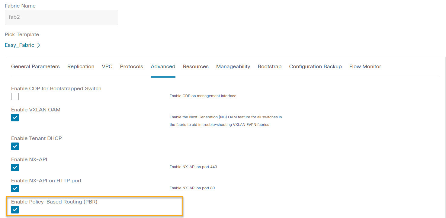
The Create Fabric window is displayed. Provide a Fabric Name and Pick a Template. Click Advanced. Select the Enable Policy-Based Routing (PBR) checkbox to enable routing of packets based on the specified policy.
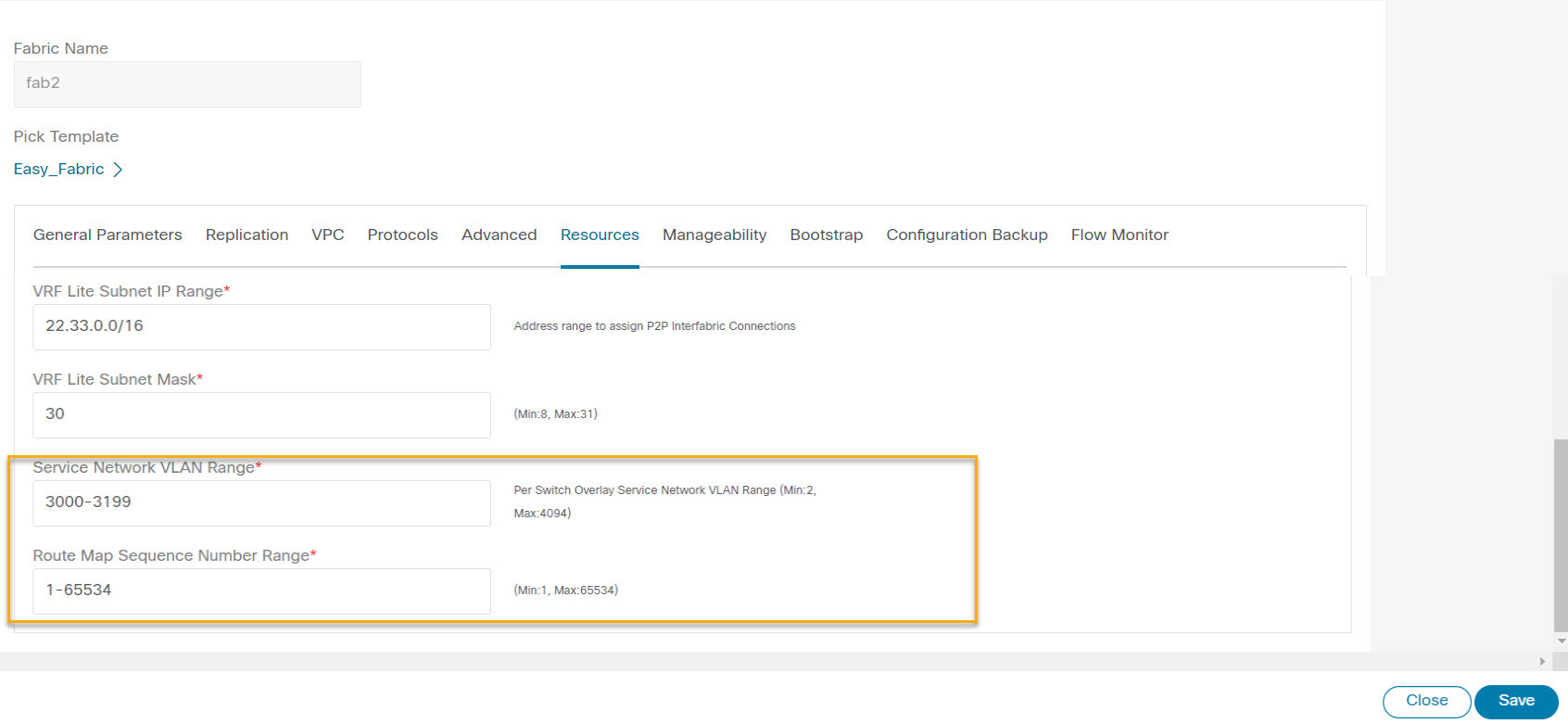
Click Resources. Specify a VLAN range in the Service Network VLAN Range field. This is a per switch overlay service network VLAN range. The minimum allowed value is 2 and the maximum allowed value is 4094. Also, specify a value for the Route Map Sequence Number Range field. The minimum allowed value is 1 and the maximum allowed value is 65534. Click Save to save the updated configuration.
Configuring L4-L7 Services
To launch the L4-L7 Services, or the Elastic Service, on the Cisco Nexus Dashboard Fabric Controller Web UI, choose LAN > Services.
You can also navigate to Services tab by one of the following below mentioned paths:

The services configuration procedure consists of the following steps:
Adding Service Node
You can navigate to Service Node tab by one of the following below mentioned paths:
To create service node, click . The Create New Service Node window is displayed.
The Create New Service Node window has three guided steps: Create New Service Node, Create Route Peering, and Create Service Policy.
The Create New Service Node window has two sections - Create Service Node and Switch Attachment, followed by a Link Template drop-down list. You can select service_link_trunk, service_link_port_channel_trunk and service_link_vpc from this drop-down list based on the specified attached switch interface type.
The fields in the Create New Service Node window are as given below. It is mandatory to fill the fields marked with an asterisk.
Create New Service Node
Service Node Name: Enter a name for the service node. The name can have alphanumeric, underscore, or dash characters.
Service Node Type: Select Firewall, Load Balancer, or Virtual Networking Function.
Form Factor: Select Physical or Virtual.
External Fabric: Specify the external fabric.
Service Node Interface: Specify the service node interface.
Attached Fabric: Select a fabric from the list.
Attached Switch: Select a switch or a switch pair from the list.
Attached Switch Interface: Select the interface from the list. In case the vPC pair is selected from the Attached Leaf Switch list, the vPC channel will be shown in the Attached Switch Interface list. Otherwise, the port-channel and interfaces with trunk mode are shown in the Attached Leaf Switch Interface list.
Link Template: Select the service_link_trunk, service_link_port_channel_trunk, or the service_link_vpc template. For more information on template fields, refer Templates.
A form is displayed depending on the template used. Update all the required fields in the form and click Save.
Creating Route Peering
You can navigate to Route Peering tab by one of the following below mentioned paths:
The fields that appear in the Create Route Peering window depend on the type of L4-L7 service node chosen in the Create New Service Node window. Depending on the type chosen (Firewall or Load Balancer or VNF), the types of deployments are Intra-Tenant Firewall, Inter-Tenant Firewall, One-Arm load balancer and Two-Arm load balancer, and One-Arm VNF.
 Note |
Deletion of service network is not allowed on the Networks tab of detail screen from path LAN > Fabrics, click Launch icon Network window. |

Inside Network
VRF: Specify the VRF.
Network Type: Select Inside Network.
Service Network: Specify the name of the service network.
VLAN ID: Specify the VLAN ID. Valid IDs range from 2 to 3967. Click Propose to retrieve a value from the pre-defined L4-L7 service network VLAN range pool.
Service Network Template: Select the Service_Network_Universal template from the drop-down list. For more information on the template fields, refer Templates.
Outside Network
VRF: Specify the VRF.
Network Type: Select Outside Network.
Service Network: Specify the name of the L4-L7 service network.
VLAN ID: Specify the VLAN ID. Valid IDs range from 2 to 3967. Click Propose to retrieve a value from the pre-defined L4-L7 service network VLAN range pool.
Service Network Template: Select the Service_Network_Universal template from the drop-down list. For more information on the template fields, refer Templates.
Next Hop Section
Next Hop IP Address: Specify the next-hop IP address. This is the IP/VIP of the service node used for traffic redirection.
Next Hop IP Address for Reverse Traffic: Specify the next-hop IP address for reverse traffic. This is the IP/VIP of the service node used for traffic redirection.
Example: Inter-Tenant Firewall Deployment
Peering Option - Static Peering, Inside Network Peering Template - service_static_route, Outside Network Peering Template - service_static_route
The fields in the Create Route Peering window for an Inter-Tenant Firewall deployment are as given below. It is mandatory to fill the fields marked with an asterisk.
Peering Name: Specify a name for the peering. The name can have alphanumeric, underscore, or dash characters.
Deployment: Select Inter-Tenant Firewall.
Peering Option: Select Static Peering or eBGP Dynamic Peering.
Inside Network
VRF: Select a VRF from the drop-down list..
Network Type: Select Inside Network.
Service Network: Provide a L4-L7 service network name.
VLAN ID: Specify the VLAN ID. Valid IDs range from 2 to 3967. Click Propose to retrieve a value from the pre-defined L4-L7 service network VLAN range pool.
Network ID: Specify the Network ID. Valid IDs range from to .
Service Network Template: Select the Service_Network_Universal template from the drop-down list. For more information on the template fields, refer Templates.
Peering Template - Select service_static_route or service_ebgp_route from the drop-down list. For more information on the template fields, refer Templates.
Outside Network
VRF: Select a VRF from the drop-down list..
Network Type: Select Outside Network.
Service Network: Provide a L4-L7 service network name.
VLAN ID: Specify the VLAN ID. Valid IDs range from 2 to 3967. Click Propose to retrieve a value from the predefined L4-L7 service network VLAN range pool.
Service Network Template: Select the Service_Network_Universal template from the drop-down list. For more information on the template fields, refer Templates.
Peering Template: Select service_static_route or service_ebgp_route from the drop-down list. For more information on the template fields, refer Templates.
Example: One-Arm Mode Load Balancer
The fields in the Create Route Peering window for a One-Arm Firewall deployment are as given below. It is mandatory to fill the fields marked with an asterisk.
Peering Name: Specify a name for the peering. The name can have alphanumeric, underscore, or dash characters.
Deployment: Select One-Arm F.
Peering Option: Select Static Peering or eBGP Dynamic Peering.
Inside Network
VRF: Select a VRF from the drop-down list..
Network Type: Select First Mode.
Service Network: Provide a L4-L7 service network name.
VLAN ID: Specify the VLAN ID. Valid IDs range from 2 to 3967. Click Propose to retrieve a value from the pre-defined L4-L7 service network VLAN range pool.
Service Network Template: Select the Service_Network_Universal template from the drop-down list. For more information on the template fields, refer Templates.
Peering Template: Select service_static_route or service_ebgp_route from the drop-down list. For more information on the template fields, refer Templates.
Next Hop IP Address for Reverse Traffic: Specify the next-hop IP address for reverse traffic.
Example: Two-Arm Mode Load Balancer
The fields in the Create Route Peering window for a Two-Arm Mode load balancer deployment are as given below. It is mandatory to fill the fields marked with an asterisk.
Peering Name: Specify a name for the peering. The name can have alphanumeric, underscore, or dash characters.
Deployment: Select Two-Arm Mode.
Peering Option: Select Static Peering or eBGP Dynamic Peering.
First Arm
VRF: Select a VRF from the drop-down list..
Network Type: Select First Arm.
Service Network: Provide a L4-L7 service network name.
VLAN ID: Specify the VLAN ID. Valid IDs range from 2 to 3967. Click Propose to retrieve a value from the pre-defined L4-L7 service network VLAN range pool.
Service Network Template: Select the Service_Network_Universal template from the drop-down list. For more information on the template fields, refer Templates.
Peering Template: Select service_static_route or service_ebgp_route from the drop-down list. For more information on the template fields, refer Templates.
Second Arm
VRF: Select a VRF from the drop-down list..
Network Type: Select Second Arm.
Service Network: Provide a L4-L7 service network name.
VLAN ID: Specify the VLAN ID. Valid IDs range from 2 to 3967. Click Propose to retrieve a value from the pre-defined L4-L7 service network VLAN range pool.
Service Network Template: Select the Service_Network_Universal template from the drop-down list. For more information on the template fields, refer Templates.
Next Hop Section
Next Hop IP Address for Reverse Traffic: Specify the next-hop IP address for reverse traffic.
Now, click Save. The Create Policy window is displayed.
Example: One-Arm Virtual Network Function
The fields in the Create Route Peering window for a One-Arm Mode Virtual Network Function deployment are as given below. It is mandatory to fill the fields marked with an asterisk.
Peering Name: Specify a name for the peering. The name can have alphanumeric, underscore, or dash characters.
Deployment: Select One-Arm Mode.
Peering Option: Select Static Peering or eBGP Dynamic Peering.
One Arm
VRF: Select a VRF from the drop-down list..
Network Type: Select One Arm.
Service Network: Provide a L4-L7 service network name.
VLAN ID: Specify the VLAN ID. Valid IDs range from 2 to 3967. Click Propose to retrieve a value from the predefined L4-L7 service network VLAN range pool.
Service Network Template: Select the Service_Network_Universal template from the drop-down list. For more information on the template fields, refer Templates.
IPv4 Gateway/Netmask: Specify the IPv4 gateway and netmask.
Peering Template: Select service_static_route or service_ebgp_route from the drop-down list. For more information on the template fields, refer Templates.
Next Hop IP Address for Reverse Traffic: Specify the next-hop IP address for reverse traffic.
Now, click Save. The Create Policy window is displayed.
Creating Service Policy
You can navigate to Service Policy tab by one of the following below mentioned paths:
The Create Service Policy window is displayed as given below.
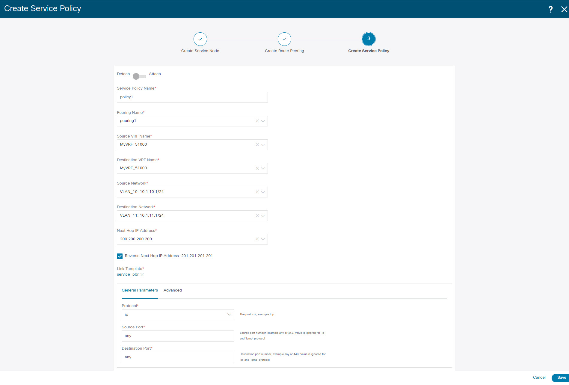
The fields in the Create Service Policy window are as given below. It is mandatory to fill the fields marked with an asterisk.
Service Policy Name: Specify a name for the policy.
Peering Name: Select the name of the route peering from the drop-down list.
Source VRF Name: Select a source VRF from the drop-down list.
Destination VRF Name: Select a destination VRF from the drop-down list.
Source Network: Select an IP address from the drop-down list.
Destination Network: Select a network from the drop-down list, or type in an arbitrary network with subnet info. The same is for destination network.
Next Hop IP Address: The next-hop IP address is displayed.
Reverse Next Hop IP Address - The reverse next-hop IP address is displayed. By default, the check box will be chosen.
Link Template : Select a template from the drop-down list. For more information on the template fields, refer Templates.
General Parameters
Protocol: Select a protocol from the drop-down list. The options are icmp, ip, tcp, and udp.
Source Port: Specify a source port number. In case the ip protocol is selected, this value is ignored.
Destination Port: Specify a destination port number. In case the ip protocol is selected, this value is ignored.
The Advanced tab allow you to customize the matched traffic redirection. For example, you can specify matched traffic to be redirected using PBR, or for matched traffic to bypass a firewall and use routing table rules instead, or you can specify that any matched traffic has to be dropped. You can choose to override the route map match sequence number for prioritization. You can also customize the ACL name, however ensure that the ACL name that you specify is unique and the same name is not used for another ACL. If you do not specify the route map match sequence number or ACL name, the sequence number will be auto-populated from the designated resource pool and the ACL name will be auto-generated based on 5-tuples. For more information on the fields in the Advanced tab, refer Templates.
Click Save. The service policy is created.
Note |
Deletion of any service network in Top-Down provisioning that is used by Services is not allowed. Deletion of any regular network that is used in a service policy is also not allowed. |
Templates
Service Node Link Templates
service_link_trunk
General Parameters tab
MTU: Specifies the MTU for the interface. By default, this is set to jumbo.
SPEED: Specifies the speed of the interface. By default, this is set to Auto. You can change it to different supported speeds as required.
Trunk Allowed Vlans: Specify 'none',' all', or VLAN ranges. By default, none is specified.
Enable BPDU Guard: Specify an option from the drop-down list. The available options are true, false, or no. By default, no is specified.
Enable Port Type Fast: Check this option to enable spanning tree edge port behavior. By default, this is enabled.
Enable Interface: Clear the check box to disable the interface. By default, the interface is enabled.
Advanced tab
Source Interface Description: Enter a description for the source interface.
Destination Interface Description: Enter a description for the destination interface.
Source Interface Freeform Config: Enter any addition CLI for the source interface.
Destination Interface Freeform Config: Enter any addition CLI for the destination interface.
service_link_port_channel_trunk
Port Channel Mode: Select a port channel mode from the drop-down list. By default, active is specified.
Enable BPDU Guard: Specify an option from the drop-down list. The available options are true, false, or no.
MTU: Specifies the MTU for the interface. By default, this is set to jumbo.
Trunk Allowed Vlans: Specify 'none',' all', or VLAN ranges. By default, none is specified.
Port Channel Description: Enter a description for the port channel.
Freeform Config: Specify the required freeform configuration CLIs.
Enable Port Type Fast: Check this option to enable spanning tree edge port behavior. By default, this is enabled.
Enable Port Channel: Check this option to enable the port channel. By default, this is enabled.
service_link_vpc
This template has no specifiable parameters.
Route Peering Service Network Template
Service_Network_Universal
General Parameters tab
IPv4 Gateway/Netmask: Specify the gateway IP address and mask of the service network.
IPv6 Gateway/Prefix: Specify the gateway IPv6 address and prefix of the service network.
Vlan Name: Specify a name for the VLAN.
Interface Description: Enter a description for the interface
Advanced tab
Routing Tag: Specify a routing tag. Valid values range from 0 to 4294967295.
Route Peering Templates
service_static_route
Enter the static routes in the Static Routes field. You can enter one static route per line.
service_ebgp_route
General Parameters tab
Neighbor IPv4: Specify the IPv4 address of the neighbor.
Loopback IP: Specify the IP address of the loopback.
Advanced tab
Neighbor IPv6: Specify the IPv6 address of the neighbor.
Loopback IPv6: Specify the IPv6 address of the loopback.
Route-Map TAG: Specify route-map tag that is associated with the interface ID.
Interface Description: Enter a description for the interface.
Local ASN: Specify a local ASN to override the system ASN.
Advertise Host Routes: Select this option to enable advertisement of /32 and /128 routes to edge routers.
Enable Interface: Clear this option to disable the interface. By default, the interface is enabled.
Service Policy Template
service_pbr
General Parameters tab
Protocol: Select a protocol from the drop-down list. The options are icmp, ip, tcp, and udp.
Source port: Specify a source port number. In case the ip protocol is selected, this value is ignored.
Destination port: Specify a destination port number. In case the ip protocol is selected, this value is ignored.
Advanced tab
Route Map Action: Select an action from the drop-down list. The options are permit or deny. If you select permit, the matched traffic is redirected based on the next-hop option and the defined policy. If you select deny, the traffic is routed based on the routing table rules.
Next Hop Option: Specify an option for the next-hop. The options are none, drop-on-fail, and drop.If you select none, the matched traffic is redirected based on the defined PBR rules. If you select drop-on-fail, the matched traffic is dropped if the specified next hop is not reachable. If you select drop, the matched traffic is dropped.
ACL Name: Specify a name for the generated access control list (ACL). If not specified, this is auto-generated.
ACL Name for reversed traffic: Specify a name for the ACL that is generated for reversed traffic. If not specified, this is auto-generated.
Route map match number: Specify a route map match number. A valid value ranges from 1 to 65535. If not specified, a route map match sequence number will be retrieved from the predefined resource pool. This number is associated with the name of the ACL.
Route map match number for reversed traffic: Specify a route map match number for reversed traffic. A valid value ranges from 1 to 65535. If not specified, a route map match sequence number will be retrieved from the predefined resource pool. This number is associated with the name of the ACL that has been generated for reversed traffic.
You can also customize the templates based on specific requirements.
Route Peering
UI Path: , double-click on required service name to view detailed window. Navigate to Route Peering tab.
Alternatively, you can choose LAN > Fabrics, click on Fabric detail view and on the Services to view Route Peering tab.
Route peering creates service networks. Nexus Dashboard Fabric Controller supports both static route and eBGP-based dynamic route peering options. After you specify the service network and select the peering policy for the tenant, Nexus Dashboard Fabric Controller automatically creates the service network under the specified tenant. Note that the terms, tenant and VRF, will be used interchangeably in this guide.
You cannot delete the service network. Deletion of service networks is handled automatically during the service route peering deletion process. There can be multiple route peerings defined per tenant/VRF.
To create Route Peering, refer to Creating Route Peering.
The following table describes the fields that appear on Route Peering window.
|
Field |
Description |
|---|---|
|
Service Network One |
|
|
Peering Name |
Specifies the peering name of service Doube-click on Peering Name, detailed window appears. For more information refer to Route Peering Details. |
|
Deployment |
Specifies the type of deployment. The deployment can be one of the following:
|
|
Peering Option |
Specifies the selected peering option |
|
Status |
Specifies the status of service |
|
Attachment Status |
Specifies the status of service, whether it is attached or detached |
|
VRF |
Specifies the name of VRF attached with the service node |
|
Network Name |
Specifies the name of network associated with service node |
|
Gateway IP |
Specifies the gateway IP address of the service node |
|
Service Network Two |
|
|
VRF |
Specifies the name of VRF attached with the service |
|
Network Name |
Specifies the name of network associated with service node |
|
Gateway IP |
Specifies the gateway IP address |
|
Next Hop IP |
Specifies the hop IP address associated with the service node |
|
Reverse Next Hop IP |
Specifies the reverse next hop IP address associated with the service node |
|
Next Hop IPv6 |
Specifies the next hop IPv6 address associated with the service node |
|
Reverse Next Hop IPv6 |
Specifies the reverse next hop IPv6 address associated with the service node |
|
Last Updated |
Specifies the last modification time and date for the service node |
The following table describes the action items, in the Actions drop-down list, that appears in the Route Peering window.
|
Action Item |
Description |
||
|---|---|---|---|
| Add |
Choose Add. The Create Route Peering window appears. Specify the required parameters and click Save. |
||
| Edit |
Choose required peering and click Edit. The Edit Route Peering window appears. Use the toggle to attach or detach the route peering. When the service policy is attached or enabled, the corresponding policies are applied to the VRF (tenant), source, and destination networks. Specify the required parameters and click Save. |
||
| Attach |
To attach a specific route peering to a switch, choose the required peering and click Attach.
|
||
| Detach |
To detach a specific route peering from a switch, choose the required peering and click Detach. |
||
| Preview |
To display the preview, choose the required peering and click Preview. A Preview Route Peering window is displayed. Select a specific switch, network, or VRF from the respective drop-down lists to display the route peerings for specific switches, networks, and VRFs. Click Close to close the window. |
||
| Deploy |
To deploy a route peering, choose required peering, click Deploy. A pop-up window appears for confirmation to deploy. Click Deploy. |
||
| Import |
To import route peering information as an Excel file, click Import. The Route Peering Import window appears. Click Browse, choose appropriate file, and then click Import to import information about the route peerings. |
||
| Export |
To export route peering information as an Excel file, click Export. The Route Peering Export window appears. Click Export to export information about the selected route peering. |
||
| Delete |
To delete the route peering, choose appropriate route peering, and click Delete. |
Route Peering Details
To view peering details window, navigate to Services, double-click on required service Name, Peering details window appears. You can view below tabs on the window:
-
Overview
-
Status Details
-
Route Peering
-
Service Policy
Overview
The Overivew tab displays Route Peering Summary with Inside and Outside Network details, Service Policies, and Service Node as cards.
Status Details
This tab provides a peak into the deployed configuration. Hover over the i icon next to the Status Details field in each row to display more information.
Service Policy
Refer to Service Policy.
Viewing Deployment History
This tab displays deployment history of the switches and networks that are involved in the route peering. This tab displays information such as the name of the network, VRF, and switch, status, status message, status details, and time of execution.
Service Policy
You can define service policies with any or arbitrary network and associate it with L3 routed interface on border switches. For more information, see PBR Support on WAN Interfaces of Border Switches. The L4-L7 service does not create any VRF or network other than the service networks that are defined during route peering. When you define the service policy between the created networks, the source and destination network can be a subnet, an individual IP address or the networks that are defined in the Services tab of fabric detail screen. Choose LAN >Fabric, click on Fabric detail view to view services tab. For intra-tenant firewall, one-arm and two-arm load balancer, the L4-L7 service in Nexus Dashboard Fabric Controller uses Policy-Based Routing (PBR) for service insertion. The inter-tenant firewall does not have a service policy. You only need to create a service node and route peering for inter-tenant firewall.
As the source and destination network can be attached or deployed independent of service policy deployment, the tenant/ VRF-related service policy configuration is only attached or pushed to the switch that is attached to the service node, and the source and destination network is updated with the service policy-related configuration. You can preview and confirm the generated configuration. By default, the service policy is defined but is not enabled or attached. You have to enable or attach the service policy to activate it.
The service configuration that is related to the source and destination network will be auto-processed when the source and destination networks are to be attached, or auto-updated in case the networks are already attached or deployed. By default, Nexus Dashboard Fabric Controller will collect statistics every 5 minutes and store it in the database for aggregation and analysis. By default, the statistics are stored for a maximum of 7 days.
The service insertion is effective only on the flows to be created. There is no impact on any existing flows. Deletion of a network is not allowed in case an enabled service policy is associated with that network.
The L4-L7 service integration is built on top of the easy fabric policy enforcement. Choose , to create a VXLAN EVPN fabric and then import Cisco Nexus 9000 Series switches into the fabric with predefined fabric policies.
To create service policy, refer to Creating Service Policy.
The following table describes the fields that appear on Route Peering window.
|
Field |
Description |
|---|---|
|
Policy Name |
Specifies the policy name of service Doube-click on Policy Name, detailed window appears. For more information refer to Service Policy Detail section. |
|
Route Peering |
Specifies the route peering name |
|
Status |
Specifies the status of service |
|
Attachment Status |
Specifies the status of service, whether it is attached or detached |
|
Source VRF |
Specifies the name of VRF attached with the service node |
|
Source Network |
Specifies the name of source network |
|
Destination VRF |
Specifies the name of destination VRF attached with the service node |
|
Destination Network |
Specifies the name of destination network |
|
Next Hop IP |
Specifies the hop IP address associated with the service node |
|
Reverse Next Hop IP |
Specifies the reverse next hop IP address associated with the service node |
|
Next Hop IPv6 |
Specifies the next hop IPv6 address associated with the service node |
|
Reverse Next Hop IPv6 |
Specifies the reverse next hop IPv6 address associated with the service node |
|
Reverse Enabled |
Specifes if reverse next-hop is enabled or not. |
|
Route Map Action |
The options are permit or deny. If you select permit, the matched traffic is redirected based on the next-hop option and the defined policy. If you select deny, the traffic is routed based on the routing table rules. |
|
Next Hop Option |
Specify an option for the next-hop. The options are none, drop-on-fail, and drop.If you select none, the matched traffic is redirected based on the defined PBR rules. If you select drop-on-fail, the matched traffic is dropped if the specified next hop is not reachable. If you select drop, the matched traffic is dropped. |
|
Last Updated |
Displays the time at which the service policy was last updated. |
The following table describes the action items, in the Actions drop-down list, that appears in the Route Peering window.
|
Action Item |
Description |
||
|---|---|---|---|
| Add |
Choose Add. The Create Service Policy window appears. Specify the required parameters and click Save. |
||
| Edit |
Choose required service policy and click Edit. The Edit Service Policy window appears. Use the toggle to attach or detach the service policy. When the service policy is attached or enabled, the corresponding policies are applied to the VRF (tenant), source, and destination networks. Specify the required parameters and click Save. |
||
| Attach |
To attach a specific service policy to a switch, choose the required policy and click Attach.
|
||
| Detach |
To detach a specific service policy from a switch, choose the required service policy and click Detach. |
||
| Preview |
To display the preview, choose the required peering and click Preview. A Preview Service Policy window is displayed. Select a specific switch, network, or VRF from the respective drop-down lists to display the service policy for specific switches, networks, and VRFs. Click Close to close the window. |
||
| Deploy |
To deploy a service policy, choose required service policy, click Deploy. A pop-up window appears for confirmation to deploy. Click Deploy. |
||
| Import |
To import service policy information as an Excel file, click Import. The Service Policy Import window appears. Click Browse, choose appropriate file, and then click Import to import information about the service policy. |
||
| Export |
To export route service policy information as an Excel file, click Export. The Service Policy Export window appears. Click Export to export information about the selected service policy. |
||
| Delete |
To delete the service policy, choose appropriate service policy, and click Delete. |
Service Policy Details
To view service policy window, navigate to Services, double-click on required service Name, service policy details window appears. You can view below tabs on the window:
-
Overview
-
Status Details
-
Route Peering
-
Service Policy
Overview
The Overivew tab displays Policy Summary, Service Node, and Route Peering with Inside and Outside Network as cards.
Status Details
This tab displays Resource Type, Fabric Name, Resource Name details associated with the selected service policy
Statistics
This tab displays statistical information about the configured service policies. Select a time range for which the statistics should be displayed from the Time Range drop-down box. You can select the date from the calendar displayed on the window and the time by clicking select time at the bottom right corner of the window. You can also display statistics from the last 15 minutes, 1 hour, 6 hours, 1 day, 1 week, and 1 month. Select the required time range and click Apply. Select a switch for which the statistics should be displayed from the Switch drop-down list. The statistics are then displayed for the selected switch in the specified time range.
Click Clear Stats to reset the statistics for a specific policy on all involved switches. If multiple policies are sharing the same route map, then the statistics of other policies are also impacted.
Viewing Deployment History
This tab displays deployment history of the switches and networks that are involved in the service policy. This tab displays information such as the name of the network, VRF, switch name, status, status message, status details, and time of execution.
Refreshing a Service Node
To refresh the list of service node that is displayed in the Service Nodes window, click the Refresh icon .
Viewing Audit History
To view audit history of the switches and networks that are involved in the selected service policy or route peering, click the Audit History tab in the Services window.
Audit Logs table in the Audit History window displays information about all the actions that have been performed:
|
Field |
Description |
|---|---|
|
User Name |
Specifies the user name of service node. |
|
User Role |
Specifies the user role name by whom latest action performed. |
|
Action Taken |
Specifies the latest action performed |
|
Entity |
Specifies the name of service node. |
|
Details |
Sepcifies the details of the service node |
|
Status |
Sepcifies the status of the service node |
|
Time |
Sepcifies the action time on that node |
|
More Info |
Click More Info to view detailed information of selected service node. |
-
Creation of service nodes, route peering, and service policies
-
Deletion of service nodes, route peering, and service policies
-
Update of service nodes, route peering, and service policies
-
Attachment and detachment of route peering, and service policies
-
Deployment of route peering and service policies
Audit logs are generated when the below actions are performed, these audit log is saved with the name of the user who has performed the action, the role of the user, the action taken, the entity on which the action was performed, details about the action, the status, and the time at which the action was performed.
To delete older audit reports, click , specify the maximum retained dates and confirm deletion. Note that only users with the admin role can delete audit log entries.
Importing Service Nodes
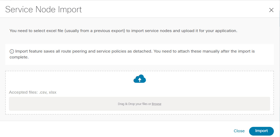
To import service nodes from an Excel file, click Actions > Import on the Service Nodes window. The Servie Node Import window appears.
Click Browser or drag and drop your file, and click Import button on the Service Node Import window to import information about the service nodes.
You can also restore the service node level data by clicking Actions > Import to import data about the service nodes from an excel file.
Exporting Service Nodes
You can back up data at the Service node level by clicking Actions > Export option to export data about the service nodes to an excel file. Data regarding all the service nodes, the respective route peerings, and service policy, is exported.
You can also export data for a specific Service node by selecting the node and clicking Actions > Export. A confirmation window appears, click Export.
Editing a Service Node
Procedure
|
Step 1 |
Choose a service node from the table and click Actions > Edit. |
|
Step 2 |
The Edit Service Node window is displayed. Make the required changes and click Save. |
Deleting a Service Node
Procedure
|
Select a service node from the table and click Actions > Delete.
|
 Feedback