Nodes and Sites
Both node and site are Cisco Crosswork Planning terminology.
-
Node—A device in the network, which can be one of three types: physical, PSN (pseudonode), or Virtual. The Type property distinguishes whether the node represents a real device or an abstraction, such as a single node representing a number of edge nodes connected in the same way to the network. A physical node is a Layer 3 device, or router. Physical and virtual nodes behave in the same way within Cisco Crosswork Planning. A pseudo-node (PSN) is typically used to represent a Layer 2 device or a LAN.
Nodes can reside both inside and outside of sites. The external arrangement could be useful for small networks where routers are not geographically dispersed.
-
Site—A collection of nodes and/or other sites that potentially form a hierarchy of sites. Any site that contains other sites is called the parent site.
Both nodes and sites have simulated traffic, while nodes also have measured traffic.
-
Nodes are shown as blue router icons (
 ). The border color is an indication of traffic sourced from and destined to the node. A light blue outline indicates that
the node is selected. For more information, click the
  icon in the network plot.
-
Sites are shown as blue circles (
 ). The border color indicates the traffic utilization of all the nodes and circuits inside the site, including all nested
nodes and circuits. A light blue outline indicates that the site is selected . The number inside the circle indicates the
number of nodes in the site. For more information, click the
  icon in the network plot.
Note that sites can contain L3 nodes. Empty sites and sites containing L3 nodes appear in the L3 view.
Parent Sites and Contained Objects
Unless a site is empty, there is a hierarchy of the sites and nodes that a site contains. A site can be both a parent and a child site. If a site contains another site, it is a parent site. Any nodes, sites, or circuits within a parent site are contained (nested) objects. The contained nodes and sites are also called children. Often the child nodes and sites are geographically co-located. For example, a site might be a PoP where the routers reside.
-
The site’s Parent site property defines whether it is nested within another site. If it is empty, the site is not nested.
-
In the network plot, the parent site shows all egress inter-site interfaces of all nodes contained within it, no matter how deeply the nodes are nested. Similarly, this is true for each child site plot within it.
-
Selecting a site from the network plot does not select the sites or nodes under it.
Delete Sites
Selecting a site from the network plot does not select the sites or nodes under it except when deleting the site. In this case, all objects within a site are selected for deletion. However, in the confirmation that appears, you have the option to keep the contained sites and nodes. If you do, then the objects that are contained directly within it are moved to be on the same level as the site that is removed. The other, more deeply nested objects maintain their parent relationships.
PSN Nodes
Cisco Crosswork Planning network models can contain nodes of with a Type property of “psn”. These nodes represent pseudonodes (PSNs), which are used to model LANs or switches that connect more than two routers. They are used in two situations: for IGP modeling and BGP peer modeling.
In an IGP network, a LAN interconnecting multiple routers is represented by a PSN node, with circuits connected to each of the nodes representing the interconnected routers. Both OSPF and IS-IS have a built-in system whereby one of the routers on that LAN is the designated router (DR) for OSPF or the designated intermediate system (DIS) for IS-IS. The PSN node is named after this designated router. Cisco Crosswork Planning creates nodes with a property Type of PSN automatically during IGP discovery.
When BGP peers are discovered, Cisco Crosswork Planning might find that a router is connected to multiple peers using a single interface. This is typical at switched Internet Exchange Points (IXPs). Cisco Crosswork Planning then creates a node with a property Type of PSN, and connects all the peers to it, each on a different interface.
Few points to consider when working with nodes that have PSN as a Type property are:
-
Two PSNs cannot be connected by a circuit.
-
If a PSN node is created by Cisco Crosswork Planning, “psn” is prepended to the designated router’s node name.
-
When creating demand meshes, Cisco Crosswork Planning does not create demands with nodes of Type psn as sources or destinations. This is possible in manual demand creation, but not recommended. Cisco Crosswork Planning sets the IGP metric for all egress interfaces from a node of Type psn to zero. This ensures that the presence of a PSN in a route does not add to the IGP length of the path.
Create Nodes and Sites
Create Nodes
To create nodes, follow the steps in Create Objects, where Object is Node.
These are some of the frequently used fields and their descriptions.
-
Name—Required unique name for the node.
-
IP address—Often the loopback address used for the router ID.
-
Site—Name of the site in which the node exists. If left empty, the node resides in the network plot. This offers a convenient way to create a site while creating the node, move nodes from one site to another, or remove nodes from a site so it stands alone in the network plot.
-
AS—Name of the AS in which this node resides, which identifies its routing policy. This can be left empty if no BGP is being simulated.
-
BGP ID—IP address that is used for BGP.
-
Function—Identifies whether this is a Core or Edge node.
-
Type—The node type, which is physical, PSN, or virtual. Because a PSN node represents a Layer 2 device or a LAN, interfaces on a PSN must all have their IGP metrics set to zero, and two PSN nodes cannot be directly connected to one another. If you change a node type to PSN, Cisco Crosswork Planning automatically changes the IGP metrics on its associated interfaces to zero.
-
Longitude and Latitude—Geographic location of the node within the network plot. These values are relevant when using geographic backgrounds.
Create Sites
To create sites, follow the steps in Create Objects, where Object is Site.
These are some of the frequently used fields and their descriptions.
-
Name—Unique name for the site.
-
Display name—Site name that appears in the plot. If this field is empty, the Name entry is used.
-
Parent site—The site that immediately contains this site. If empty, the site is not contained within another one.
-
Location—Select the location from the list of cities. To automatically place a site in its correct geographic location and update the Longitude and Latitude fields, enter the airport code and press Enter.
-
Longitude and Latitude—Geographic location of the site within the network plot. These values are relevant when using geographic backgrounds.
Merge Nodes
Real network topologies often have a number of nodes, typically edge nodes, connected to the network in the same way. For example, they might all be connected to the same core node or pair of core nodes. For planning and design of the network core, it is often desirable to merge these physical nodes into a single virtual node, which simplifies the plan and accelerates the calculations and simulations performed. Note that merging nodes changes the plan itself, not just the visual representation.

The name of a newly merged node can be based on the site name, selected node name (base node), or have a new user-specified name. The node merge effects are as follows:
-
Reattach circuits from other nodes to the base node.
-
Move demands to or from other nodes to the base node.
-
Move LSPs to or from other nodes to the base node.
-
Set base node traffic measurements to the sum of measurements of the selected nodes.
-
Delete other nodes.
Follow these steps to merge nodes.
Procedure
|
Step 1 |
Open the plan file (see Open Plan Files). The plan file opens in the Network Design page. |
|
Step 2 |
From the toolbar, choose Actions > Initializers > Merge nodes. |
|
Step 3 |
Select the nodes that you want to merge in the Merge Nodes wizard. If you do not select any nodes, Cisco Crosswork Planning merges all nodes. |
|
Step 4 |
Click Next. |
|
Step 5 |
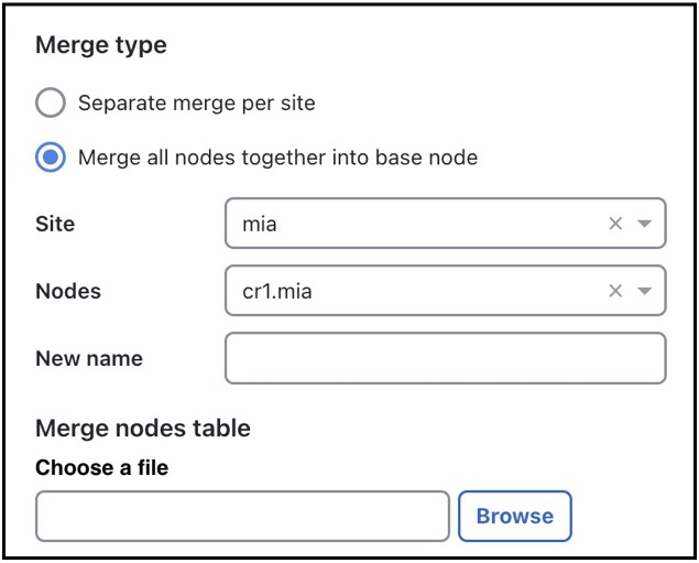
Select whether to merge the nodes per site or merge them into one node.
|
|
Step 6 |
Click Next. |
|
Step 7 |
Preview the list of effects of node merge. If these are acceptable, then click Merge. |


 Feedback