Internal Components
 Note |
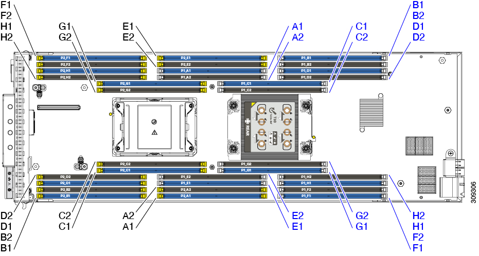
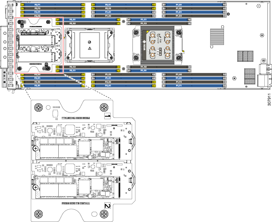
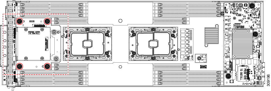
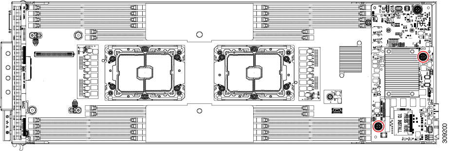
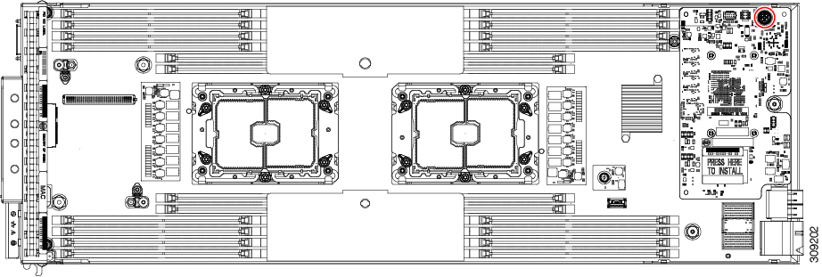
The CPUs on the Cisco UCS B200 M6 blade server are in opposite locations compared to previous generations. On the UCS B200 M6 blade server, CPU 1 is at the rear of the blade (the side nearest the internal connectors) and CPU 2 is at the front of the blade (the side nearest the faceplate and external ports and connectors). |

|
1 |
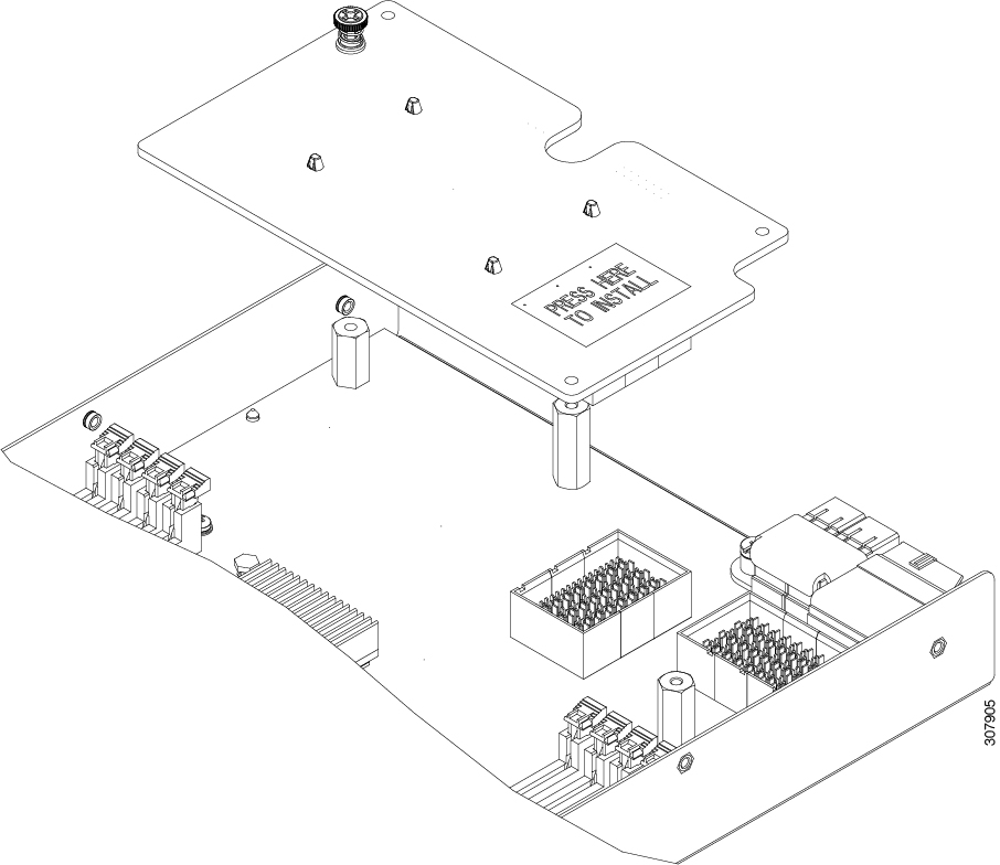
Front mezzanine connector |
2 |
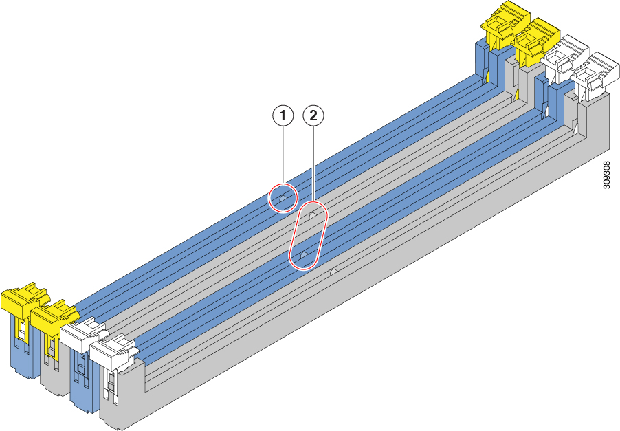
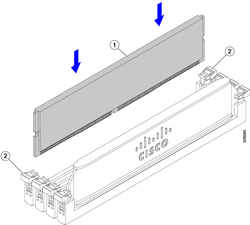
DIMM slots DIMMs are secured by white or yellow latches. White latches indicate the memory is connected to CPU 1. Yellow latches indicate the memory is connected to CPU 2. |
|
3 |
CPU socket 1 (Populated) CPU 1 connects to DIMMs with a white DIMM latch. This CPU socket must always be populated. If your server will run with only one CPU, the CPU must be installed in this socket. |
4 |
CPU socket 2 (Unpopulated) CPU 2 connects to DIMMs with a yellow DIMM latch. This CPU socket is populated in a normal, dual-CPU deployment. If your server will run with only one CPU, the CPU must be installed CPU socket 1. |
|
5 |
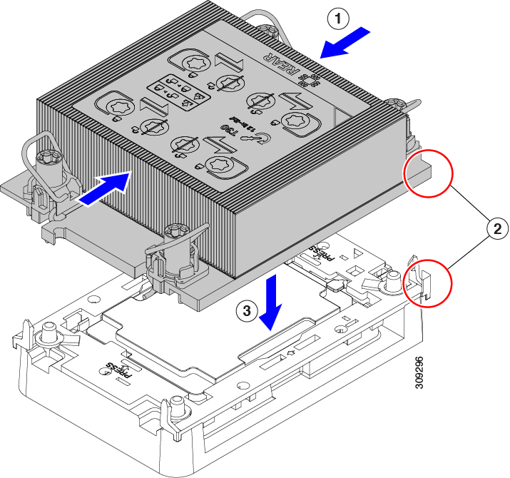
CPU heatsink install guide pins |
6 |
mLOM connector |
|
7 |
Rear mezzanine connector |
























 )
)
 )
)
 )
)
 )
)
 Feedback