Power Supply Modules Overview
The switch operates with either one or two active power supply modules. A switch that is part of a StackPower stack operates with power that is supplied by other stack switches. Two power supply modules can be powered up from two different phases. All power supply modules have internal fans.
You can either use two power supply modules or one module and a blank cover. If only one power supply module is ordered, a blank cover is provided for the second power supply slot. The blank cover plates are either pre-installed or shipped as an accessory, and must be installed by the customers.
The following table describes the supported internal power supply modules. It lists the Platinum certified power supply modules and the default modules that are shipped with the switch. In a switch, a mix of Platinum certified and non-Platinum certified power supply modules is supported.
|
Switch Series |
Supported Power Supply Modules |
Description |
|---|---|---|
|
C9300 Series Switches |
PWR-C1-350WAC |
350 W AC power supply module |
|
PWR-C1-715WAC |
715 W AC power supply module |
|
|
PWR-C1-1100WAC |
1100 W AC power supply module |
|
|
PWR-C1-715WAC-P |
715 W AC Platinum certified power supply module |
|
|
PWR-C1-1100WAC-P |
1100 W AC Platinum certified power supply module |
|
|
PWR-C1-1900WAC-P |
1900 W AC Platinum certified power supply module |
|
|
PWR-C1-1900WHV-T |
1900W DC power supply module |
|
|
PWR-C1-715WDC |
715 W DC power supply module |
|
|
C9300L Series Switches |
PWR-C1-350WAC |
350 W AC power supply module |
|
PWR-C1-715WAC |
715 W AC power supply module |
|
|
PWR-C1-715WAC-P |
715 W AC Platinum certified power supply module |
|
|
PWR-C1-1100WAC-P |
1100 W AC Platinum certified power supply module |
|
|
PWR-C1-1900WAC-P |
1900 W AC Platinum certified power supply module |
|
|
PWR-C1-715WDC |
715 W DC power supply module |
|
|
C9300LM Series Switches |
PWR-C6-600WAC |
600 W AC Platinum certified power supply module |
|
PWR-C6-1KWAC |
1000 W AC Platinum certified power supply module |
|
|
C9300X Series Switches |
PWR-C1-350WAC-P |
350 W AC Platinum certified power supply module |
|
PWR-C1-715WAC-P |
715 W AC Platinum certified power supply module |
|
|
PWR-C1-715WDC |
715 W DC power supply module |
|
|
PWR-C1-1100WAC-P |
1100 W AC Platinum certified power supply module |
|
|
PWR-C1-1900WAC-P |
1900 W AC Platinum certified power supply module |
 Note |
|
For information on available PoE, PoE+, and Cisco UPOE/UPOE+ requirements, see these sections the Power Supply Modules.
The 350 W and 715 W AC power supply modules are autoranging units that support input voltages from 100 through 240 VAC. The 1100W power supply module is an autoranging unit that supports input voltages from 115 through 240 VAC.
Each AC power supply module has a power cord for connection to an AC power outlet. To view the list of available AC power cords, see AC Power Cord Specifications.
The following illustrations show the power supply modules.

|
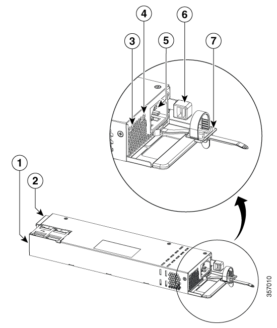
1 |
1100 W AC power supply module |
5 |
Release latch |
|
2 |
AC OK LED |
6 |
Power cord retainer |
|
3 |
PS OK LED |
7 |
Keying feature |
|
4 |
AC power cord connector |
- |
- |
|
1 |
1900 W AC power supply module |
5 |
AC power cord connector |
|
2 |
Keying feature |
6 |
Release latch |
|
3 |
AC OK LED |
7 |
Power cord retainer |
|
4 |
PS OK LED |
|
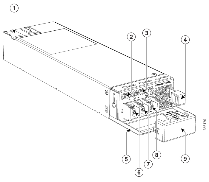
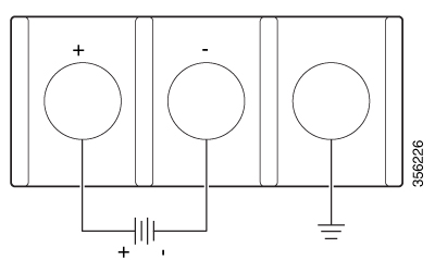
1 |
715 W DC power supply module |
6 |
Input power terminal (positive polarity) |
|
2 |
DC OK LED |
7 |
Input power terminal (negative polarity) |
|
3 |
PS OK LED |
8 |
Grounding terminal |
|
4 |
Release latch |
9 |
Terminal block safety cover |
|
5 |
Extraction handle |
- |
- |
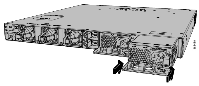
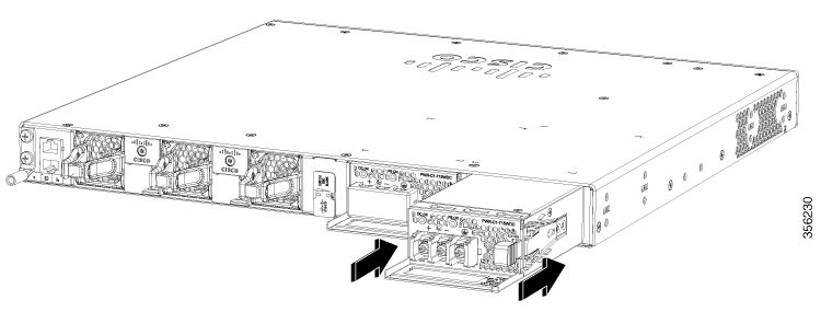
If no power supply is installed in a power supply slot, install a power supply slot cover.

|
1 |
Release handles |
2 |
Retainer clips |
|
AC or DC OK |
Description |
PS OK |
Description |
|---|---|---|---|
|
Off |
No AC or DC input power. |
Off |
Output is disabled, or input is outside operating range (LED is off). |
|
Green |
AC or DC input power present. |
Green |
Power output to switch active. |
|
Red |
Output has failed. |


 Feedback