Prepare for Installation

This chapter provides preinstallation information, such as recommendations and requirements that must be met before installing your platform. Before you begin, inspect all items for shipping damage. If anything appears to be damaged or if you encounter problems installing or configuring your platform, contact customer service.

Warning


Statement 7003—Shielded Cable Requirements for Intrabuilding Lightning Surge

The intrabuilding port(s) of the equipment or subassembly must use shielded intrabuilding cabling/wiring that is grounded at both ends.

The following port(s) are considered intrabuilding ports on this equipment:

Gigabit Ethernet WAN port


Warning


Statement 7005—Intrabuilding Lightning Surge and AC Power Fault

The intrabuilding port(s) of the equipment or subassembly is suitable for connection to intrabuilding or unexposed wiring or cabling only. The intrabuilding port(s) of the equipment or subassembly MUST NOT be metallically connected to interfaces that connect to the OSP or its wiring for more than 6 meters (approximately 20 feet). These interfaces are designed for use as intrabuilding interfaces only (Type 2, 4, or 4a ports as described in GR-1089) and require isolation from the exposed OSP cabling. The addition of primary protectors is not sufficient protection in order to connect these interfaces metallically to an OSP wiring system.

The following ports are considered intrabuilding ports on the equipment:

Gigabit Ethernet WAN port


Note


Statement 7018—System Recover Time

The equipment is designed to boot up in less than 30 minutes provided the neighboring devices are fully operational.


Note


Statement 7004—Special Accessories Required to Comply with GR-1089 Emission and Immunity Requirements

To comply with the emission and immunity requirements of GR-1089, shielded cables are required for the following ports:

Gigabit Ethernet WAN port


Note


Statement 7013—Equipment Grounding Systems—Common Bonding Network (CBN)

This equipment is suitable for installations using the CBN.


Note


Statement 8015—Installation Location Network Telecommunications Facilities

This equipment is suitable for installation in network telecommunications facilities.


Standard Warning Statements

This section describes the warning definition and then lists core safety warnings grouped by topic.


Warning


Statement 1071—Warning Definition

IMPORTANT SAFETY INSTRUCTIONS

Before you work on any equipment, be aware of the hazards involved with electrical circuitry and be familiar with standard practices for preventing accidents. Read the installation instructions before using, installing, or connecting the system to the power source. Use the statement number provided at the end of each warning statement to locate its translation in the translated safety warnings for this device.

SAVE THESE INSTRUCTIONS


Gigabit Ethernet WAN port

General Safety Warnings


Warning


Statement 1004—Installation Instructions

Read the installation instructions before using, installing, or connecting the system to the power source.


Warning


Statement 1030—Equipment Installation

Only trained and qualified personnel should be allowed to install, replace, or service this equipment.


Warning


Statement 9001—Product Disposal

Ultimate disposal of this product should be handled according to all national laws and regulations.


Warning


Statement 1074—Comply with Local and National Electrical Codes

To reduce risk of electric shock or fire, installation of the equipment must comply with local and national electrical codes.


Warning


Statement 1028—More Than One Power Supply

This unit might have more than one power supply connection. To reduce risk of electric shock, remove all connections to de-energize the unit.


Warning


Statement 1017—Restricted Area

This unit is intended for installation in restricted access areas. Only skilled, instructed, or qualified personnel can access a restricted access area.


Warning


Statement 1025—Use Copper Conductors Only

To reduce risk of fire, use copper conductors only.


Warning


Statement 1024—Ground Conductor

This equipment must be grounded. To reduce the risk of electric shock, never defeat the ground conductor or operate the equipment in the absence of a suitably installed ground conductor. Contact the appropriate electrical inspection authority or an electrician if you are uncertain that suitable grounding is available.


Warning


Statement 1034—Backplane Voltage

Hazardous voltage or energy is present on the backplane when the system is operating. Use caution when servicing.


Warning


Statement 1008—Class 1 Laser Product

This product is a Class 1 laser product.


Warning


Statement 1027—Class 1 LED Product

This is a Class 1 LED product.


Warning


Statement 1055—Class 1/1M Laser

Invisible laser radiation is present. Do not expose to users of telescopic optics. This applies to Class 1/1M laser products.
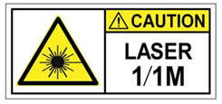


Warning


Statement 1056—Unterminated Fiber Cable

Invisible laser radiation may be emitted from the end of the unterminated fiber cable or connector. Do not view directly with optical instruments. Viewing the laser output with certain optical instruments, for example, eye loupes, magnifiers, and microscopes, within a distance of 100 mm, may pose an eye hazard.


Warning


Statement 1032—Lifting the Chassis

To prevent personal injury or damage to the chassis, never attempt to lift or tilt the chassis using the handles on modules, such as power supplies, fans, or cards. These types of handles are not designed to support the weight of the unit.


Warning


Statement 1047—Overheating Prevention

To reduce the risk of fire or bodily injury, do not operate the unit in an area that exceeds the maximum recommended ambient temperature of:


Note


The Cisco Catalyst 8500L-8S4X Edge Platform can reliably operate up to 55C for temporary durations per NEBS.


Warning


Statement 1022—Disconnect Device

To reduce risk of electric shock and fire, a readily accessible two-poled disconnect device must be incorporated in the fixed wiring.


Warning


Statement 1029—Blank Faceplates and Cover Panels

Blank faceplates and cover panels serve three important functions: they reduce the risk of electric shock and fire, they contain electromagnetic interference (EMI) that might disrupt other equipment, and they direct the flow of cooling air through the chassis. Do not operate the system unless all cards, faceplates, front covers, and rear covers are in place.


Warning


Statement 1030—Equipment Installation

Only trained and qualified personnel should be allowed to install, replace, or service this equipment.


Warning


Statement 1026—WAN Port Static Shock

Hazardous network voltages may be present in interface ports regardless of whether power to the unit is OFF or ON. To avoid electric shock, before servicing, disconnect cables from the following ports:


Warning


Statement 1035—Proximity to Water

Do not use this product near water, for example, near a bathtub, wash bowl, kitchen sink, laundry tub, in a wet basement, or near a swimming pool.


Warning


Statement 1073—No User-Serviceable Parts

There are no serviceable parts inside. To avoid risk of electric shock, do not open.


Warning


Statement 445—Connect the Chassis to Earth Ground

To reduce the risk of electric shock, connect the chassis of this equipment to permanent earth ground during normal use.


Warning


Statement 1086—Power Terminals, Replace Cover

Hazardous voltage or energy may be present on power terminals. To reduce the risk of electric shock, always replace the cover when terminals are not in service. Be sure uninsulated conductors are not accessible when the cover is in place.


Safety Recommendations

Follow these guidelines to ensure general safety:

  • Never attempt to lift an object that might be too heavy for you to lift by yourself.
  • Keep the chassis area clear and dust-free during and after installation.
  • If you remove the chassis cover, place it in a safe place.
  • Keep tools and chassis components away from walk areas.
  • Do not wear loose clothing that may get caught in the chassis. Fasten any tie or scarf and roll up sleeves.
  • Wear safety glasses when working under conditions that might be hazardous to your eyes.
  • Do not perform any action that may create a hazard to people or makes equipment unsafe.

Safety with Electricity


Warning


This unit might have more than one power supply connection. All connections must be removed to de-energize the unit. Statement 1028


Warning


Installation Instructions

Read the installation instructions before using, installing or connecting the system to the power source. Statement 1004


Warning


Blank Faceplates and Cover Panels

Blank faceplates and cover panels serve three important functions: they reduce the risk of electric shock and fire; they contain electromagnetic interference (EMI) that might disrupt other equipment; and they direct the flow of cooling air through the chassis. Do not operate the system unless all cards, faceplates, front covers, and rear covers are in place. Statement 1029


Follow these guidelines when working on equipment powered by electricity:

  • Locate the emergency power-off switch in the room in which you are working. If an electrical accident occurs, you can quickly turn off the power.

  • Disconnect all power before doing the following:

    • Installing or removing a chassis

    • Working near power supplies

  • Look carefully for possible hazards in your work area, such as moist floors, ungrounded power extension cables, frayed power cords, and missing safety grounds.

  • Do not work alone if hazardous conditions exist

  • Never assume that power is disconnected from a circuit. Always check

  • Never open the enclosure of the internal power supply

  • If an electrical accident occurs to another person, proceed as follows:

    • Use caution; do not become a victim yourself

    • Turn off power to the device

    • If possible, send another person to get medical aid. Otherwise, assess the condition of the victim and then call for help

    • Determine if the person needs rescue breathing or external cardiac compressions; then take appropriate action

Prevent Electrostatic Discharge Damage

Electrostatic discharge (ESD) can damage equipment and impair electrical circuitry. It can occur if electronic printed circuit cards are improperly handled and can cause complete or intermittent failures. Always follow these ESD prevention procedures when removing and replacing modules:

  • Ensure that the router chassis is electrically connected to the ground.
  • Wear an ESD-preventive wrist strap, ensuring that it makes good skin contact. Connect the clip to an unpainted surface of the chassis frame to channel unwanted ESD voltages safely to ground. To guard against ESD damage and shocks, the wrist strap and cord must operate effectively.
  • If no wrist strap is available, ground yourself by touching a metal part of the chassis.

Caution


For the safety of your equipment, periodically check the resistance value of the anti-static strap. It should be between 1 and 10 megohms (Mohm).


General Site Requirements

This section describes the requirements your site must meet for the safe installation and operation of your router. Ensure that the site is properly prepared before beginning installation. If you are experiencing shutdowns or unusually high errors with your existing equipment, the guidelines provided in this section can also help you isolate the cause of failures and prevent future problems.

General Precautions

Observe the following general precautions when using and working with your Cisco Catalyst 8500L-8S4X Edge Platform:

  • Keep your system components away from radiators and heat sources, and do not block cooling vents.

  • Do not spill food or liquids on your system components, and never operate the product in a wet environment.

  • Do not push any objects into the openings of your system components. Doing that can cause fire or electric shock by shorting out interior components.

  • Position system cables and power supply cables carefully. Route system cables and the power supply cable and plug so that they cannot be stepped on or tripped over. Be sure that nothing else rests on your system component cables or power cable.

  • Do not modify power cables or plugs. Consult a licensed electrician or your power company for electrical modifications at your site. Always follow your local and national wiring rules.

  • If you turn off your system, wait at least 30 seconds before turning it on again to avoid system component damage.

Site Selection Guidelines

Cisco Catalyst 8500L-8S4X Edge Platform require specific environmental operating conditions. Temperature, humidity, altitude, and vibration can affect the performance and reliability of the router. The following sections provide specific information to help you plan for the proper operating environment.

Site Environmental Requirements

Environmental monitoring in the router protects the system and components from damage caused by excessive voltage and temperature conditions. To ensure normal operation and avoid unnecessary maintenance, plan and prepare your site configuration before installation. After installation, ensure the site maintains the required environmental characteristics.

Table 1. Router Environmental Tolerances

Environmental Characteristic

Minimum

Maximum

Steady State Operating

0° C

40° C

40° C at 10,000 feet

Short Term (per NEBS GR-63-CORE)

-5° C

55° C at 6,000 feet

Storage

–40° C

+70° C

Humidity operating (noncondensing)

10%

90%

Humidity nonoperating (noncondensing)

5%

95%

Altitude operating: over allowable temperature range (0 to 40° C)

–500 feet

13,000 feet

Altitude, nonoperating: over allowable temperature range

–500 feet

16,000 feet

Thermal shock non-operating.

–40° C

+70° C

Physical Characteristics

Be familiar with the physical characteristics of the Cisco Catalyst 8500L-8S4X Edge Platform to assist you in placing the system in the proper location.

For more information on the physical characteristics of Cisco Catalyst 8500L-8S4X Edge Platform, refer to the datasheet for the Cisco Catalyst 8500L-8S4X Edge Platform.

Rack Requirements

Some Cisco routers include brackets for use with a 19-inch rack or, if specified in your order, optional wider brackets for use with a 23-inch rack.

The following information can help you plan your equipment rack configuration:

  • Allow clearance around the rack for maintenance.

  • Enclosed racks must have adequate ventilation. Ensure that the rack is not congested, because each router generates heat. An enclosed rack should have louvered sides and a fan to provide cooling air. Heat generated by equipment at the bottom of the rack can be drawn upward into the intake ports of the equipment above it.

  • When mounting a chassis in an open rack, ensure that the rack frame does not block the intake or exhaust ports. If the chassis is installed on slides, check the position of the chassis when it is seated in the rack.

Router Environmental Requirements

Cisco Catalyst 8500L-8S4X Edge Platform should be installed in a rack. The location of your router and the layout of your equipment rack or wiring room are extremely important considerations for proper operation. Equipment placed too close together, inadequate ventilation, and inaccessible panels can cause malfunctions and shutdowns, and can make maintenance difficult. Plan for access to both front and rear panels of the router.

When planning your site layout and equipment locations, refer to the General Site Requirements section. If you are currently experiencing shutdowns or an unusually high number of errors with your existing equipment, these precautions and recommendations may help you to isolate the cause of failure and prevent future problems.

  • Ensure that the room where your router operates has adequate air circulation. Electrical equipment generates heat. Without adequate air circulation, ambient air temperature may not cool equipment to acceptable operating temperatures.

  • Always follow the ESD-prevention procedures to avoid damage to equipment. Damage from static discharge can cause immediate or intermittent equipment failure.

  • Ensure that the chassis cover and module rear panels are secure. All empty network module slots, interface card slots, and power supply bays must have filler panels installed. The chassis is designed to allow cooling air to flow within it, through specially designed cooling slots. A chassis with uncovered openings permits air leaks, which may interrupt and reduce the flow of air across internal components.

  • Baffles can help to isolate exhaust air from intake air. Baffles also help to draw cooling air through the chassis. The best placement of the baffles depends on the airflow patterns in the rack. You can find the best placement by experimenting with different configurations.

  • If equipment installed in a rack (particularly in an enclosed rack) fails, try operating the equipment individually. Power off other equipment in the rack (and in adjacent racks) to allow the router under test maximum cooling air and clean power.

Power Guidelines and Requirements

Check the power at your site to ensure that you are receiving “clean” power (free of spikes and noise). Install a power conditioner if necessary.

The Cisco Catalyst 8500L-8S4X Edge Platform has specific power and electrical wiring requirements. Adhering to these requirements ensures reliable operation of the system. Follow these precautions and recommendations when planning your site for the Cisco Catalyst 8500L-8S4X Edge Platform:

  • The Cisco Catalyst 8500L-8S4X Edge Platform is always provided with a second, identical power supply to ensure that power to the chassis continues uninterrupted if one power supply fails or input power on one line fails.

  • In systems configured with the redundant power option, each of the two power supplies should be connected to a separate input power source. If you fail to do this, your system might be susceptible to total power failure due to a fault in the external wiring or a tripped circuit breaker

  • To prevent a loss of input power, be sure the total maximum load on each circuit supplying the power supplies is within the current ratings of the wiring and breakers

  • Provide proper grounding to avoid personal injury and damage to the equipment due to lightning striking power lines or due to power surges. The chassis ground must be attached to a central office or other interior ground system.

For additional information please refer to the Cisco Catalyst 8500L-8S4X Edge Platform datasheet.

Each Cisco Catalyst 8500L-8S4X Edge Platform requires a dedicated electrical circuit. If you equip it with dual-power feeds, you must provide a separate circuit for each power supply to avoid compromising the power redundancy feature.

The Cisco Catalyst 8500L-8S4X Edge Platform can be powered by a DC or AC source. Ensure that equipment grounding is present and observe power-strip ratings. Make sure that the total ampere rating of all the products plugged into the power strip does not exceed 80 percent of the rating.

For more information on the power supply system rating requirements for the Cisco Catalyst 8500L-8S4X Edge Platform, see Power Supplies section.

Network Cabling Specifications

The following sections describe the cables required to install your Cisco Catalyst 8500L-8S4X Edge Platform:

Console Port Considerations

This device includes an asynchronous serial console port. You access to the device locally using a console terminal connected to the console port. This section discusses important cabling information that you must consider before connecting the device to a console terminal.

The Cisco Catalyst 8500L-8S4X Edge Platform provides one console port to connect a terminal or computer for local console access.

The console port has a RJ-45 connector, supports RJ-232 asynchronous data, and has distance recommendations specified in the IEEE RS-232 standard.

EIA/TIA-232

Depending on the cable and the adapter used, this port appears as a DTE or DCE device at the end of the cable.

The default parameters for the console port are 9600 baud, 8 data bits, 1 stop bit, and no parity. The console port does not support hardware flow control.

USB Serial Console

The USB serial console port connects directly to the USB connector of a PC. The console port does use an USB Type A to 5-pin micro USB Type-B throughout cable to control the hardware flow. The USB Console supports full speed (12Mb/s) operation.


Note


  • Always use shielded USB cables with a properly terminated shield. The USB serial console interface cable must not exceed 3 meters in length.

  • Only one console port can be active at a time. When a cable is plugged into the USB console port, the RJ-45 port becomes inactive. Conversely, when the USB cable is removed from the USB port, the RJ-45 port becomes active.

  • 4-pin mini USB Type-B connectors are easily confused with 5-pin mini USB Type-B connectors. Only 5-pin mini USB Type-B is supported.


Note


Always use shielded USB cables with a properly terminated shield.

The default parameters for the serial console port are 9600 baud, 8 data bits, no parity, and 1 stop bit.

No special drivers are needed for Mac OS X or Linux. At a time, only one console port can be active at a time. When a cable is plugged into the USB console port, the RJ-45 port becomes inactive. Conversely, when the USB cable is removed from the USB port, the RJ-45 port becomes active.

Baud rates for the USB console port are 1200, 2400, 4800, 9600, 19200, 38400, 57600, and 115200 bps.

Minimum Requirements for USB Console OS Compatibility
  • The following are the minimum requirements for the USB console OS compatibility:

  • Mac OS X version 10.5.4

  • Redhat / Fedora Core 10 with kernel 2.6.27.5-117

  • Ubuntu 8.10 with kernel 2.6.27-11

  • Debian 5.0 with kernel 2.6

  • Suse 11.1 with kernel 2.6.27.7-9


Note


The Micro-USB type B serial port can be used as an alternative to the RJ-45 console port. For Windows operating systems earlier than Windows 7, you must install a Windows USB device driver before using the USB console port.


Prepare for Network Connections

When setting up your device, consider distance limitations and potential electromagnetic interference (EMI) as defined by the applicable local and international regulations.

Network connection considerations are provided for:

See the following document for information about network connections and interfaces:


DANGER


To avoid electric shock, do not connect safety extra-low voltage (SELV) circuits to telephone-network voltage (TNV) circuits. LAN ports contain SELV circuits, and WAN ports contain TNV circuits. Some LAN and WAN ports both use RJ-45 connectors. Statement 1021


Ethernet Connections

The IEEE has established the Ethernet IEEE 802.3 Standards. The routers support the following Ethernet implementations:

  • 1000BASE-T—1000 Mb/s full-duplex transmission over a Category 5 or better unshielded twisted-pair (UTP) cable. Supports the Ethernet maximum length of 328 feet (100 meters).

  • 100BASE-T—100 Mb/s full-duplex transmission over a Category 5 or better unshielded twisted-pair (UTP) cable. Supports the Ethernet maximum length of 328 feet (100 meters).

  • 10BASE-T—10 Mb/s full-duplex transmission over a Category 5 or better unshielded twisted-pair (UTP) cable. Supports the Ethernet maximum length of 328 feet (100 meters).

Required Tools and Equipment for Installation and Maintenance


Warning


Only trained and qualified personnel should be allowed to install, replace, or service this equipment. Statement 1030


Warning


Instructed and Skilled Person Definitions

Instructed person is someone who has been instructed and trained by a skilled person and takes the necessary precautions when working with equipment. Skilled person/Qualified personnelis someone who have training or experience in the equipment technology and understand potential hazards when working with equipment. Statement 1089


Warning


Instructed and Skilled Person Definitions

Instructed person is someone who has been instructed and trained by a skilled person and takes the necessary precautions when working with equipment. Skilled person/Qualified personnelis someone who have training or experience in the equipment technology and understand potential hazards when working with equipment. Statement 1090


Warning


Instructed and Skilled Person Definitions

Instructed person is someone who has been instructed and trained by a skilled person and takes the necessary precautions when working with equipment. Skilled person/Qualified personnelis someone who have training or experience in the equipment technology and understand potential hazards when working with equipment. Statement 1091


You need the following tools and equipment to install and upgrade the router and its components:

  • ESD-preventive cord and wrist strap

  • Number 2 Phillips screwdriver

  • Phillips screwdrivers: small, 3/16-in. (4 to 5 mm) and medium, 1/4-in. (6 to 7 mm)

    • To install or remove modules

    • To remove the cover, if you are upgrading memory or other components

  • Screws that fit your rack

  • Wire crimper

  • Wire for connecting the chassis to an earth ground:

    • AWG 6 (13 mm 2 ) wire for NEBS-compliant chassis grounding

    • AWG 14 (2 mm 2 ) or larger wire for NEC-compliant chassis grounding

    • AWG 18 (1 mm 2 ) or larger wire for EN/IEC 60950-compliant chassis grounding

  • For NEC-compliant grounding, an appropriate user-supplied ring terminal, with an inner diameter of 1/4 in. (5 to 7 mm)

In addition, depending on the type of modules you plan to use, you might need the following equipment to connect a port to an external network:

  • Cables for connection to the WAN and LAN ports (dependent on configuration)


Note


For more information on cable specifications, see the

Cisco Modular Access Router Cable Specifications

document at cisco.com.
  • Ethernet hub or PC with a network interface card for connection to an Ethernet (LAN) port.

  • Console terminal (an ASCII terminal or a PC running HyperTerminal or similar terminal emulation software) configured for 9600 baud, 8 data bits, 1 stop bit, no flow control, and no parity.

  • Modem for connection to the auxiliary port for remote administrative access (optional).

  • Data service unit (DSU) or channel service unit/data service unit (CSU/DSU) as appropriate for serial interfaces.

  • External CSU for any CT1/PRI modules without a built-in CSU.