- Welcome to the Cisco Nexus 3550F Fusion Documentation
-
- Command Line Interface
- Configuration Management
- User Management
- Diagnostics
- Statistics Logging
- Configuring Ports
- Packet Capture
- Patches and Taps
- FPGA Module
- Switch Objects
- Mux Objects
- MAC Address Table
- IGMP and Multicast
- VLAN Support
- Mirror and Timestamping Fusion
- Mirror and Timestamping Fusion HPT
- Virtual Ports
- LLDP
- SNMP
- TACACS+
- Access Control
- Latency Statistics
- BGP
- Bash Shell
- Automatic Configuration
- Known Issues
Safety and Installation Warnings
Environment
Ambient temperature
To reduce the risk of fire or bodily injury, do not operate it in an area that exceeds the maximum recommended ambient temperature of: 104 F (40 C)
CAUTION: Do not locate the antenna near overhead power lines or other electric light or power circuits, or where it can come into contact with such circuits. When installing the antenna, take extreme care not to come into contact with such circuits, as they may cause serious injury or death. For proper installation and grounding of the antenna, please refer to national and local codes (e.g. U.S.:NFPA 70, National Electrical Code, Article 810, and Canadian Electrical Code, Section 54).
Mechanical loading
To prevent bodily injury when mounting or servicing this unit in a rack, you must take special precautions to ensure that the system remains stable. The fullowing guidelines are provided to ensure your safety:
- This unit should be mounted at the bottom of the rack if it is the only unit in the rack.
- When mounting this unit in a partially filled rack, load the rack from the bottom to the top with the heaviest component at the bottom of the rack.
- If the rack is provided with stabilizing devices, install the stabilizers before mounting or servicing the unit in the rack.
Circuit overloading
To reduce risk of electric shock and fire, take care when connecting units to the supply circuit so that wiring is not overloaded.
Earthing
- To reduce risk of electric shock, when installing or replacing the unit, the ground connection must always be made first and disconnected last.
- This equipment must be grounded. To reduce the risk of electric shock, never defeat the ground conductor or operate the equipment in the absence of a suitably installed ground conductor. Contact the appropriate electrical inspection authority or an electrician if you are uncertain that suitable grounding is available.
- This equipment must be grounded. To reduce the risk of electric shock, the power cord, plug or combination must be connected to a properly grounded electrode, outlet or terminal.
Power
Check that your Cisco Nexus 3550-F Fusion (formerly ExaLINK Fusion) is rated to be used with the mains power in your country.
Total Nexus 3550-F ratings:
| PIDs | Ratings |
|---|---|
Systems Manufactured by Exablaze:
|
|
Systems Manufactured by Cisco:
|
|
Before Servicing

This unit might have more than one power supply connection. To reduce risk of electric shock, all connections must be removed to de-energize the unit. Before performing any of the fullowing procedures, ensure that power is removed from the DC circuits. To ensure that all power is removed, locate the circuit breakers or fuses on the DC power lines that service the DC circuits. Turn OFF the DC power line circuit breakers and remove the DC power line fuses.
Laser Safety

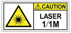
- Warning Invisible Laser Radiation. Do not expose users of telescopic optics. Class 1/1M Laser Products.
- Invisible laser radiation may be emitted from the end of the unterminated fiber cable or connector. Do not view directly with optical instruments. Viewing the laser output with certain optical instruments (for example, eye loupes, magnifiers, and microscopes) within a distance of 100 mm may pose an eye hazard.
| Fiber Type and Core Diameter (µm) | Wavelength (nm) | Max. Power (mW) | Beam divergence (rad) |
|---|---|---|---|
| SM 11 | 1200 – 1400 | 39 - 50 | 0.1 - 0.11 |
| MM 62.5 | 1200 – 14 | 150 | 0.18 NA |
| MM 50 | 1200 – 1400 | 135 | 0.17 NA |
| SM 11 | 1400 – 1600 | 112 - 145 | 0.11 - 0.13 |
21 CFR 1040

Pluggable optical modules comply with IEC 60825-1 Ed. 3 and 21 CFR 1040.10 and 1040.11 with or without exception for conformance with IEC 60825-1 Ed. 3 as described in Laser Notice No.56, dated May 8, 2019.
Conforme à la norme 21 CFR 1040.10 et 1040.11, sauf conformité avec la norme IEC 60825-1 Ed. 3., comme décrit dans l’avis relatif au laser no. 56, daté du 8 mai 2019.
Warranty Void if Opened

No serviceable parts inside. To avoid risk of electric shock, do not open.
FCC Compliance

Modifying the equipment without Cisco's authorization may result in the equipment no longer complying with FCC requirements for Class A digital devices. In that event, your right to use the equipment may be limited by FCC regulations, and you may be required to correct any interference to radio or television communications at your own expense. This equipment has been tested and found to comply with the limits for a Class A digital device, pursuant to Part 15 of the FCC Rules. These limits are designed to provide reasonable protection against harmful interference when the equipment is operated in a commercial environment. This equipment generates, uses, and can radiate radio frequency energ and, if not installed and used in accordance with the instruction manual, may cause harmful interference to radio communications. Operation of this equipment in a residential area is likely to cause harmful interference in which case users will be required to correct the interference at their own expense.
WEEE

 Feedback