Configuring Infra General Settings

Infra Configuration Dashboard

The Infra Configuration page displays an overview of all sites and inter-site connectivity in your Nexus Dashboard Orchestrator deployment and contains the following information:
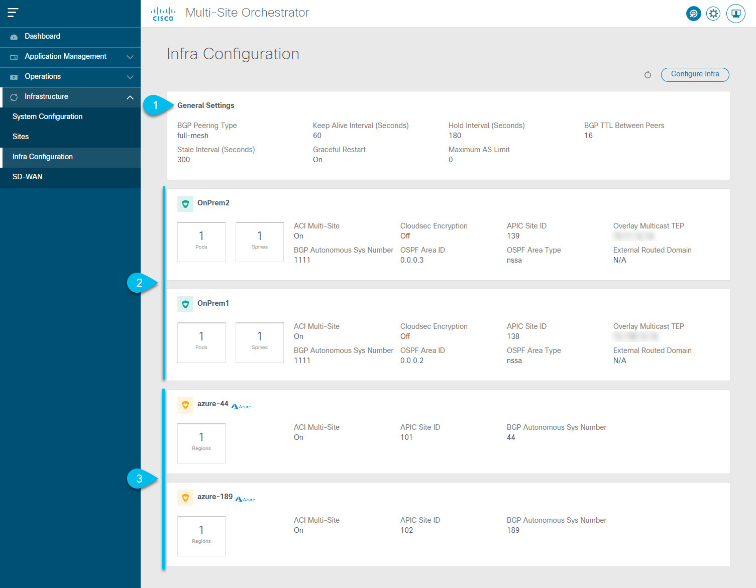
Figure 1. Infra Configuration Overview
  1. The General Settings tile displays information about BGP peering type and its configuration.

    This is described in detail in the next section.

  2. The On-Premises tiles display information about every on-premises site that is part of your Multi-Site domain along with their number of Pods and spine switches, OSPF settings, and overlay IPs.

    You can click on the Pods tile that displays the number of Pods in the site to show information about the Overlay Unicast TEP addresses of each Pod.

    This is described in detail in Configuring Infra for Cisco APIC Sites.

  3. The Cloud tiles display information about every cloud site that is part of your Multi-Site domain along with their number of regions and basic site information.

    This is described in detail in Configuring Infra for Cisco Cloud APIC Sites.

The following sections describe the steps necessary to configure the general fabric Infra settings. Fabric-specific requirements and procedures are described in the following chapters based on the specific type of fabric you are managing.

Before you proceed with Infra configuration, you must have configured and added the sites as described in previous sections.

In addition, any infrastructure changes such as adding and removing spine switches or spine node ID changes require a Nexus Dashboard Orchestrator fabric connectivity information refresh described in the Refreshing Site Connectivity Information as part of the general Infra configuration procedures.

Configuring Infra: General Settings

This section describes how to configure general Infra settings for all the sites.


Note


Some of the following settings apply to all sites, while others are required for specific type of sites (for example, Cloud APIC sites). Ensure that you complete all the required configurations in infra general settings before proceeding to the site-local settings specific to each site.


Procedure


Step 1

Log in to the Cisco Nexus Dashboard Orchestrator GUI.

Step 2

In the left navigation menu, select Infrastructure > Infra Configuration.

Step 3

In the main pane, click Configure Infra.

Step 4

In the left sidebar, select General Settings.

Step 5

Provide Control Plane Configuration.

  1. Select the Control Plane Configuration tab.

  2. Choose BGP Peering Type.

    • full-mesh—All border gateway switches in each site will establish peer connectivity with remote sites' border gateway switches.

      In full-mesh configuration, Nexus Dashboard Orchestrator uses the spine switches for ACI managed fabrics and border gateways for DCNM managed fabrics.

    • route-reflector—The route-reflector option allows you to specify one or more control-plane nodes to which each site establishes MP-BGP EVPN sessions. The use of route-reflector nodes avoids creating MP-BGP EVPN full mesh adjacencies between all the sites managed by NDO.

      For ACI fabrics, the route-reflector option is effective only for fabrics that are part of the same BGP ASN.

  3. In the Keepalive Interval (Seconds) field, enter the keep alive interval seconds.

    We recommend keeping the default value.

  4. In the Hold Interval (Seconds) field, enter the hold interval seconds.

    We recommend keeping the default value.

  5. In the Stale Interval (Seconds) field, enter stale interval seconds.

    We recommend keeping the default value.

  6. Choose whether you want to turn on the Graceful Helper option.

  7. Provide the Maximum AS Limit.

    We recommend keeping the default value.

  8. Provide the BGP TTL Between Peers.

    We recommend keeping the default value.

  9. Provide the OSPF Area ID.

    If you do not have any Cloud APIC sites, this field will not be present in the UI.

    This is OSPF area ID used by cloud sites for on-premises IPN peering, which you previously configured in the Cloud APIC for inter-site connectivity in earlier Nexus Dashboard Orchestrator releases.

Step 6

Provide the IPN Devices information.

If you do not plan to configure inter-site connectivity between on-premises and cloud sites, you can skip this step.

When you configure inter-site underlay connectivity between on-premises and cloud sites as described in later sections, you will need to select an on-premises IPN device which will establish connectivity to the cloud CSRs. These IPN devices must first be defined here before they are available in the on-premises site configuration screen, which is described in more detail in Configuring Infra: On-Premises Site Settings.

  1. Select the IPN Devices tab.

  2. Click Add IPN Device.

  3. Provide the Name and the IP Address of the IPN device.

    The IP address you provide will be used as the tunnel peer address from the Cloud APIC's CSRs, not the IPN device's management IP address.

  4. Click the check mark icon to save the device information.

  5. Repeat this step for any additional IPN devices you want to add.

Step 7

Provide the External Devices information.

If you do not have any Cloud APIC sites, this tab will not be present in the UI.

If you do not have any Cloud APIC sites in your Multi-Site domain or you do not plan to configure connectivity between cloud sites and branch routers or other external devices, you can skip this step.

The following steps describe how to provide information about any branch routers or external devices to which you want to configure connectivity from your cloud sites.

  1. Select the External Devices tab.

    This tab will only be available if you have at least one cloud site in your Multi-Site domain.

  2. Click Add External Device.

    The Add External Device dialogue will open.

  3. Provide the Name, IP Address, and BGP Autonomous System Number for the device.

    The IP address you provide will be used as the tunnel peer address from the Cloud APIC's CSRs, not the device's management IP address. The connectivity will be established over public Internet using IPSec.

  4. Click the check mark icon to save the device information.

  5. Repeat this step for any additional IPN devices you want to add.

After you have added all the external devices, ensure to complete the next step to provide the IPSec tunnel subnet pools from with the internal IP addresses will be allocated for these tunnels.

Step 8

Provide the IPSec Tunnel Subnet Pools information.

If you do not have any Cloud APIC sites, this tab will not be present in the UI.

There are two types of subnet pools that you can provide here:

  • External Subnet Pool—used for connectivity between cloud site CSRs and other sites (cloud or on-premises).

    These are large global subnet pools that are managed by Nexus Dashboard Orchestrator. The Orchestrator, creates smaller subnets from these pools and allocates them to sites to be used for inter-site IPsec tunnels and external connectivity IPsec tunnels.

    You must provide at least one external subnet pool if you want to enable external connectivity from one or more of your cloud sites.

  • Site-Specific Subnet Pool—used for connectivity between cloud site CSRs and external devices.

    These subnets can be defined when the external connectivity IPsec tunnels must be in a specific range. For example, where a specific subnet is already being used to allocate IP addresses to the external router and you want to continue using those subnets for IPsec tunnels for NDO and cloud sites. These subnets are not managed by the Orchestrator and each subnet is assigned to a site in its entirety to be used locally for external connectivity IPsec tunnels.

    If you do not provide any named subnet pools but still configure connectivity between cloud site's CSRs and external devices, the external subnet pool will be used for IP allocation. .

Note


The minimum mask length for both subnet pools is /24.

To add one or more External Subnet Pools:

  1. Select the IPSec Tunnel Subnet Pools tab.

  2. In the External Subnet Pool area, click +Add IP Address to add one or more external subnet pools.

    This subnet will be used to address the IPsec tunnel interfaces and loopbacks of the Cloud Routers used for on-premises connectivity, which you previously configured in the Cloud APIC for inter-site connectivity in earlier Nexus Dashboard Orchestrator releases.

    The subnets must not overlap with other on-premises TEP pools, should not begin with 0.x.x.x or 0.0.x.x, and should have a network mask between /16 and /24, for example 30.29.0.0/16.

  3. Click the check mark icon to save the subnet information.

  4. Repeat these substeps for any additional subnet pools you want to add.

To add one or more Named Subnet Pools:

  1. Select the IPSec Tunnel Subnet Pools tab.

  2. In the Named Subnet Pool area, click +Add IP Address to add one or more external subnet pools.

    The Add Named Subnet Pool dialogue will open.

  3. Provide the subnet Name.

    You will be able to use the subnet pool's name to choose the pool from which to allocate the IP addresses later on.

  4. Click +Add IP Address to add one or more subnet pools.

    The subnets must have a network mask between /16 and /24and not begin with 0.x.x.x or 0.0.x.x, for example 30.29.0.0/16.

  5. Click the check mark icon to save the subnet information.

    Repeat the steps if you want to add multiple subnets to the same named subnet pool.

  6. Click Save to save the named subnet pool.

  7. Repeat these substeps for any additional named subnet pools you want to add.


What to do next

After you have configured general infra settings, you must still provide additional information for site-specific configurations based on the type of sites (on-premises ACI, cloud ACI, or on-premises fabric managed by DCNM) you are managing. Follow the instructions described in the following sections to provide site-specific infra configurations.