Supported Topologies

Connection Options

You can use these connection options for the Cisco Hybrid Cloud Networking Solution:

  • With IPsec: If the connectivity from the on-premises data center to the cloud is over the public Internet, then an IPsec tunnel is required for establishing a secure channel. In this situation, the border gateway (BGW) will be connected to an on-premises IPsec-capable device, such as an ASR 1000 or a Cisco Catalyst 8000V. This device establishes IPsec tunnels with the Catalyst 8000Vs in the cloud. The on-premises BGWs can then leverage this "IPsec secured underlay" to build VXLAN tunnels with the Catalyst 8000Vs in the cloud.

  • Without IPsec: If the BGWs are connected to the public cloud using Direct Connect (AWS) or ExpressRoute (Azure), then enabling IPsec is optional. In this case, a VXLAN connection is employed between the on-premises VXLAN EVPN data centers and the Cisco Catalyst 8000Vs on top of those dedicated circuits.

The following sections provide more detailed information on the supported topologies available using either of these connection options:

Supported Topologies with IPsec (Single-Cloud)

The following table shows how BGP EVPN control plane adjacencies can be established between on-premises sites and on-premises to a cloud site, and how IPsec is leveraged to establish underlay connectivity between on-premises sites and a single cloud site.


Note

Each of the following figures show a simple example. In a real life scenario, there might be redundant devices deployed for each role.


BGP EVPN Between On-Premises Sites

BGP EVPN and IPsec to the Cloud Site

Full-Mesh

Through Hub Site Only

  • BGP EVPN to the Cloud Site: Full-Mesh

  • IPsec to the Cloud Site: Through Shared IPsec Router Only

Full-Mesh

Option 1

Option 3

Option 5

With Route Server

Option 2

Option 4

N/A

Option 1

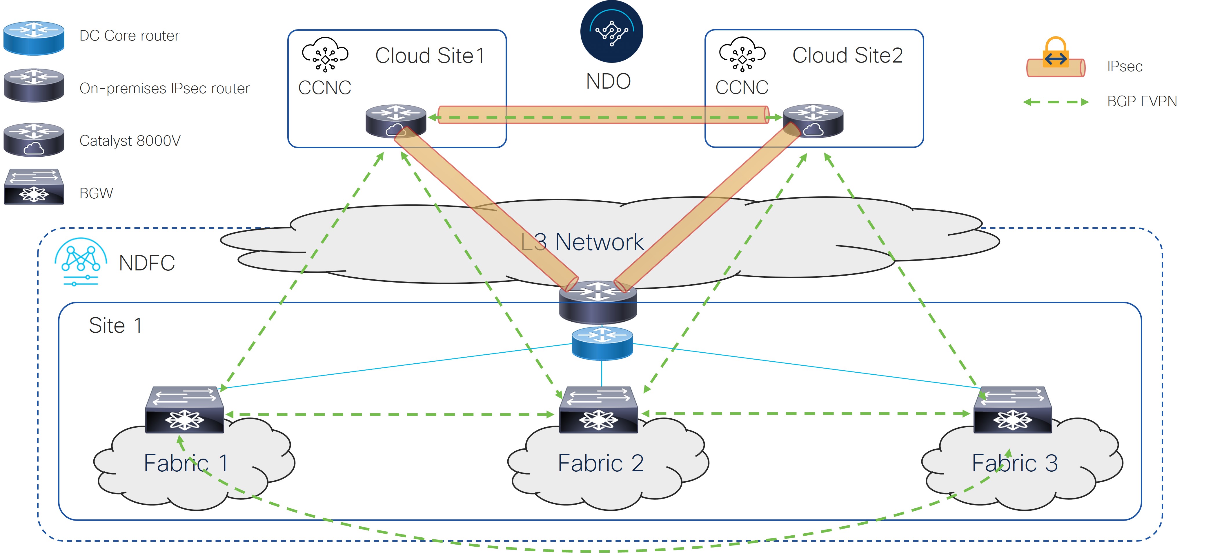
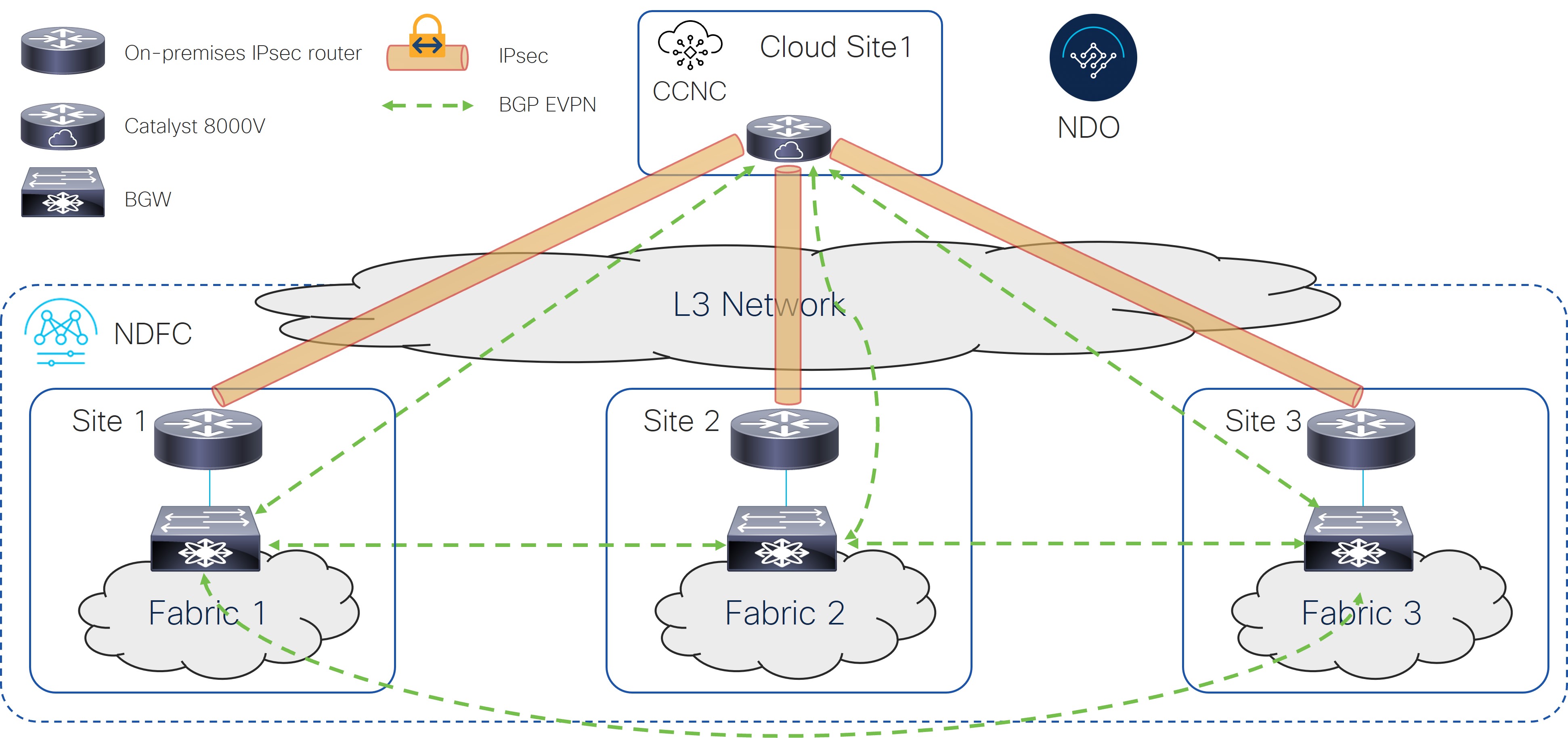
The following figure shows an example of a single-cloud connection using IPsec, where:

  • The BGW nodes on all the on-premises sites establish full-mesh BGP EVPN adjacencies between them.

  • The Cisco Catalyst 8000V in the cloud site establishes IPsec tunnels with core routers deployed in each on-premises site and full-mesh BGP EVPN adjacencies with all the BGW devices on the on-premises sites.

Figure 1.

Option 2

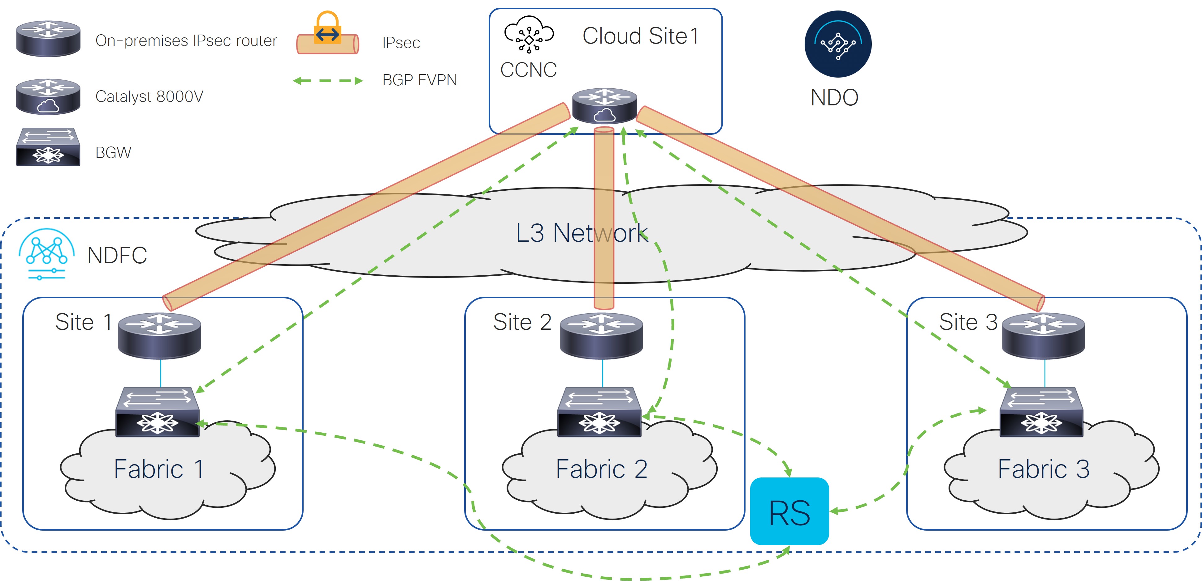
The following figure shows an example of a single-cloud connection using IPsec, where:

  • The BGW nodes on all the on-premises sites establish BGP EVPN adjacencies with a Route Server (RS) control plane node.

  • The Cisco Catalyst 8000V in the cloud site establishes full-mesh IPsec tunnels with core routers deployed in each on-premises site and BGP EVPN adjacencies with all the BGW devices on the on-premises sites.


Note

It is currently not supported to peer the Cisco Catalyst 8000Vs with the Route Server control node.


Figure 2.

Option 3

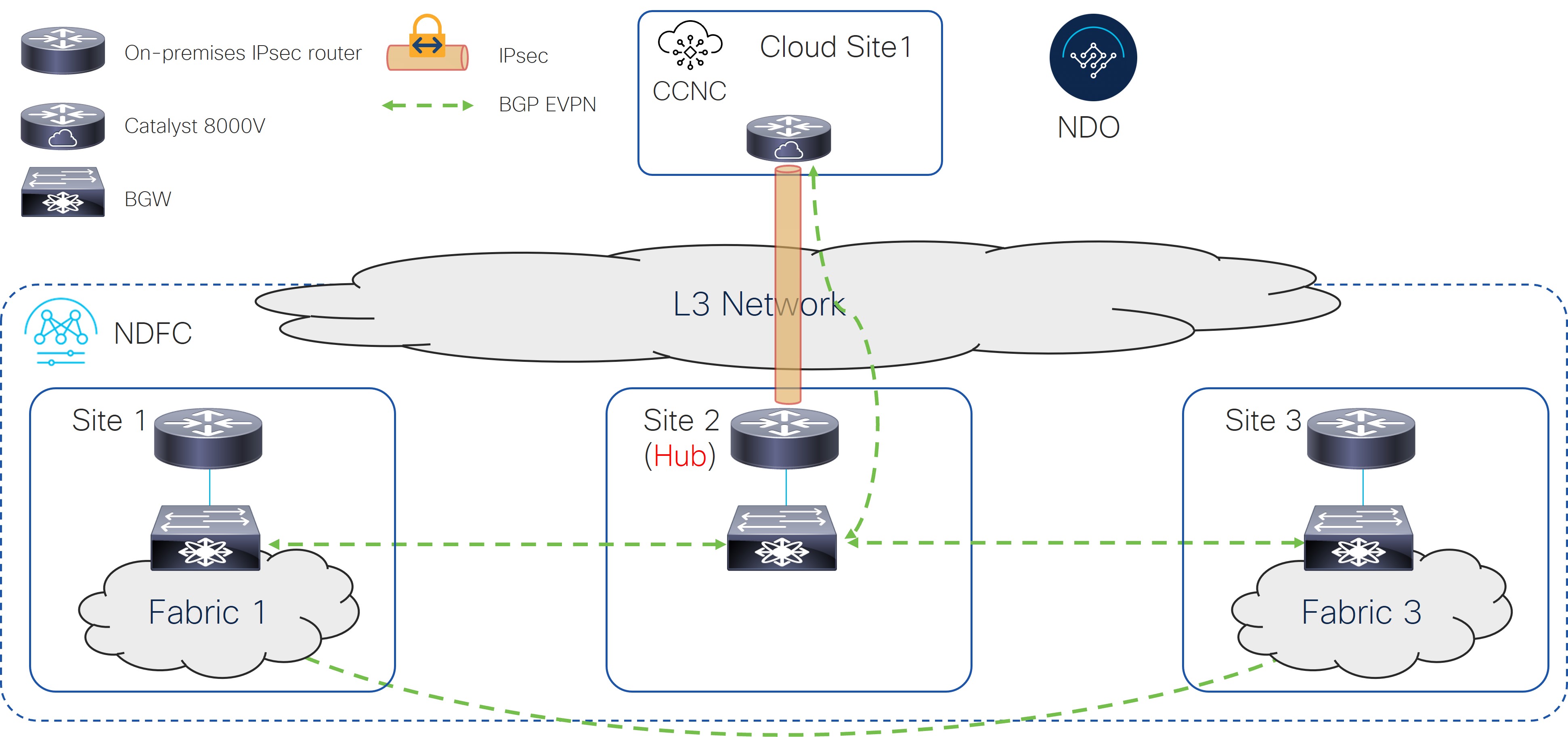
The following figure shows an example of a single-cloud connection using IPsec, where:

  • The BGW nodes on all the on-premises sites establish full-mesh BGP EVPN adjacencies between them.

  • The Cisco Catalyst 8000V in the cloud site establishes an IPsec tunnel only with the core router deployed in a specific on-premises Hub Site and BGP EVPN adjacency only with the BGW device on the Hub Site.

  • The BGW deployed in Site 2 (to which the Cisco Catalyst 8000V peers EVPN) cannot have a fabric behind it. It is only used to exchange prefixes between the on-premises and the cloud site.

Figure 3.

Option 4

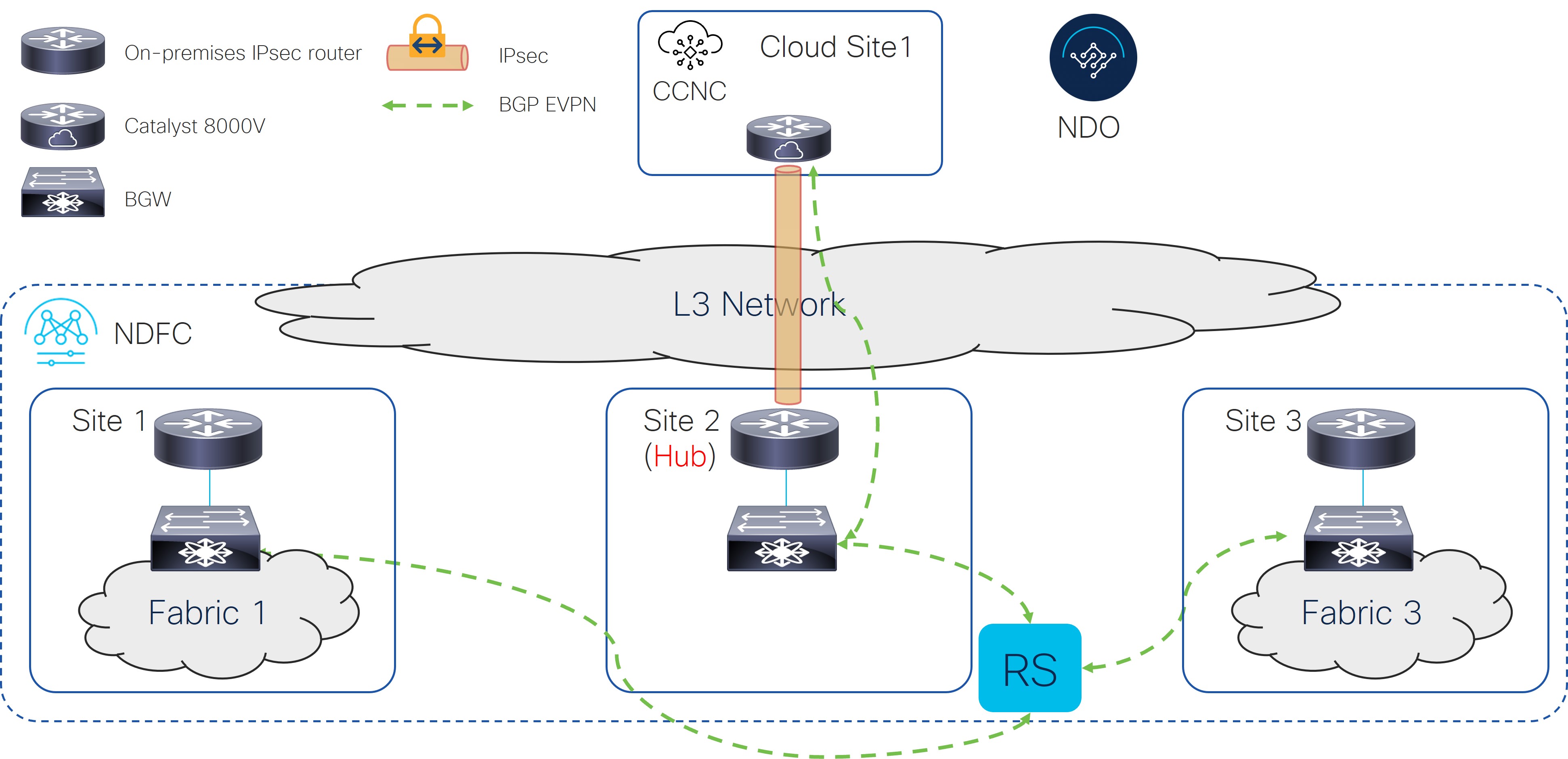
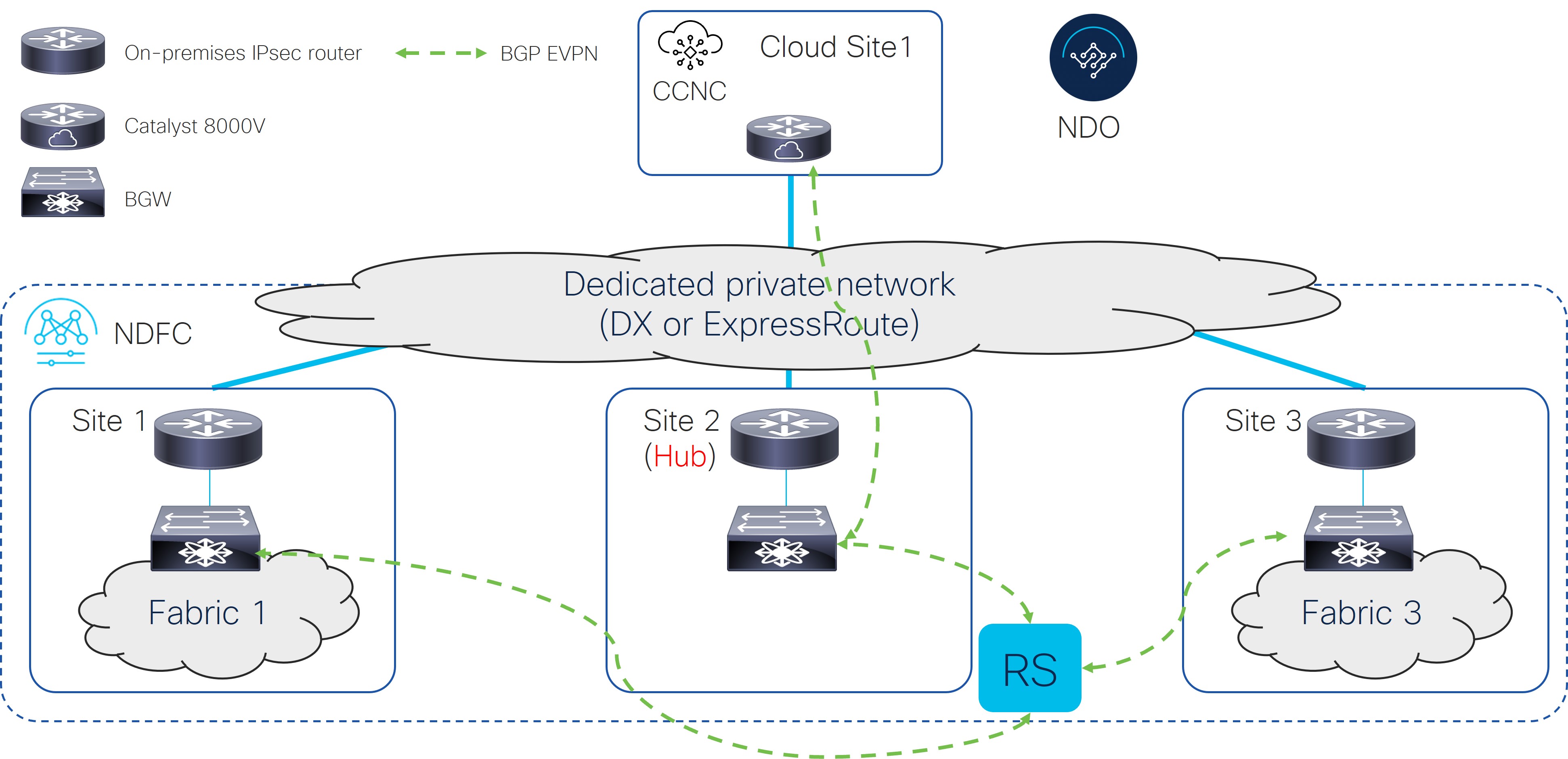
The following figure shows an example of a single-cloud connection using IPsec, where:

  • The BGW nodes on all the on-premises sites establish BGP EVPN adjacencies with a Route Server control plane node.

  • The Cisco Catalyst 8000V in the cloud site establishes an IPsec tunnel only with the core router deployed in a specific on-premises Hub Site and EVPN adjacency only with the BGW device on the Hub Site.

  • The BGW deployed in Site 2 (to which the Cisco Catalyst 8000V peers EVPN) cannot have a fabric behind it. It is only used to exchange prefixes between the on-premises and the cloud site.

Figure 4.

Option 5

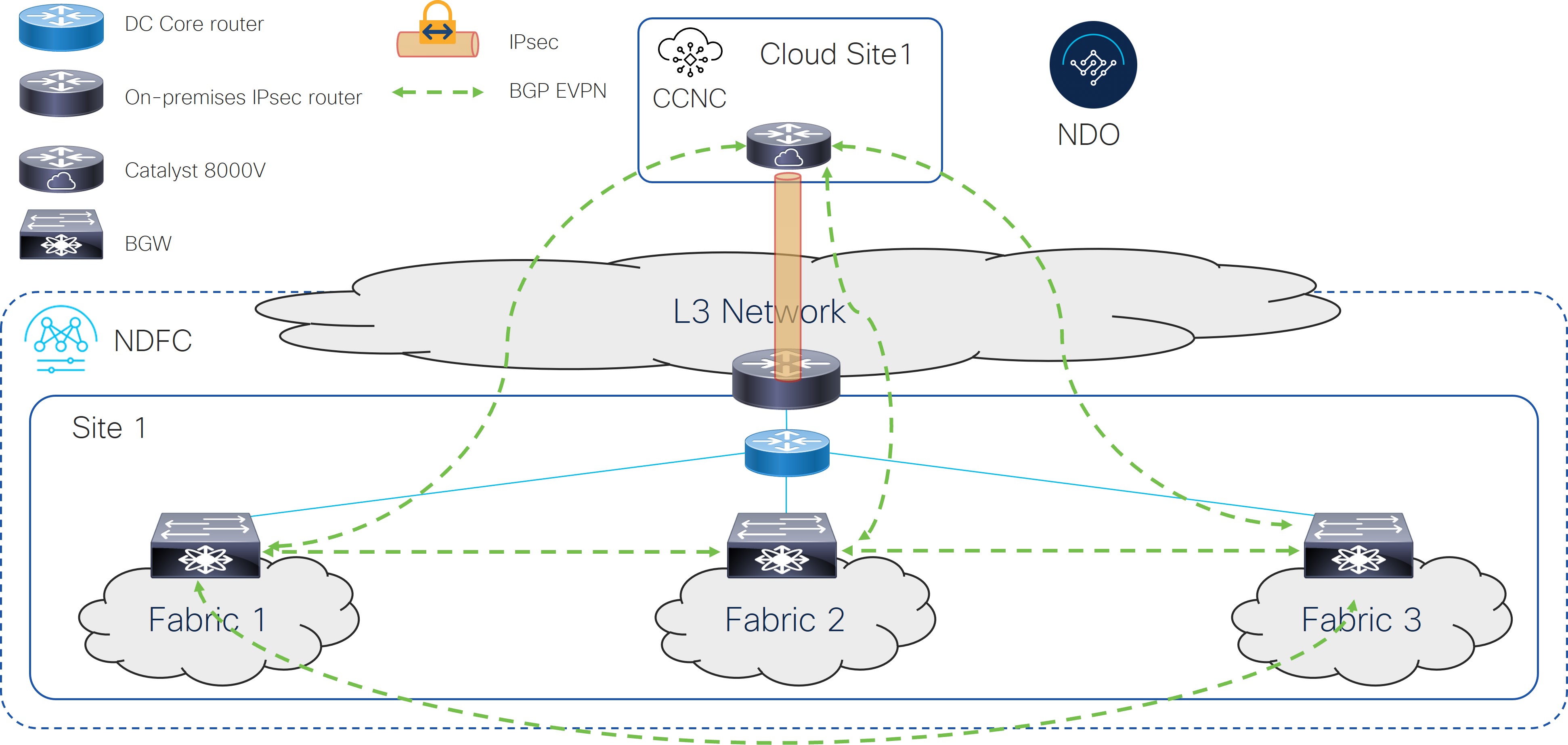
The following figure shows an example of a single-cloud connection using IPsec, where:

  • The BGW nodes on all the on-premises sites establish full-mesh EVPN adjacencies between them.

  • The Cisco Catalyst 8000V in the cloud site establishes full-mesh BGP EVPN adjacencies with all the BGW devices on the on-premises sites.

  • The IPsec connection to the cloud site is through a shared IPsec router only.

Figure 5.

Supported Topologies with IPsec (Multi-Cloud)

The following table shows how BGP EVPN control plane adjacencies can be established between on-premises sites and on-premises to cloud sites, and how IPsec is leveraged to establish underlay connectivity between on-premises sites and multiple cloud sites.


Note

Each of the following figures show a simple example. In a real life scenario, there might be redundant devices deployed for each role.


BGP EVPN Between On-Premises Sites

BGP EVPN and IPsec to the Cloud Sites

BGP EVPN and IPsec between Cloud Sites

Full-Mesh

Through Hub Site Only

  • BGP EVPN to the Cloud Site: Full-Mesh

  • IPsec to the Cloud Site: Through Hub Site Only

Full-Mesh

Option 1

Option 3

Option 5

Full-Mesh

With Route Server

Option 2

Option 4

N/A

Option 1

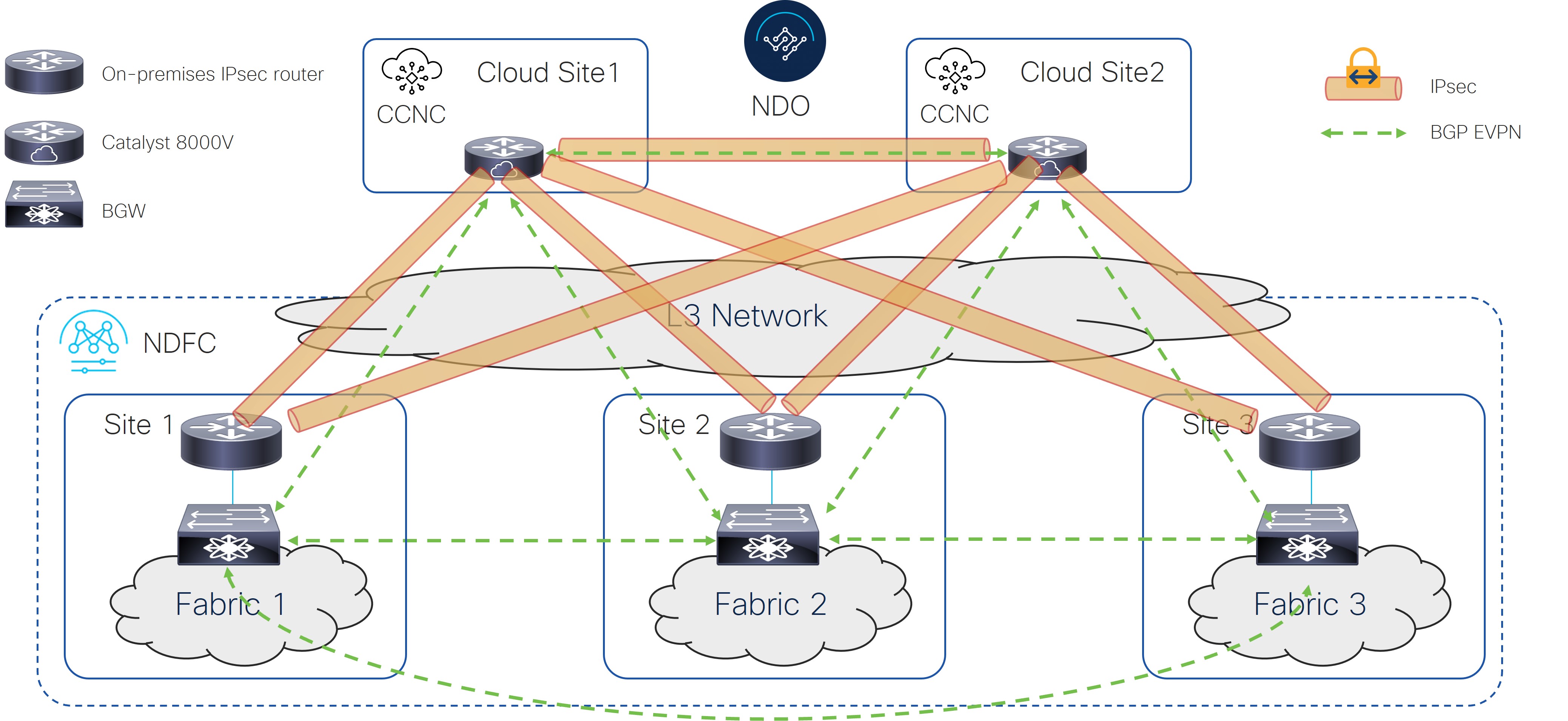
The following figure shows an example of a multi-cloud connection using IPsec, where:

  • The BGW nodes on all the on-premises sites establish full-mesh BGP EVPN adjacencies between them.

  • The Cisco Catalyst 8000Vs in the cloud sites establish IPsec tunnels with core routers deployed in each on-premises site and full-mesh EVPN adjacencies with all the BGW devices on the on-premises sites.

  • The Cisco Catalyst 8000Vs in different cloud sites establish full-mesh IPsec tunnels and EVPN adjacencies between them.

Figure 6.

Option 2

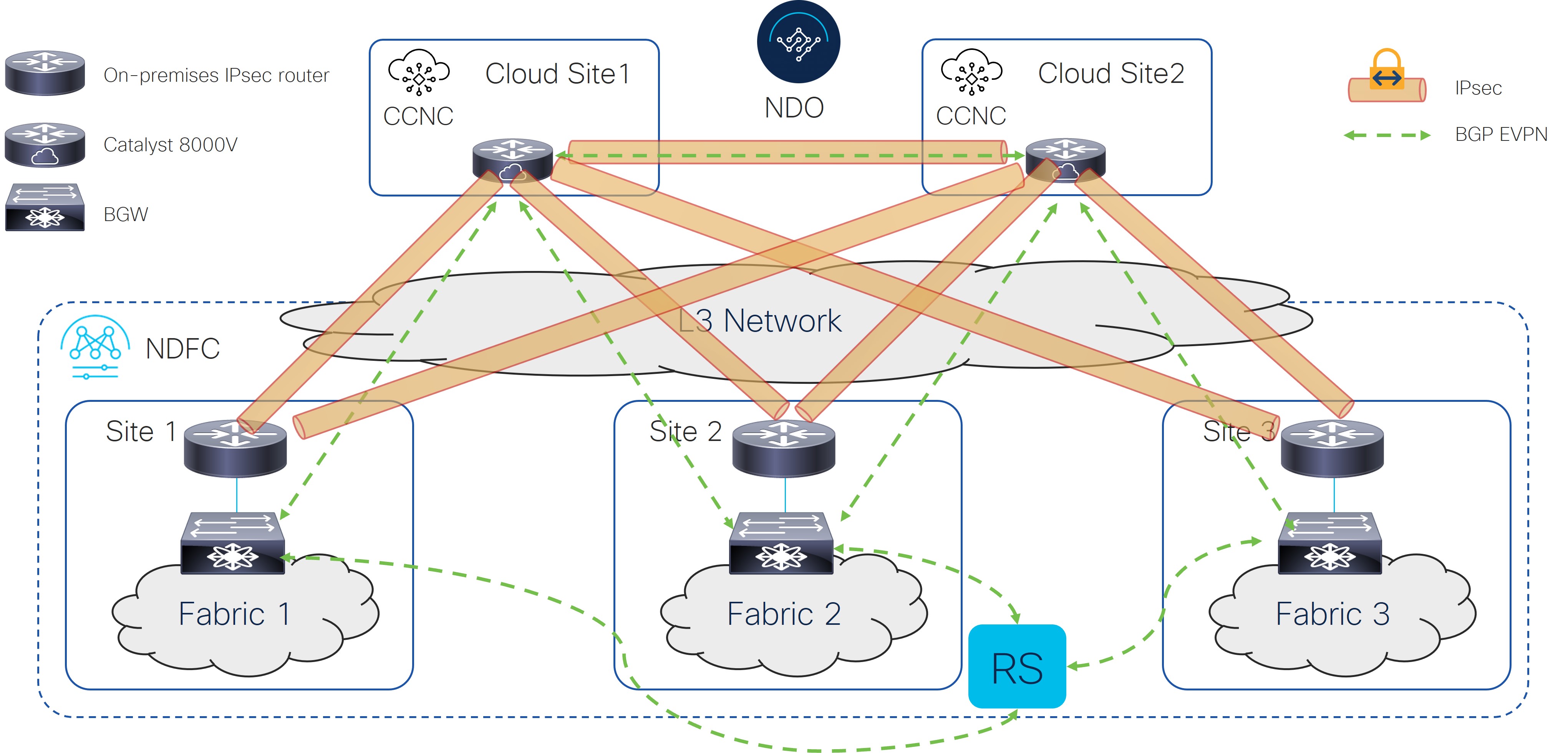
The following figure shows an example of a multi-cloud connection using IPsec, where:

  • The BGW nodes on all the on-premises sites establish BGP EVPN adjacencies with a Route Server control plane node.

  • The Cisco Catalyst 8000Vs in the cloud sites establish IPsec tunnels with core routers deployed in each on-premises site and full-mesh BGP EVPN adjacencies with all the BGW devices on the on-premises sites.

  • The cloud routers peer BGP EVPN with the BGW on the Hub Site.

Figure 7.

Option 3

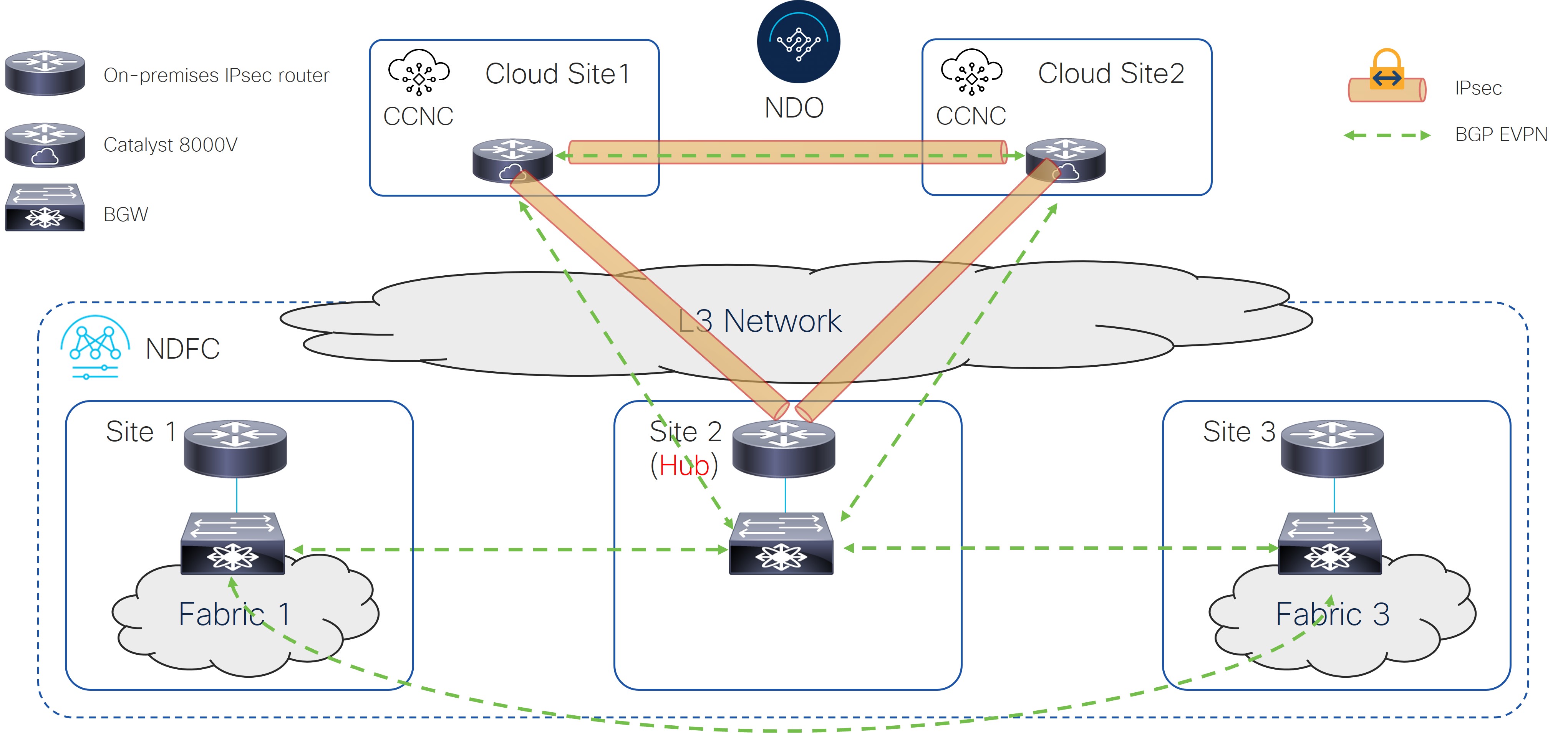
The following figure shows an example of a multi-cloud connection using IPsec, where:

  • The BGW nodes on all the on-premises sites establish full-mesh EVPN adjacencies between them.

  • The Cisco Catalyst 8000Vs in the cloud sites establish IPsec tunnels only with the core router deployed in a specific on-premises Hub Site and EVPN adjacency only with the BGW device on the Hub Site.

  • The Cisco Catalyst 8000Vs in different cloud sites establish full-mesh IPsec tunnels and EVPN adjacencies between them.

  • The BGW deployed in Site 2 (to which the Cisco Catalyst 8000V peers EVPN) cannot have a fabric behind it. It is only used to exchange prefixes between the on-premises and cloud sites.

Figure 8.

Option 4

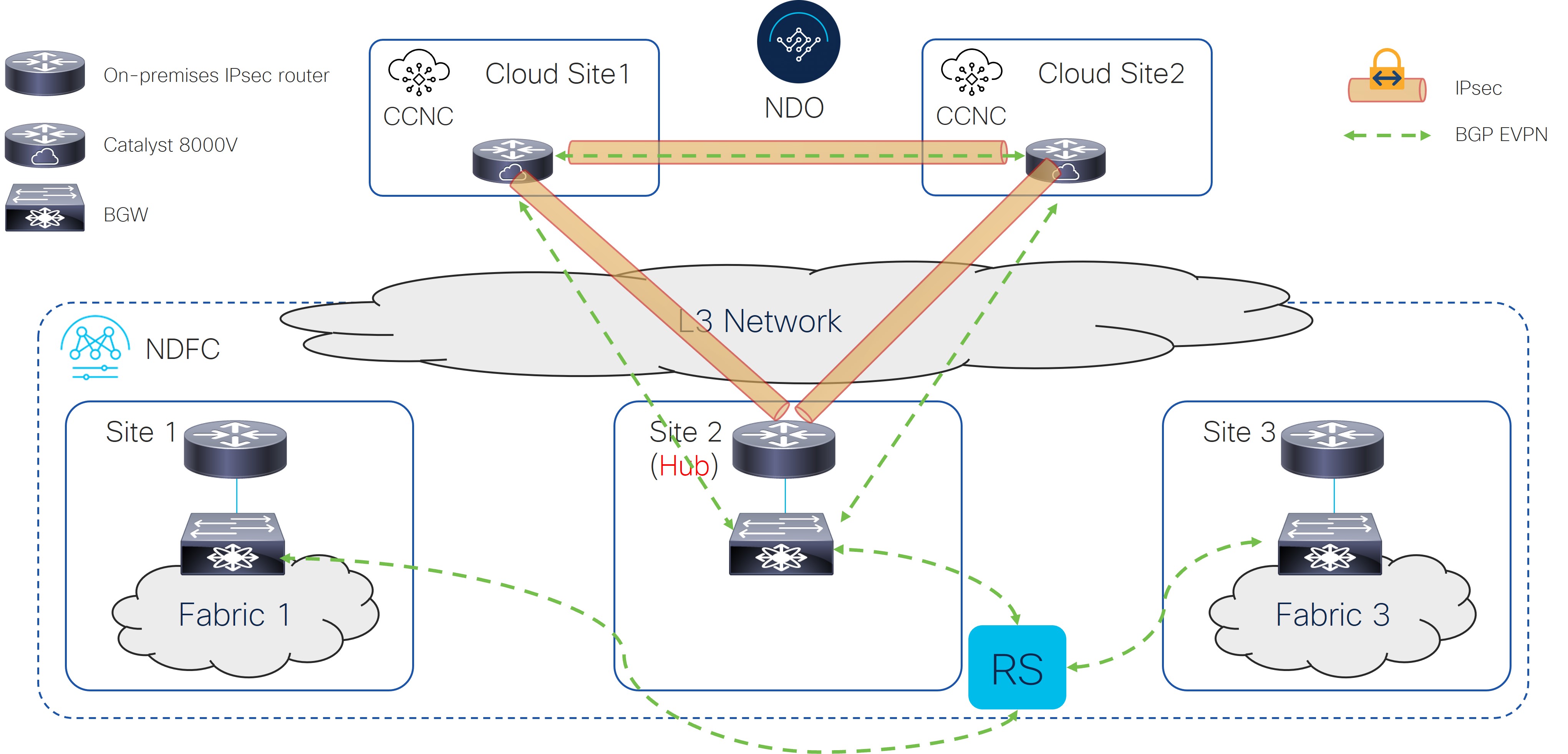
The following figure shows an example of a multi-cloud connection using IPsec, where:

  • The BGW nodes on all the on-premises sites establish BGP EVPN adjacencies with a Route Server control plane node.

  • The Cisco Catalyst 8000Vs in the cloud sites establish IPsec tunnels only with the core router deployed in a specific on-premises Hub Site and BGP EVPN adjacency only with the BGW device on the Hub Site.

  • The cloud routers peer BGP EVPN with the BGW on the Hub Site.

  • The BGW deployed in Site 2 (to which the Cisco Catalyst 8000V peers EVPN) cannot have a fabric behind it. It is only used to exchange prefixes between the on-premises and cloud sites.

Figure 9.

Option 5

The following figure shows an example of a multi-cloud connection using IPsec, where:

  • The BGW nodes on all the on-premises sites establish full-mesh EVPN adjacencies between them.

  • The Cisco Catalyst 8000V in the cloud sites establishes full-mesh BGP EVPN adjacencies with all the BGW devices on the on-premises sites.

  • The Cisco Catalyst 8000Vs in the cloud sites establish IPsec tunnels only with the core router deployed in a specific on-premises Hub Site.

  • The Cisco Catalyst 8000Vs in different cloud sites establish full-mesh IPsec tunnels and EVPN adjacencies between them.

Figure 10.

Supported Topologies without IPsec (Single Cloud)

The following table shows how BGP EVPN control plane adjacencies can be established between on-premises sites or on-premises to a cloud site.

BGP EVPN Between On-Premises Sites

BGP EVPN to the Cloud Site

Full-Mesh

Through Hub Site

Full-Mesh

Option 1

Option 3

With Route Server

Option 2

Option 4


Note

Each of the following figures show a simple example. In a real life scenario, there might be redundant devices deployed for each role.


Option 1

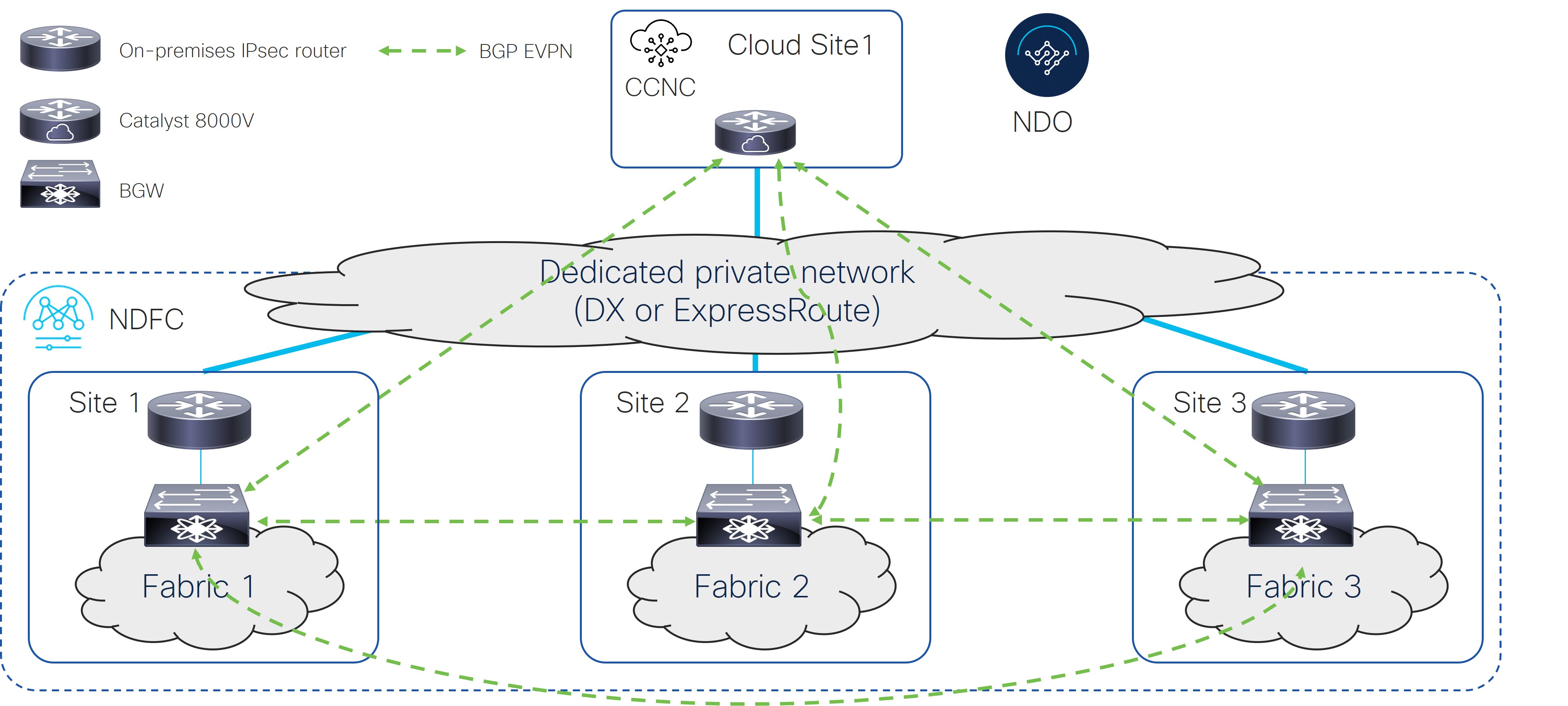
The following figure shows an example of a single-cloud connection without IPsec, where:

  • The BGW nodes on all the on-premises sites establish full-mesh BGP EVPN adjacencies between them.

  • The Cisco Catalyst 8000V in the cloud site establishes full-mesh BGP EVPN adjacencies with all the BGW devices on the on-premises sites.

Figure 11.

Option 2

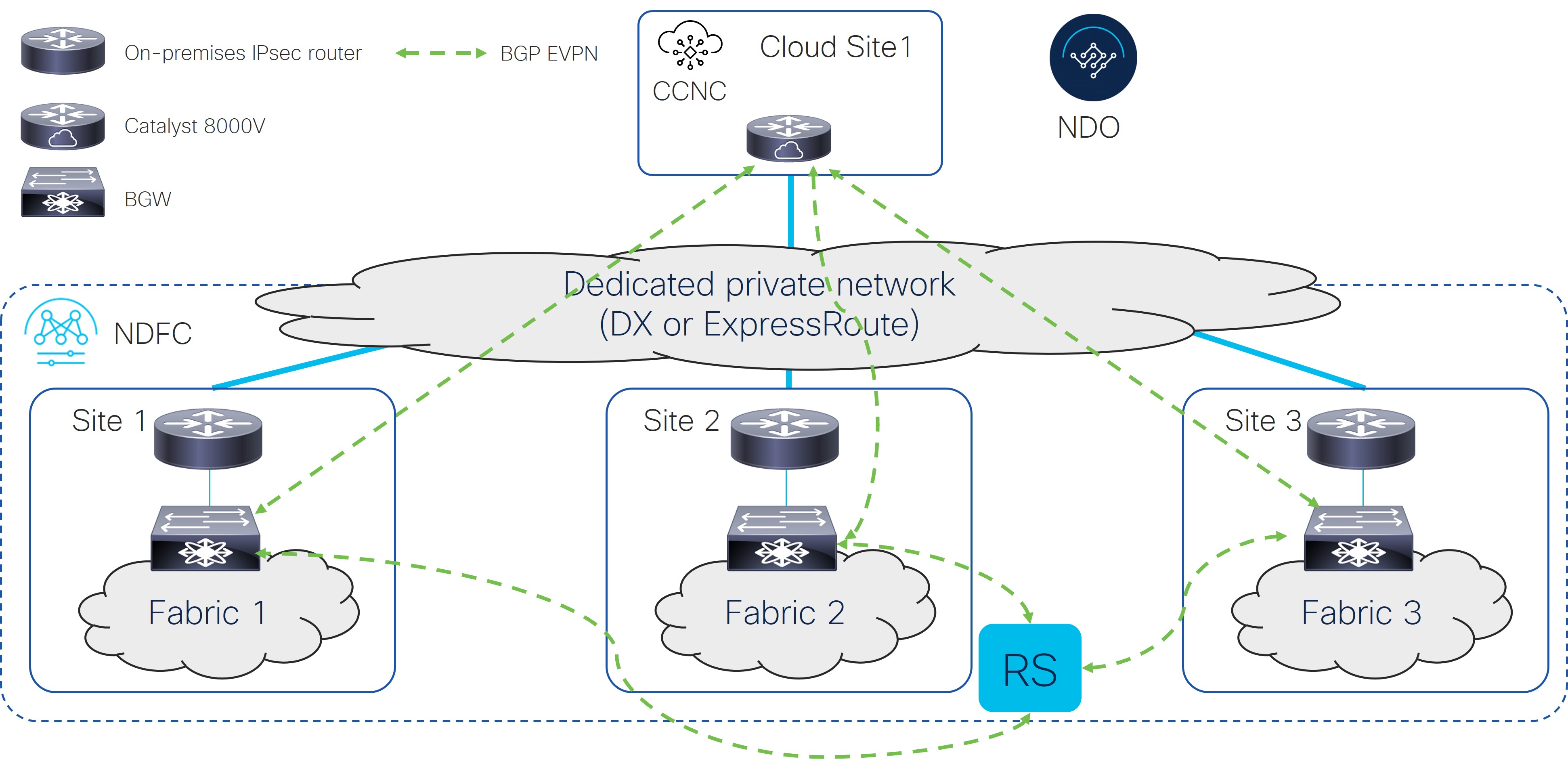
The following figure shows an example of a single-cloud connection without IPsec, where:

  • The BGW nodes on all the on-premises sites establish BGP EVPN adjacencies with a Route Server (RS) control plane node.

  • The Cisco Catalyst 8000V in the cloud site establishes full-mesh BGP EVPN adjacencies with all the BGW devices on the on-premises sites.

Figure 12.

Option 3

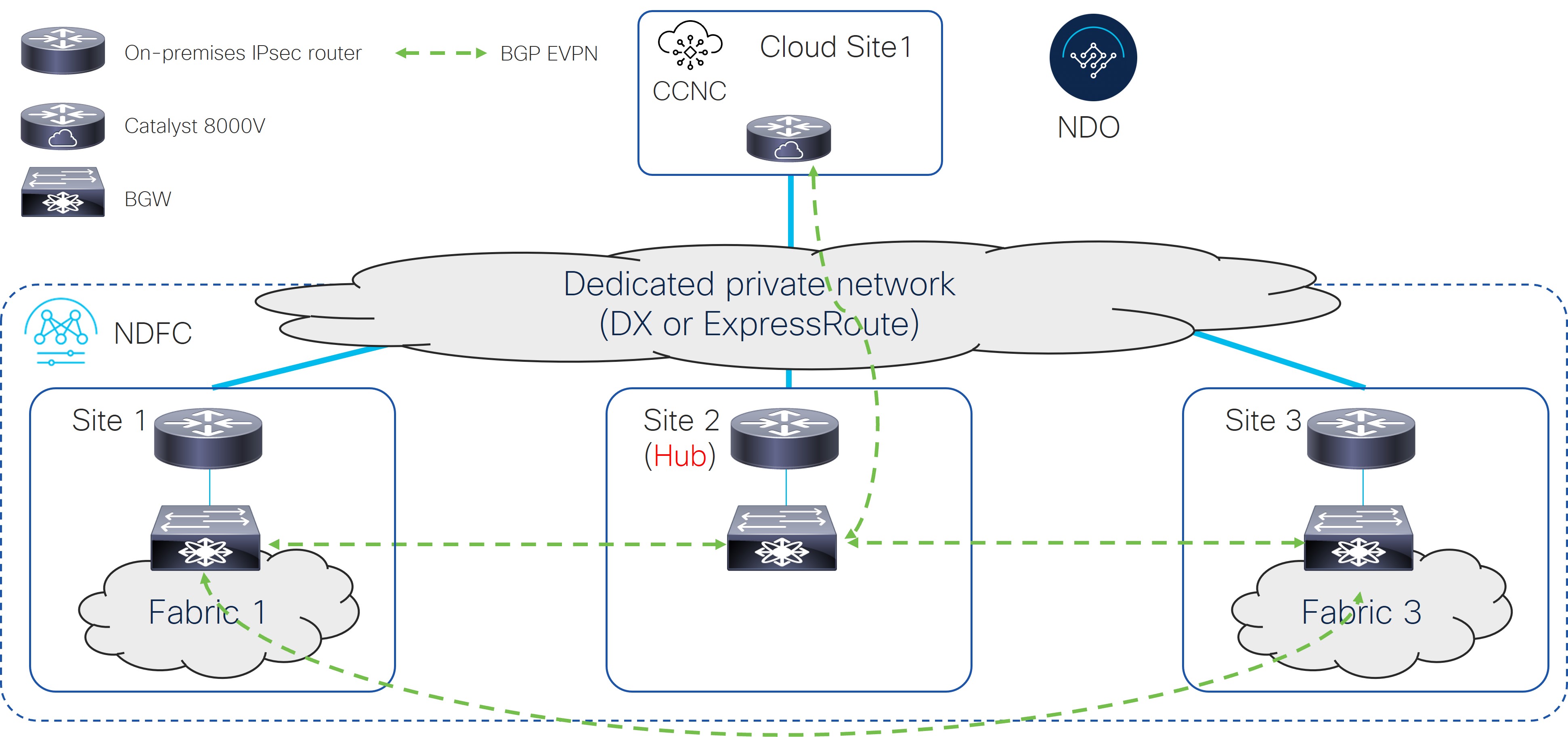
The following figure shows an example of a single-cloud connection without IPsec, where:

  • The BGW nodes on all the on-premises sites establish full-mesh BGP EVPN adjacencies between them.

  • The Cisco Catalyst 8000V in the cloud site establishes a BGP EVPN adjacency only with the BGW device on the Hub Site.

  • The BGW deployed in Site 2 (to which the Cisco Catalyst 8000V peers EVPN) cannot have a fabric behind it. It is only used to exchange prefixes between the on-premises and the cloud site.

Figure 13.

Option 4

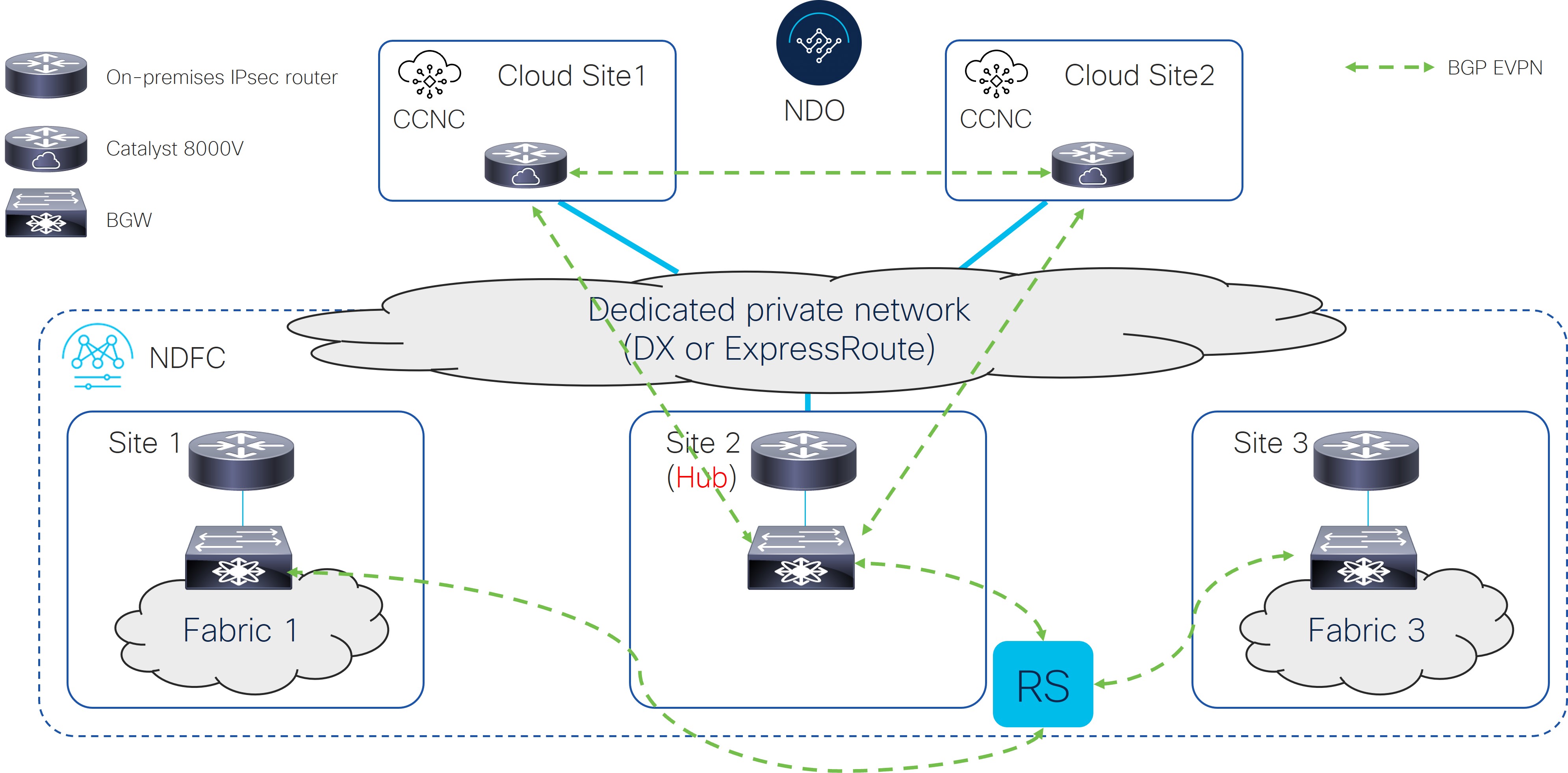
The following figure shows an example of a single-cloud connection without IPsec, where:

  • The BGW nodes on all the on-premises sites establish BGP EVPN adjacencies with a Route Server control plane node.

  • The Cisco Catalyst 8000V in the cloud site establishes a BGP EVPN adjacency only with the BGW device on the Hub Site.

  • The BGW deployed in Site 2 (to which the Cisco Catalyst 8000V peers EVPN) cannot have a fabric behind it. It is only used to exchange prefixes between the on-premises and the cloud site.

Figure 14.

Supported Topologies without IPsec (Multi-Cloud)

The following table shows how BGP EVPN control plane adjacencies can be established between on-premises sites or on-premises to cloud sites.

BGP EVPN Between On-Premises Sites

BGP EVPN to the Cloud Sites

BGP EVPN between Cloud Sites

Full-Mesh

Through Hub Site

Full-Mesh

Option 1

Option 3

Full-Mesh

Route Server

Option 2

Option 4


Note

Each of the following figures show a simple example. In a real life scenario, there might be redundant devices deployed for each role.


Option 1

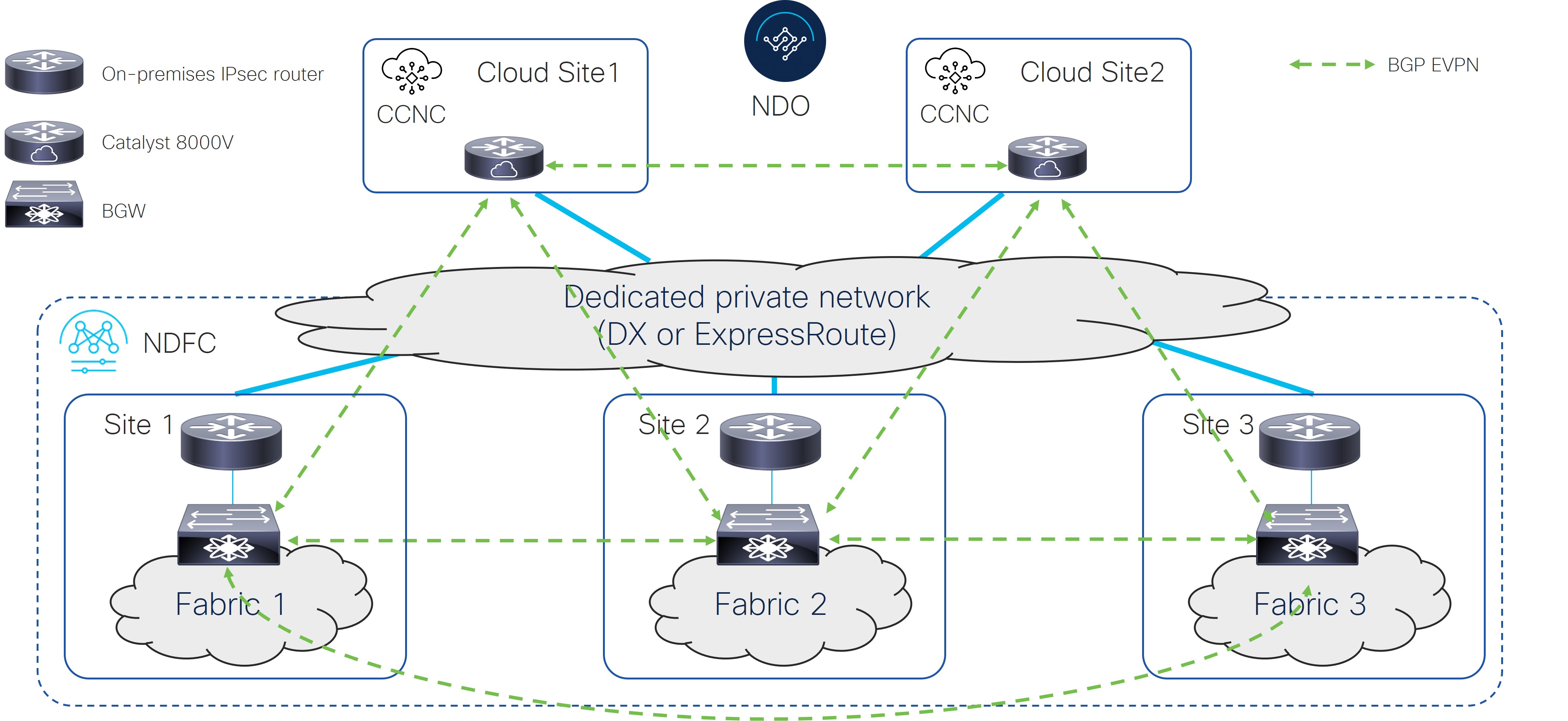
The following figure shows an example of a multi-cloud connection without IPsec, where:

  • The BGW nodes on all the on-premises sites establish full-mesh BGP EVPN adjacencies between them.

  • The Cisco Catalyst 8000Vs in the cloud sites establish full-mesh BGP EVPN adjacencies with all the BGW devices on the on-premises sites.

  • The Cisco Catalyst 8000Vs in different cloud sites establish full-mesh BGP EVPN adjacencies between them.

Figure 15.

Option 2

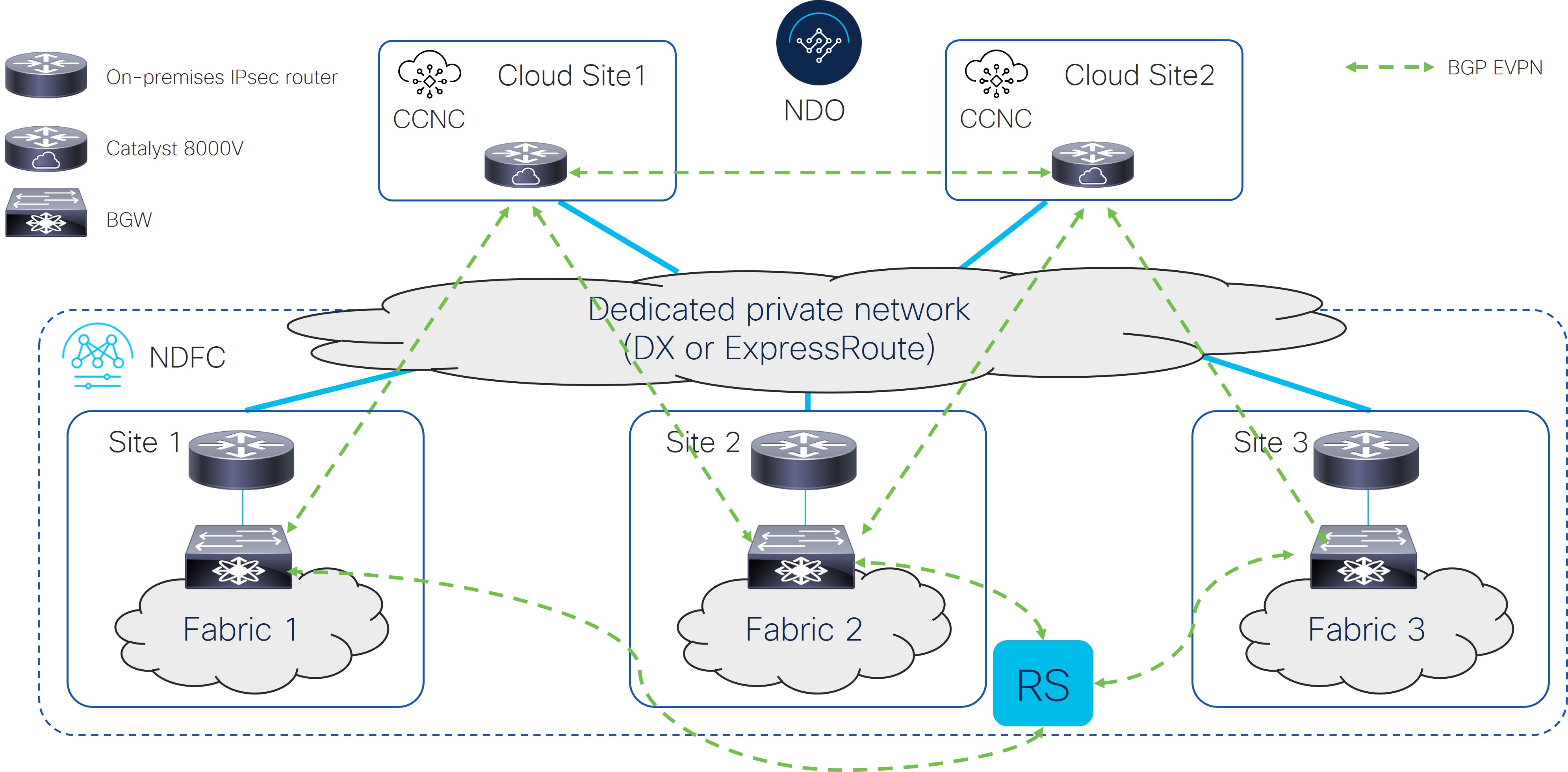
The following figure shows an example of a multi-cloud connection without IPsec, where:

  • The BGW nodes on all the on-premises sites establish BGP EVPN adjacencies with a Route Server control plane node.

  • The Cisco Catalyst 8000Vs in the cloud sites establish full-mesh BGP EVPN adjacencies with all the BGW devices on the on-premises sites.

  • The Cisco Catalyst 8000Vs in different cloud sites establish full-mesh BGP EVPN adjacencies between them.

Figure 16.

Option 3

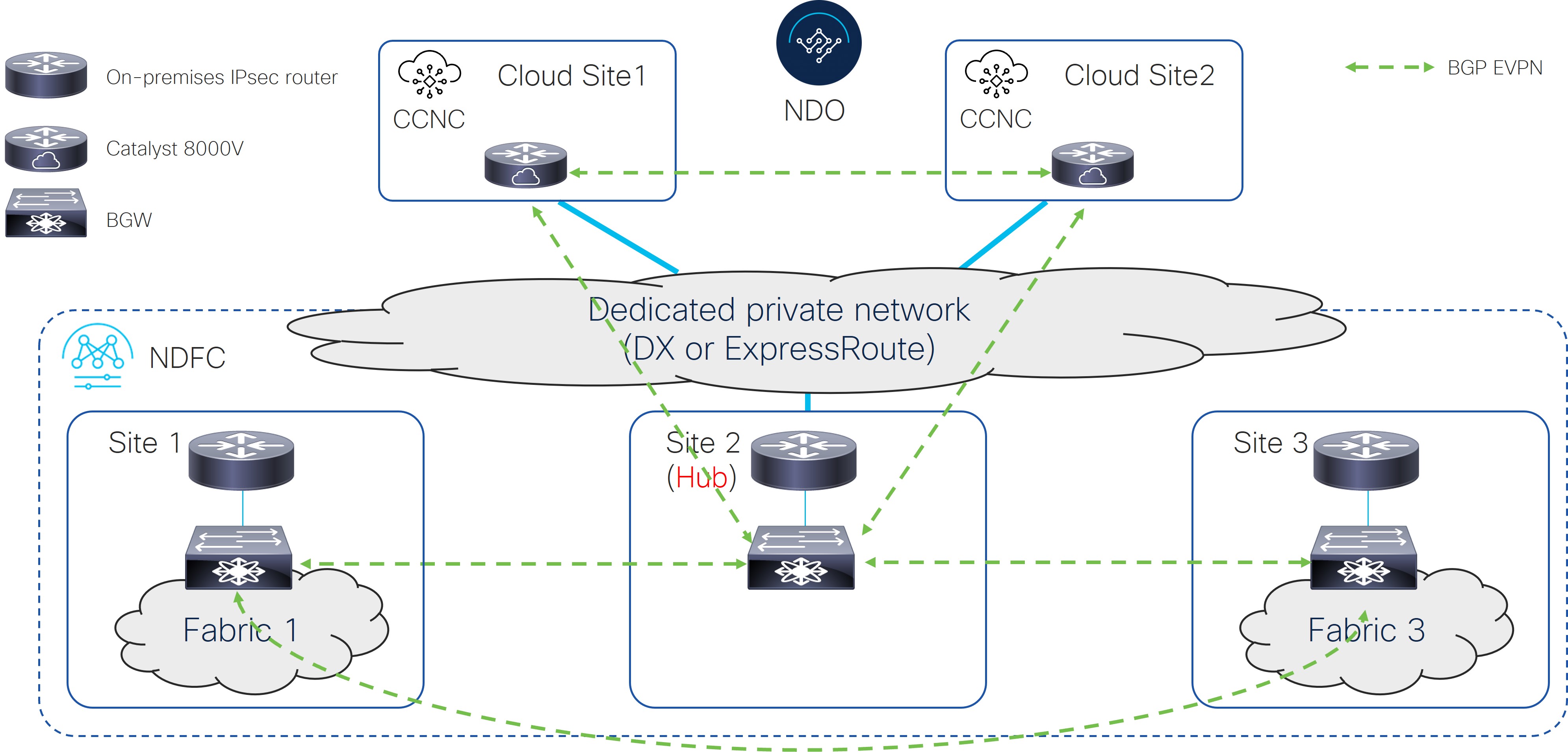
The following figure shows an example of a multi-cloud connection without IPsec, where:

  • The BGW nodes on all the on-premises sites establish full-mesh BGP EVPN adjacencies between them.

  • The Cisco Catalyst 8000Vs in the cloud sites establish BGP EVPN adjacencies only with the BGW device on the Hub Site.

  • The Cisco Catalyst 8000Vs in different cloud sites establish full-mesh BGP EVPN adjacencies between them.

  • The BGW deployed in Site 2 (to which the Cisco Catalyst 8000V peers EVPN) cannot have a fabric behind it. It is only used to exchange prefixes between the on-premises and cloud sites.

Figure 17.

Option 4

The following figure shows an example of a multi-cloud connection without IPsec, where:

  • The BGW nodes on all the on-premises sites establish BGP EVPN adjacencies with a Route Server control plane node.

  • The Cisco Catalyst 8000Vs in the cloud sites establish BGP EVPN adjacencies only with the BGW device on the Hub Site.

  • The Cisco Catalyst 8000Vs in different cloud sites establish full-mesh BGP EVPN adjacencies between them.

  • The BGW deployed in Site 2 (to which the Cisco Catalyst 8000V peers EVPN) cannot have a fabric behind it. It is only used to exchange prefixes between the on-premises and cloud sites.

Figure 18.