Network Services
Cisco cnBR empowers you to create a number of easily composable, scalable, and resilient network services.
DHCP Relay Service
Cisco cnBR acts as a Dynamic Host Configuration Protocol (DHCP) relay agent to implement features such as DHCP relay, Lease Query (LQ), IPv6 Prefix Delegation (PD), and to provision static IP addresses for subscribers by using source address verification (SAV).
DHCP Relay
When the Cisco cnBR acts as a relay agent, it forwards requests and replies between clients and servers when they are not on the same physical subnet. Relay agent forwarding is different from normal IP router forwarding. In normal IP router forwarding, IP datagrams are forwarded between networks transparently. However, in relay agent forwarding, relay agent receives a DHCP message and then generates a new DHCP message to send through another interface.
When a DHCP client requests an IP address from a DHCP server, for instance DHCPv4, the client sends a DHCPDISCOVER broadcast message to locate the DHCP server. Relay agent forwards the packets between the DHCP client and the DHCP server. The DHCP server provides configuration parameters, such as IP address, MAC address, domain name, and a lease for the IP address, to the client in a DHCPOFFER unicast message.
User Guidelines:
-
By default, DHCP relay is enabled on Cisco cnBR. DHCP relay depends on two Cisco cnBR services in the multiple instances environment - BGP agent and Relay proxy.
-
DHCP relay agent configuration is based on service group.
-
DHCP server receives DHCP request. If multiple DHCP servers are configured, all these servers receive relay packets.
-
The v4Net/v6Net defines all the IP scopes for the subscriber's DHCP destination IP address. This configuration must be consistent with the configuration of the DHCP server. If multiple subscriber nets are configured, use the first scope as the default scope.
-
Cisco cnBR can also assign a specific server or IP scope for a subscriber. For more information, see Policy Based Relay.
-
By default, the DHCPv6 Client Link-Layer Address option (RFC 6939) is enabled. You cannot disable this option.
DHCPv6 Client Link-Layer Address Option (RFC 6939)
The following table provides description of the various features and their release information
|
Feature Name |
Release Information |
Feature Description |
|---|---|---|
|
Support for DHCPv6 client link-layer address (RFC 6939) |
Cisco cnBR 21.2 |
This support provides the client's link-layer address in the DHCPv6 messages which are sent towards the server. |
Cisco cnBR supports DHCPv6 client link-layer address option (RFC 6939). It defines an optional mechanism and the related DHCPv6 option to allow first-hop DHCPv6 relay agents (relay agents that are connected to the same link as the client) to provide the client's link-layer address in the DHCPv6 messages which are sent towards the server.
      0                   1                   2                   3
      0 1 2 3 4 5 6 7 8 9 0 1 2 3 4 5 6 7 8 9 0 1 2 3 4 5 6 7 8 9 0 1
     +-+-+-+-+-+-+-+-+-+-+-+-+-+-+-+-+-+-+-+-+-+-+-+-+-+-+-+-+-+-+-+-+
     | OPTION_CLIENT_LINKLAYER_ADDR  |           option-length       |
     +-+-+-+-+-+-+-+-+-+-+-+-+-+-+-+-+-+-+-+-+-+-+-+-+-+-+-+-+-+-+-+-+
     |   link-layer type (16 bits)   |                               |
     +-+-+-+-+-+-+-+-+-+-+-+-+-+-+-+-+                               |
     |               link-layer address (variable length)            |
     |                                                               |
     |                                                               |
     +-+-+-+-+-+-+-+-+-+-+-+-+-+-+-+-+-+-+-+-+-+-+-+-+-+-+-+-+-+-+-+-+
The following table provides information on the DHCPv6 client link-layer address (RFC 6939) parameters and their description
|
Name |
Description |
|---|---|
|
option-code |
OPTION_CLIENT_LINKLAYER_ADDR (79). |
|
option-length |
2 + length of MAC address. |
|
link-layer type |
CPE or CM MAC address type. The link-layer type must be a valid hardware type assigned by the IANA, as described in the RFC0826. |
|
link-layer address |
MAC address of the CPE or CM. |
 Note |
By default, the DHCPv6 Client Link-Layer Address option (RFC 6939) is enabled. You cannot disable this option. |
Policy Based Relay
Policy Based Relay allows subscribers with different device classes to be classified into different IP ranges.
When the relay agent handles subscriber DHCP packets, Cisco cnBR can identify its device class based on the TLV (Tag, Length, Value) in the DHCP packets. Then the Cisco cnBR uses a predefined relay policy to assign a specific server to get DHCP address, or notify the server to assign its DHCP address in a specific IP range.
User Guidelines:
-
Define the v4serverip/v6serverip in the dhcpServers.
-
Define the giaddr/linkaddr with associated v4Nets and/or v6Nets. The address is the prefix of the v4Nets/v6Nets.
-
If there is no specific v4serverip/v6serverip for the device class, the subscriber requests are forwarded to all the servers defined.
-
If there is no specific giaddr/linkaddr for the device class, the subscribers get the IP from the first default range.
DHCPv6 Prefix Delegation
In the IPv6 networking, you can use the DHCPv6 prefix delegation (PD) to assign network address prefix, automate configuration, and provision the public routable addresses for the network. For example, in home networks, home routers use the DHCPv6 protocol to request a network prefix from the ISP's DHCPv6 server. After you assign the network prefix, the ISP routes this network prefix to your home router. Then the home router starts displaying the new addresses to hosts on the network.
After the PD router comes online, it gets the assigned network prefix from the DHCP server.
ARP/NDP Glean and Lease Query
As a relay agent, Cisco cnBR stores all subscriber DHCP information after DHCP is completed. Based on this information, routing is established for subscribers. However, there are several cases when subscriber information is unavailable, such as a modem reset, resulting in routing being no longer available for subscribers. When these subscribers access the network, Cisco cnBR rebuilds the data path by using ARP/NDP glean or lease query.
When using ARP/NDP Glean, Cisco cnBR can trust the packets that come from the cable side network. After the ARP/NS is received and the source IP is updated in the configured IP ranges, Cisco cnBR rebuilds a data path for the source MAC. This method is open to MAC spoofing.
In contrast, when using Lease Query, Cisco cnBR doesn't trust the cable side network. When Cisco cnBR receives the upstream packet with no data path route, it sends a LEASEQUERY request to DHCP server. After DHCP server gets the request and confirms that the RESPONSE, the MAC and IP are released from DHCP server, Cisco cnBR rebuilds the data path. Otherwise, Cisco cnBR drops the packets.
User guidelines:
-
Enable or disable ARP/NDP Glean and Lease Query on demand.
-
Lease Query checks the source IP with the v4Nets/v6Nets configuration. If the source IP of the packets isn't in the range, then Lease Query discards the packet.
-
Use ARP/NDP Glean and Lease Query with Source Address Verification (SAV).
Source Address Verification (SAV)
In addition to DHCP leased IP address, Cisco cnBR allows static IP address by provisioning SAV group.
A SAV group is a group of IPv4 or IPv6 prefixes. Cisco cnBR uses these prefixes to authenticate a cable modem (CM). You can configure a CM with an IPv4 or IPv6 prefix that belongs to a particular SAV group. The time, length, and the value (TLV) 43.7.1 specify the group name to which a given CM belongs. If the source IP address of a packet from a CM belongs to the configured prefix in a SAV group, the Cisco CMTS considers it as an authorized packet.
You can configure a maximum of 255 SAV groups on a Cisco cnBR. Each SAV group contains up to four IPv4s, IPv6s, or a combination of both prefixes. The total number of the prefixes is not more than four.
During registration, CMs communicate their configured static prefixes to the CMTS using TLV 43.7.1 and TLV 43.7.2. The TLV 43.7.1 specifies the SAV prefix group name that the CM belongs to, and TLV 43.7.2 specifies the actual IPv4 or IPv6 prefix. Each CM can have a maximum of four prefixes configured. When the Cisco CMTS receives these TLVs, it identifies whether the specified SAV group and the prefixes are already configured on the Cisco CMTS. If these are configured, the Cisco CMTS associates them to the registering CM. However if these are not configured, the Cisco CMTS automatically creates the specified SAV group and prefixes before associating them to the registering CM.
The Cisco CMTS considers the SAV group name and the prefixes that are provided by these TLVs to be valid. The packets received from the CM, with the source IP address belonging to the prefix specified by the TLV, are authorized packets. For example, if a given CM has an SAV prefix of 10.10.10.0/24, and the source IP address of a packet received from this CM (or CPE behind the CM) is in the subnet 10.10.10.0/24, then it is an authorized packet.
User guidelines:
-
SAV configuration is global and not for each service group.
-
SAV doesn’t check the MAC/IP binding. You can assign the static IP to any MAC.
-
By default, SAV is disabled. You can enable it on demand.
ARP/NDP Proxy
All cable modems and subscribers are behind the HFC network. As a proxy, Cisco cnBR relays the ARP/NDP requests to the CM.
With ARP/NDP proxy enabled, Cisco cnBR can respond the ARP/NDP, and the DS lease query is not to be triggered.
Mobility Scopes
If the subscribers are allowed to roam between different IPv4 and IPv6 scopes, the mobility scopes contain all the IPv4 and IPv6 scopes granted to the subscribers. This configuration is optional.
Configure DHCP Relay Service
The DHCP relay service operates in a similar way as other Cisco CMTS products. You can configure it with Autodeployer Script, or by importing the whole Cisco cnBR configuration YAML file to the desired Cisco cnBR using Cisco Operations Hub. The imported configuration file overwrites the existing configuration and activates the new configuration.
Update the DHCP Relay configuration using Autodeployer reconfig (Preferred)
After configuring the DHCP Relay using the Autodeployer during deployment, you can modify the dhcp block in the L3 profile file and run the AutoDeployer configuration script again to update the configuration.
Note |
Rerunning AutoDeployer configuration script causes all the RPDs/SGs to be deleted and added. |
Update DHCP Relay Configuration Using cnBR Manager
After configuring the DHCP Relay using the Autodeployer during deployment, you can also update the configuration using the cnBR Manager UI.
Use the following steps to update the DHCP Relay configuration:
Procedure
| Step 1 |
On the Cisco Operations Hub, click the Cisco Operations Hub main menu button. |
| Step 2 |
Choose cnBR Manager > cnBRs to open the cnBR Clusters page. |
| Step 3 |
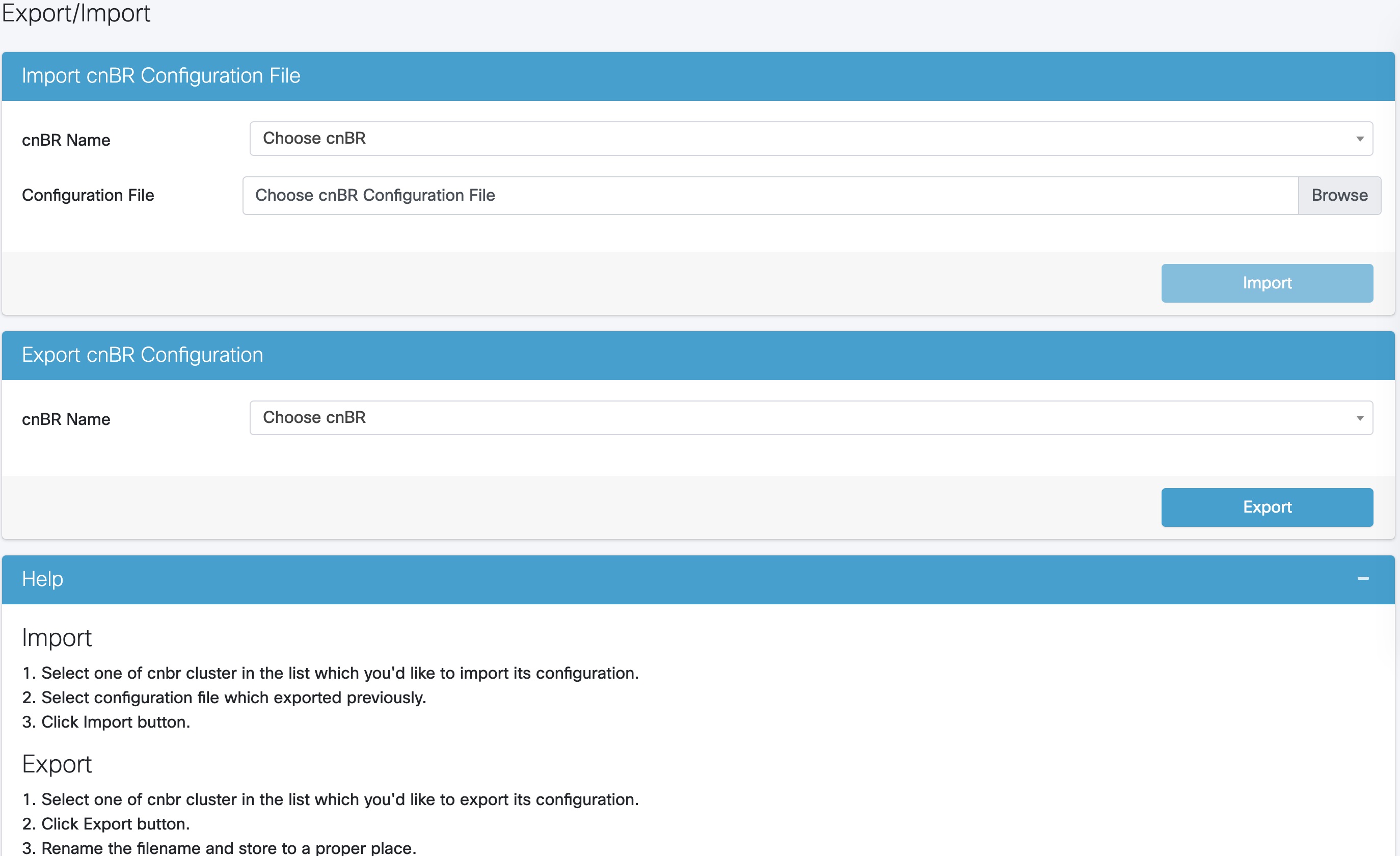
Click Import & Export cnBR to open the Export/Import page. |
| Step 4 |
In the Export cnBR Configuration pane, from the drop-down list, choose the required Cisco cnBR to update. |
| Step 5 |
Click Export to get the current SG configuration of the selected Cisco cnBR. |
| Step 6 |
In the |
| Step 7 |
Save the updated configuration file on the local disk. |
| Step 8 |
In the Import cnBR Configuration File pane, from the drop-down list, choose the Cisco cnBR to update. |
| Step 9 |
Click Browse to locate the file which you updated (saved at Step 5). |
| Step 10 |
Click Import to upload the updated SG configuration to the selected Cisco cnBR. |
Configure DHCP Relay using Autodeployer Script
In the AutoDeployer script L3 profile file, the DHCP Relay configuration is saved in the dhcp section. It is applied to all Service Groups on the Cisco cnBR. The following is an example configuration:
"Dhcp":
    {
        "ArpGlean":true,
        "ArpProxy":true,
        "ipv4Lq": false,
        "NdGlean":true,
        "NdProxy":true,
        "ipv6Lq":false,
        "dhcpServers":["80.80.80.3",
                      "81.81.81.3",
                      "2001:80:80:80::3",
                      "2001:81:81:81::3"
        ],
        "V4Nets":["90.90.90.1/24",
                  "91.91.91.1/24",
                  "92.92.92.1/24"
        ],
        "V6Nets":["2001:90:90:90::1/64",
                  "2001:91:91:91::1/64",
                  "2001:92:92:92::1/64"
        ],
        "RelayPolicies":[
          {"deviceClass": "HOST",
          "v4serverip": "80.80.80.3",
          "v6serverip": "2001:80:80:80::3",
          "giaddr": "90.90.90.1",
          "linkaddr": "2001:90:90:90::1"
          },
          {"deviceClass": "STB",
          "v4serverip": "81.81.81.3",
          "v6serverip": "2001:81:81:81::3",
          "giaddr": "91.91.91.1",
          "linkaddr": "2001:91:91:91::1"
          },
          {"deviceClass": "PS",
          "giaddr": "92.92.92.1",
          "linkaddr": "2001:92:92:92::1"
          },
          {"deviceClass": "EROUTER",
          "v4serverip": "80.80.80.3",
          "v6serverip": "2001:80:80:80::3",
          },
          {"deviceClass": "DVA",
          "giaddr": "90.90.90.1",
          "linkaddr": "2001:90:90:90::1"
          },
          {"deviceClass": "MTA",
          "giaddr": "91.91.91.1",
          "linkaddr": "2001:91:91:91::1"
          }
        ],
        "mobilityScopes":["90.90.90.1/24",
                          "91.91.91.1/24",
                          "92.92.92.1/24",
                          "2001:90:90:90::1/64",
                          "2001:91:91:91::1/64",
                          "2001:92:92:92::1/64"
        ]
    }
See Configure Cisco cnBR Using Autodeployer for additional information.
Configure DHCP Relay
The following table provides information on the DHCP relay field names, their descriptions, type and enforcement
| Field Name | Description | Type | Enforcement |
|---|---|---|---|
| dhcpServers | DHCP server IPv4 and IPv6 addresses | IPv4 or IPv6 | Required |
| v4Nets | IPv4 range to which the subscriber's DHCP address belongs | CIDR (Classless Inter-Domain Routing) | Required |
| v6Nets | IPv6 range to which the subscriber's DHCP address belongs | CIDR (Classless Inter-Domain Routing) | Required |
    "Dhcp":
    {
        // all the DHCP servers IP, V4 and V6
        "dhcpServers":[
                        "81.81.81.3",
                        "24.24.24.3",
                        "2001:81:81:81::3",
                        "2001:24:24:24::3"
                      ],
        // all the V4 subnets for the subscribers in this SG
        "v4Nets":[
                    "90.90.90.1/24",
                    "91.91.91.1/24",
                    "92.92.92.1/24",
                    "93.93.93.1/24",
                    "94.94.94.1/24",
                    "95.95.95.1/24"
                    "96.96.96.1/24",
                    "97.97.97.1/24",
                ],
        // all the V6 subnets for the subscribers in this SG
        "v6Nets":[
                    "2001:90:90:90::1/64",
                    "2001:91:91:91::1/64",
                    "2001:92:92:92::1/64",
                    "2001:93:93:93::1/64",
                    "2001:94:94:94::1/64",
                    "2001:95:95:95::1/64",
                    "2001:96:96:96::1/64",
                    "2001:97:97:97::1/64"
                ],
    }
Configure DHCP Relay Policy
| Field Name | Description | Type | Enforcement |
|---|---|---|---|
| deviceClass | The device class for each subscriber | String | Required |
| v4serverip | The server to which the DHCP request is forwarded | IPv4 | Optional |
| v6serverip | The server to which the DHCPv6 request is forwarded | IPv6 | Optional |
| giaddr | The IP range to which the DHCPv4 address belongs; the giaddr is the IP address in the v4Nets | IPv4 | Optional |
| linkaddr | The IP range to which the DHCPv6 address belongs; the linkaddr is the IP address in the v6Nets | IPv6 | Optional |
    "Dhcp":
    {
	    "RelayPolicies":[
			{"deviceClass": "HOST",
			 "giaddr": "92.92.92.1",
			 "v4serverip": "24.24.24.3",
			 "linkaddr": "2001:92:92:92::1"
			},
			{"deviceClass": "STB",
			 "giaddr": "93.93.93.1",
			 "v4serverip": "81.81.81.3",
			 "linkaddr": "2001:93:93:93::1"
			},
			{"deviceClass": "PS",
			 "giaddr": "94.94.94.1",
			 "v6serverip": "2001:81:81:81::3",
			 "linkaddr": "2001:94:94:94::1"
			},
			{"deviceClass": "EROUTER",
			 "giaddr": "95.95.95.1",
			 "linkaddr": "2001:95:95:95::1"
			},
			{"deviceClass": "DVA",
			 "giaddr": "96.96.96.1",
			 "v4serverip": "24.24.24.3",
			 "linkaddr": "2001:96:96:96::1"
			},
			{"deviceClass": "MTA",
			 "giaddr": "97.97.97.1",
			 "v6serverip": "2001:24:24:24::3",
			 "linkaddr": "2001:97:97:97::1"
			}]
    }
Configure ARP/NDP Glean and Lease Query
The following table provides information on the ARP/NDP Glean and Lease Query field names, their descriptions, type and enforcement
| Field Name | Description | Type | Enforcement |
|---|---|---|---|
| arpGlean | Enable/Disable | Boolean | Required; default is false |
| ndGlean | Enable/Disable | Boolean | Required; default is false |
| ipv4Lq | Enable/Disable | Boolean | Required; default is false |
| ipv6Lq | Enable/Disable | Boolean | Required; default is false |
    "Dhcp":
    {
        "arpGlean":true,
        "ipv4Lq": false,
        "ndGlean":false,
        "ipv6Lq": false,
    }
Configure SAV
The following table provides information on the SAV field names, their descriptions, type and enforcement
| Field Name | Description | Type | Enforcement |
|---|---|---|---|
| savEnable | Enable/Disable | Boolean | Required |
| savEntires | SAV group structure | savGroup | Optional |
| grpName | SAV group name | String | Optional |
| prefixes | The SAV prefixes | CIDR (Classless Inter-Domain Routing) list | Optional |
    "sav"
    {
        "savEnable": true,
        "savEntries": [{
                        "grpName": "testSAVV",
                        "prefixes": ["93.93.93.100/28",
                                     "2001:93:93:93100::0/72"]

                      }]
    }
Configure ARP/NDP Proxy
The following table provides information on the ARP/NDP Proxy field names, their descriptions, type and enforcement
| Field Name | Description | Type | Enforcement |
|---|---|---|---|
| ArpProxy | Enable/Disable | Boolean | Required; default false |
| NdProxy | Enable/Disable | Boolean | Required; default false |
    "ArpProxy":true,
    "NdProxy":true,
Configure Mobility Scopes
The following table provides information on the Mobility Scopes field names, their descriptions, type and enforcement
| Field Name | Description | Type | Enforcement |
|---|---|---|---|
| mobilityScopes | Scopes of ipv4 and ipv6 | String | Optional |
  "mobilityScopes":["90.90.90.1/24",
                    "91.91.91.1/24",
                    "92.92.92.1/24",
                    "2001:90:90:90::1/64",
                    "2001:91:91:91::1/64",
                    "2001:92:92:92::1/64"
                   ]
Monitor DHCP Relay Service
DHCP IPv4 Statistics
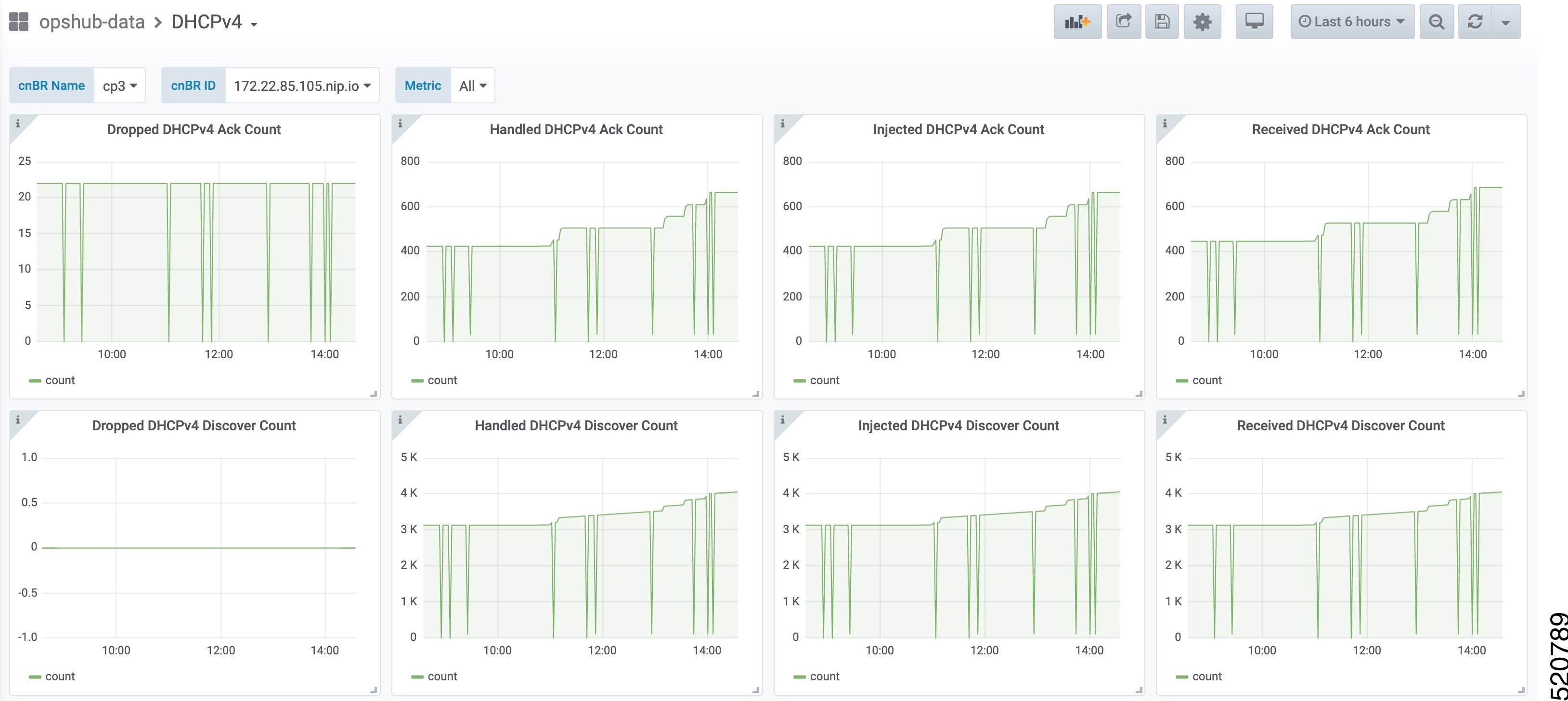
DHCPv4 dashboard displays statistics of the DHCP relay of IPv4. In all, there are 16 panels. The preceding picture shows only half the number of panels. Each panel represents the count of different states for different packet over time. There are four packet types for DHCPv4: Discover, Offer, Request, and Acknowledgment (Ack). The system processes each type of packet differently: Received, Dropped, Handled, and Injected. You can change the time span at the top-right corner. Currently, they show the count for the last six hours.
DHCP IPv6 Statistics
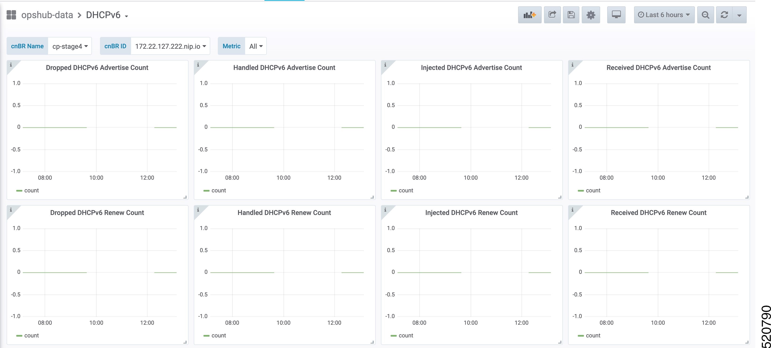
DHCPv6 dashboard displays statistics of the DHCP relay of IPv6. In all, there are 16 panels. The preceding picture shows only half the number of panels. Each panel represents the count of different states for different packet over time. There are four packet types for DHCPv6: Renew, Advertise, Request, and Reply. The system processes each type of packet differently: Received, Dropped, Handled, and Injected. You can change the time span at the top-right corner. Currently, they show the count for the last six hours.
PTP
Precision Time Protocol (PTP) is used to synchronize clocks throughout all cable networks. The Cisco cnBR cores and RPDs are managed by the Cisco cnBR, and runs an instance of the PTP client. To achieve time synchronization, the PTP client in Cisco cnBR and the PTP client in RPDs must synchronize their clocks to the same PTP primary clock. The Cable Modems (CMs) then synchronize their clock to the Cisco cnBR (and eventually to the PTP primary clock) through the DOCSIS timestamps provided by the RPD.
PTP allows creation of individual profiles for different scenarios. A profile is a specific selection of PTP configuration options that are selected to meet the requirements of a particular application. Cisco cnBR supports the PTP default profile.
To provide a high availability precision clock in the Cisco cnBR, two PTP primary clock sources can be configured in cnBR - a main PTP primary clock server and an alternate PTP primary clock server. Cisco cnBR synchronizes its clock to the best available PTP primary clock.
Some of the key parameters that are configured, or configurable, in the Cisco cnBR and RPD PTP client include:
-
PTP Domain
A PTP domain is a logical grouping of clocks that communicate with each other using the PTP protocol. A single computer network can have multiple PTP domains operating separately. For example, one set of clocks synchronized to one time scale and another set of clocks synchronized to another time scale. PTP can run over either Ethernet or IP, so a domain can correspond to a Local Area Network, or it can extend across a Wide Area Network.
In Cisco cnBR and RPD PTP client, the PTP domain is set during initial Cisco cnBR deployment. The PTP domain can be updated after deployment.
-
PTP Transport
In Cisco cnBR and RPD, the PTP transport is configured to use PTP over IPv4 in unicast mode. The PTP Transport mode is not configurable in Cisco cnBR PTP client. The PTP Transport mode is configurable in the RPD PTP client.
-
PTP Ports
A port can be configured to perform either fixed primary or secondary role, or can be configured to change its role dynamically. If no role is assigned to a port, it can dynamically assume a primary, passive, or secondary role, based on the Best Primary Clock Algorithm (BPCA), which is also known as Best Master Clock Algorithm (BMCA [RFCÂ 7273]).
Cisco cnBR and RPD support the PTP port secondary role. The Cisco cnBR PTP port role is not configurable. However, the RPD PTP port role is configurable, but it must be set to secondary role.
-
PTP Clock Mode
PTP Clock Mode can be configured as either of the following modes:
-
1-step clock mode: The PTP primary clock includes its timestamp in the synchronization message when the synchronization message is sent by the hardware. This mode requires hardware to insert the clock timestamp right before the synchronization message is sent through the wire.
-
2-step clock mode: The PTP primary clock sends its timestamp in a separate message after sending the synchronization message. This mode does not require hardware support, but the timestamp messages and the synchronization messages may arrive at the PTP clients out of order in some scenarios.
Cisco cnBR and RPD support the 1-step clock mode. The PTP Clock mode is not configurable.
-
Configure PTP
This table lists the features, the releases in which each feature was introduced, and gives a small description of each feature.
|
Feature Name |
Release Information |
Feature Description |
|---|---|---|
|
Support for redundant PTP primary clock for RPDs |
Cisco cnBR 21.3 |
This feature adds support for a redundant PTP primary clock for the Cisco cnBR and RPDs. This additional primary clock improves redundancy. |
|
Support for user configurable PTP intervals |
Cisco cnBR 21.3 |
This feature allows you to configure the intervals at which the Cisco cnBR sends PTP Announce, Sync, and Delay_Req packets. This feature allows for granular control over PTP activity in the network. |
|
Support for DSCP marking for Cisco cnBR PTP packets |
Cisco cnBR 21.3 |
This feature allows you to set the Differentiated Services Code Point for PTP packets. This feature enables you to set the priority for PTP packets in the network. |
You can configure the PTP client in the Cisco cnBR and RPD during the initial Cisco cnBR configuration using autodeployer.
Procedure
| Step 1 |
The top-level autodeployer configuration file that you use in the deployment of Cisco cnBR must include the configuration for the PTP client in the Cisco cnBR. The following table provides description of the PTP parameters, descriptions, and the required mandatory information.
|
|||||||||||||||||||||||||||||||||||||||||||||||||||||||||||||||||||||
| Step 2 |
The reference Service Group template must include the configuration of the PTP client in the RPD. Go through the following table for the detailed values. Configuration values for the SG Template
For more information on the listed parameters, go through the RPD documentation at https://www.cisco.com/c/en/us/td/docs/cable/cbr/configuration/guide/b-rpd-full-book-11/b-rpd-full-book-11_chapter_011.pdf. |
Example
-
Cisco cnBR PTP client-related parameters in the autodeployer top-level configuration file: // IPv4 address of PTP Primary Clock and alternate Primary clock servers, // and their respective Gateway server, in the top level config file. ptp : v4 : domain : 0 master: {'ip':"10.158.158.158", 'gw':"10.70.78.1"} alt-master: {'ip':"10.150.158.159", 'gw':"10.7.78.77"} dscp: 46 interval: {'announce': 1, 'delay-request': -1, 'sync': -1} //Specify the "SG template" that contains the RPD PTP Client parameters. SG : 'SG_4x4': 'sg_template.json'
Note
-
PTP does not support IP dual stack. Please configure either IPv4 or IPv6.
-
PTP primary IP must come with a PTP primary IP gateway. PTP alternate primary IP must come with a PTP alternate primary IP gateway.
-
The DSCP value must be same as that in the DSCP config on the ptp primary.
-
The interval value must follow the max interval restriction on the ptp primary.
-
If you do not configure the DSCP and interval parameters, the Cisco cnBR applies the following default values.
           dscp: 46
           interval: {'announce': 1, 'delay-request': -1, 'sync': -1}
-
-
RPD PTP client-related parameters in the SG_template: "rpdPtpCfg": { "dtiMode": "SlaveDtiMode", "domain": 44, "priority1": 128, "priority2": 255, "ptpClkProfileId": "00:00:00:00:00:00", "ptpPortCfg": [ { "adminState": "Up", "anncReceiptTimeout": 11, "cos": 6, "dscp": 47, "enetPortIndex": 1, "gateway": "10.70.78.1", "gatewayAlt": "10.7.78.77", "localPriority": 128, "logDelayReqInterval": -4, "logSyncInterval": -4, "masterAddr": "10.158.158.158", "masterAddrAlt": "10.150.158.23", "masterAdminState": "Up", "ptpPortIndex": 22, "unicastDuration": 300 } ] }
Update cnBR PTP Configuration using Autodeployer
You can update the Cisco cnBR PTP configuration using the Autodeployer.
Ensure that you have configured the Cisco cnBR PTP client during deployment, and the Cisco cnBR using the Autodeployer.
See Configure Cisco cnBR Using Autodeployer for more information.
Go through the following steps to update the PTP configuration:
Procedure
| Step 1 |
Locate the Autodeplyer configuration files used for the initial deployment and configuration of cnBR. This includes:
|
||
| Step 2 |
Update the PTP section of the top-level Autodeployer configuration file. |
||
| Step 3 |
Run the Autodeployer configuration script.
|
Update cnBR PTP Configuration using cnBR Manager
You can update the Cisco cnBR PTP configuration using the cnBR Manager.
Ensure that you have configured the Cisco cnBR PTP client during deployment and the Cisco cnBR using the Autodeployer. Also, ensure that the Cisco cnBR is added to the cnBR Manager.
To view and update the PTP configuration parameters, use the following procedure:
Procedure
| Step 1 |
On the Cisco Operations Hub, click the Cisco Operations Hub main menu button. |
| Step 2 |
Choose cnBR Manager > cnBRs to open the cnBR Clusters page. |
| Step 3 |
Click the name of the Cisco cnBR to open the cnBR Cluster Configuration page. |
| Step 4 |
Choose PTP from the drop-down list and edit the configuration using one of the following modes:
|
| Step 5 |
Configure the Cisco cnBR PTP client with either a single primary clock or with dual primary clocks. The following image shows the Cisco cnBR PTP client with a single primary clock. 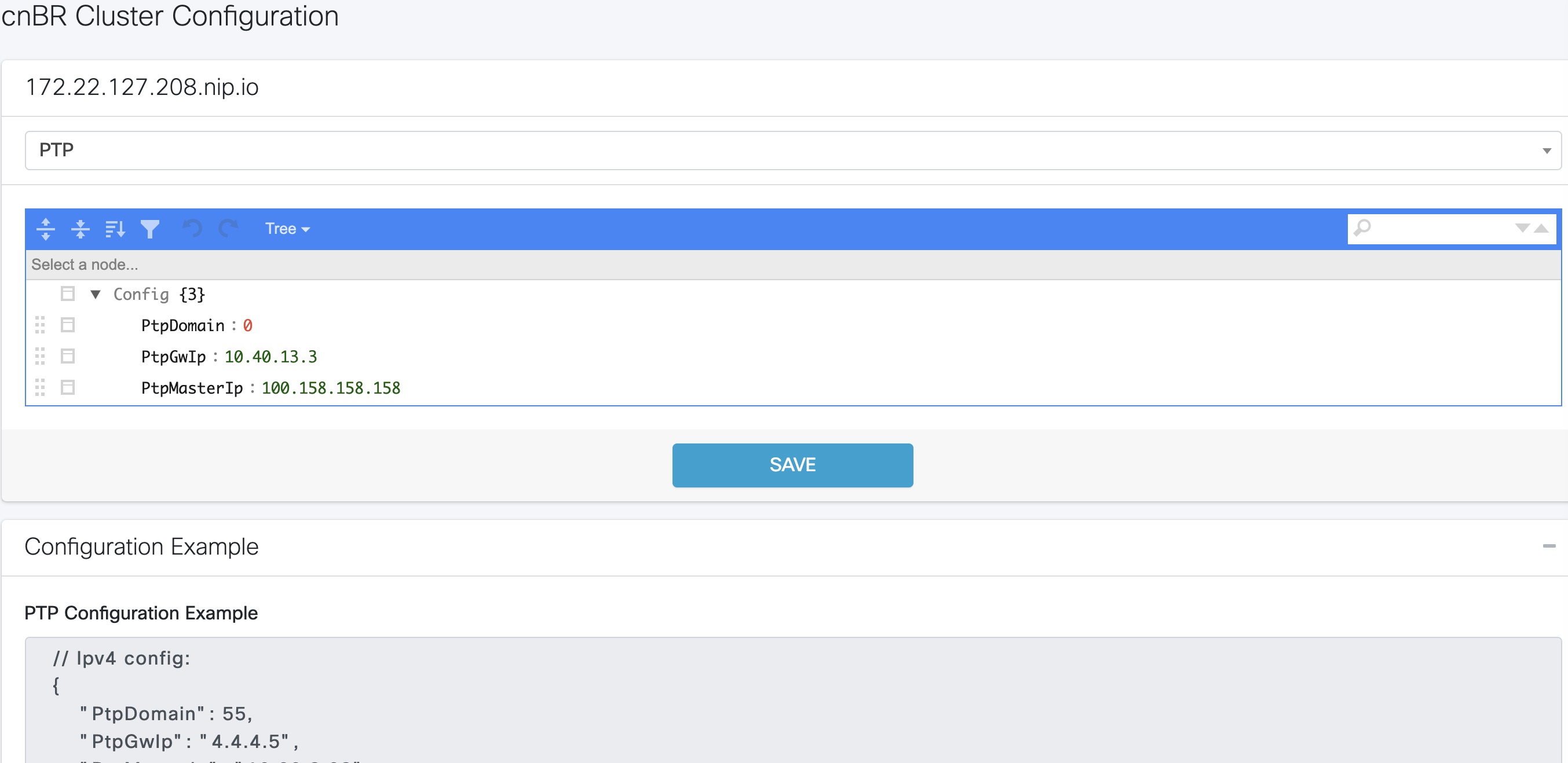 The following image shows the Cisco cnBR PTP client with dual primary clock. 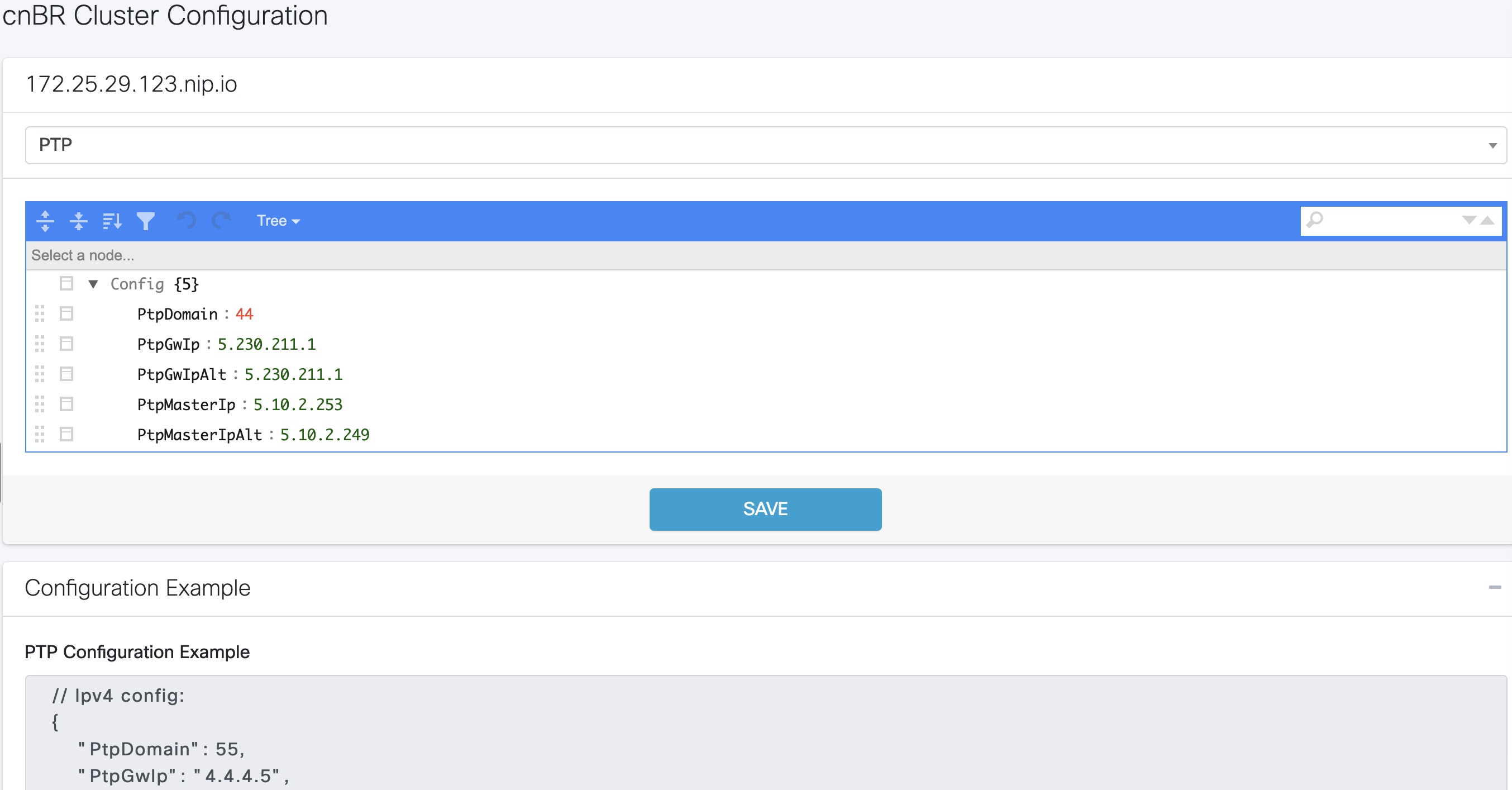 |
Update RPD PTP Configuration using Autodeployer
You can update the RPD PTP configuration using the Autodeployer. We recommend this method of updating the RPD PTP.
Ensure that you have configured the RPD PTP client during the deployment, and have configured Cisco cnBR using the Autodeployer.
See Configure Cisco cnBR Using Autodeployer for more information.
Procedure
| Step 1 |
Locate the complete set of Autodeplyer configuration files used in the initial deployment and configuration of cnBR. This includes:
|
||
| Step 2 |
Update the rpdPtpCfg section of the Service Group template. |
||
| Step 3 |
Run the Autodeployer configuration script.
|
Update RPD PTP Configuration using cnBR Manager
You can update the RPD PTP configuration using the cnBR Manager.
Ensure that you have configured the RPD PTP client during deployment, and have configured Cisco cnBR using the Autodeployer.
To view and update the RPD PTP configuration parameters, use the following procedure:
Procedure
| Step 1 |
On the Cisco Operations Hub, click the Cisco Operations Hub main menu button. |
| Step 2 |
Choose cnBR Manager > cnBRs to open the cnBR Clusters page. |
| Step 3 |
Click Import & Export cnBR to open the Export/Import page. |
| Step 4 |
On the Export cnBR Configuration pane, choose the Cisco cnBR that you want to update. |
| Step 5 |
Click Export to retrieve the current SG configuration of the selected Cisco cnBR. |
| Step 6 |
In the |
| Step 7 |
Save the updated file to the local disk. |
| Step 8 |
Update the SG configuration.
|
| Step 9 |
Delete the RPD and add the RPD again for the updated SG configuration to take effect. |
Monitor and Troubleshoot PTP
You can view the PTP status and its details on the PTP dashboard.
To view the PTP dashboard, use the following procedure:
Procedure
| Step 1 |
Enter the Cisco Operations Hub URL |
||
| Step 2 |
On the Cisco Operations Hub, click the Cisco Operations Hub main menu button. |
||
| Step 3 |
Choose Dashboard to open the Dashboard page. |
||
| Step 4 |
Click Find a Dashboard to open the search pane. |
||
| Step 5 |
Enter PTP in the Search dashboards by name field and click the PTP row. The PTP dashboard appears. 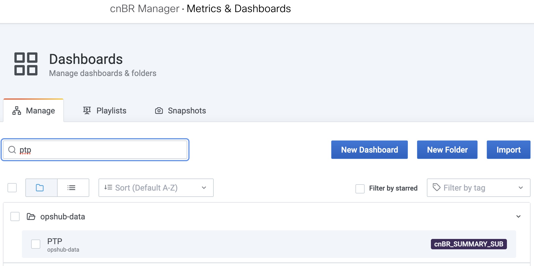
|
BGP Agent
The BGP Agent is a service in Cisco cnBR. It sets up BGP sessions with the SP router and installs or withdraws subscribed routes on the SP router while the subscribed devices (e.g. CM/CPE) are online.
The Cisco cnBR BGP Agent supports BGP version 4, includes address family IPv4 unicast, address family IPv6 unicast, and supports Graceful Restart.
Configure BGP Agent
You can perform the BGP Agent initial configurations through the Autodeployer Config file. See Configure Cisco cnBR Using Autodeployer for additional information.
After the initial setup, you can access BGP Agent configuration through the cnBR Manager. See instructions for Access BGP Agent Configuration.
Configuration Parameters
The table displays the BGP configuration parameters, their description, type and enforcement information
| Field Name | Description | Type | Enforcement |
|---|---|---|---|
| asNumber | BGP supports 2-byte AS numbers | 1 ~ 65535 | Required |
| ebgpMultihop | The maximum number of eBGP hops allowed | 0 ~ 255 | Required |
| ifname | BGP Agent interface name | String, length 1 ~ 255 | Required |
| neighbors | BGP peer; BGP uses TCP port 179 to create a TCP session with a peer | Required | |
| weight | Weight of BGP peers; if you configure two BGP IPv4/IPv6 peers, the upstream routes sent from these peers are accepted in the order of weight. Default: 100 | Unsigned integer | Optional |
| address | BGP peer IP/IPv6 address | String | Required |
| gateway | The gateway IP address if the BGP messages are transmitted to loopback interface on the SP router | String | Optional |
| gracefulRestart | BGP graceful restart parameters | Required | |
| enable | True, to enable the graceful restart BGP option and False, to disable it | Bool | Required |
| restartTime | Determines how long the peer routers wait to delete stale routes before a BGP open message is received | 1 ~ 3600 seconds | Required |
| stalePathTime | Determines how long a router waits before deleting stale routes after receiving an end of record (EOR) message from the restarting router | 1 ~ 3600 seconds | Required |
Graceful Restart
When a BGP router restarts, all its neighbors detect that the BGP router went down and has come up again. It results in the deletion and adding back of the BGP routes in the neighbors. The unnecessary recomputation of routes, called a "routing flap", causes issues on both the BGP and neighbor routers. Graceful Restart allows the system to preserve the routes during BGP restart, thus minimizing the negative effects of BGP restart.
BGP Agent Configuration
The Cisco cnBR BGP Agent allows easy modification of BGP Agent global configurations.
Access BGP Agent Configuration
Procedure
| Step 1 |
Log in to Cisco Operations Hub. |
| Step 2 |
On the Cisco Operations Hub, click the Cisco Operations Hub main menu button. |
| Step 3 |
Choose cnBR Manager > cnBRs to open the cnBR Clusters page. |
| Step 4 |
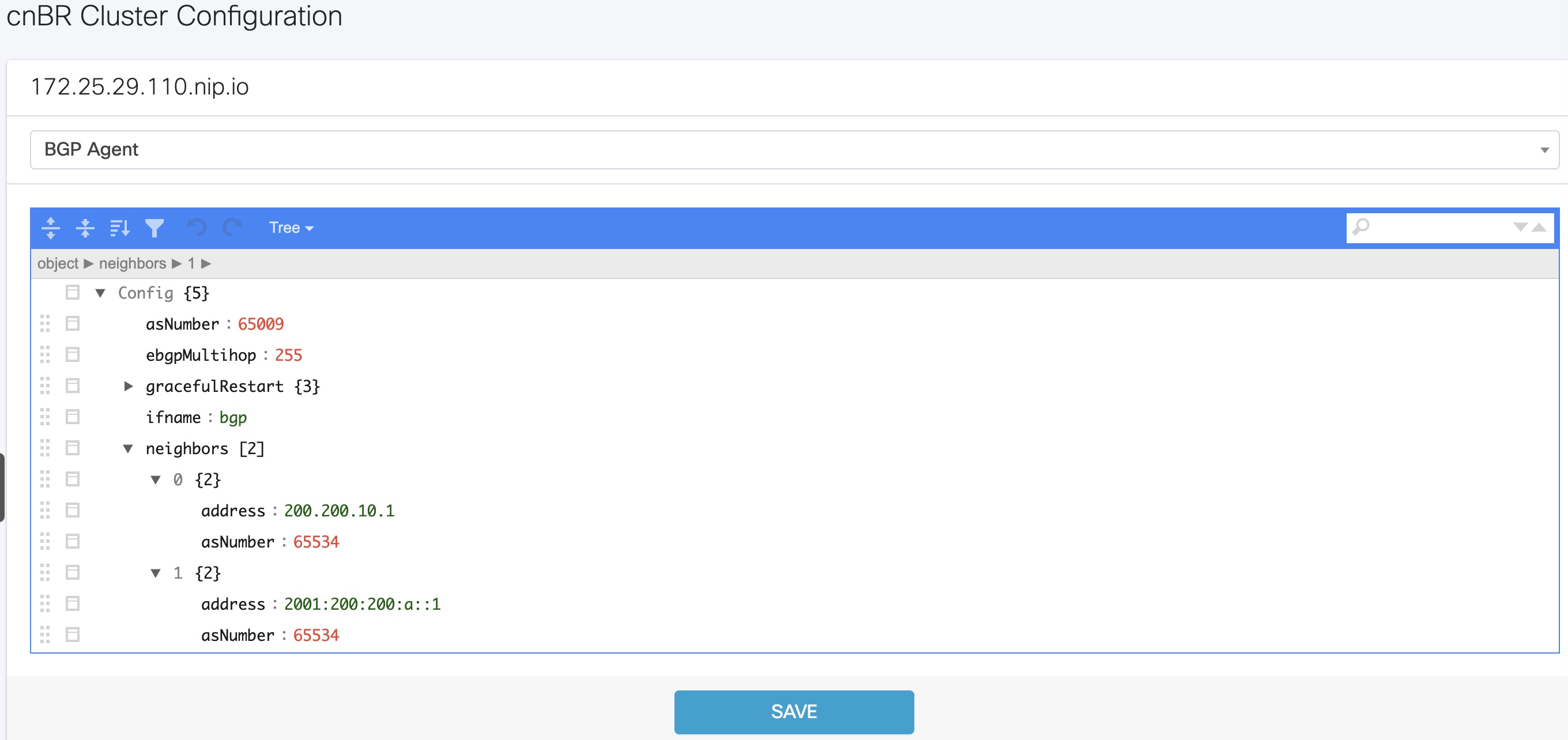
Click the name of the target Cisco cnBR to open the cnBR Cluster Configuration page. |
| Step 5 |
Choose BGP Agent from the drop-down list. |
Add BGP Neighbors
Procedure
| Step 1 |
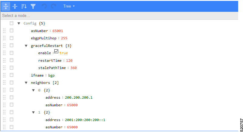
In the BGP Agent configurator, expand |
| Step 2 |
From the drop-down list, expand Append and select Object. 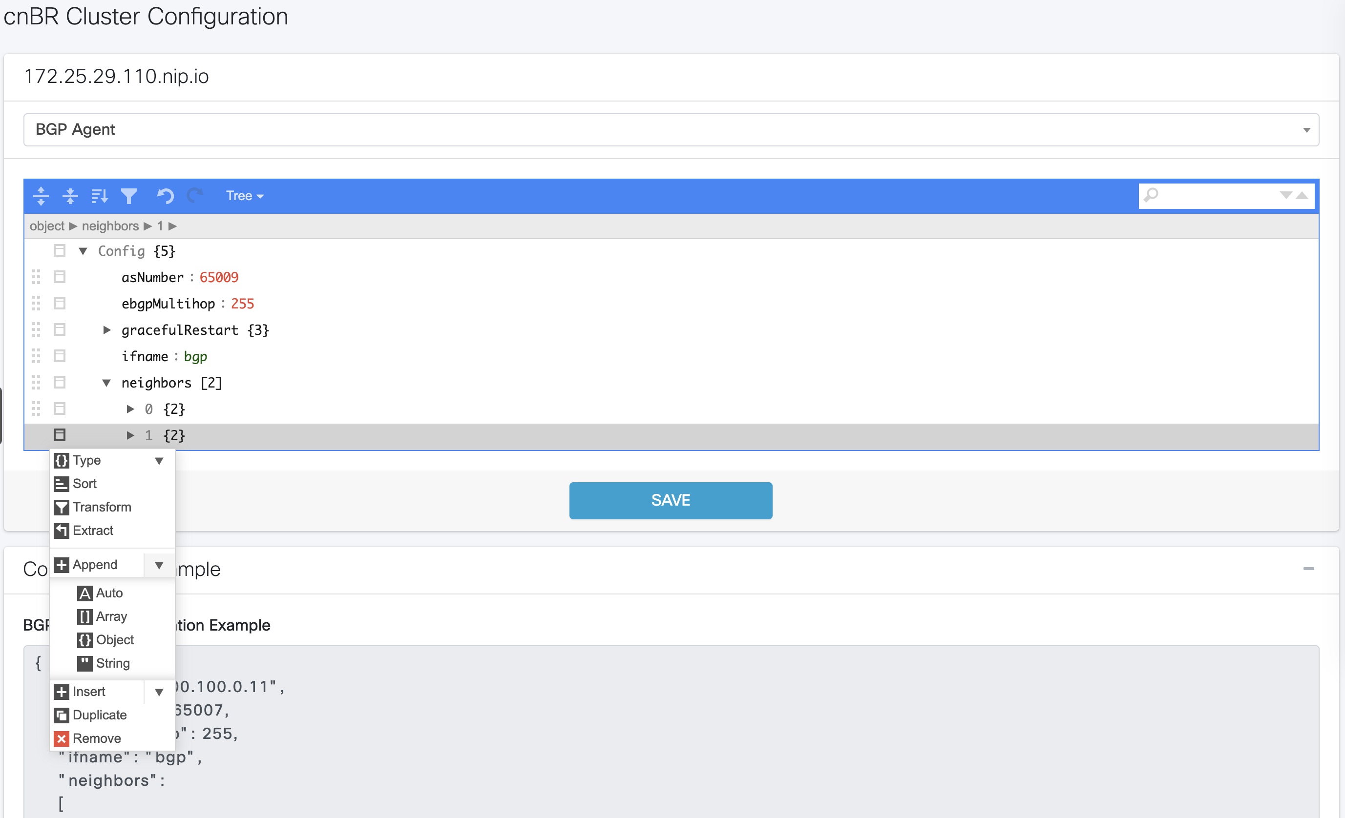 |
| Step 3 |
In the new object, click the edit box of the |
| Step 4 |
Choose Append from the drop-down list to create an object with two fields. 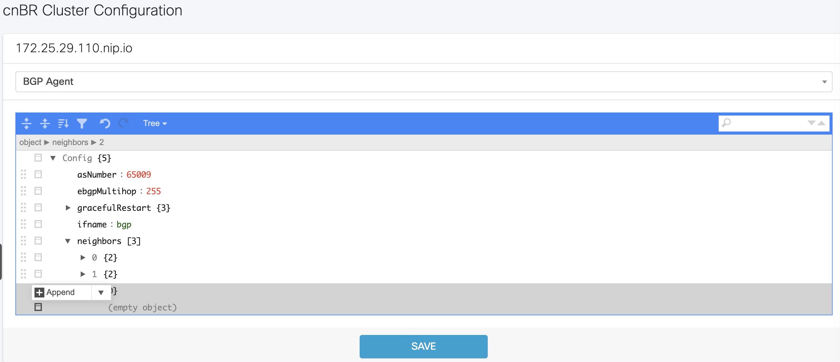 |
| Step 5 |
In the first field, enter  This image is not available in preview/cisco.com |
| Step 6 |
Click the edit box of the |
| Step 7 |
In the first field, enter |
| Step 8 |
Click Save. |
Delete BGP Neighbors
Procedure
| Step 1 |
In the BGP Agent configuration, expand all neighbor objects to locate the neighbor to delete. |
| Step 2 |
Select the edit box of the neighbor object to delete, then select Remove. |
| Step 3 |
Click Save. |
Get BGP Neighbors
BGP neighbor information is stored in the neighbors field in the BGP configurator.
BGP Agent Dashboard
The Cisco cnBR BGP Agent Dashboard provides visibility into the BGP IPv4 and IPv6 routes and operation.
Access BGP Agent Dashboard
Procedure
| Step 1 |
Log in to the Cisco Operations Hub. |
| Step 2 |
On the Cisco Operations Hub, click the Cisco Operations Hub main menu button. |
| Step 3 |
Choose Dashboard to open the Dashboard page. |
| Step 4 |
Click Find a Dashboard to open the search pane. |
| Step 5 |
Enter bgp in the Search dashboards by name field and click the BGP Agent row. |
| Step 6 |
Choose the desired Cisco cnBR from the cnBR Name drop-down list. The BGP Agent Dashboard of the desired Cisco cnBR appears. 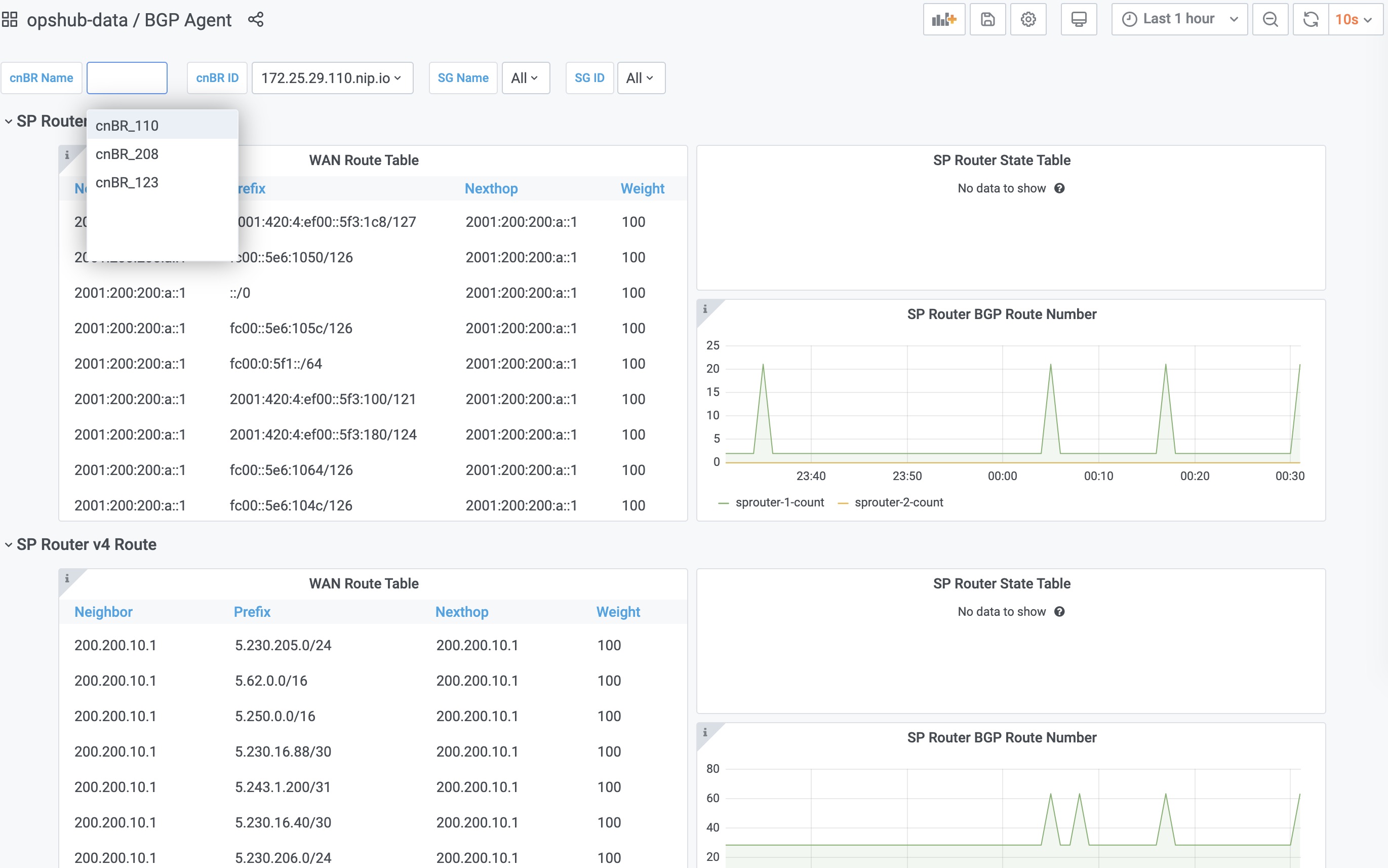 |
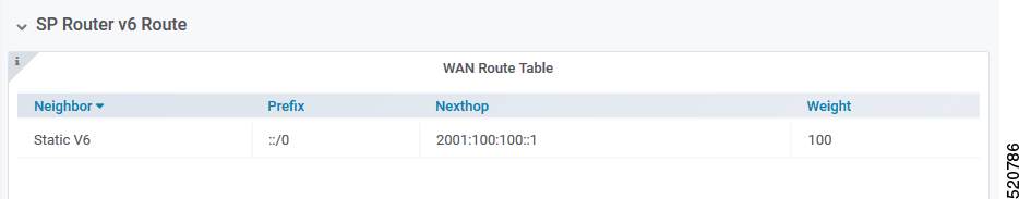
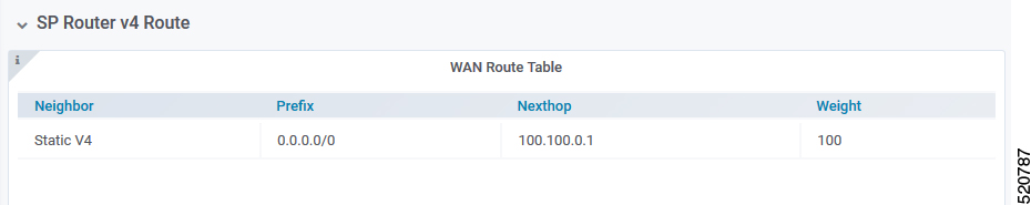
WAN Route Table
WAN Route Table displays the default routes generated by BGP Agent, and BGP routes received by the SP Router.
This image is not available in preview/cisco.com
The table dispalys the WAN Route Table parameters and their descriptions
| Name | Description |
|---|---|
| Neighbor | Neighbor IP address |
| Prefix | Network segment of route |
| Nexthop | IP address of next hop to get to destination |
| Weight | Weight parameter described in Configuration Parameters |
SP Router State Table
SP Router State Table displays the connection state between the BGP Agent and the SP router. The UP state indicates that the connection is established, and the DOWN state indicates the connection is not established.
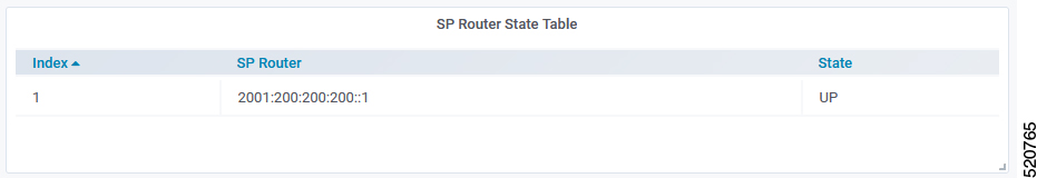
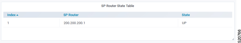
The following table dispalys the SP Router State parameters and their descriptions
| Name | Description |
|---|---|
| SP Router | The IP address of the SP Router |
| State | State of the connection between BGP Agent and SP Router |
BGP Route Table
BGP Route Table displays the BGP routes that is sent to the SP router to route packets from CM to the correct DP.
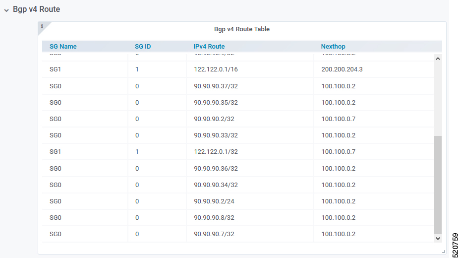
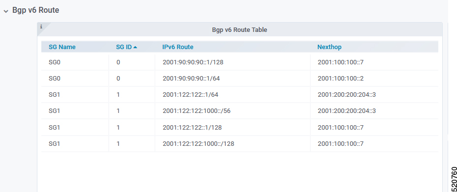
The following table lists the parameters with regard to the BGP Route Table
| Name | Description |
|---|---|
| SG Name | Service Group name corresponding to the route |
| SG ID | Service Group ID corresponding to the route |
| IP Route | Destination IP address |
| NextHop | Next IP address hop to get to destination |
BGP Route Number
BGP Route Number displays the number of BGP routes installed into the SP router over time.
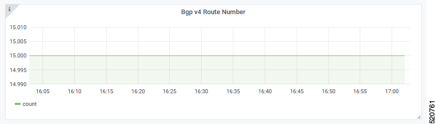
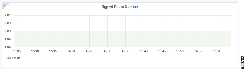
-
X-axis: Time
-
Y-axis: Number of BGP routes
BGP Route Rate
BGP Route Rate displays the rate of change of BGP routes over time.
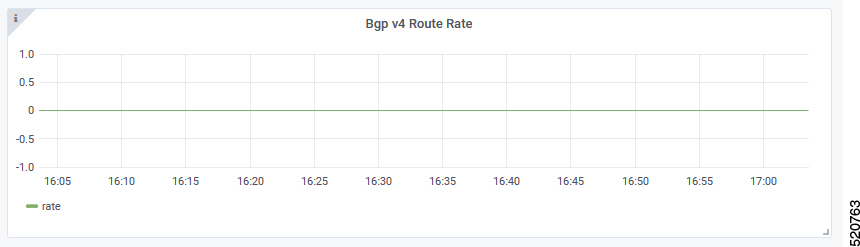
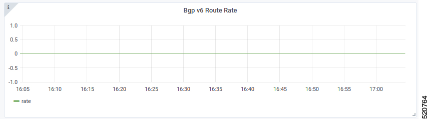
-
X-axis: Time
-
Y-axis: Change rate of BGP routes
L2VPN
The Cisco cnBR application emulates the Layer 2 virtual private network (L2VPN), when L2VPN devices across shared or public networks appear as computing devices that are directly connected to a switch device. Therefore, Layer 2 packets from one device can reach the other device without changes to the Layer 2 packet header, similar to the traditional Layer 2 Forwarding method.
Several tunneling protocols are used to implement L2VPN. Cisco cnBR supports the point-to-point mode L2VPN for the IEEE 802.1Q (dot1q) protocol.
For the dot1q L2VPN, Cisco cnBR adds one layer dot1q tag for the upstream packet and removes the tag at the receiving end.
Cisco cnBR supports both cable modem (CM) based L2VPN and service flow (SF) based L2VPN.
-
CM-based L2VPN: One CM can configure one L2VPN service. Primary upstream and primary downstream packets are encapsulated into a L2VPN tunnel.
-
Service flow-based L2VPN: One CM can configure up to four L2VPN services using the CM configure file TLV. A maximum of eight upstream SFs and eight downstream SFs are supported for each L2VPN service. The upstream classifier on the CM and downstream classifier on the Cisco cnBR router are used to classify different packets into L2VPN service flows.
Cisco cnBR supports the following types of L2VPN tunnel:
The table lists the L2VPN tunnels types and their detailed information
|
Tunnel Type |
CM-based |
SF-based |
|---|---|---|
|
dot1q |
|
|
Configure L2VPN
The dot1q L2VPN is implemented using the Cisco cnBR router with a Service Provider (SP) router.
SP routers are Cisco ASR 9000, Cisco ASR 1000, or Cisco Network Convergence System 5501.
The connection between the Cisco cnBR router and the SP router is supported by either the VxLAN mode or the VLAN mode.
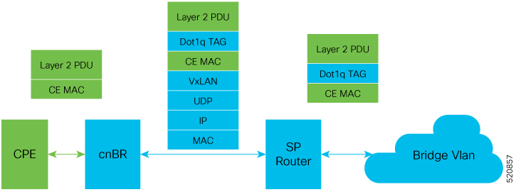
VxLAN Mode
The following image shows the dot1q L2VPN packet flow from CPE to the dot1q tunnel.
The following table summarizes the configuration that is required for the supported L2VPN types:
Supported L2VPN types and their required configuration
|
Tunnel Type |
CM-based |
SF-based |
|---|---|---|
|
dot1q |
|
|
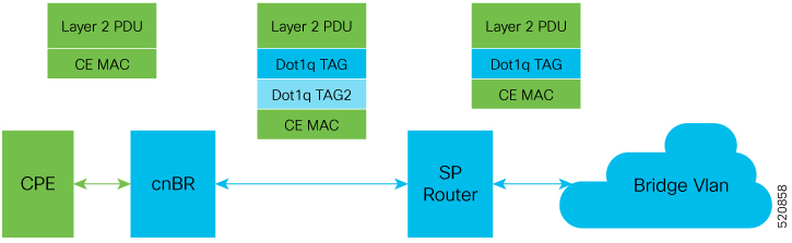
VLAN Mode
The following image shows the dot1q L2VPN packet flow from CPE to the dot1q tunnel.
The following table summarizes the configuration that is required for the supported L2VPN types:
The table lists the supported L2VPN types and their required configuration information
|
Tunnel Type |
CM-based |
SF-based |
|---|---|---|
|
dot1q |
|
|
Cisco cnBR L2VPN Configuration
For both CM-based and SF-based L2VPN, configure the L2VPN related VLAN or VxLAN that connects to the SP router. Use the cnBR Cluster Configuration window to configure the wiring.
For CM-based L2VPN, configure the static L2VPN map by using the REST API.
Procedure
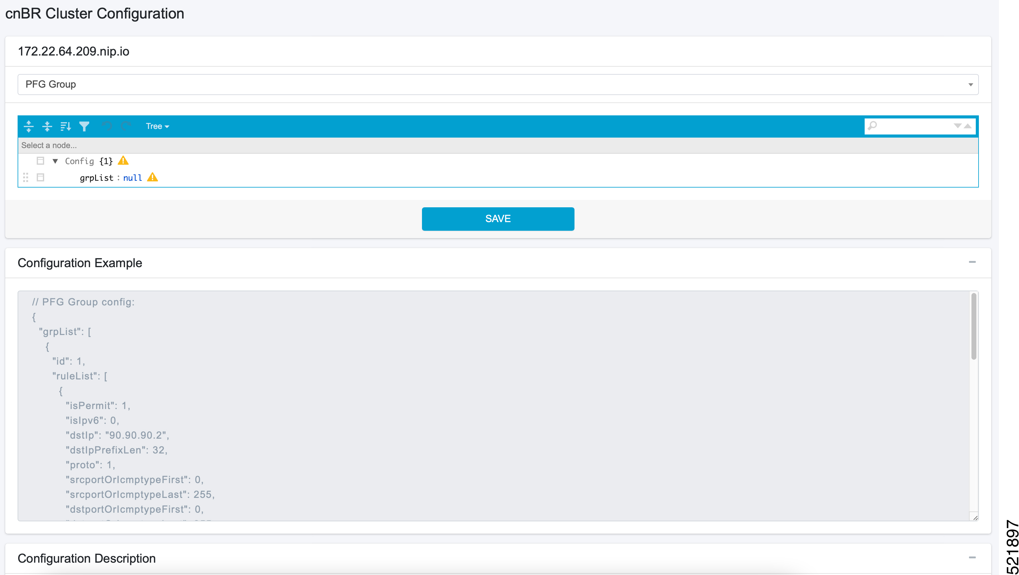
| Step 1 |
On the Cisco Operations Hub, click the Cisco Operations Hub main menu button. |
| Step 2 |
Choose cnBR Manager > cnBRs to open the cnBR Clusters page. |
| Step 3 |
Click the name of the target Cisco cnBR cluster to open the cnBR Cluster Configuration page. |
| Step 4 |
Select Wiring from the drop-down list. |
| Step 5 |
Update the configuration as required and click SAVE. |
Static Dot1q L2VPN
To configure a cable modem (CM) as dot1q CM-based L2VPN, upstream traffic (primary service flow) adds one-level dot1q tag.
Each L2VPN must have a different VLanId.
Procedure
| Step 1 |
On the Cisco Operations Hub, click the Cisco Operations Hub main menu button. |
| Step 2 |
Choose cnBR Manager > cnBRs to open the cnBR Clusters page. |
| Step 3 |
Click the name of the target Cisco cnBR cluster to open the cnBR Cluster Configuration page. |
| Step 4 |
Choose Layer 2 VPN from the drop-down list. |
| Step 5 |
Update the configuration as required and click SAVE. |
CM Configuration File TLV Definition
SF-based L2VPN depends on the CM configuration file TLV to set up L2VPN service, L2VPN service flow, and L2VPN classifier. For more details, see the CableLabs document: Business Services over DOCSIS Layer 2 Virtual Private Networks.
L3VPN
Layer 3 VPN (L3VPN) in Cisco cnBR is based on Multiprotocol Label Switching (MPLS) network. Cisco cnBR is at the Customer Edge (CE) and the service provider router is at the provider edge (PE), as shown in the following diagram.
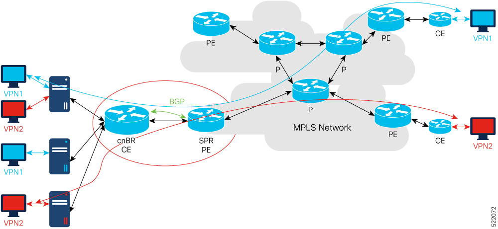
Cisco cnBR uses Border Gateway Protocol (BGP) to advertise Virtual Routing and Forwarding (VRF) (and global) routes and MPLS network uses MPLS to forward VPN packets on service provider backbones.
With L3VPN service, the system (Cisco cnBR and MPLS network) can enable cable mode (CM) or customer premises equipment (CPE) connect to host in the same VPN, and isolate CM/CPE from other VPN.
Configure L3VPN
To set up L3VPN, configure the following:
-
L3VPN global configuration
-
DHCP
Configure L3VPN Globally
day1.yaml), under l3vpn section, add two entries for voice and video. Following is a sample configuration:l3vpn:
- {"name" : "voice", "vlan" : 1050, "vpnRd" : "65000:1050"}
- {"name" : "video", "vlan" : 1051, "vpnRd" : "65000:1051"}
Configure L3VPN from Cisco Operations Hub
Use the following procedure to configure L3VPN globally through Cisco Operations Hub:
Procedure
| Step 1 |
Log in to Cisco Operations Hub. |
| Step 2 |
Click the Cisco Operations Hub main menu button on the top-left corner, choose cnBR Manager > cnBRs, and click Inventory. |
| Step 3 |
Choose the required Cisco cnBR core from the list. |
| Step 4 |
Choose the required cnBR, click Edit and click the Advanced tab. |
| Step 5 |
Choose L3 VPN from the drop-down list under Wiring. You can see the L3VPN configuration details. |
Configure SG DHCP in L3 Template
DHCP configuration depends on service groups (SG). Different SGs can have different VPN configurations. The following example shows the initial DHCP configuration of one SG.
For each SG, VPNs are configured under vrfList, whose name maps to L3VPN global configuration.
Relay policies are supported at the device type level.
{
          "dhcp": {
          "arpGlean": true,
          "arpProxy": true,
          "dhcpIfname": "cnr",
          "dhcpServers": [
               "10.70.70.12",
               "2001:10:70:70::12"
          ],
          "ipv6Lq": true,
          "mobilityScopes": [
               "1.1.1.1/24",
          ],
          "ndProxy": true,
          "v4Nets": [
               "91.91.91.1/24"
          ],
          "v6Nets": [
               "2001:91:91:91::1/64"
          ],
          "vrfList": [
               {
               "dhcpServers":["10.70.70.12","2001:10:70:70::12"],
               "name":"voice",
               "relayPolicies":[{"deviceClass":"HOST","giAddr":"93.93.93.1","linkAddr":"2001:93:93:93::1"}]
               "v4Nets":["92.92.92.1/24","93.93.93.1/24"],
               "v6Nets":["2001:92:92:92::1/64","2001:93:93:93::1/64"]
               },
               {
               "dhcpServers":["10.70.70.12","2001:10:70:70::12"],
               "name":"video",
               "v4Nets":["94.94.94.1/24"],
               "v6Nets":["2001:94:94:94::1/64"]
               }
          ],
          "savList": {
          "prefixes": null
          },
          "sgPeerIpv4": "201.201.201.1/24",
          "sgPeerIpv6": "2001:201:201:201::1/64"
     }
In this example, cable modems (CM) in the VPN voice get the 92.92.92.x address and the CPEs get 93.93.93.x address.
Configure SG DHCP in L3 Template from Cisco Operations Hub
Add the L3VPN configuration in the L3 template. Use the following sample configuration:
{
          "dhcp": {
          "arpGlean": true,
          "arpProxy": true,
          "dhcpIfname": "cnr",
          "dhcpServers": [
               "10.70.70.12",
               "2001:10:70:70::12"
          ],
          "ipv6Lq": true,
          "mobilityScopes": [
               "1.1.1.1/24",
          ],
          "ndProxy": true,
          "v4Nets": [
               "91.91.91.1/24"
          ],
          "v6Nets": [
               "2001:91:91:91::1/64"
          ],
          "vrfList": [
               {
               "dhcpServers":["10.70.70.12","2001:10:70:70::12"],
               "name":"voice",
               "relayPolicies":[{"deviceClass":"HOST","giAddr":"93.93.93.1","linkAddr":"2001:93:93:93::1"}]
               "v4Nets":["92.92.92.1/24","93.93.93.1/24"],
               "v6Nets":["2001:92:92:92::1/64","2001:93:93:93::1/64"]
               },
               {
               "dhcpServers":["10.70.70.12","2001:10:70:70::12"],
               "name":"video",
               "v4Nets":["94.94.94.1/24"],
               "v6Nets":["2001:94:94:94::1/64"]
               }
          ],
          "savList": {
          "prefixes": null
          },
          "sgPeerIpv4": "201.201.201.1/24",
          "sgPeerIpv6": "2001:201:201:201::1/64"
     }
Configure BGP Agent for L3VPN
In the initial-configuration YAML file (day1.yaml), add the BGP agent configration. Following is a sample configuration:
yaml
bgpagent :
    asn : 65002
    max_hops : 255
    # to set bgpagent work at loopback mode, uncomment below 2 lines and set IP address for them
    # loaddr : ['1.1.1.1', '1.1.1.2']
    # loaddrv6 : ['2001:1:1:1::1', '2001:1:1:1::2']
    restart-time : 120
    stale-path-time: 360
    neighbors :
      - {'address' :'201.201.201.1', 'asn':65000}
Configure BGP Agent from Cisco Operations Hub
Use the following procedure to configure BGP Agent through Cisco Operations Hub:
SUMMARY STEPS
- Log in to Cisco Operations Hub.
- Click the Cisco Operations Hub main menu button on the top-left corner, choose cnBR Manager > cnBRs, and click Inventory.
- Choose the required Cisco cnBR core from the list.
- Choose the required cnBR, click Edit and click the Advanced tab.
- Choose BGP Agent from the drop-down list under Wiring.
DETAILED STEPS
| Command or Action | Purpose | |
|---|---|---|
| Step 1 |
Log in to Cisco Operations Hub. |
|
| Step 2 |
Click the Cisco Operations Hub main menu button on the top-left corner, choose cnBR Manager > cnBRs, and click Inventory. |
|
| Step 3 |
Choose the required Cisco cnBR core from the list. |
|
| Step 4 |
Choose the required cnBR, click Edit and click the Advanced tab. |
|
| Step 5 |
Choose BGP Agent from the drop-down list under Wiring. |
You can see the BGP Agent configuration details. |
Example of Service Provider Configuration
Example for NCS-55A1
VRF definition
vrf video
 rd 65000:1051
 address-family ipv4 unicast
  import route-target
   65000:1051
  !
  export route-target
   65000:1051
  !
 !
 address-family ipv6 unicast
  import route-target
   65000:1051
  !
  export route-target
   65000:1051
  !
 !
!
vrf voice
 rd 65000:1050
 address-family ipv4 unicast
  import route-target
   65000:1050
  !
  export route-target
   65000:1050
  !
 !
 address-family ipv6 unicast
  import route-target
   65000:1050
  !
  export route-target
   65000:1050
  !
 !
!
WAN Sub-interface for Each VRF
interface FortyGigE0/0/0/5.1050
 vrf voice
 ipv4 address 201.201.201.1 255.255.255.0
 ipv6 nd prefix default no-adv
 ipv6 nd suppress-ra
 ipv6 address 2001:201:201:201::1/64
 encapsulation dot1q 1000 second-dot1q 1050
!
interface FortyGigE0/0/0/5.1051
 vrf video
 ipv4 address 201.201.201.1 255.255.255.0
 ipv6 nd prefix default no-adv
 ipv6 nd suppress-ra
 ipv6 address 2001:201:201:201::1/64
 encapsulation dot1q 1000 second-dot1q 1051
!
BGP Configuration
router bgp 65000
 bgp router-id 1.1.1.1
 address-family ipv4 unicast
 !
 address-family vpnv4 unicast
 !
 address-family ipv6 unicast
 !
 address-family vpnv6 unicast
 !
 neighbor 201.201.201.198
  remote-as 65002
  bfd fast-detect
  bfd multiplier 3
  bfd minimum-interval 100
  address-family ipv4 unicast
   route-policy pass-all in
   route-policy pass-all out
  !
  address-family ipv6 unicast
   route-policy pass-all in
   route-policy pass-all out
  !
 !
 neighbor 201.201.201.199
  remote-as 65002
  bfd fast-detect
  bfd multiplier 3
  bfd minimum-interval 100
  address-family ipv4 unicast
   route-policy pass-all in
   route-policy pass-all out
  !
  address-family ipv6 unicast
   route-policy pass-all in
   route-policy pass-all out
  !
 !
 vrf video
  address-family ipv4 unicast
   label mode per-vrf
  !
  address-family ipv6 unicast
   label mode per-vrf
  !
  neighbor 201.201.201.198
   remote-as 65002
   address-family ipv4 unicast
    route-policy pass-all in
    route-policy pass-all out
   !
   address-family ipv6 unicast
    route-policy pass-all in
    route-policy pass-all out
   !
  !
  neighbor 201.201.201.199
   remote-as 65002
   address-family ipv4 unicast
    route-policy pass-all in
    route-policy pass-all out
   !
   address-family ipv6 unicast
    route-policy pass-all in
    route-policy pass-all out
   !
  !
 !
 vrf voice
  address-family ipv4 unicast
   label mode per-vrf
  !
  address-family ipv6 unicast
   label mode per-vrf
  !
  neighbor 201.201.201.198
   remote-as 65002
   address-family ipv4 unicast
    route-policy pass-all in
    route-policy pass-all out
   !
   address-family ipv6 unicast
    route-policy pass-all in
    route-policy pass-all out
   !
  !
  neighbor 201.201.201.199
   remote-as 65002
   address-family ipv4 unicast
    route-policy pass-all in
    route-policy pass-all out
   !
   address-family ipv6 unicast
    route-policy pass-all in
    route-policy pass-all out
   !
  !
 !
IPv6
The following table provides description of the various features and their release information
|
Feature Name |
Release |
Feature Description |
|---|---|---|
|
IPv6 WAN Protocols |
Cisco cnBR 21.1 |
Allows you to use WAN protocols over IPv6. The WAN protocols consist of IPv6 BGP Agent, IPv6 DHCP Relay Agent and Proxy, and IPv6 DMIC. |
Cisco cnBR supports IPv6 protocol when communicating with the following network devices:
-
Cable Modem (CM)
-
Customer Premise Equipment (CPE)-Equipment that is connected to the CM at the customer premise.
Note |
Cisco cnBR supports dual-stack IPv4 and IPv6 protocols (It supports both IPv4 and IPv6 addresses at the same time). |
Cisco cnBR supports WAN protocols over IPv6, along with CIN protocols. The WAN protocols consist of IPv6 BGP Agent, IPv6 DHCP Relay Agent and Proxy, and IPv6 DMIC. In the current network topology, both CIN and WAN networks are connected to the SP router through a layer 2 switch.
Configure IPv6 WAN
Configure Service Provider router BGP WAN, which includes BGP routing display, Wiring configuration, layer 3 (L3) configuration, SG template configuration, and DMIC configuration.
Following are a few sample configurations, which may be different for each vendor router. The current topology must have a Layer 2 switch between the SP router and Cisco cnBR.
Configure BGP WAN
```
interface Bundle-Ether1.1001
 description WAN-for-cnbr-mn
 mtu 9216
 ipv4 address 200.200.9.1 255.255.255.0
 ipv4 address 100.100.9.1 255.255.255.0 secondary
 ipv6 address 2001:100:100::9:1/112
 ipv6 address 2001:200:200::9:1/112
 encapsulation dot1q 1001
!
router bgp 65534
 bgp router-id <rtr-id>
 address-family ipv6 unicast
  aggregate-address fd26:ba99:aae:944::/64 summary-only
  aggregate-address fd26:ba99:aae:2244::/96 summary-only
  aggregate-address fd26:ba99:aae:2344::/96 summary-only
  aggregate-address fd26:ba99:aae:2444::/64 summary-only
  redistribute connected
  redistribute static
 !
 neighbor-group ibgp
  remote-as 65534
  update-source Loopback0
  address-family ipv6 unicast
   route-policy pass-all in
   route-policy pass-all out
  !
 neighbor 2001:200:200::9:2
  remote-as 65009
  ebgp-multihop 255
  description "For cnbr-mn eBGP"
  address-family ipv6 unicast
   route-policy pass-all in
   route-policy pass-all out
  !
 !
 neighbor 2001:200:200::9:3
  remote-as 65009
  ebgp-multihop 255
  description "For cnbr-mn eBGP"
  address-family ipv6 unicast
   route-policy pass-all in
   route-policy pass-all out
  !
```
BGP Routing Display
```
SP RTR: show bgp ipv6 unicast summary
BGP router identifier 172.2.44.1, local AS number 65534
BGP generic scan interval 60 secs
Non-stop routing is enabled
BGP table state: Active
Table ID: 0xe0800000   RD version: 8842309
BGP main routing table version 8842309
BGP NSR Initial initsync version 8 (Reached)
BGP NSR/ISSU Sync-Group versions 0/0
BGP scan interval 60 secs

BGP is operating in STANDALONE mode.


Process       RcvTblVer   bRIB/RIB   LabelVer  ImportVer  SendTblVer  StandbyVer
Speaker         8842309    8842309    8842309    8842309     8842309           0

Neighbor        Spk    AS MsgRcvd MsgSent   TblVer  InQ OutQ  Up/Down  St/PfxRcd
2001:200:200::9:2
                  0 65009 2627876   89050  8842309    0    0 19:28:38         80
2001:200:200::9:3
                  0 65009 2625705   87694  8842309    0    0 19:25:52         80

```
Configure Wiring
wiring :
    bgp-agent-if:
       v4 : ['200.200.9.2', '200.200.9.3']
       v6 : ['2001:200:200::9:2', '2001:200:200::9:3']
    sg-peer: {'v4':'200.200.9.1', 'v6':'2001:200:200::9:1'}
    vlan :
       cnbr-wan-ifname: 'Ethernet0/0/0'
       overlay-wan-vlan: 1001
       overlay-cin-vlan: 1002
bgpagent :
    asn : 65009
    max_hops : 255
    restart-time : 120
    stale-path-time: 360
    neighbors :
       - {'address' :'200.200.9.1', 'asn':65534}
       - {'address' :'2001:200:200::9:1', 'asn':65534}

tftpProxy:
    v4 : ['200.200.9.1']
    v6 : ['2001:200:200::9:1']
SP Router Redundancy Configuration:
spr :
    sp-router-redundancy-mode : "active-active"
    sp-routers :
       - {'bgp-peer' :'200.200.9.1', "sg-peer": "200.200.9.1", "router-id": "200.200.9.1", "cin-gateway": "100.100.9.1", "ptp-gateway": "100.100.9.1"}
       - {'bgp-peer' :'2001:200:200::9:1'}
       - {'bgp-peer' :'200.200.9.250', "sg-peer": "200.200.9.250", "router-id": "200.200.9.250", "cin-gateway": "100.100.9.250", "ptp-gateway": "100.100.9.250"}
Configure Layer 3
{
  "dhcp": {
    "arpGlean": true,
    "arpProxy": true,
    "dhcpIfname": "cnr",
    "dhcpServers": [
      "1.2.2.91",
      "fd26:ba99:aae:102::2:91"
    ],
    "ipv6Lq": true,
    "mobilityScopes": [
      "1.1.1.1/24",
      "2001::a/88"
    ],
    "ndGlean": false,
    "ndProxy": true,
    "relayPolicies": [
     {
         "deviceClass": "CM",
         "giAddr": "9.44.6.2",
         "linkAddr": "fd26:ba99:aae:0944:6::1",
         "v4ServerIp": "1.2.2.91",
         "v6serverip": "fd26:ba99:aae:102::2:91"
      },
      {
          "deviceClass": "HOST",
          "giAddr": "24.44.6.2",
          "linkAddr": "fd26:ba99:aae:0944:6::1",
          "v4ServerIp": "1.2.2.91",
    "v6ServerIp": "fd26:ba99:aae:102::2:91"
      }
    ],
    "relayModeV4": 0,
    "relayModeV6": 0,
    "v4Nets": [
      "9.44.6.2/24",
      "24.44.6.2/24"
    ],
    "v6Nets": [
      "FD26:BA99:AAE:944:6::1/80",
      "FD26:BA99:AAE:2444:6::1/80"
    ]

  },
  "spRouterName": "NCS-55A1",
  "savList": {
    "prefixes": null
  },
  "sgPeerIpv4": "100.100.6.1/24",
  "sgPeerIpv6": "2001:100:100::6:1/112",
  "ptp-mac-addr": "20:19:06:13:15:43"
}
Configure SG Template
The ipInit can be dual-stack, IPv6 only, or IPv4 only. The following is an example of the relevant subsection of the SG template:
 "md": [
        {
            "adminState": "Up",
            "cmInitChanTimeout": 60,
            "dataBackoff": {
                "end": 5,
                "start": 3
            },
	    "disableDocsis31": false,
            "idInSg": 0,
	    "ipInit": "dual-stack",
            "mac": "00:23:09:73:47:a5",
Configure DMIC
Dynamic Shared Secret that enables service providers to provide higher levels of security for their data-over-cable service interface specifications (DOCSIS) cable networks. This feature uses randomized, single-use shared secrets to verify the DOCSIS configuration files, which are downloaded to each cable modem.
Following is the L3 configuration for Dynamic Message Integrity Check (DMIC):
{
  "dhcp": {
    "arpGlean": true,
    "arpProxy": true,
    "dhcpIfname": "cnr",
    "dhcpServers": [
      "1.2.2.91",
      "fd26:ba99:aae:102::2:91"
    ],
    "dynamicSecret": true,
    "ipv6Lq": true,
Cisco cnBR as DHCP Relay Agent
In a Cisco cnBR system, cable modems and some of the associated CPEs acquire IP addresses from a DHCP server in the network. These cable modems, their associated CPEs, and the DHCP server are not on the same physical network. In this scenario, Cisco cnBR acts as a DHCP relay agent to relay all requests and replies between the clients (CM and CPE) and the DHCP server. The DHCP relay agent in Cisco cnBR supports both IPv4 and IPv6 addressing.
Cisco cnBR supports CMs and CPEs operating in IPv4, IPv6, and dual-stack modes.
When CMs operate in the IPv6 mode, especially only in the IPv6 mode, configure the TFTP server and operate it in the IPv6 mode. This configuration allows the CMs to connect to the TFTP server in IPv6 mode and download their CM configuration file.
Note |
DHCP messages from RPDs does not reach the DHCP relay agent in the Cisco cnBR router. These DHCP messages from RPDs can reach the DHCP server in the CIN without using the DHCP relay agent in Cisco cnBR. |
Configure DHCP Services
Initially, you can configure the DHCP relay services using the Autodeployer script, or by importing the Cisco cnBR configuration YAML file to the desired Cisco cnBR through the Cisco Operations Hub. The imported configuration file overwrites the existing configuration and activates the new configuration. Following is an example of the DHCP relay service configuration:
```
"Dhcp":
    {
        "ArpGlean":true,
        "ArpProxy":true,
        "ipv4Lq": false,
        "NdGlean":true,
        "NdProxy":true,
        "ipv6Lq":false,
        "dhcpServers":["80.80.80.3",
                       "81.81.81.3",
                       "2001:80:80:80::3",
                       "2001:81:81:81::3"
        ],
        "V4Nets":["90.90.90.1/24",
                  "91.91.91.1/24",
                  "92.92.92.1/24"
        ],
        "V6Nets":["2001:90:90:90::1/64",
                  "2001:91:91:91::1/64",
                  "2001:92:92:92::1/64"
        ],
        "RelayPolicies":[
          {"deviceClass": "HOST",
          "v4serverip": "80.80.80.3",
          "v6serverip": "2001:80:80:80::3",
          "giaddr": "90.90.90.1",
          "linkaddr": "2001:90:90:90::1"
          },
          {"deviceClass": "STB",
          "v4serverip": "81.81.81.3",
          "v6serverip": "2001:81:81:81::3",
          "giaddr": "91.91.91.1",
          "linkaddr": "2001:91:91:91::1"
          },
          {"deviceClass": "PS",
          "giaddr": "92.92.92.1",
          "linkaddr": "2001:92:92:92::1"
          },
          {"deviceClass": "EROUTER",
          "v4serverip": "80.80.80.3",
          "v6serverip": "2001:80:80:80::3",
          },
          {"deviceClass": "DVA",
          "giaddr": "90.90.90.1",
          "linkaddr": "2001:90:90:90::1"
          },
          {"deviceClass": "MTA",
          "giaddr": "91.91.91.1",
          "linkaddr": "2001:91:91:91::1"
          }
        ],
        "mobilityScopes":["90.90.90.1/24",
                          "91.91.91.1/24",
                          "92.92.92.1/24",
                          "2001:90:90:90::1/64",
                          "2001:91:91:91::1/64",
                          "2001:92:92:92::1/64"
        ]
    }
```
For more details, see DHCP Relay Service.
Cisco cnBR IPv6 CIN
From Cisco cnBR 20.4 onwards, Converged Interconnect Network (CIN) is supported over IPv6. CIN enables you to build a robust, flexible, and scalable network to interconnect the CCAP-Core and RPDs in a solution topology. You can provision RPD with IPv6 to communicate with cnBR ccap-core through IPv6.
The GCP, PTP, and L2TP protocol will be running over IPv6. You need to configure end-to-end CIN network from RPDs to SPR, and Cisco cnBR must be configured to support it. You also need to provision the RPDs to support IPv6.
Configure cnBR IPv6 CIN
Complete the following steps to configure Cisco cnBR IPv6 CIN:
Procedure
| Step 1 |
Configure the SP router CIN network interface with IPv6 address. |
| Step 2 |
SG template configuration masterAddr to PTP primary v6 address in
rpdPtpCfg section of SG
template: |
RIP
Routing Information Protocol (RIP) is used in small to medium TCP/IP networks. It uses a distance-vector algorithm to calculate routes. The RIP uses broadcast UDP data packets to exchange the routing information. Cisco cnBR can advertise the default network to the CPE devices running RIP, and collect the routing information updated by the CPE device.
Among the RIP version 2 features, Cisco cnBR supports plain text and message digest algorithm 5 (MD5) authentication, route summarization, classless interdomain routing (CIDR), and variable-length subnet masks (VLSMs). Only RIPv2 packets are sent and received.
Authentication Mode in RIP
Cisco cnBR supports two modes of authentication on RIP:
-
Simple authentication: Uses a plaintext password in every RIPv2 packet.
-
Message digest algorithm 5 (MD5) authentication: MD5 authentication pads digest information to each RIPv2 packet based on the packet content and preconfigured passwords. The key chain structure maintains passwords, which determines if a key can be used or valid.
Configure RIP
You can configure RIP on Cisco cnBR during the initial configuration using the Autodeployer.
The Autodeployer configuration file includes the following RIP configuration fields.
|
Field Name |
Description |
Mandatory |
|---|---|---|
|
enable |
Shows whether RIP is enabled on Cisco cnBR. |
Yes |
|
passive-mode |
Shows whether RIP works in passive mode. Default is |
No |
|
update-timer |
RIP update-timer in seconds. Default value is 30. |
No |
|
invalid-timer |
RIP invalid-timer in seconds. Default value is 180. |
No |
|
holddown-timer |
RIP hold-down timer in seconds. Default value is 180. |
No |
|
ripAuthMode |
RIP authentication mode. Default is |
No |
|
ripSimplePswd |
RIP simple authentication password. |
Yes, if ripAuthMode is simple. |
|
keychain |
RIP md5 authentication keychain. |
yes if ripAuthMode is md5. |
The keychain is a list of key items and each item must contain the following attributes:
|
Field Name |
Description |
Mandatory |
|---|---|---|
|
KeyID |
ID for each individual key. |
Yes |
|
KeyString |
Key phrase content. |
Yes |
|
algorithm |
Hash algorithm used by the key. Currently, supports only md5. |
No |
|
sendlifetime |
Time-interval to send keys. |
No |
|
acceptlifetime |
Time-interval to accept incoming keys. |
No |
Following is an example of the RIP configuration, as part of the Autodeployer configuration:
rip :
     enable : 'false'
     update-timer : 30
     invalid-timer : 180
     holddown-timer : 180
     passive-mode : 'false'
     ripAuthMode : "md5"
     keychain:
         - {'key-id': 10, 'algorithm': "md5", 'accept-lifetime': { "start": "1970-01-01T00:00:00Z07:00",
            "end": "2022-01-02T15:04:05Z07:00" }, 'send-lifetime': { "start": "1970-01-01T00:00:00Z07:00",
            "end": "2022-01-02T15:04:05Z07:00" }
Update RIP Configuration using cnBR Manager
You can also update the RIP configuration using the cnBR Manager from the Cisco Operations Hub. Use the following procedure:
SUMMARY STEPS
- Log in to Cisco Operations Hub.
- Click the Cisco Operations Hub main menu button on the top-left corner, choose cnBR Manager > cnBRs, and click Inventory.
- Choose the required Cisco cnBR core from the list.
- Choose the required cnBR, click Edit and click the Advanced tab.
- Choose RIP from the drop-down list under Wiring.
DETAILED STEPS
| Command or Action | Purpose | |
|---|---|---|
| Step 1 |
Log in to Cisco Operations Hub. |
|
| Step 2 |
Click the Cisco Operations Hub main menu button on the top-left corner, choose cnBR Manager > cnBRs, and click Inventory. |
|
| Step 3 |
Choose the required Cisco cnBR core from the list. |
|
| Step 4 |
Choose the required cnBR, click Edit and click the Advanced tab. |
|
| Step 5 |
Choose RIP from the drop-down list under Wiring. |
You can see the RIP configuration details. |


 Feedback