Alarms for the Cisco ISA 3000

You can configure the alarm system on a Cisco ISA 3000 device to alert you when undesirable conditions occur.

About Alarms

You can configure the ISA 3000 to issue alarms for a variety of conditions. If any conditions do not match the configured settings, the system triggers an alarm, which is reported by way of LEDs, syslog messages, SNMP traps, and through external devices connected to the alarm output interface. By default, triggered alarms issue syslog messages only.

You can configure the alarm system to monitor the following:
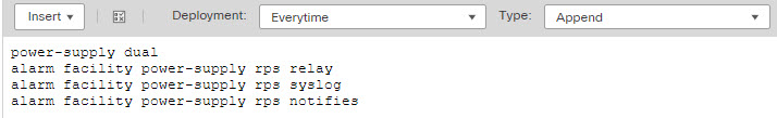
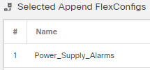
  • Power supply.

  • Primary and secondary temperature sensors.

  • Alarm input interfaces.

The ISA 3000 has internal sensors plus two alarm input interfaces and one alarm output interface. You can connect external sensors, such as door sensors, to the alarm inputs. You can connect external alarm devices, such as buzzers or lights, to the alarm output interface.

The alarm output interface is a relay mechanism. Depending on the alarm conditions, the relay is either energized or de-energized. When it is energized, any device connected to the interface is activated. A de-energized relay results in the inactive state of any connected devices. The relay remains in an energized state as long as alarms are triggered.

For information about connecting external sensors and the alarm relay, see Cisco ISA 3000 Industrial Security Appliance Hardware Installation Guide.

Alarm Input Interfaces

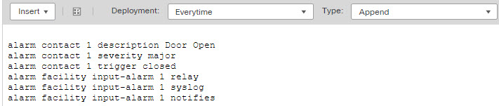
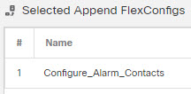
You can connect the alarm input interfaces (or contacts) to external sensors, such as one that detects if a door is open.

Each alarm input interface has a corresponding LED. These LEDs convey the alarm status of each alarm input. You can configure the trigger and severity for each alarm input. In addition to the LED, you can configure the contact to trigger the output relay (to activate an external alarm), to send syslog messages, and to send SNMP traps.

The following table explains the statuses of the LEDs in response to alarm conditions for the alarm inputs. It also explains the behavior for the output relay, syslog messages, and SNMP traps, if you enable these responses to the alarm input.

Alarm Status

LED

Output Relay

Syslog

SNMP Trap

Alarm not configured

Off

No alarms triggered

Solid green

Alarm activated

Minor alarm—solid red

Major alarm—flashing red

Relay energized

Syslog generated

SNMP trap sent

Alarm end

Solid green

Relay de-energized

Syslog generated

Alarm Output Interface

You can connect an external alarm, such as a buzzer or light, to the alarm output interface.

The alarm output interface functions as a relay and also has a corresponding LED, which conveys the alarm status of an external sensor connected to the input interface, and internal sensors such as the dual power supply and temperature sensors. You configure which alarms should activate the output relay, if any.

The following table explains the statuses of the LEDs and output relay in response to alarm conditions. It also explains the behavior for syslog messages, and SNMP traps, if you enable these responses to the alarm.

Alarm Status

LED

Output Relay

Syslog

SNMP Trap

Alarm not configured

Off

No alarms triggered

Solid green

Alarm activated

Solid red

Relay energized

Syslog generated

SNMP trap sent

Alarm end

Solid green

Relay de-energized

Syslog generated

Syslog Alarms

By default, the system sends syslog messages when any alarm is triggered. You can disable syslog messaging if you do not want the messages.

For syslog alarms to work, you must also enable diagnostic logging. Choose Device > Platform Settings, add or edit a Threat Defense platform settings policy that is assigned to the device, and configure destinations and settings on the Syslog page. For example, you can configure a syslog server, console logging, or internal buffer logging.

Without enabling a destination for diagnostic logging, the alarm system has nowhere to send syslog messages.

SNMP Alarms

You can optionally configure the alarms to send SNMP traps to your SNMP server. For SNMP trap alarms to work, you must also configure SNMP settings.

Choose Device > Platform Settings, add or edit a Threat Defense platform settings policy that is assigned to the device, and enable SNMP and configure settings on the SNMP page.

Defaults for Alarms

The following table specifies the defaults for alarm input interfaces (contacts), redundant power supply, and temperature.

Alarm

Trigger

Severity

SNMP Trap

Output Relay

Syslog Message

Alarm Contact 1

Enabled

Closed State

Minor

Disabled

Disabled

Enabled

Alarm Contact 2

Enabled

Closed State

Minor

Disabled

Disabled

Enabled

Redundant Power Supply (when enabled)

Enabled

Disabled

Disabled

Enabled

Temperature

Enabled for the primary temperature alarm (default values of 92°C and -40°C for the high and low thresholds respectively)

Disabled for the secondary alarm.

Enabled for primary temperature alarm

Enabled for primary temperature alarm

Enabled for primary temperature alarm

Requirements and Prerequisites for Alarms

Model Support

Threat Defense on the ISA 3000.

Supported Domains

Any

User Roles

Admin

Configure the Alarms for the ISA 3000

You use FlexConfig to configure alarms for the ISA 3000. The following topics explain how to configure the different types of alarms.

Configure Alarm Input Contacts

If you connect the alarm input contacts (interfaces) to external sensors, you can configure the contacts to issue alarms based on the input from the sensor. In fact, the contacts are enabled by default to send syslog messages if the contact is closed, that is, if the electrical current stops flowing through the contact. You need to configure the contact only if the defaults do not meet your requirements.

The alarm contacts are numbered 1 and 2, so you need to understand how you have wired the physical pins to configure the correct settings. You configure the contacts separately.

Procedure


Step 1

Create the FlexConfig object to configure the alarm input contacts.

  1. Choose Objects > Object Management.

  2. Choose FlexConfig > FlexConfig Object from the table of contents.

  3. Click Add FlexConfig Object, configure the following properties, and click Save.

    • Name—The object name. For example, Configure_Alarm_Contacts.

    • Deployment—Select Everytime. You want this configuration to be sent in every deployment to ensure it remains configured.

    • Type—Keep the default, Append. The commands are sent to the device after the commands for directly-supported features.

    • Object body—In the object body, type the commands needed to configure the alarm contacts. The following steps explain the commands.

  4. Configure a description for the alarm contact.

    alarm contact {1 | 2} description string

    For example, to set the description of contact 1 to "Door Open," enter the following:

    
    alarm contact 1 description Door Open 
    
  5. Configure the severity for the alarm contact.

    alarm contact {1 | 2 | any} severity {major | minor | none}

    Instead of configuring one contact, you can specify any to change the severity for all contacts. The severity controls the behavior of the LED associated with the contact.

    • major —The LED blinks red.

    • minor—The LED is solid red. This is the default.

    • none—The LED is off.

    For example, to set the severity of contact 1 to Major, enter the following:

    
    alarm contact 1 severity major 
    
  6. Configure the trigger for the alarm contact.

    alarm contact {1 | 2 | any} trigger {open | closed}

    Instead of configuring one contact, you can specify any to change the trigger for all contacts. The trigger determines the electrical condition that signals an alert.

    • open —The normal condition for the contact is closed, that is, the electrical current is running through the contact. An alert is triggered if the contact becomes open, that is, the electrical current stops flowing.

    • closed —The normal condition for the contact is open, that is, the electrical current does not run through the contact. An alert is triggered if the contact becomes closed, that is, the electrical current starts running through the contact. This is the default.

    For example, you connect a door sensor to alarm input contact 1, and its normal state has no electrical current flowing through the alarm contact (it is open). If the door is opened, the contact is closed and electrical current flows through the alarm contact. You would set the alarm trigger to closed so that the alarm goes off when the electrical current starts flowing.

    
    alarm contact 1 trigger closed 
    
  7. Configure the actions to take when the alarm contact is triggered.

    alarm facility input-alarm {1 | 2} {relay | syslog | notifies}

    You can configure more than one action. For example, you can configure the device to activate the external alarm, send syslog messages, and also send SNMP traps.

    • relay—Energize the alarm output relay, which activates the external alarm that you attached to it, such as a buzzer or a flashing light. The output LED also goes red.

    • syslog—Send a syslog message. This option is enabled by default.

    • notifies—Send an SNMP trap.

    For example, to enable all actions for the alarm input contact 1, enter the following:

    
    alarm facility input-alarm 1 relay 
    alarm facility input-alarm 1 syslog
    alarm facility input-alarm 1 notifies
    
  8. Verify that the object body contains the commands you want.

    For example, if your template includes all of the command examples shown in this procedure, the object body would have the following commands:

    
    alarm contact 1 description Door Open
    alarm contact 1 severity major 
    alarm contact 1 trigger closed 
    alarm facility input-alarm 1 relay 
    alarm facility input-alarm 1 syslog
    alarm facility input-alarm 1 notifies
    

    The object body should look similar to the following:


    FlexConfig object for configuring alarm contacts on ISA 3000 devices.

  9. Click Save.

Step 2

Create the FlexConfig policy and assign it to the devices.

  1. Choose Devices > FlexConfig.

  2. Either click New Policy, or if an existing FlexConfig policy should be assigned to (or is already assigned to) the target devices, simply edit that policy.

    When creating a new policy, assign the target devices to the policy in the dialog box where you name the policy.

  3. Select the alarm contact FlexConfig object in the User Defined folder in the table of contents and click > to add it to the policy.

    The object should be added to the Selected Appended FlexConfigs list.


    FlexConfig policy, configure alarms object in the selected objects list.

  4. Click Save.

  5. If you have not yet assigned all the targeted devices to the policy, click the Policy Assignments link below Save and make the assignments now.

  6. Click Preview Config, and in the Preview dialog box, select one of the assigned devices.

    The system generates a preview of the configuration CLI that will be sent to the device. Verify that the commands generated from the FlexConfig object look correct. These will be shown at the end of the preview. Note that you will also see commands generated from other changes you have made to managed features. For the alarm contact commands, you should see something similar to the following:

    
    ###Flex-config Appended CLI ###
    alarm contact 1 description Door Open
    alarm contact 1 severity major 
    alarm contact 1 trigger closed 
    alarm facility input-alarm 1 relay 
    alarm facility input-alarm 1 syslog
    alarm facility input-alarm 1 notifies
    

Step 3

Deploy your changes.

Because you assigned a FlexConfig policy to the devices, you will always get a deployment warning, which is meant to caution you about the use of FlexConfig. Click Proceed to continue with the deployment.

After the deployment completes, you can check the deployment history and view the transcript for the deployment. This is especially valuable if the deployment fails. See Verify the Deployed Configuration.


Configure Power Supply Alarms

The ISA 3000 has two power supplies. By default, the system operates in single-power mode. However, you can configure the system to operate in dual mode, where the second power supply automatically provides power if the primary power supply fails. When you enable dual-mode, the power supply alarm is automatically enabled to send syslog alerts, but you can disable the alert altogether, or also enable SNMP traps or the alarm hardware relay.

The following procedure explains how to enable dual mode, and how to configure the power supply alarms.

Procedure


Step 1

Create the FlexConfig object to configure the power supply alarm.

  1. Choose Objects > Object Management.

  2. Choose FlexConfig > FlexConfig Object from the table of contents.

  3. Click Add FlexConfig Object, configure the following properties, and click Save.

    • Name—The object name. For example, Power_Supply_Alarms.

    • Deployment—Select Everytime. You want this configuration to be sent in every deployment to ensure it remains configured.

    • Type—Keep the default, Append. The commands are sent to the device after the commands for directly-supported features.

    • Object body—In the object body, type the commands needed to configure the power supply alarms. The following steps explain the commands.

  4. Enable dual power supply mode.

    power-supply dual

    For example:

    
    power-supply dual 
    
  5. Configure the actions to take when the power supply alarm is triggered.

    alarm facility power-supply rps {relay | syslog | notifies | disable}

    You can configure more than one action. For example, you can configure the device to activate the external alarm, send syslog messages, and also send SNMP traps.

    • relay—Energize the alarm output relay, which activates the external alarm that you attached to it, such as a buzzer or a flashing light. The output LED also goes red.

    • syslog—Send a syslog message. This option is enabled by default.

    • notifies—Send an SNMP trap.

    • disable—Disable the power supply alarm. Any other actions configured for the power supply alarm are inoperable.

    For example, to enable all actions for the power supply alarm, enter the following:

    
    alarm facility power-supply rps relay 
    alarm facility power-supply rps syslog
    alarm facility power-supply rps notifies
    
  6. Verify that the object body contains the commands you want.

    For example, if your template includes all of the command examples shown in this procedure, the object body would have the following commands:

    
    power-supply dual
    alarm facility power-supply rps relay 
    alarm facility power-supply rps syslog
    alarm facility power-supply rps notifies
    

    The object body should look similar to the following:


    FlexConfig object for configuring power supply alarms on ISA 3000 devices.

  7. Click Save.

Step 2

Create the FlexConfig policy and assign it to the devices.

  1. Choose Devices > FlexConfig.

  2. Either click New Policy, or if an existing FlexConfig policy should be assigned to (or is already assigned to) the target devices, simply edit that policy.

    When creating a new policy, assign the target devices to the policy in the dialog box where you name the policy.

  3. Select the power supply alarm FlexConfig object in the User Defined folder in the table of contents and click > to add it to the policy.

    The object should be added to the Selected Appended FlexConfigs list.


    FlexConfig policy, power supply alarms object in the selected objects list.

  4. Click Save.

  5. If you have not yet assigned all the targeted devices to the policy, click the Policy Assignments link below Save and make the assignments now.

  6. Click Preview Config, and in the Preview dialog box, select one of the assigned devices.

    The system generates a preview of the configuration CLI that will be sent to the device. Verify that the commands generated from the FlexConfig object look correct. These will be shown at the end of the preview. Note that you will also see commands generated from other changes you have made to managed features. For the power supply alarm commands, you should see something similar to the following:

    
    ###Flex-config Appended CLI ###
    power-supply dual
    alarm facility power-supply rps relay 
    alarm facility power-supply rps syslog
    alarm facility power-supply rps notifies
    

Step 3

Deploy your changes.

Because you assigned a FlexConfig policy to the devices, you will always get a deployment warning, which is meant to caution you about the use of FlexConfig. Click Proceed to continue with the deployment.

After the deployment completes, you can check the deployment history and view the transcript for the deployment. This is especially valuable if the deployment fails. See Verify the Deployed Configuration.


Configure Temperature Alarms

You can configure alarms based on the temperature of the CPU card in the device.

You can set a primary and secondary temperature range. If the temperature drops below the low threshold, or exceeds the high threshold, the alarm is triggered.

The primary temperature alarm is enabled by default for all alarm actions: output relay, syslog, and SNMP. The default settings for the primary temperature range is -40°C to 92°C.

The secondary temperature alarm is disabled by default. You can set the secondary temperature within the range -35°C to 85°C.

Because the secondary temperature range is more restrictive than the primary range, if you set either the secondary low or high temperature, that setting disables the corresponding primary setting, even if you configure non-default values for the primary setting. You cannot enable two separate high and two separate low temperature alarms.

Thus, in practice, you should configure the primary only, or the secondary only, setting for high and low.

Procedure


Step 1

Create the FlexConfig object to configure the temperature alarms.

  1. Choose Objects > Object Management.

  2. Choose FlexConfig > FlexConfig Object from the table of contents.

  3. Click Add FlexConfig Object, configure the following properties, and click Save.

    • Name—The object name. For example, Configure_Temperature_Alarms.

    • Deployment—Select Everytime. You want this configuration to be sent in every deployment to ensure it remains configured.

    • Type—Keep the default, Append. The commands are sent to the device after the commands for directly-supported features.

    • Object body—In the object body, type the commands needed to configure the temperature alarms. The following steps explain the commands.

  4. Configure the acceptable temperature range.

    alarm facility temperature {primary | secondary} {low | high} temperature

    The temperature is in Celsius. The allowed range for the primary alarm is -40 to 92, which is also the default range. The allowed range for the secondary alarm is -35 to 85. The low value must be lower than the high value.

    For example, to set a more restrictive temperature range of -20 to 80, which falls within the allowed range for the secondary alarm, configure the secondary alarm as follows:

    
    alarm facility temperature secondary low -20
    alarm facility temperature secondary high 80 
    
  5. Configure the actions to take when the temperature alarm is triggered.

    alarm facility temperature {primary | secondary} {relay | syslog | notifies}

    You can configure more than one action. For example, you can configure the device to activate the external alarm, send syslog messages, and also send SNMP traps.

    • relay—Energize the alarm output relay, which activates the external alarm that you attached to it, such as a buzzer or a flashing light. The output LED also goes red.

    • syslog—Send a syslog message.

    • notifies—Send an SNMP trap.

    For example, to enable all actions for the secondary temperature alarm, enter the following:

    
    alarm facility temperature secondary relay 
    alarm facility temperature secondary syslog
    alarm facility temperature secondary notifies
    
  6. Verify that the object body contains the commands you want.

    For example, if your template includes all of the command examples shown in this procedure, the object body would have the following commands:

    
    alarm facility temperature secondary low -20
    alarm facility temperature secondary high 80 
    alarm facility temperature secondary relay 
    alarm facility temperature secondary syslog
    alarm facility temperature secondary notifies
    

    The object body should look similar to the following:


    FlexConfig object for configuring temperature alarms on ISA 3000 devices.

  7. Click Save.

Step 2

Create the FlexConfig policy and assign it to the devices.

  1. Choose Devices > FlexConfig.

  2. Either click New Policy, or if an existing FlexConfig policy should be assigned to (or is already assigned to) the target devices, simply edit that policy.

    When creating a new policy, assign the target devices to the policy in the dialog box where you name the policy.

  3. Select the temperature alarms FlexConfig object in the User Defined folder in the table of contents and click > to add it to the policy.

    The object should be added to the Selected Appended FlexConfigs list.


    FlexConfig policy, configure temperature alarms object in the selected object list.

  4. Click Save.

  5. If you have not yet assigned all the targeted devices to the policy, click the Policy Assignments link below Save and make the assignments now.

  6. Click Preview Config, and in the Preview dialog box, select one of the assigned devices.

    The system generates a preview of the configuration CLI that will be sent to the device. Verify that the commands generated from the FlexConfig object look correct. These will be shown at the end of the preview. Note that you will also see commands generated from other changes you have made to managed features. For the temperature alarms commands, you should see something similar to the following:

    
    ###Flex-config Appended CLI ###
    alarm facility temperature secondary low -20
    alarm facility temperature secondary high 80 
    alarm facility temperature secondary relay 
    alarm facility temperature secondary syslog
    alarm facility temperature secondary notifies
    

Step 3

Deploy your changes.

Because you assigned a FlexConfig policy to the devices, you will always get a deployment warning, which is meant to caution you about the use of FlexConfig. Click Proceed to continue with the deployment.

After the deployment completes, you can check the deployment history and view the transcript for the deployment. This is especially valuable if the deployment fails. See Verify the Deployed Configuration.


Monitoring Alarms

The following topics explain how to monitor and manage alarms.

Monitoring Alarm Status

You can use the following commands in the CLI to monitor alarms.

  • show alarm settings

    Shows the current configuration for each possible alarm.

  • show environment alarm-contact

    Shows information about the physical status of the input alarm contacts.

  • show facility-alarm relay

    Shows information about the alarms that have triggered the output relay.

  • show facility-alarm status [info | major | minor]

    Shows information on all alarms that have been triggered. You can limit the view by filtering on major or minor status. The info keyword provides the same output as using no keyword.

Monitoring Syslog Messages for Alarms

Depending on the type of alarms you configure, you might see the following syslog messages.

Dual Power Supply Alarms
  • %FTD-1-735005: Power Supply Unit Redundancy OK

  • %FTD-1-735006: Power Supply Unit Redundancy Lost

Temperature Alarms

In these alarms, Celsius is replaced by the temperature detected on the device, in Celsius.

  • %FTD-6-806001: Primary alarm CPU temperature is High Celsius

  • %FTD-6-806002: Primary alarm for CPU high temperature is cleared

  • %FTD-6-806003: Primary alarm CPU temperature is Low Celsius

  • %FTD-6-806004: Primary alarm for CPU Low temperature is cleared

  • %FTD-6-806005: Secondary alarm CPU temperature is High Celsius

  • %FTD-6-806006: Secondary alarm for CPU high temperature is cleared

  • %FTD-6-806007: Secondary alarm CPU temperature is Low Celsius

  • %FTD-6-806008: Secondary alarm for CPU Low temperature is cleared

Alarm Input Contact Alarms

In these alarms, description is the description for the contact that you configured.

  • %FTD-6-806009: Alarm asserted for ALARM_IN_1 alarm_1_description

  • %FTD-6-806010: Alarm cleared for ALARM_IN_1 alarm_1_description

  • %FTD-6-806011: Alarm asserted for ALARM_IN_2 alarm_2_description

  • %FTD-6-806012: Alarm cleared for ALARM_IN_2 alarm_2_description

Turning Off the External Alarm

If you are using an external alarm that is attached to the alarm output, and the alarm is triggered, you can turn off the external alarm from the device CLI using the clear facility-alarm output command. This command de-energizes the output pin and also turns off the output LED.

History for Alarms

Feature

Minimum Management Center

Minimum Threat Defense

Description

Alarms for the Cisco ISA 3000 series.

6.7

Any

Configuring alarms for the Cisco ISA 3000 series was validated using FlexConfig. You should be able to configure the alarms in older releases that support FlexConfig, except for the dual power supply alarms.

Supported platforms: Secure Firewall Threat Defense on the ISA 3000.