5G-UPF Overview

This chapter covers the following topics:

Feature Summary and Revision History

Summary Data

Table 1. Summary Data
Applicable Product(s) or Functional Area 5G-UPF
Applicable Platform(s)

VPC-SI

SMI

Feature Default Setting Disabled – License Required
Related Changes in this Release Not Applicable
Related Documentation Not Applicable

Revision History

Table 2. Revision History
Revision Details Release

Added support for UPF cloud-native deployment.

2023.01.0

First introduced.

2020.02.0

Product Description

The User Plane Function (UPF) is one of the network functions (NFs) of the 5G core network (5GC). The UPF is responsible for packet routing and forwarding, packet inspection, QoS handling, and external PDU session for interconnecting Data Network (DN), in the 5G architecture.

UPF is a distinct Virtual Network Function (VNF) that offers a high-performance forwarding engine for the user traffic. Using Vector Packet Processing (VPP) technology, the UPF achieves ultra-fast packet forwarding while retaining compatibility with all the user plane functionality. For instance, Shallow Packet Inspection(SPI)/Deep Packet Inspection (DPI), traffic optimization, and inline services (NAT, Firewall, DNS snooping, and so on). UPF is currently designed to offer Integrated Deep Packet Based Inspection (DPI) Services.

A single instance of UPF provides some or all the following functionalities:

  • Anchor point for Intra-RAT and Inter-RAT mobility (when applicable).

  • External PDU session point of interconnect to Data Network.

  • Packet routing and forwarding.

  • Packet inspection. For example, Application detection that is based on the service data flow template and the optional PFDs received from the SMF in addition.

  • User Plane part of policy rule enforcement. For example, Gating, Redirection, Traffic steering.

  • Lawful intercept (UP collection).

  • Traffic usage reporting.

  • QoS handling for User Plane. For example, Uplink (UL) and Downlink (DL) rate enforcement, Reflective QoS marking in DL, and so on.

  • Uplink Traffic verification (SDF to QoS Flow mapping).

  • Transport level packet marking in the Uplink and Downlink.

  • Downlink packet buffering and Downlink Data Notification triggering.

  • Sending and forwarding of one or more "End Marker" to the source NG-RAN node.

The UPF also provides support for an enterprise mobile virtual network operator (MVNO) model, which enables a mobile network operator (MNO) to perform secondary authentication for the leased MVNO subscribers.

Use Cases and Features

Configuration and Deployment Requirement for UPF

With 5G deployment, interoperability is required between Cisco UPF with non-Cisco SMF, and Cisco SMF with non-Cisco UPF. Also, decoupling of configuration-related messaging between SMF and UPF has the following benefits:

  • Alignment with 3GPP standards for configuration bifurcation between User Plane and Control Plane.

  • Reduced complexity for configuration management on SMF.

  • Simplicity and efficiency for the configuration and change management for User Plane related configuration, as it does not require SMF to manage and distribute the configuration.

  • Can be enhanced to achieve interworking between non-Cisco SMF and UPFs.

The Cisco UPF supports 3GPP-specified attributes on the N4 interface. In the current architecture, only UPF associates with the SMF.

The following features are related to this use case:

Anchor Point for Intra-RAT and Inter-RAT Mobility

The UPF is the anchor point between the mobile infrastructure and the Data Network (DN). That is, the encapsulation and decapsulation of GPRS Tunneling Protocol for the User Plane (GTP-U). Intra-RAT mobility like Xn handover and inter-RAT mobility like 4G to 5G and 5G to 4G handover are supported for this use case.

The GTP-U Support feature is related to this use case.

External PDU Session Point of Interconnect to Data Network

The UPF acts as an external PDU session point of interconnect to Data Network and supports N3, N4, and N6 interfaces. The PDU layer corresponds to the PDU that is transported between the UE and the PDN during a PDU session. The PDU session can be of type IPv4 or IPv6 for transporting IP packets. The GPRS tunneling protocol for the user plane (GTP-U) supports multiplexing of the traffic from different PDU sessions by tunneling user data over the N3 interface (between a 5G access node and the UPF) in the core network. The GTP encapsulates all end-user PDUs and provides encapsulation per-PDU session. This layer also transports the marking associated with the QoS flow. The 5G encapsulation layer supports multiplexing the traffic from different PDU sessions over the N9 interface (an interface between different UPFs). It provides encapsulation per PDU session and carries the marking associated with the QoS flows.

The following features are related to this use case:

Packet Inspection

The Cisco UPF performs L3/L4 and L7 inspection for the user traffic that is received. L3/L4 inspection involves IP-address/port matching and Deep Packet Inspection involves matching of L7 header fields.

The Deep Packet Inspection and Inline Services feature is related to this use case.

User Plane Part of Policy Rule Enforcement

Cisco UPF provides different enforcement mechanisms based on policy received from the SMF. The UPF is the boundary between the Access and IP domains and is the ideal location to implement policy-based enforcement. The pcc-rules provided by the PCF and the pre-defined rules on the SMF are uploaded over the N4 interface and installed on the UPF on a per-DNN basis. This allows for dynamic policy changes that enable differentiated charging and QoS enforcement.

Lawful Intercept

Lawful Interception (LI) enables a LEA to perform electronic surveillance on an individual (a target) as authorized by a judicial or administrative order. To facilitate the lawful intercept process, certain legislation and regulations require service providers and Internet service providers to implement their networks to explicitly support authorized electronic surveillance. Actions taken by the service providers include: provisioning the target identity in the network to enable isolation of target communications (separating it from other users' communications), duplicating the communications for the purpose of sending the copy to the LEA, and delivering the Interception Product to the LEA.

For information about the support of Lawful Intercept by UPF, contact your Cisco Account representative.

Traffic Usage Reporting (Charging)

The usage measurement and reporting function in UPF is controlled by the SMF. The SMF controls these functions by:

  • Creating the necessary PDRs to represent the service data flow, application, bearer or session (if they are not existing already).

  • Creating the URRs for each Charging Key and combination of Charging Key and Service ID. Also, creating URRs for a combination of Charging Key, Sponsor ID, and Application Service Provider ID.

    Please note that, for static rules, the UPF creates the URR ID. The URR ID is created based on the online/offline and Content ID+Service ID combination that is configured on UPF.

  • Associating the URRs to the relevant PDRs defined for the PFCP session, for usage reporting at SDF, Session or Application level.

  • For online charging, the SMF provisions Volume and Time quota, if it receives it from the Online Charging Server (OCS).

The Charging Support feature is related to this use case.

QoS Handling for User Plane

The 5G QoS model allow classification and differentiation of specific services, based on subscription-related and invocation-related priority mechanisms. These mechanisms provide abilities such as invoking, modifying, maintaining, and releasing QoS Flows with priority, and delivering QoS Flow packets according to the QoS characteristics under network congestion conditions.

The Dynamic and Static PCC Rules feature is related to this use case.

Downlink Packet Buffering and Data Notification Triggering

A Buffering Action Rule (BAR) provides instructions to control the buffering behavior of the UPF. The BAR controls the buffering behavior for all Forwarding Action Rules (FARs) of the Packet Forwarding Control Protocol (PFCP) session. This control is applicable when the PFCP session is set with an Apply Action parameter, which requests packets to be buffered and associated with the respective BAR.

The Idle Mode Buffering and Paging feature is related to this use case.

Forwarding End Markers to the Source NG-RAN Node

At the time of the handover procedure, the PDU session for the UE – which comprises of UPF node – acts as a PDU session anchor and an intermediate UPF terminating N3 reference point. The SMF sends an N4 Session Modification Request message with the new AN Tunnel Info of NG-RAN to specify the UPF to switch to the N3 paths. In addition, the SMF also specifies the UPF to send the End Marker packets on the old N3 user plane path. After the UPF receives the indication, the End Markers are constructed and sent to each N3 GTP-U tunnel toward the source NG-RAN, after sending the last PDU on the old path.

The N4 Session Management, Node Level, and Reporting Procedures feature is related to this use case.

MVNO Support

The UPF provides support for an enterprise MVNO model. A mobile network operator can perform secondary authentication for the leased MVNO subscribers and also support any additional features related to the AAA server.

The following features are related to this use case:

Deployment Architecture and Interfaces

Cisco UPF is part of the 5GC network functions portfolio (AMF/SMF/NRF/PCF/NSSF/UPF) with a common Mobile Core Platform architecture.

UPF Architecture

The User Plane Function (UPF) is a fundamental component of a 3GPP 5G core infrastructure system architecture. The UPF represents the data plane evolution of a Control and User Plane Separation (CUPS) strategy, first introduced as an extension to existing Evolved Packet Cores (EPCs) by the 3GPP in Release 14 specifications. The CUPS decoupless Packet Gateway (P-GW) Control and User Plane functions, enabling the data forwarding component (PGW-U) to be decentralized. This allows packet processing and traffic aggregation to be performed closer to the network edge, increasing bandwidth efficiencies while reducing network load. The P-GW handling signaling traffic (PGW-C) remains in the core, northbound of the Mobility Management Entity (MME).

The primary goal of CUPS is to support 5G New Radio (NR) implementations enabling early IoT applications and higher data rates. Committing to a complete implementation of CUPS is a complex proposition as it only provides a subset of advantages to the operator adopting a 5G User Plane Function (5G-UPF), offering network slicing. Deployed as a Virtual Machine (VM), the User Plane Function delivers the packet processing foundation for Service-Based Architectures (SBAs).

The UPF identifies User Plane traffic flow that is based on information that is received from the SMF over the N4 reference point. The N4 interface employs the Packet Forwarding Control Protocol (PFCP), which is defined in the 3GPP technical specification 29.244 for use on Sx/N4 reference points in support of CUPS. The PFCP is similar to OpenFlow but can be limited to only the functionality that is required to support mobile networks. The PFCP sessions, which are established with the UPF, define how packets are identified (Packet Detection Rule / PDR), forwarded (Forwarding Action Rules / FARs), processed (Buffering Action Rules / BARs), marked (QoS Enforcement Rules / QERs) and reported (Usage Reporting Rules / URRs).

UPF Deployment Architecture

The following diagram illustrates the high-level deployment architecture of UPF along with other NFs.

VM Deployment

Virtualized Packet Core—Single Instance (VPC-SI)

VPC-SI consolidates the operations of a physical Cisco ASR 5500 chassis running StarOS into a single Virtual Machine (VM) able to run on commercial off-the-shelf (COTS) servers. VPC-SI can be used as a stand-alone single VM within an enterprise, remote site, or customer data center. Alternatively, VPC-SI can be integrated as part of a larger service provider orchestration solution.

VPC-SI only interacts with supported hypervisors KVM (Kernel-based Virtual Machine) and VMware ESXi. It has little or no knowledge of physical devices.

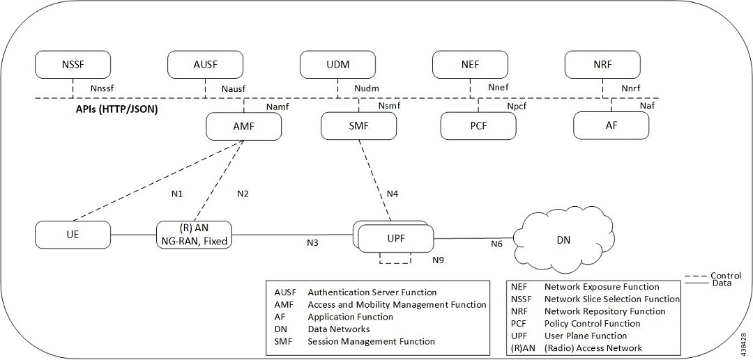
The UPF functions as user plane node in 5G-based VNF deployments. UPF is deployed as a VNFC running a single, stand-alone instance of the StarOS. Multiple UPF VNFCs can be deployed for scalability based on your deployment requirements.

Hypervisor Requirements

VPC-SI has been qualified to run under the following hypervisors:

  • Kernel-based Virtual Machine (KVM) - QEMU emulator 2.0. The VPC-SI StarOS installation build includes a libvirt XML template and ssi_install.sh for VM creation under Ubuntu Server 18.04.


    Note


    When a port on the UPF is shutdown and brought up subsequently, the port interfaces are visible in Ubuntu version 18.04 and NIC driver i40e version 2.12.6. BGP on these interfaces does not recover automatically.

    To fully restore the UPF, you must reload the UPFs. In Ubuntu version 20.04 and NIC driver i40e version 2.17.15, both port interfaces and BGP recover automatically.


  • KVM - Red Hat Enterprise Linux 7.2: The VPC-SI StarOS installation build includes an install script called qvpc-si_install.sh.

  • VMware ESXi 6.7: The VPC-SI StarOS installation build includes OVF (Open Virtualization Format) and OVA (Open Virtual Application) templates for VM creation via the ESXi GUI.

vNIC Options

The supported vNIC options include:

  • VMXNET3—Paravirtual NIC for VMware

  • VIRTIO—Paravirtual NIC for KMV

  • ixgbe—Intel 10-Gigabit NIC virtual function

  • enic—Cisco UCS NIC

  • SR-IOV—Single-root I/O virtualization

The SR-IOV specification provides a mechanism by which a single root function (for example, a single Ethernet port) can appear to be multiple separate physical devices. Intel 82599 10G is an SR-IOV capable device and can be configured (usually by the Hypervisor) to appear in the PCI configuration space as multiple functions (PFs and VFs). The virtual functions (VFs) can be assigned to Nova VMs, causing traffic from the VMs to bypass the Hypervisor and go directly to the fabric interconnect. This feature increases traffic throughput to the VM and reduces CPU load on the UCS Servers.

Capacity, CEPS and Throughput

Sizing a VPC-SI instance requires modeling of the expected call model.

Many service types require more resources than others. Packet size, throughput per session, CEPS (Call Events per Second) rate, IPsec usage (site-to-site, subscriber, LI), contention with other VMs, and the underlying hardware type (CPU speed, number of vCPUs) will further limit the effective number of maximum subscribers. Qualification of a call model on equivalent hardware and hypervisor configuration is required.

Sample VPP Configuration

For 5G-UPF, the FORWARDER_TYPE is "vpp".

The following is a sample output of VPP configuration.

show cloud configuration 
Thursday January 30 12:18:10 UTC 2020
Card 1:
  Config Disk Params:
-------------------------
FORWARDER_TYPE=vpp
VNFM_INTERFACE=MAC:fa:11:3e:22:d8:33
MGMT_INTERFACE=MAC:fa:11:3e:44:af:9e
VNFM_IPV4_ENABLE=true
VNFM_IPV4_DHCP_ENABLE=true
SERVICE1_INTERFACE=MAC:fa:11:3e:11:9d:23
SERVICE2_INTERFACE=MAC:fa:11:3e:99:ec:7b
VPP_CPU_WORKER_CNT=8
VPP_DPDK_TX_QUEUES=9
VPP_DPDK_RX_QUEUES=8
CHASSIS_ID=xxxxxxxxxxxxxxxxxxxxxxxxxxxxxxxxxxxxxxxxxxxxxxxxxxxx

  Local Params:
-------------------------
    No local param file available 

Note


For additional information about VPC-SI build components, boot parameters, configuring VPC-SI boot parameters, VM configuration, vCPU and vRAM options, VPP configuration parameters, and so on, refer the VPC-SI System Administration Guide.


UPF Deployment with VPC-SI

For additional information on VPC-SI, supported operating system and hypervisor packages, platform configurations, software download and installation, and UPF deployment, contact your Cisco Account representative.

For information on Release Package, refer the corresponding Release Notes included with the build.

UPF Deployment with SMI Cluster Manager

The Ultra Cloud Core Subscriber Microservices Infrastructure (SMI) provides a run time environment for deploying and managing Cisco Cloud-Native Network Functions (CNFs), also referred to as applications.

It is built around Open Source projects like Kubernetes (K8s), Docker, Helm, etcd, confd, and gRPC, and provides a common set of services used by deployed cNFs.

The SMI is a layered stack of cloud technologies that enable the rapid deployment of, and seamless life-cycle operations for microservices-based applications.

The SMI stack consists of SMI Cluster Manager that creates the Kubernetes (K8s) cluster and the software repository. The SMI Cluster Manager also provides ongoing Life Cycle Management (LCM) for the cluster including deployment, upgrades, and expansion.

The SMI Cluster Manager leverages the Kernel-based Virtual Machine (KVM)—a virtualization technology—to deploy the User Plane Function (UPF) VMs.

For more information, refer the UCC SMI Operations Guide.

Same UP Pools for SAEGW-C and SMF

The same pool of UPs can be used by SAEGW and SMF. The user plane can act as UP and UPF at the same time. It can serve SAEGW over the Sx interface and SMF over the N4 interface. The same subscriber IP pool on SAEGW and SMF is supported only with different VRFs.

This functionality is qualified for the user plane acting as UP and UPF to simultaneously support CUPS and SAEGW Sx interfaces (Sxa, Sxb, and Sxab) for 2G, 3G, 4G RAT, and SMF N4 interface for 5G call.


Note


The combined UP and UPF call is not qualified in this release.


Supported Interfaces

This section describes the interfaces supported between the UPF and other network functions in 5GC.

  • N3: Interface between the RAN (gNB) and the (initial) UPF; compliant with 3GPP TS 29.281 and 3GPP TS 38.415 (December-2018).

  • N4: Interface between the Session Management Function (SMF) and the UPF; compliant with 3GPP TS 29.244 (December-2018).

  • N6: Interface between the Data Network (DN) and the UPF; compliant with 3GPP TS 29.561 (December-2018).

  • Sx: Interface between the Control-Plane and User-Plane in a split P-GW, S-GW, and TDF architecture in an Evolved Packet Core (EPC); compliant with 3GPP TS 23.214 and 3GPP TS 33.107.

License Information

The UPF requires specific license(s). Contact your Cisco account representative for more information on how to obtain a license.

Standards Compliance

Cisco UPF complies with the following standards:

  • Interface between the Control Plane and the User Plane Nodes: 3GPP TS 29.244 version 15.4.0. (December-2018)

  • General Packet Radio System (GPRS) Tunneling Protocol User Plane (GTPv1-U): 3GPP TS 29.281 version 15.5.0 (December-2018).

  • NG-RAN; PDU Session User Plane protocol: 3GPP TS 38.415 (December-2018)

  • 5G System; Interworking between 5G Network and external Data Networks; Stage 3: 3GPP TS 29.561 (December-2018)