LTE - Wi-Fi Seamless Handover

Feature Summary and Revision History

Summary Data

Applicable Product(s) or Functional Area 5G-UPF
Applicable Platform(s)

VPC-SI

SMI

Feature Default Setting Enabled - Always-on
Related Changes in this Release Not Applicable
Related Documentation Not Applicable

Revision History

Revision Details

Release

First introduced.

2021.02.0

Feature Description

Seamless handovers between LTE and Wi-Fi (S2b), for UEs that need continuity with their ongoing data session, is supported in the 5G UPF architecture.

When handover is initiated from LTE to Wi-Fi, the Delete Bearer Request (DBR) is sent over the LTE tunnel immediately when the Create Session Response (CSR) is sent on the Wi-Fi tunnel. This causes some packet loss because of the IPsec tunnel establishment delay at the ePDG. To address the issue of packet loss, a Delete Bearer Request is sent on LTE tunnel only on expiry of the configured handover timer. If the LTE tunnel is active, uplink and downlink data is exchanged on the LTE tunnel. When handover is complete, uplink and downlink data is exchanged on the Wi-Fi tunnel. This prevents packet loss. During Wi-Fi to LTE handover, if the Modify Bearer Request is received with HI=1, it initiates a tunnel switch from Wi-Fi to LTE as per the specification.

With this feature, the following benefits are seen:

  • Minimum packet loss during LTE to Wi-Fi (S2bGTP) handover and making the handover seamless (that is, MAKE before BREAK).

  • LTE procedures are handled gracefully over the LTE tunnel when both tunnels are established with the P-GW.

  • Wi-Fi procedures are handled gracefully over the Wi-Fi tunnel when both tunnels are established with the P-GW.


Important


  • In an LTE to Wi-Fi or Wi-Fi to LTE handover, a tunnel identifier is allocated for new access traffic type for experiencing seamless handover.


How It Works

EPC to Non-3GPP Untrusted Wi-Fi Handover Call Flow

This section describes the EPC to non-3GPP untrusted Wi-Fi handover call flow.

Figure 1. EPC to Non-3GPP Untrusted Wi-Fi Handover Call Flow
Table 1. EPC to Non-3GPP Untrusted Wi-Fi Handover Call Flow Description
Step Description
1

The UE is attached to the 3GPP access network.

The SMF+PGW-C communicates with UPF, PCF, and CHF for IPv4, IPv6, or dual-stack to establish 4G LTE PDU session. The PCF sends the Policy Control Request trigger, which is the SM policy decision, in response to SM policy control create. The CHF provides session-level or rating-group-level triggers to the SMF in Charging Data Create response.

2 The UE connects to an untrusted non-3GPP access and an ePDG is selected through the ePDG selection process. Then, the UE initiates the handover attach procedure as defined in 3GPP TS 23.402, section 8.6.2.1. After the IKE tunnel is established between the UE and ePDG and after the UE is authenticated over SWm interface with AAA server, the UE initiates IKE authentication (IKE_AUTH). The IKE_AUTH includes configuration parameters of the earlier assigned IPv4 or IPv6 addresses in the EPC and P-CSCF and the DNS options.
3

The ePDG sends a Create Session Request to the P-GW. This request includes the following details:

  • IMSI

  • APN

  • Handover indication

  • RAT type

  • ePDG TEID of the Control Plane

  • ePDG address for the User Plane

  • ePDG TEID of the User Plane

  • EPS bearer identity

  • User location

The RAT type indicates the non-3GPP access technology type. If the UE supports the IP address preservation and is included in the port analyzer adapter (PAA), then the ePDG configures the handover indication in the Create Session Request to allow the PDN gateway to reallocate the same IP address or the prefix assigned to the UE. This IP address or prefix is assigned while UE is connected to the 3GPP IP access and initiates the policy modification procedure with PCF.

4a

The SMF performs UDM registration by updating the PGW-C FQDN with UDM.

The UDM registration does not occur during the session establishment with EPC.

4b The SMF detects the charging triggers with the information available in Step 3 against the charging triggers that are received during EPC session establishment.
4c The SMF detects the PCF triggers with the information available in Step 3 against the Request Policy Control triggers that are received in the communication with PCF during EPC session establishment.
5 Based on the detected armed Policy Control Triggers that are received in Step 4b, the SMF sends the SM Policy Control Update request with the detected access parameters in Step 3 to the PCF.
6 The PCF includes new or updated PCC rules and sends the SM Policy Control Update response. The Update response includes information on the SM policy decision.
7 Based on the information received in Step 6 and existing policy data of EPC session, SMF prepares the information for the new or updated PCC rules.
8 If new PCC rules are received in Step 6 with new Rating Group that requires quota information, SMF sends the Charging Update request to CHF. SMF also includes new access parameters for the PDU session information.
9 CHF sends the Charging Update Response with multi-unit information that contains quota information for the requested rating-group in Step 8 to SMF. CHF may also send the new quota information for the existing rating-group of EPC session.
10 SMF processes the information that is received as Charging Update response from CHF.
11 SMF sends the N4 session modification request to UPF for Wi-Fi tunnel. This request includes details on creation of uplink PDR, creation of QER, creation of URR for received new rating-group quota information, and update on URR for modified quota information.
12 UPF sends the UL tunnel information that is in created PDR as the N4 session modification response to SMF.
13 SMF sends the GTPv2 Create Session response to S-GW. This response details on request accepted or request accepted partially, P-GW S2b F-TEID, PAA, APN-AMBR, bearer context creation, charging gateway address, and APCO.
14 SMF sends the GTPv2 Create Bearer request to S-GW. This request includes information on bearer context list, which contains DL tunnel information to end-user, to be created.
15 S-GW sends the GTPv2 Create Bearer response to SMF. The response includes details on request accepted or request accepted partially and bearer contexts.
16 SMF processes the Create Bearer response and derives the DL tunnel Information for the established bearer and the the failed EBI list, if any. SMF sends the N4 session modification request to UPF for Wi-Fi tunnel. This request is to create the DL PDR and DL FAR with DL tunnel information for each bearer, RAT modification information, and to delete resources for the 4G tunnel. SMF also deletes the N4 resources of Wi-Fi tunnel for the received failed EBI list or the failed QFI list.
17 UPF sends the usage report as N4 Session Modification response to SMF.
18 SMF+PGW-C sends the GTPv2 DB request to S-GW. This request includes EBI or list of EBIs.
19 S-GW sends the GTPv2 DB response to SMF+PGW-C.
20 SMF sends the Charging Update request to CHF. This request includes the PDU session information with the new access params and multi-usage report containing details on the access params and usage report that is received in Step 8
21 CHF sends the multi-unit information as Charging Update response to SMF. The multi-unit information may include new quota information for the existing rating-groups.
22

SMF sends the SM Policy Control Update request to UPF. This request includes the new access params and rule report for failed QFI list that is received from AMF as part of Create Bearer response.

PCF sends the SM policy decision as SM Policy Control Update response.

SMF processes the SM policy decision and handles it as PCF Initiation Modify procedure as defined in 3GPP 23.502, section 4.3.3.2.

Non-3GPP Untrusted Wi-Fi to EPC Handover Call Flow

This section describes the non-3GPP untrusted Wi-Fi to EPC handover call flow.

Figure 2. Non-3GPP Untrusted Wi-Fi to EPC Handover Call Flow
Table 2. Non-3GPP Untrusted Wi-Fi to EPC Handover Call Flow Description
Step Description
1 One or more PDU sessions are established between UE and ePDG through untrusted non-3GPP access. With the 5G NAS capability of UE, ePDG selects a combined PGW+SMF. UE sends the PDU session ID to the PGW+SMF.
2

UE discovers the E-UTRAN access and hands over the sessions from the currently used non-3GPP access system to E-UTRAN. For details on UE discovery of the 3GPP access system, see 3GPP TS 23.401, section 4.8.

UE sends an Attach request to MME for the Handover Attach request type. E-UTRAN routes the messages received from UE to MME as defined in 3GPP TS 23.401. UE includes the one of the APNs which are corresponding to the PDN connections in the source non-3GPP access. The APN is provided as defined in 3GPP TS 23.401.

3

MME and HSS perform authentication, which is followed by location update procedure and subscriber data retrieval to receive the APN information.

The MME selects an APN, an SGW and PDN gateway as defined in 3GPP TS 23.401. MME sends a Create Session Request message to SGW. This request includes information on IMSI, MME context ID, PDN-GW address, handover indication for the “handover” request type, and APN.

4

SGW sends a Create Session Request, which is handover indication, message to PDN-GW in the HPLMN as described in 3GPP TS 23.401. As the MME includes the handover indication information in the Create Session Request message, the SGW sends the GTPv2 Create Session Request message to PDN GW. This message includes details on IMSI, APN, handover indication, RAT type, S5-C TEID, S5-U TEID of the user plane, EBI, and user location information. The RAT type indicates the 3GPP IP access E-UTRAN technology type. If the UE supports IP address preservation and is included in PAA, the SGW configures the handover indication in the Creation Session Request. With this configuration, the PDN GW re-allocates the same IP address or prefix that was assigned to the UE while it was connected to the 3GPP IP access. With this configuration, SGW initiates the Policy Modification Procedure to the PCF.

As the handover indication is includes, the PDN GW does not switch the tunnel from non-3GPP IP access to 3GPP access system at this point.

SMF does not perform the UDM Registration as the registration happens during the Wi-Fi session establishment.
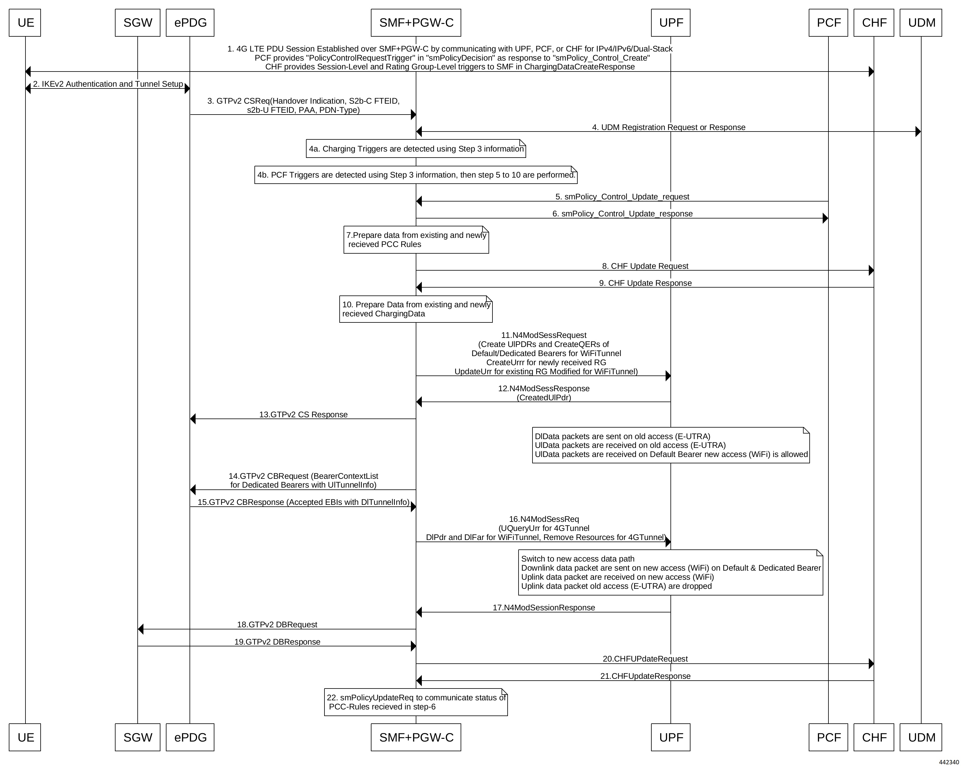
4a SMF detects the charging triggers with the information available in Step 3 against the charging triggers that are received during EPC session establishment.
4b SMF detects the PCF triggers with the information available in Step 3 against the Request Policy Control triggers that are received in the communication with PCF during EPC session establishment.
5 Based on the detected armed Policy Control Triggers that are received in Step 4b, SMF sends the SM Policy Control Update request with the detected access parameters in Step 3 to PCF.
6 PCF sends the SM Policy Control Update response, which is the SM policy decision, by including new or updated PCC rules.
7 Based on the information received in Step 6 and existing policy data of EPC session, SMF prepares the information for the new or updated PCC rules.
8 If SMF receives new PCC rules in Step 6, the SMF sends the Charging Update request, with the new rating-group having quota information, to CHF. This request includes the PDU session information with the new access params.
9 CHF sends the multi-unit information as Charging Update response to SMF. The multi-unit information includes new quota information for the rating-group and the existing rating-group of EPC session, if any.
10 SMF prepares the charging data of the received Charging Update Response that CHF sent.
11 SMF sends the N4 Session Modification Request to UPF. This request includes the details on creation of UL and DL PDR, creation of QER, creation of URR for received new rating-group quota information, updated URR for modified quota information, and creation of FAR.
12 UPF sends the UL tunnel information in the created PDR as N4 Session Modification response to SMF.
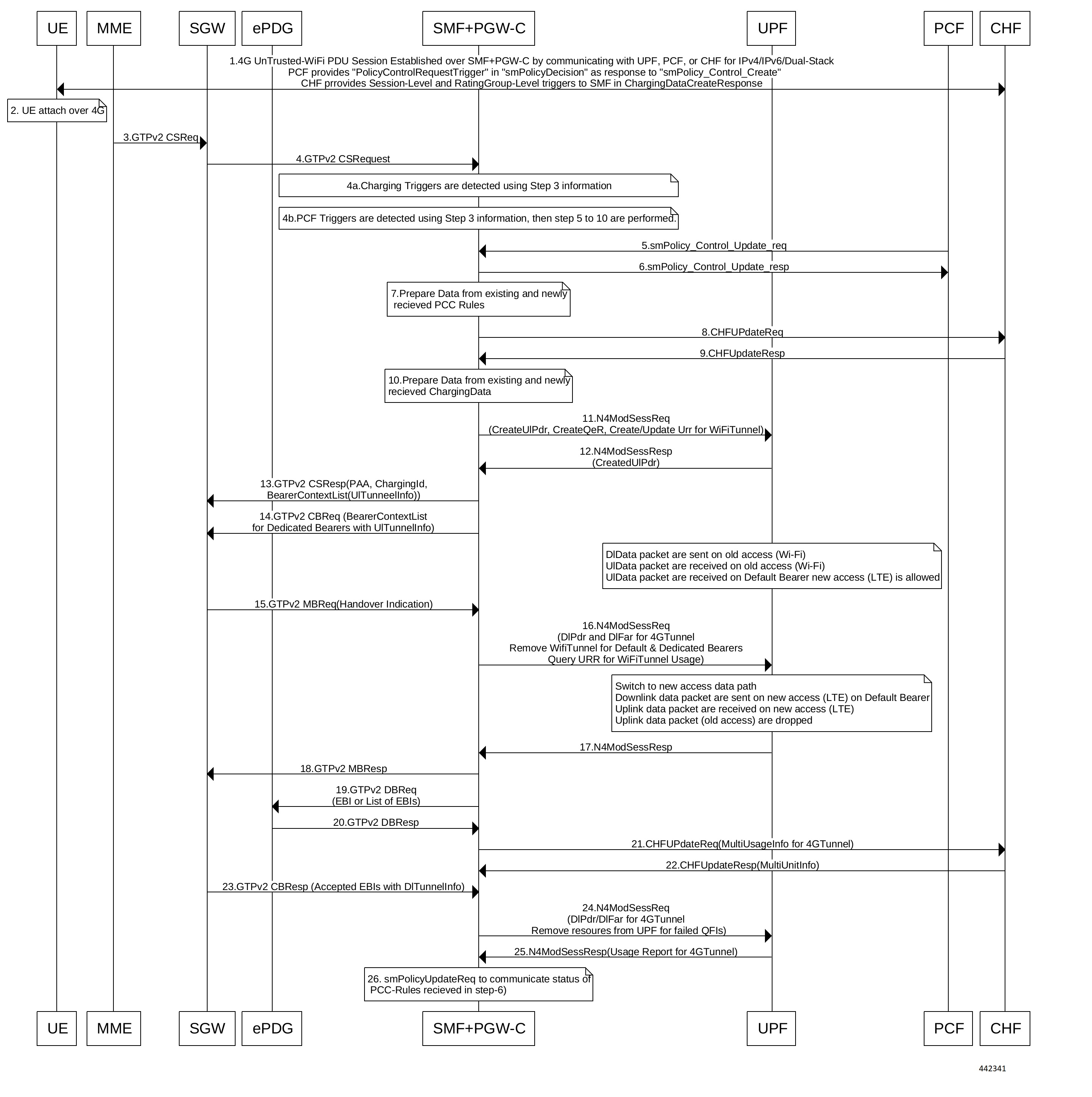
13 SMF sends the GTPv2 Create Session response to S-GW. This response details on request accepted or request accepted partially, P-GW S2b F-TEID, PAA, APN-AMBR, bearer context creation, charging gateway address, and APCO.
14 SGW sends the Modification Bearer request with handover indication to PGW for data path switching from Wi-Fi tunnel to 4G tunnel.
15 PGW sends the N4 Session Modification request to delete the Wi-Fi tunnel and to configure DL tunnel information that is received in GTPv2 Create Session request for 4G tunnel in Step 4.
16 UPF sends the N4 Session Modification response to SMF.
17 SMF sends the GTPv2 Create Session request, which includes the bearer context list, to SGW. This list includes the DL Tunnel information for the end-user.
18 SGW sends the GTPv2 Create Session response to SMF. This response includes details on request accepted or request accepted partially and bearer contexts.
19 ePDG sends the GTPv2 Create Bearer resp (accepted EBIs with DL tunnel info to SMF
20 SMF processes the Create Bearer response and derives the DL tunnel Information for the established bearer and the failed EBI list, if any. SMF sends the N4 session modification request to UPF for Wi-Fi tunnel. This request is to update the DL FAR with the DL tunnel information, RAT modification information, and to delete resources for the 4G tunnel. SMF also deletes the N4 resources of Wi-Fi tunnel for the received failed EBI list or the failed QFI list.
21 UPF sends the N4 Session Modification Response with usage report to SMF.
22 SMF sends the Charging Update request to CHF. This request includes the PDU session information with new access params and multi-usage report consisting of access-params and usage report that is received in Step 8.
23 CHF sends the Charging Update Response with multi-unit information that contains quota information for the existing rating-groups to SMF.
24 SMF+PGW-C initiates the GTPv2 DB Request toward SGW by including EBI or EBI list.
25 SGW sends the GTPv2 DB Response toward SMF+PGW-C.
26

SMF sends the SM Policy Control Update request to UPF. This request includes the new access params and rule report for failed QFI list that is received from AMF as part of Create Bearer response.

PCF sends the SM policy decision as SM Policy Control Update response.

SMF processes the SM policy decision and handles it as PCF Initiation Modify procedure as defined in 3GPP 23.502 section 4.3.3.2.

ICSR and Session Recovery

  • At Session Management Function, during transition, the most recent is considered as the stable state and a full checkpoint is triggered once handover is complete from LTE to Wi-Fi (S2BGTP) or vice-versa. This is applicable to Session Recovery and ICSR. User Plane has individual session recovery and ICSR check pointing on every message received.

  • During handover failure, that is, when SMF and UPF are out of sync, the SMF session is recovered on the most recently accessed state and UPF is recovered in the new transition state. This behavior is applicable during UPF failure.

Limitations

The LTE - Wi-Fi Seamless Handover feature does not support LTE to eHRPD and Wi-Fi to eHRPD handover and hand back.

Standards Compliance

The LTE – Wi-Fi Seamless Handover feature is compliant with the following standards:

  • 3GPP TS 23.214

  • 3GPP TS 29.244

  • 3GPP TS 23.401

  • 3GPP TS 23.402