Introduction to Software-Defined Access Wireless
The Enterprise Fabric provides end-to-end enterprise-wide segmentation, flexible subnet addressing, and controller-based networking with uniform enterprise-wide policy and mobility. It moves the enterprise network from current VLAN-centric architecture to a user group-based enterprise architecture, with flexible Layer 2 extensions within and across sites.
Enterprise fabric is a network topology where traffic is passed through inter-connected switches, while providing the abstraction of a single Layer 2 or Layer 3 device. This provides seamless connectivity, with policy application and enforcement at the edge of the fabric. Fabric uses IP overlay, which makes the network appear as a single virtual entity without using clustering technologies.
The following definitions are used for fabric nodes:
-
Enterprise Fabric: A network topology where traffic is passed through inter-connected switches, while providing the abstraction of a single Layer 2 or Layer 3 device.
-
Fabric Domain: An independent operation part of the network. It is administered independent of other fabric domains.
-
End Points: Hosts or devices that connect to the fabric edge node are known as end points (EPs). They directly connect to the fabric edge node or through a Layer 2 network.
The following figure shows the components of a typical SD-Access Wireless. It consists of Fabric Border Nodes (BN), Fabric Edge Nodes (EN), Wireless Controller (WLC), Cisco DNA Center, and Host Tracking Database (HDB).
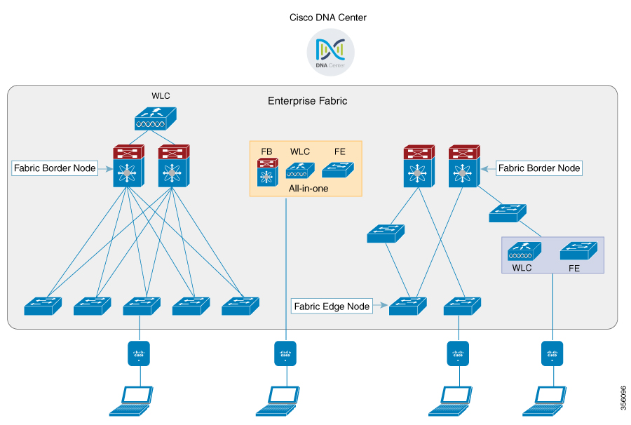
The figure covers the following deployment topologies:
-
All-in-one Fabric—When we have all Fabric Edge, Fabric Border, Control-Plane and controller functionality enabled on a Catalyst 4500E switch. This toplogy is depicted in the mid part of the figure.
-
Split topology—When we have Fabric Border, or Control Plane, or controller on a Catalyst 4500E switch with separate Fabric Edge. This toplogy is depicted in the left-most part of the figure.
-
Co-located Fabric Edge and Controller—When we have Fabric Edge and controller on a Catalyst 4500E switch. This toplogy is depicted in the right-most part of the figure.
Cisco DNA Center: Is an open, software-driven architecture built on a set of design principles with the objective of configuring and managing Catalyst 4500E Series switches.
Host ID Tracking Database(map-server and map-resolver in LISP): This database allows the network to determine the location of a device or user. When the EP ID of a host is learnt, other end points can query the database about the location of the host. The flexibility of tracking subnets helps in summarization across domains and improves the scalability of the database.
Fabric Border Node(Proxy Egress Tunnel Router [PxTR or PITR/PETR] in LISP): These nodes connect traditional Layer 3 networks or different fabric domains to the enterprise fabric domain. If there are multiple fabric domains, these nodes connect a fabric domain to one or more fabric domains, which could be of the same or different type. These nodes are responsible for translation of context from one fabric domain to another. When the encapsulation is the same across different fabric domains, the translation of fabric context is generally 1:1. The fabric control planes of two domains exchange reachability and policy information through this device.
Fabric Edge Nodes(Egress Tunnel Router [ETR] or Ingress Tunnel Router [ITR] in LISP): These nodes are responsible for admitting, encapsulating or decapsulating, and forwarding of traffic from the EPs. They lie at the perimeter of the fabric and are the first points of attachment of the policy. EPs could be directly or indirectly attached to a fabric edge node using an intermediate Layer 2 network that lies outside the fabric domain. Traditional Layer 2 networks, wireless access points, or end hosts are connected to fabric edge nodes.
Wireless Controller: The WLC provides AP image and configuration management, client session management and mobility. Additionally, it registers the mac address of wireless clients in the host tracking database at the time of client join, as well as updates the location at the time of client roam.
Access Points: AP applies all the wireless media specific features. For example, radio and SSID policies, webauth punt, peer-to-peer blocking, and so on. It establishes CAPWAP control and data tunnel to WLC. It converts 802.11 data traffic from wireless clients to 802.3 and sends it to the access switch with VXLAN encapsulation.
The SDA allows to simplify:
-
Addressing in wireless networks
-
Mobility in wireless networks
-
Guest access and move towards multi-tenancy
-
Leverage Sub-net extension (stretched subnet) in wireless network
-
Provide consistent wireless policies
AP Bring-up Process
The sequence of bringing up an AP is given below:
-
Switch powers up the AP (POE or UPOE)
-
AP gets an IP address from the DHCP server.
-
Switch registers the IP address of the AP with the map server.
-
AP discovers Cisco WLC through CAPWAP discovery.
-
After Datagram Transport Layer Security (DTLS) handshake, CAPWAP control tunnel is created between AP and Cisco WLC for control packets. CAPWAP data tunnel is created for IEEE 802.11 management frames. The AP image is downloaded and the configuration is pushed on AP from controller.
-
Cisco WLC queries the map server for the switch (RLOC IP) behind which the AP has been registered.
-
Cisco WLC registers a dummy MAC address with the map server.
-
Map server sends a dummy MAC address notification to the switch to create a VXLAN tunnel to AP.
-
AP is ready to accept clients.
Onboarding the Wireless Clients
The sequence of on boarding the clients are given below:
-
The wireless client associates itself to the AP.
-
Client starts IEEE 802.1x authentication on Cisco WLC (if configured) using CAPWAP data tunnel.
-
After Layer 2 authentication is complete, Cisco WLC registers MAC address of the client with map server.
-
Map server sends a notify message to switch with the client details.
-
Switch adds the client MAC to the Layer 2 forwarding table.
-
Cisco WLC moves the client to RUN state and the client can start sending traffic.
-
Switch registers the IP address of the client to the MAP server.
-
The switch decapsulates the VXLAN packet.
-
The switch forwards the DHCP packet to the DHCP server or relay.
-
The switch receives the DHCP ack for the wireless client. Switch learns the IP address of the client and sends an update to the map server.
-
Switch broadcasts the DHCP ack to all ports in the VLAN, including the AP facing VXLAN tunnels.
-
DHCP acknowledgement reaches AP, which forwards it to client.
-
AP sends IP address of the client to Cisco WLC.
-
Cisco WLC moves the client to RUN state.
Platform Support
|
Controller |
Support |
|---|---|
|
3504 |
Yes |
|
5520 |
Supported only on the local mode AP |
|
8540 |
Supported only on the local mode AP |
|
vWLC |
No |
|
AP |
Support |
|---|---|
|
802.11n |
No |
|
802.11ac Wave 1 |
Yes |
|
802.11ac Wave 2 |
Yes |
|
Mesh |
No |
|
Security |
Support |
|---|---|
|
Open and Static WEP |
No |
|
WPA-PSK |
Yes |
|
802.1x (WPA/WPA2) |
Yes |
|
MAC Filtering |
Yes |
|
CCKM Fast Roaming |
Yes |
|
Local EAP |
Yes. However, it is not recommended. |
|
AAA Override |
Supported for SGT, L2 VNID, ACL policy, and QoS policy. |
|
Internal WebAuth |
IPv4 clients |
|
External Webauth |
IPv4 clients |
|
Pre Auth ACL |
IPv4 clients |
|
FQDN ACL |
No |
|
IPv6 |
Support |
|---|---|
|
IPv6 Infra Support |
No |
|
IPv6 Client Support |
Yes (From Release 8.8 onwards) |
|
Features |
Support |
||
|---|---|---|---|
|
IPv4 ACL for Clients |
Yes. Flex ACL for ACL at AP. |
||
|
IPv6 ACL for Clients |
Yes (From Release 8.8 onwards) |
||
|
P2P Blocking |
Supported through security group tag (SGT) and security group ACL (SGACL) on the switch for clients on the same AP. |
||
|
IP Source Guard |
Switches |
||
|
AVC Visibility |
AP |
||
|
AVC QOS |
AP |
||
|
Downloadable Protocol Pack updates |
No |
||
|
Device profiling |
No |
||
|
mDNS Proxy |
No |
||
|
MS Lync Server QOS Integration |
No |
||
|
Netflow Exporter |
No |
||
|
QoS |
Yes (Metal profiles and rate limiting) |
||
|
Passive Client/Silent Host |
No |
||
|
Location tracking / Hyperlocation |
Yes |
||
|
Wireless Multicast |
Yes
|
||
|
URL Filtering |
No |
||
|
HA |
Controller to controller |
Migration From Converged Access
The following list shows the migration process from converged access to fabric wireless:
-
Bring up the WLC with image supporting fabric mode.
-
Configure the network with the fabric mode for the appropriate subnets, using an APIC-EM or CLIs. We recommed that you use APIC-EM for this purpose.
-
Configure the discovery mechanism such that the DHCP discovery on the new AP subnet should lead to the controller supporting fabric mode.
-
When the AP comes up, do a DHCP request and get the IP address in the AP VLAN.
-
The AP creates a control plane CAPWAP tunnel with the WLC.
-
Based on the configuration, the WLC programs the AP for the fabric mode.
-
AP follows the SDA for wireless flow.
 Note |
|
Restrictions
-
In a preauthentication scenario, IP addresses (either IPv4 or IPv6) learned via DNS resolution are lost after Cisco WLC switchover.
-
HA sync for Fabric related statistics is not supported.
Additional References
For more information about software-defined access wireless, see the SD-Access Wireless Design and Deployment Guide at https://www.cisco.com/c/dam/en/us/td/docs/cloud-systems-management/network-automation-and-management/dna-center/deploy-guide/cisco-dna-center-sd-access-wl-dg.pdf.
 Feedback