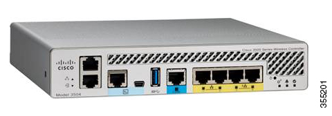
Overview of Cisco 3504 Wireless Controller

Cisco 3504 Wireless Controller provides centralized control, management, and troubleshooting for small- to medium-sized enterprises and branch offices. It offers flexibility by supporting the following deployment modes in the same controller:

  • Centralized mode for campus environments

  • Cisco FlexConnect mode for lean branches managed over WAN

  • Mesh (bridge) mode for deployments in which full Ethernet cabling is unavailable

As a component of the Cisco Wireless solution, Cisco 3504 Wireless Controller provides real-time communication between Cisco Aironet Access Points, Cisco Prime Infrastructure, and Cisco Mobility Services Engine. Cisco 3504 Wireless Controller is interoperable with Cisco 5520 and 8540 Wireless Controllers.

For more information about features and benefits, see the Cisco 3504 Wireless Controller datasheet.

Figure 1. Cisco 3504 Wireless Controller

Summary of Cisco 3504 Wireless Controller Features

Table 1. Cisco 3504 Wireless Controller Features

Feature

Description

Chassis Height

One rack-unit (1RU)

Throughput

4 Gbps

Note 

While the mGig port supports 5-Gbps PHY rate, data plane performance is limited to 4 Gbps

Number of APs supported

150

Number of clients supported

3000

Processor

Cavium Network Processor—CN7240-AAP 8-core, 1.5 GHz

Memory Options

  • Control/Data Plane Memory—8GB DDR4

  • Boot Flash—8MB SPI NOR Serial Boot

  • Bulk Flash—32GB eMMC

Redundancy, Service Ports

2x 1G Cu

Data Ports

1x 5G/mGig Cu, 4x 1G Cu (2 ports 802.3at PSE)

Storage Temperature

–4° F to 158° F (–20° C to 70° C)

Operating Temperature

32° F to 104° F (0° C to 40° C)

Storage Humidity

0% to 95% RH non-condensing

Operating Humidity

5% to 95% RH non-condensing

Power Adapter

54VDC/1.05A, 12VDC/3.75A

Platform Components

Cisco 3504 Wireless Controller Front Panel

Figure 2. Cisco 3504 Wireless Controller Front Panel View
Table 2. Cisco 3504 Wireless Controller Front Panel Components

1

Service Port LED

2

Redundancy Port LED

3

Service Port (SP) (RJ-45) for out-of-band management

4

Redundancy Port (RP) (RJ-45).

Note 

The redundancy ports can be connected back to back or via an L2 switch.

5

CPU console port, which is an RS-232 port that supports an RJ-45 connector. At boot-up, the controller configures the RS-232 port as a console port with default settings of 9600, N, 8, 1. The boot-loader supports baud rates of 1200, 2400, 4800, 9600, 19200, 38400, 57600, and 115200. A default baud-rate recovery mechanism is not available; however, the bootloader ensures that the stored baud rate setting matches one of the allowed values before setting the baud rate. If a nonstandard value is detected, the baud rate will default to 9600.

6

Mini-B USB console port that can be used to perform software updates in addition to the already available transfer modes, namely HTTP, TFTP, FTP, and SFTP.

Note 

If the Mini-B USB console port is used, the CPU console port that supports RJ-45 connector is ignored. That is, only one of the two ports are ever active.

If you connect to both Mini-B USB port and the CPU console port, then the CPU console port takes precedence.

7

Type A 3.0 USB port used to perform software updates in addition to already available transfer mode, namely HTTP, TFTP, FTP, and SFTP.

8

1x 5 G/mGig port. This mGig port supports speeds of 5G, 2.5G, and 1G.

Note 

In a High Availability environment, it is not possible to change the configured port speed.

9 and 10

GigE ports

Gigabit Ethernet ports 1 and 2 are RJ-45 connector form-factors. These ports are designed so that 1500 VAC rms isolation (per the 802.3 specification) is met between chassis ground and any 48V/Ethernet signal.

11 and 12

GigE PoE PSE ports

Gigabit Ethernet ports 3 and 4 are 802.3at PoE-capable PSE ports, using RJ-45 connector form-factors.

Note 

The ports can be used for infra-switch connection using multiple an AP-Manager or data interface.

13

Reset button

  • Pushing the Reset button for less than 10 seconds resets the controller.

  • Pushing the Reset button for more than 10 seconds restores the controller to factory default configuration.

14

System LED that determines if the system is powered up.

15

Alarm LED that determines a status or error occurred. The status or error is posted on the console screen.

16

High Availability LED


Note

  • Wait at least 20 seconds before reconnecting an access point to the controller. Otherwise, the controller may fail to detect the device.

  • We recommend that you configure an AP-Manager interface per port.

  • Precautions for the direct AP connection: Do not configure interfaces on the physical ports, if AP is connected to the port. If an interface is configured on the port where AP is connected, the behavior is undefined. If the physical ports are configured, remove it and reload the controller.

    Direct AP connection is not supported in a High Availability scenario.


Link Aggregation

In Cisco 3504 WLCs, the default speed configuration of the mGig port is 1000 Mb. To allow 2.5 Gb or 5 Gb operation, you have to change the maximum port speed configuration. To do this, on the WLC CLI, enter the config port maxspeed port-number command, or on the WLC GUI, navigate to Controller > Ports and then specify the maximum speed for the relevant port number.

Cisco 3504 WLC allows the use of the mGig port and the Gigabit ports in combination, and LAG is supported across all 5 ports. However, if the maximum speed of the mGig port is increased, the Cisco 3504 WLC will automatically decrease the maximum speed of the Gigabit ports per table below.

Table 3. Port-Speed Combination Specifications

mGig

Port 1

Port 2

Port 3

Port 4

1000

1000

1000

1000

1000

2500

1000

1000

100

100

5000

100

100

100

100

LAG is supported across all 5 ports. When LAG is enabled, the individual port speeds will follow the table above.

Front Panel LEDs: Definitions of States

Table 4. System LED Indicators

Color

Description

Off

System not receiving power.

Blinking Green

System boot

Blinking Amber

Boot-loader is active and waiting for user input from the system console

Table 5. Alarm LED Indicators

Color

Description

Blinking Green

Controller image upgrade

Amber

Controller status activity, such as firmware upgrade

Blinking Amber

Controller error. For example, a temperature error exists.

Table 6. High Availability LED Indicators

Color

Description

Solid Green

HA port paired with peer controller

Slow Green Blink

Pairing/HA Standby HOT

Slow Amber Blink

Bootup (Primary/Secondary) and HA Standby COLD

Fast Amber Blink

HA maintenance

Solid Amber

Peer not found

Off

Standby/HA disabled

Cisco 3504 Wireless Controller Rear Panel

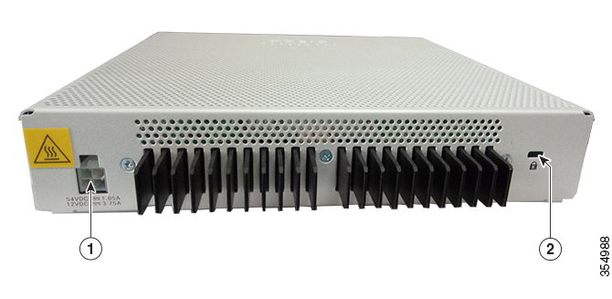
Figure 3. Cisco 3504 Wireless Controller Rear Panel View
Table 7. Cisco 3504 Wireless Controller Rear Panel Components

1

External 115W, dual output 54V/12VDC power adapter

2

Kensington security slot